
Abstract
This article presents an improved theoretical solution with the new prestressed – fibre-reinforced polymer (FRP) – model. The prestressing technique employed in this article was developed and refined by the prestressed force model coupled with the externally applied load and the fiber orientation effect. The new theoretical improved solution for the shear lag is developed. Comparisons are made with beams externally reinforced with a plate unstressed for different theory and the beams reinforced with a prestressed plate FRP. This research gives a numerical precision in comparison with the other studies that neglect the effect of prestressed plate model coupled with the thermal loads and fiber orientation impact. The physical and geometric properties of materials are taken into account and that may play an important role in reducing the interfacial stresses magnitude.
Keywords
Introduction
In recent years, there has been extensive research on the use of fibre-reinforced polymer (FRP) composites for the replacement of steel plates in plate bonding. The corrosion resistance and high strength-to-weight ratio, low maintenance cost and general versatility of FRP, make them attractive for plate-bonding applications. Indeed, there is considerable interest worldwide in the field of FRP for civil engineering and mechanical infrastructure, and much research has been carried out on a variety of important topics. 1 – 4 The widely used strengthening method of simply bonding FRP, such as carbon fibre, aramid, and glass fibre, for strengthening a structure generally produces a debonding failure prior to the attainment of the tensile strength of the FRP being used. 5 – 8 In recent applications, the use of prestressed laminates has been explored both in laboratory tests and in field applications on bridges and other types of structure. 9 – 11 By prestressing the laminate, the ultra-high tensile strength of the composite material can be better utilized, which gives a more effective strengthening scheme. Also in steel structures, compressive stresses introduced to the tension flange of a steel beam, for instance, will improve fatigue resistance of the steel beam. 12 – 18 Furthermore, the strengthening effect obtained when prestressed FRP laminates are employed will not only be limited to additional imposed loads on the strengthened structure but will also participate in carrying a portion of the dead load. Analysis of interfacial stresses in beams with bonded plates has been performed by several researchers. 1 –7,19– 21 Most of these investigations, however, did not simultaneously consider the effects of axial force, thermal effect, bending and shear deformations in the beam, and the fiber orientation bonded plate, which may lead to results without sufficient accuracy in some cases.
The problem of interfacial stresses when prestressed laminates are used in strengthening and repair was treated only by Al-Emrani and Kliger 22 and Benachour et al. 23 In the first investigation, only interfacial shear stress was studied and the analyzed beam was not loaded, and in the second investigation a rigorous solution for interfacial stresses in simply supported beams strengthened with bonded prestressed FRP plate is developed including the variation in FRP plate fiber orientation, however, did not consider the effects of bending and thermal deformation in the plate and shear deformations model in the beam. In this article, a new theoretical solution and a general model are developed to predict both shear and normal interfacial stress in simply supported beams strengthened with bonded prestressed FRP laminates, and an improved new shear lag and prestressed laminates model is developed.
Basic assumptions
The following basic assumptions were made in this study.
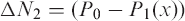
Figure 1(a) shows the geometric model for structure, Figure 1(b) shows an infinitesimal element of a beam with a reinforced FRP plate. Figure 1(c) shows a schematic sketch of the steps involved in strengthening a beam with a bonded prestressed laminate. P0 is the initial prestressing force in the laminate and Pl is the residual prestressing force in the laminate upon removing the prestressing device.
Structure configuration: (‘a’ Soffit-plated beam, ‘b’ Infinitesimal element of structure, ‘c’ Steel beam strengthened with bonded prestressed laminate).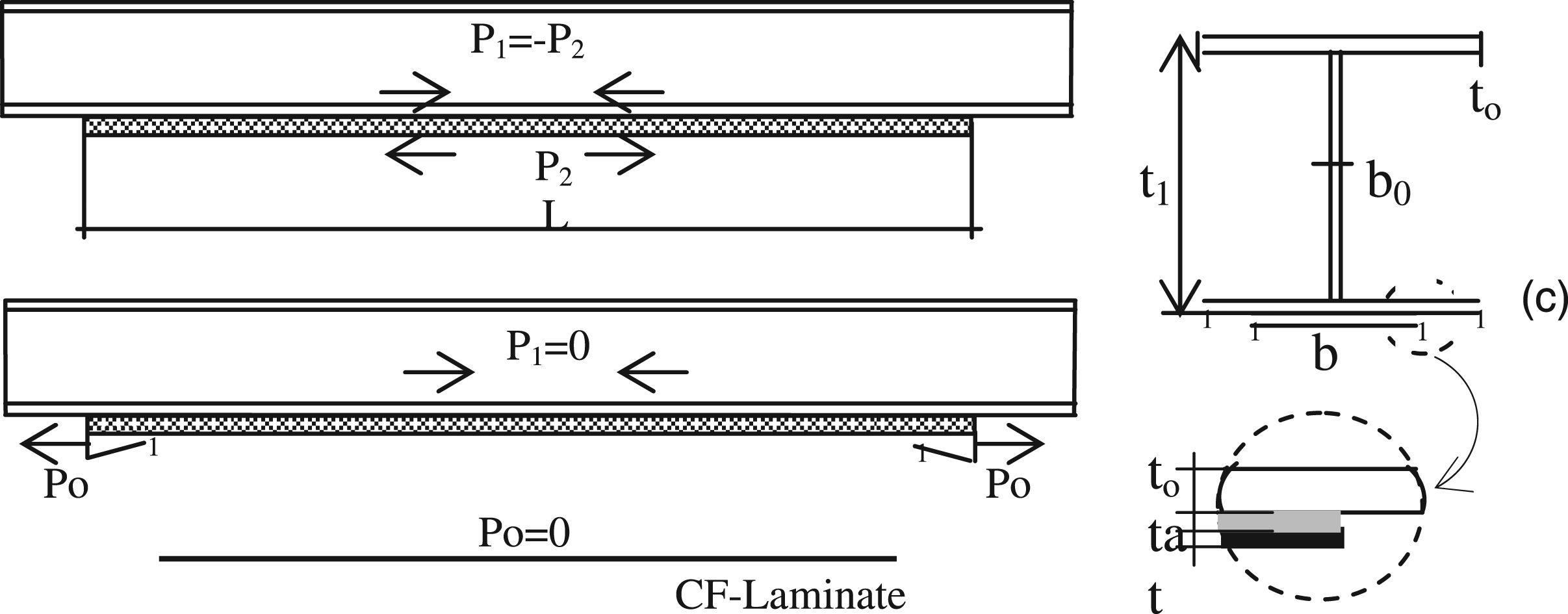
The following assumptions are used in this study:
All materials considered are linear elastic. The beam is simply supported and shallow, that is, plane sections remain plane in bending. No slip is allowed at the interface of the bond (i.e., there is a perfect bond at the adhesive steel or FRP plate interface). The shear stress analysis assumes that the curvatures in the beam and plate are equal (since this allows the shear stress and peel stress equations to be uncoupled). However, this assumption is not made in the normal stress solution, that is when the beam is loaded, vertical separation occurs between steel beam and FRP plate. We note that this assumption is used in several works.
1
–
7
A parabolic shear deformation distribution, through the depth of both the beam and the bonded plate, is assumed. Bending deformations of the beam and FRP composites are considered.
Theoretical analysis
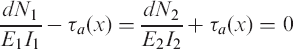
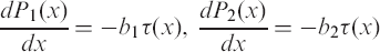
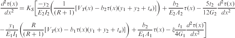
It was of utmost importance to evaluate the stresses in the adherents and adhesives before applying the prestressing force, in order to predict an optimal prestressing force. If a too large prestressing force was applied, a failure in the adhesive interface would occur after force release of the FRP laminates in the anchor block. For these configurations, the two differential equations for the horizontal equilibrium are given by:

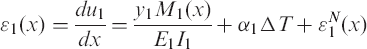
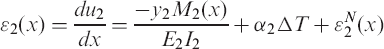
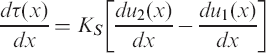
The compatibility equations for the adherents and the adhesive can be expressed as:
Where 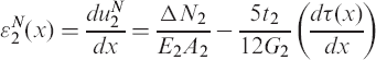
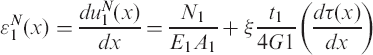

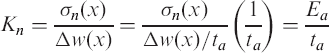
The strains at the base of adherend 2, considering all components of axial, bending, shear deformations, and thermal effect, and the composite laminate which is an orthotropic material and its material properties vary from layer to layer. In the current study, the laminate theory is used to determine the strain behaviors of the externally bonded composite plate in order to investigate the whole mechanical performance of the composite-strengthened structure.26,27

The expression of the total strain of the beam can be written as:

Distribution of shear stress
The shear stress at the layer of adhesive can be expressed as follows:
4
–
22


Note that the Young’s modulus along the axial coordinate of the joint or reinforcement is used in the case of composite materials. The first derivative of the shear stress of Equation (13) gives:
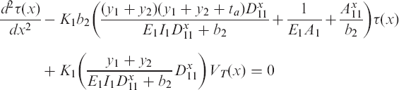
The differential equation governing the adhesive shear stress distribution is derived by differentiation of Equation (16),
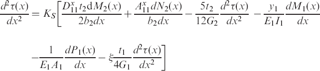


Substituting Equations (18) and (19) of the moment and the Equation (17) of axial forces into Equation (16) allows for the global differential equation of shear stress.
Equation (20) can be developed to give the general differential equation of shear stress.

The solution of the differential equation above is given by the Equation (23)

B1 and B2 are constant coefficients determined from the boundary conditions.

Distribution of normal stress
The normal stress is expressed by Equation (25).
1
–4,16–
22

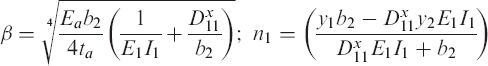
The differential equation of the normal stress is given as:

The general solution to this fourth-order differential equation is:

Numerical solution
Comparisons with existing models
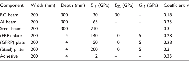
Geometric and material parameters.
Comparison of peak interfacial shear and normal stresses. a
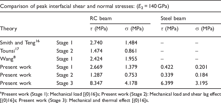
Present work (Stage 1): Mechanical load [(0)16]s; Present work (Stage 2): Mechanical load and shear lag effect [(0)16]s; Present work (Stage 3): Mechanical and thermal effect [(0)16]s.
The interfacial stress distributions obtained by the present study and other existing models are shown in Table 2. A good agreement of the interfacial stresses among all the comparisons is reached. The solutions of the peak interfacial stresses at the plate end derived by Smith and Teng 19 and Wang 8 are only for the mechanical load and are larger than from the one obtained by Tounsi. 20 It is anticipated that the peak shear and normal stresses predicted by the present analytical model are no larger than the ones8,19,20 for the mechanical load.
First configuration
Shear and normal stresses in the case of prestressing force (P0 = 0 and P0 # 0). The present new solution is compared, in this section, with the closed-form solution developed by Al-Emrani and Kliger,
22
which does not take into consideration external loads and it is limited to the evaluation of the adhesive shear stress. Figure 2(a)–(b) shows an almost exact agreement between the present results and those obtained by the method developed by Al-Emrani and Kliger.
22
Interfacial stresses distribution (different theory): Effect of prestressing force (‘a’ shear stresses, ‘b’ normal stresses).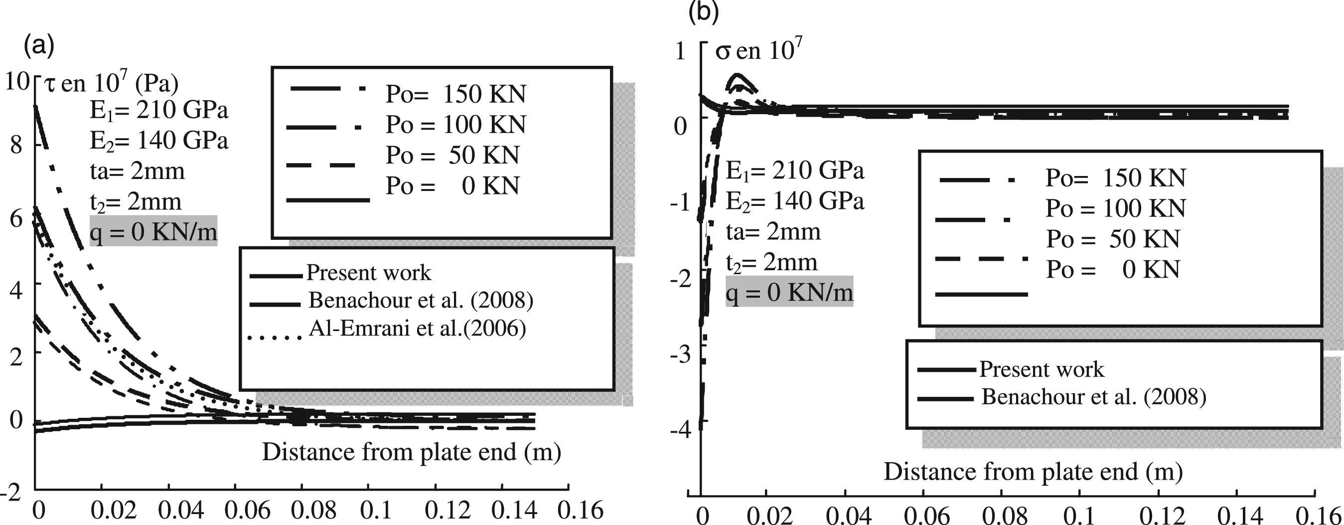
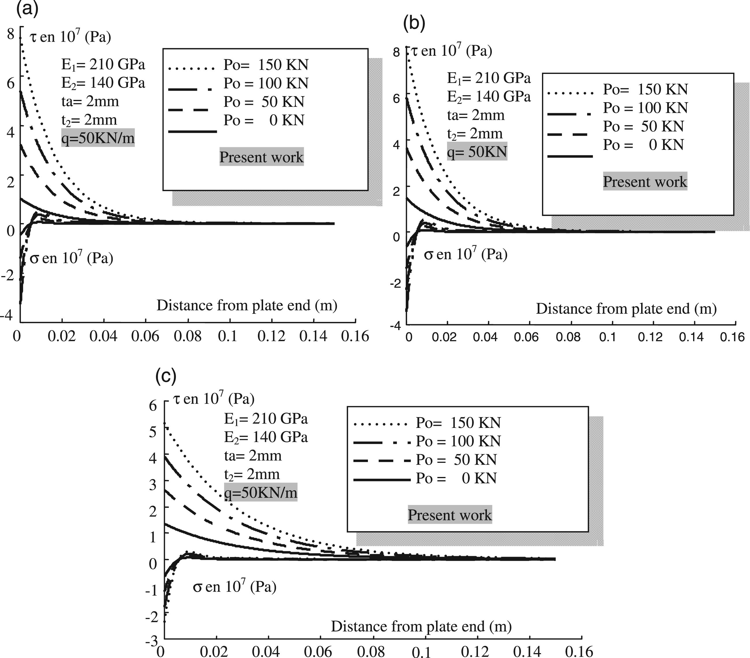
In this section, numerical results of the present solution are presented to study the effect of the prestressing force P0 on the distribution of interfacial stress in a steel beam strengthened with bonded prestressed FRP plate. Three values of P0 are considered in this study (P0 = 0, 50, and 100 kN). Figures 3(a)–(c) plots the interfacial shear and normal stress for the beam strengthened with bonded prestressed FRP plate.
The maximum value of interfacial stresses is localized to the ends of the composite plate, and this value becomes zero after a distance of about 60 mm from the plate edge. The presence of the prestressing force increases the value of the stress concentration at the edges of the plate. Interfacial stresses distribution: Effect of prestressing force (‘a’ mechanical load without shear lag effect [ΔT = 0], ‘b’ mechanical load without shear lag effect [ΔT = 50], ‘c’ mechanical load with shear lag effect [ΔT = 0]).
Second configuration
In this section, numerical results of the present solutions are presented with the effect of various parameters on the distributions of the interfacial stresses in beam bonded with an FRP plate, like adhesive layer thickness, plate thickness, adhesive stiffness, and FRP plate fibre orientation effect. These parameters influence the maximum values of the shear and the normal stresses in the bonding zone, as plotted in Figures 4–6.
Interfacial stresses distribution (‘a’ adhesive thickness effect, ‘b’ stiffness parameters) [(0)16]s). Stage 4. Interfacial stresses distribution (‘a,’ elasticity modulus impact, ‘b’ thickness effect) [(0)16]s, Stage 4. Interfacial stresses distribution (‘a’ thermal effect, ‘b’ fiber orientation impact), [(0)16]s. Stage 4.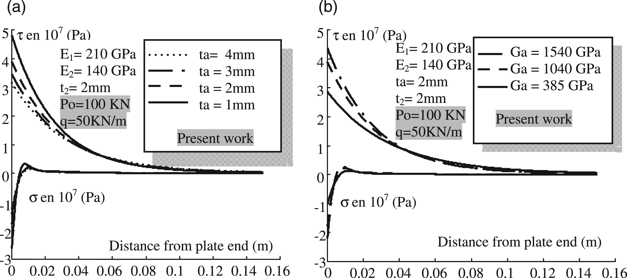
Effect of adhesive layer thickness and stiffness
Figure 4 shows the effects of the adhesive layer thickness and stiffness on the interfacial stresses. It is seen that increasing the adhesive layer thickness leads to significant reduction in the peak interfacial stresses and the adhesive stiffness to significant increase in the peak interfacial stresses. The maximum adhesive stresses are reached at the plate-end region and may be caused premature failure.
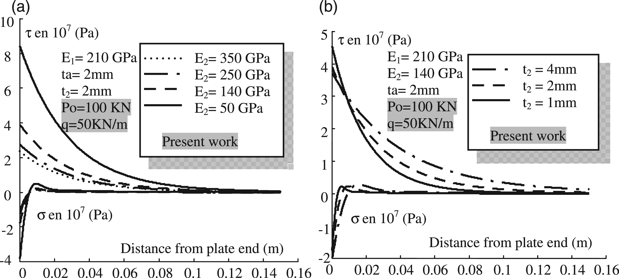
Effect of elasticity modulus and thickness of the strengthening plate
Figure 5(a) gives interfacial normal and shear stresses for the steel beam bonded with GFRP plate, FRP plate, steel plate, and CFRP plate, respectively, which demonstrate the effect of plate material properties on interfacial stresses. The results show that as the plate material became softer the interfacial stresses become greater. Figure 5(b) shows the effects of the plate thickness on the interfacial stresses. It is shown that the level and concentration of interfacial stresses are weakly influenced by the FRP plate thickness.
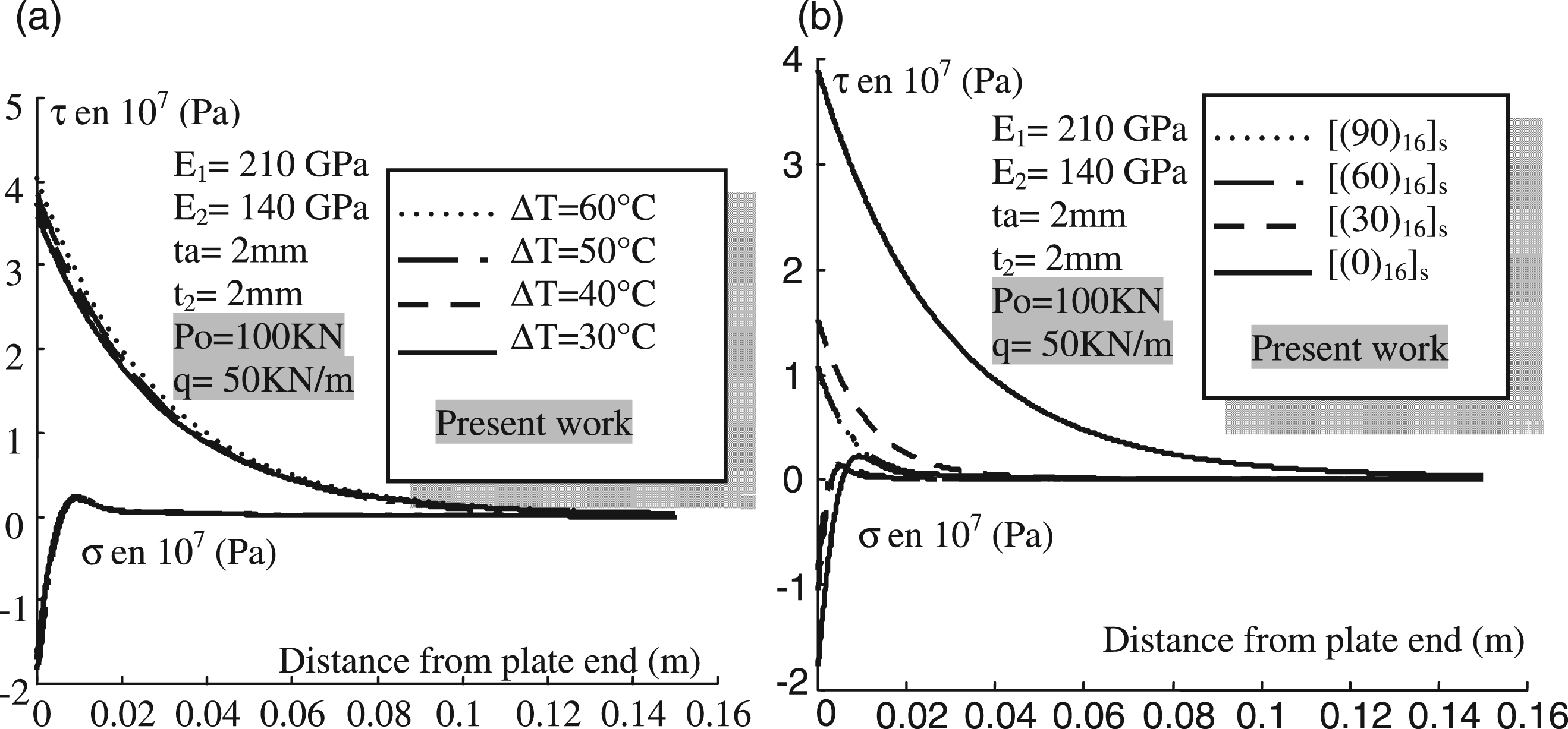
Effect of the temperature expansion of the structure
The influence of temperature of the strengthened beam region ΔT appears in Figure 6(a). The maximum adhesive stresses also increases with increasing temperature in the structure. Another important problem in beams reinforced with FRP plates is the large difference between the coefficients of thermal expansion. The coefficient of thermal expansion of the beam is of 10.2 × 10⁻⁶/°C, whereas the coefficient of thermal expansion of the plate is nearly zero, so, that substantial longitudinal shear stresses and normal tensile stresses can be developed in the adhesive layer near the ends of the FRP plate, as a result of the difference between the thermal coefficients for the 50°C temperature increase, the stresses in the adhesive at the end of the plate would be close to the failure stress.
Effect of the fibre orientations
The use of the FRP plate with different fibre orientations results changes the effective thickness effect of the composite plate. Having high-strength fibres aligned in the beam direction would maximize the thickness of the plate, while having the fibers aligned perpendicularly to the beam axis would greatly reduce the plate thickness. The maximum adhesive stresses increase with increasing alignment of all high-strength fibers in the composite plate in beam’s longitudinal direction x. The effects on adhesive stresses with different fibre orientation from the beam’s longitudinal direction are shown in Figure 6(b).
Conclusions
In this study, an improved prestressed composites model and the fiber orientation theory are proposed to model structures strengthened by an externally prestressed bonded plate. The ignored terms, such as the contribution of interfacial stresses of adherends deformations and the thermal effect coupled with the prestressed force and fiber orientation model, in the previous solutions, have been included in the present study, by introducing the improved solution. The improved solutions have been validated by comparing with the existing solutions. The effects of both the normal and shear deformations are presented and found to be an important factor influencing the interfacial stresses distribution in general. Compared with the previous studies, the present model provides more accurate prediction of the interfacial stresses distributions along the adhesively bonded interface. Furthermore, the improved solution is more general in nature, and it is applicable to more general load cases and for the adherends made of all kinds of materials. This work takes part as a new technique for strengthening and repairs the damaged structures. The results of this work allow engineers to design new materials that offer ultra-high tensile strength of the composite material, which gives a more effective strengthening scheme. It is obvious that a vast amount of scientific work is required to develop final strengthening solutions and implementation of the techniques in full-scale field structures.