
Abstract
Repair of cracked components by an adhesively bonded composite patch has gained acceptance in aerospace structures. The advantages of the double symmetric repair compared to the single one are well known. These advantages permit a significant reduction of the stress intensity near the repaired defect. In this study, a new approach was used to determine the advantage of the double symmetric patch: it is the determination of the mass gain obtained by the use of the double patch if the two techniques (single and double patches) give the same stress intensity at the crack tip. The mass gain was estimated numerically using the three-dimensional finite element method for repaired inclined cracks. The obtained results show that the mass gain eventually obtained by the use of the double patch can be very significant.
Keywords
INTRODUCTION
The use of externally bonded composite patches for repairing cracks and defects in aircraft structures gains a large success in the recent years, what accelerated the researches in this domain [1–6]. The bonded composite repair carries a part of the loads acting at the crack tip throughout the adhesive. This technique is promising because composite laminates are non-corroding, conformable, easy to fabricate and have high specific modulus and strength.
A repaired crack can be viewed as being bridged by a series of distributed springs sprang between the crack faces [7–12]. Under fatigue loading, these springs restrain the opening of the crack, and thus reducing the stress-intensity factor (SIF). To analyze the effect of this bridging mechanism on the residual plastic wake behind the crack tip, the crack bridging theory [13] is employed together with a crack-closure model [14] to analyze the steady-state closure of patched cracks subjected to constant amplitude loading. The analytical consideration proves that under small-scale yielding condition (the applied stress is far smaller than the material's yield stress), the steady-state crack-closure level depends only on the applied stress ratio and is almost identical to that corresponding to un-repaired cracks subjected to the same applied stress ratio. This finding has been verified by a finite element analysis. Furthermore, the transient crack-closure behavior following an overload, which is the main mechanism responsible for crack growth retardation, has also been investigated by the finite element method. The results reveal that patched cracks exhibit the same transient decrease/increase in the crack-closure stress as un-patched cracks. Based on these findings, a correspondence principle relating the transient crack-closure behavior of patched cracks to that of un-patched cracks is proposed. Several authors [15–20] showed that the SIF for patched crack exhibits an asymptotic behavior as the crack length increases. This is due to the stress transfer toward the composite patch throughout the adhesive layer.
Bachir Bouiadjra et al. [21] showed that the adhesive properties must be optimized in order to allow the transmission of the stresses toward the patch and to avoid the adhesive failure. Concerning the mechanical properties of the patch, it is known that only the boron/epoxy and the graphite/epoxy are used because of their excellent load transfer characteristics [1]. One can conclude that the improvement of the patch performances by the assessment of the properties of the composite and the adhesive prove to be more difficult and expensive. The unique parameter that remains is the patch thickness. Bachir Bouiadjra et al. [21] showed that for a single patch repair, the increase of the patch thickness about 50% reduces the SIFs at the same order and they affirmed that for a better distribution of the stresses, it is preferable to use a multiple layers of bonded composite patch. One of means that can strengthen these ideas is the use of the double-sided symmetric patch. Many authors have shown the advantage of the double-sided symmetric patches experimentally and numerically, among them are Ting et al. [4], Fekirini et al. [22], Bachir Bouiadjra et al. [23], and Belhouari et al. [24]. All these authors observe that the double-sided symmetric patch reduces the stress intensity more at the crack tip. In addition, it annuls the bending effect due to the eccentricity of the patch.
In this study, the comparison between the circular single and double composite repairs is made with new vision. Indeed, the mass gain eventually obtained by the use of the double symmetric patch is estimated numerically. This gain can give us an approximate evaluation of the repair cost reduction that can generate the use of the double symmetric patch.
FINITE ELEMENT MODEL
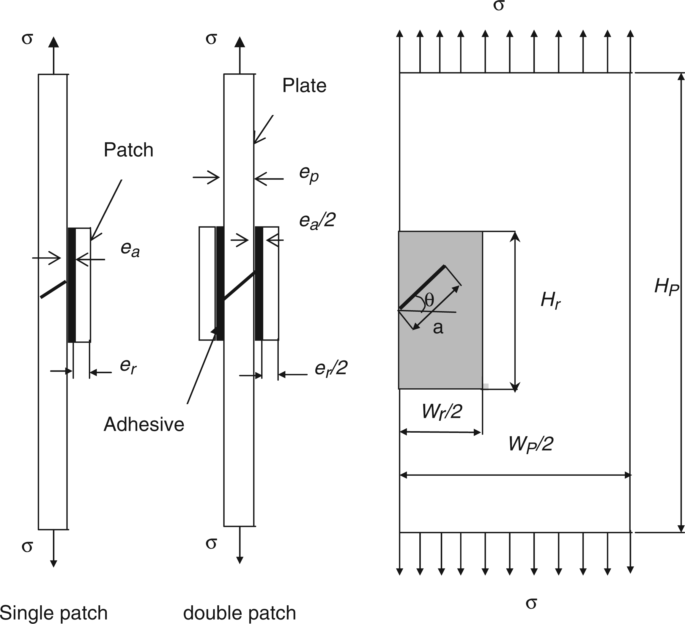
To study the geometry of repaired cracks in mixed mode, let us consider a thin elastic aluminum plate with the following dimensions (Figure 1): Hp = 254 mm, Wp = 127 mm and ep = 5 mm. An edge inclined crack with length a = 25 mm is supposed to exist in the plate as shown in the figure. The crack is repaired with boron/epoxy composite patch with the following dimensions: Wr = 65 mm, Hr = 75 mm and er = 2 mm. The patch thickness for double patch is half of that of single patch (Figure 1). The patch is bonded to the plate with FM 73 adhesive with thickness ea = 0.15 mm. The plate is subjected to a remote uniaxial tensile in the y direction σ = 70 MPa. The material properties of the plate, patch and adhesive are:
Young's modulus Ep = 72 GPa, Poisson's ratio νp = 0.33. longitudinal Young's modulus Er1 = 210 GPa, transversal Young's modulus Er2 = 19.6 GPa, shear modulus Gr = 5460 GPa, longitudinal Poisson's ratio νr1 = 0.3, transversal Poisson's ratio νr2 = 0.2. shear modulus Ga = 0.42 GPa. Geometrical model.
Plate (aluminium alloy 2024 T3):
Patch (boron-epoxy):
Adhesive (FM 73):
The finite element model of Figure 1 configuration was performed using the code Franc2D/L [25] developed at the University of Kansas. A layered structure is actually a three-dimensional structure. A three-dimensional finite element or mathematical modeling of such a structure will involve several degrees of complexity. In this study, simplifying assumptions are made which still allow us to capture the essential features of the response. These assumptions include:
Each layer is considered as an individual two-dimensional structure under a state of plane-stress. Individual layers can be connected with adhesive bonds. It is assumed that the adhesive layer is homogeneous, linear elastic, and isotropic. The adhesive is assumed to deform only in shear and the shear strain is uniform throughout the adhesive thickness. The surface shear transmitted through the adhesive is assumed to act as surface traction on the adherends.
The global structure (plate and patch) is meshed using standard quadrilateral elements and eight nodes. This type of evidence is effective in analyzing linear elastic and has the advantage of fully characterize the singularities in crack heads. The mesh has been refined as the obtained results converge with an optimum CPU time. The maximal number of elements used is 32,525 for the global structure without crack. Figure 2 shows a typical mesh model for the plate, the patch, and near the crack tip.
Typical model of the quarter of the structures and near the crack tip.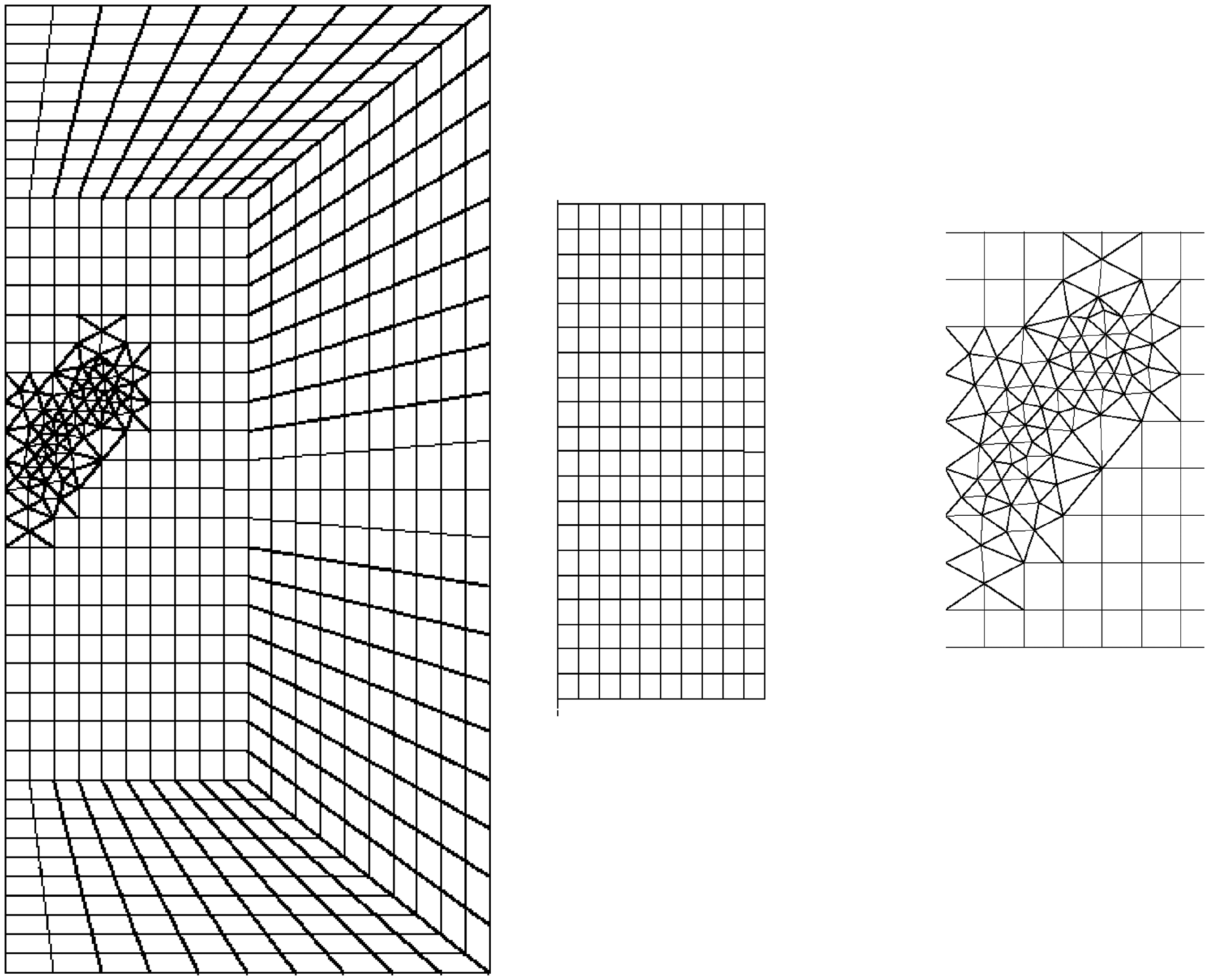
It is important to remember that the common portion to the plate and the patch must have the same mesh. The leading singularity of crack can be integrated into the solution by replacing the elements ahead of crack special elements quart point. The SIF that governs the process of fracture is calculated using the method of displacement field ahead of crack.
RESULTS AND DISCUSSION
SIF Calculation for Single and Double Composite Patches
Figures 3 and 4 present, respectively, the variations of the SIFs in modes I and II according to the crack inclination θ (er = 5 mm and a = 25 mm). It is shown according to Figure 3 that the reduction of mode I SIF (KI) between the single and double patches is maximal for θ = 0°. This reduction decreases with the angle θ. The difference of the SIF between the two techniques is about 36% for θ = 0° and this difference tends toward 0 for θ = 90°. This behavior is due to the fact that for θ = 0°, there is pure mode I and consequently the stress absorption by the patch is maximal which increases the performances of the double patch.
SIF vs the crack inclination θ of mode I for a = 25 mm. SIF vs the crack inclination θ of mode II for a = 25 mm.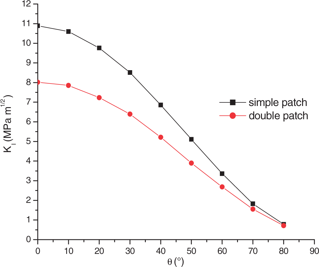
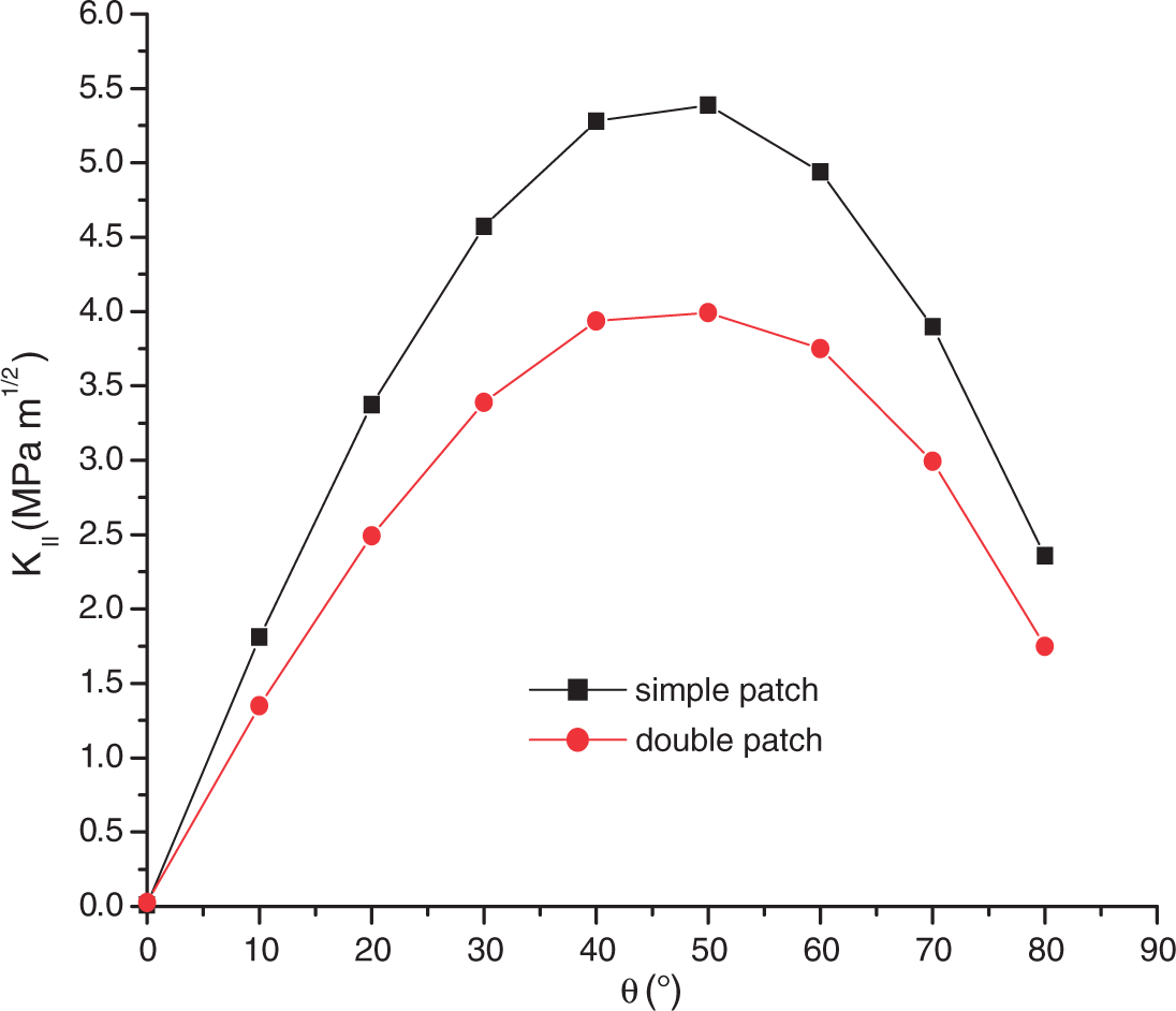
Concerning the mode II SIF (Figure 4). The reduction rate of KII obtained by the use of double patch technique is maximal for θ = 45°. The maximum rate is about 30%. This is due to the fact that the sliding mode of crack propagation (mode II) is maximal for θ = 45° and consequently the stress transfer between the patch and the plate is very significant, which explains the maximal reduction of KII by the double patch. In conclusion, the double patch reduces the SIF at the crack tip in both modes I and II.
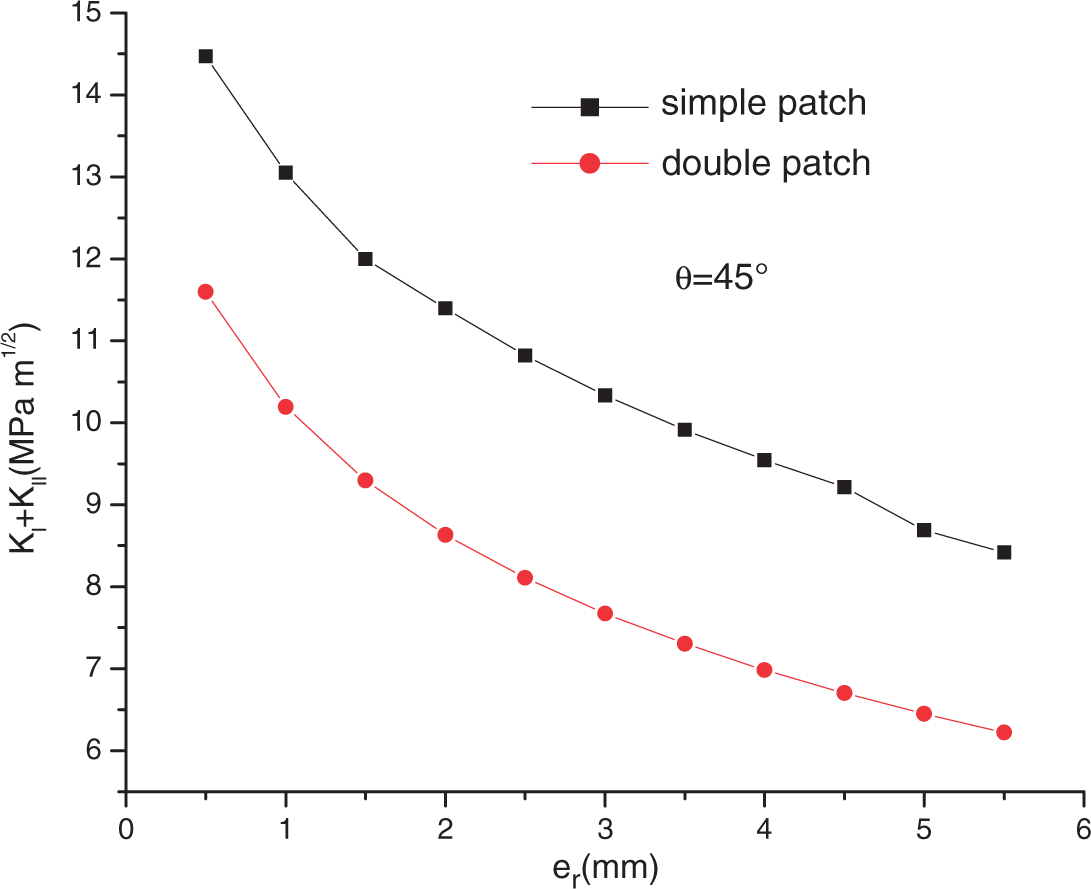
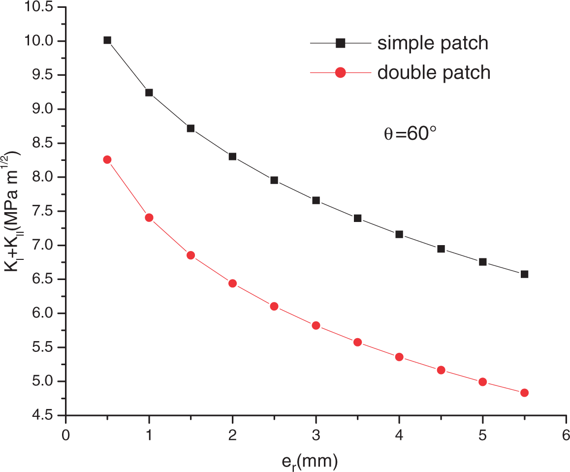
Before estimating numerically the mass gain obtained by using the double patch technique, it is useful to analyze first the variation of the sum of the two SIFs (KI + KII) according to the patch thickness for the two techniques (single and double patches). Figures 5, 6, and 7 present, respectively, the sum KI + KII according to the patch thickness for three crack inclinations: θ = 30°, 45°, and 60°. It can be seen, according to these three figures, that the reduction of the sum of the two SIFs is about 20% for weak values of the patch thickness and this reduction increases as the patch thickness increases too. It can also be noted that the angle θ = 60° presents the maximal reduction of KI + KII compared to θ = 45° and θ = 30°.
KI and KII vs the patch thickness for θ = 30°. KI and KII vs the patch thickness for θ = 45°. KI and KII vs the patch thickness for θ = 60°.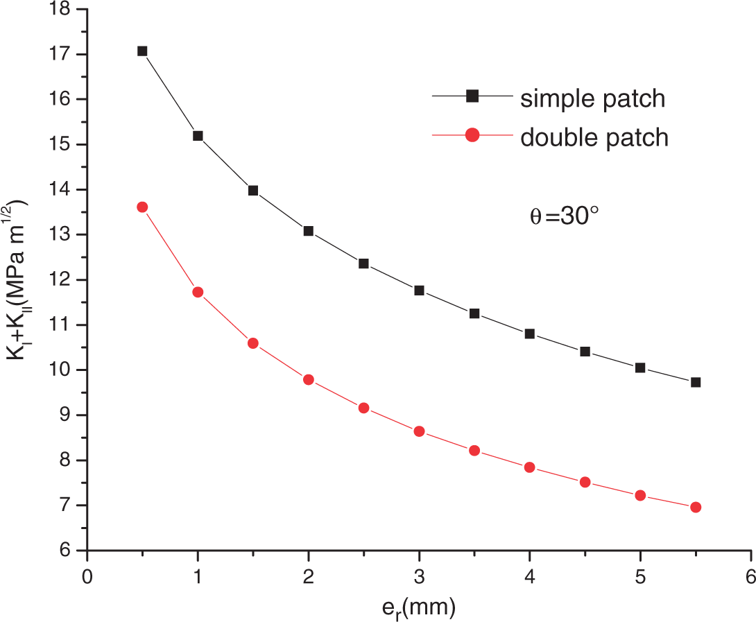
Mass Gain Estimation
The mass gain is defined for the case of mixed mode as the ratio between the thicknesses of the double patch and the single one giving the same sum KI + KII.
The mass gain of the double patch is defined by:
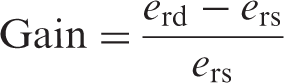
In order to calculate this gain, the sum of the SIFs (KI + KII) is plotted according to the patch thickness for the two configurations, and then the thickness giving the same sum KI + KII is determined graphically. The mass gain is finally calculated using the preceding equation.
Figure 8 presents the variation of mass gain according the crack inclination (θ) for a = 25 mm.
Mass gain vs crack inclination for a = 25 mm.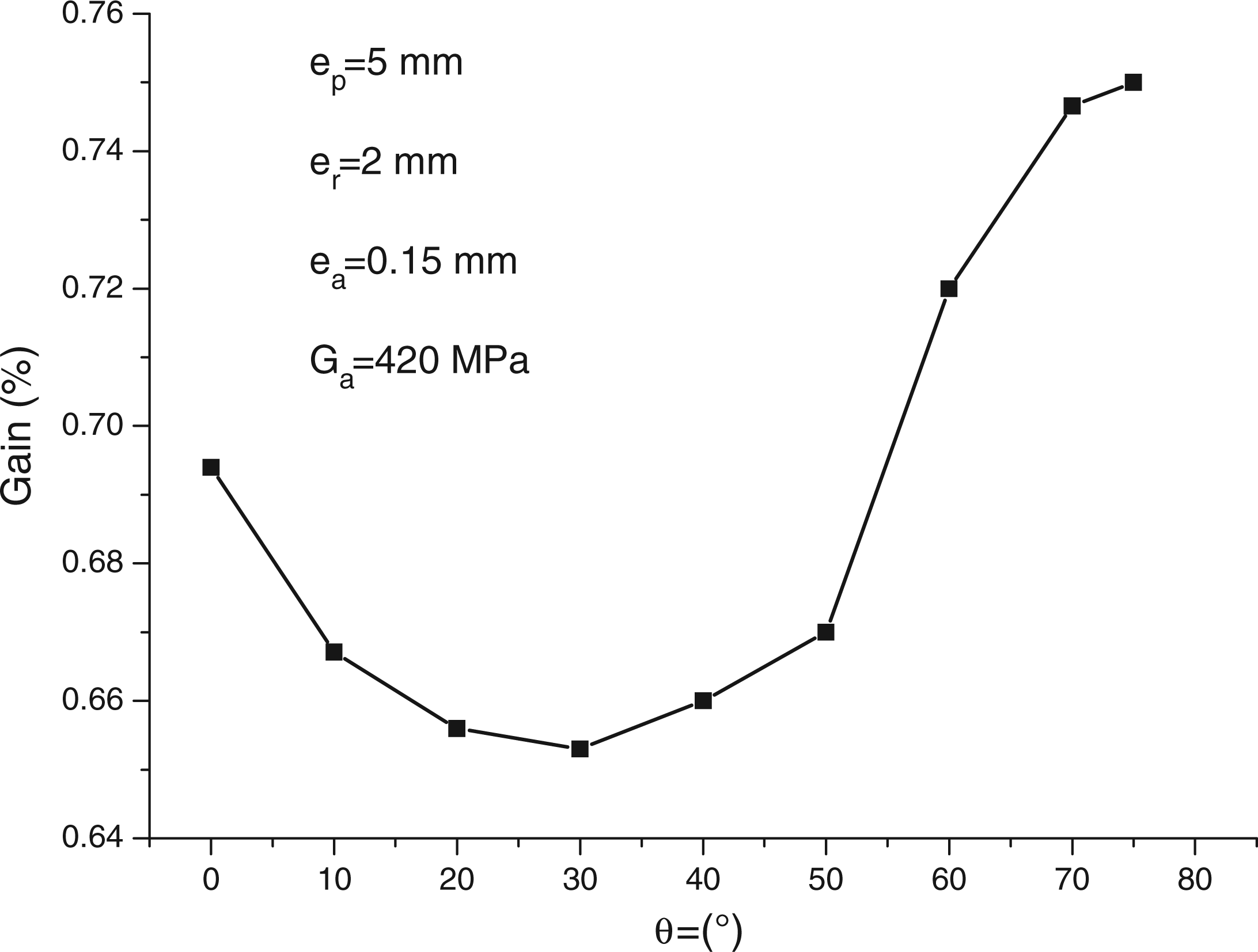
According to this figure, it can be noted that the mass gain decreases when the crack inclination varies between 0° and 30°. Beyond this last angle, the gain increases when the crack inclination increases too. It is clear that this gain becomes negligible when the angle approaches 90°. One can deduce that the performances of the double patches are minimal when the crack inclination is about 30°. This is due to the fact that for this angle, the normal and shear stresses absorption by the patch is weak, which explain the weak value of the mass gain. The combination of the two modes of crack propagation (Mode I + Mode II) leads to a higher value of the gain. This behavior is visible for an inclination of 60°.
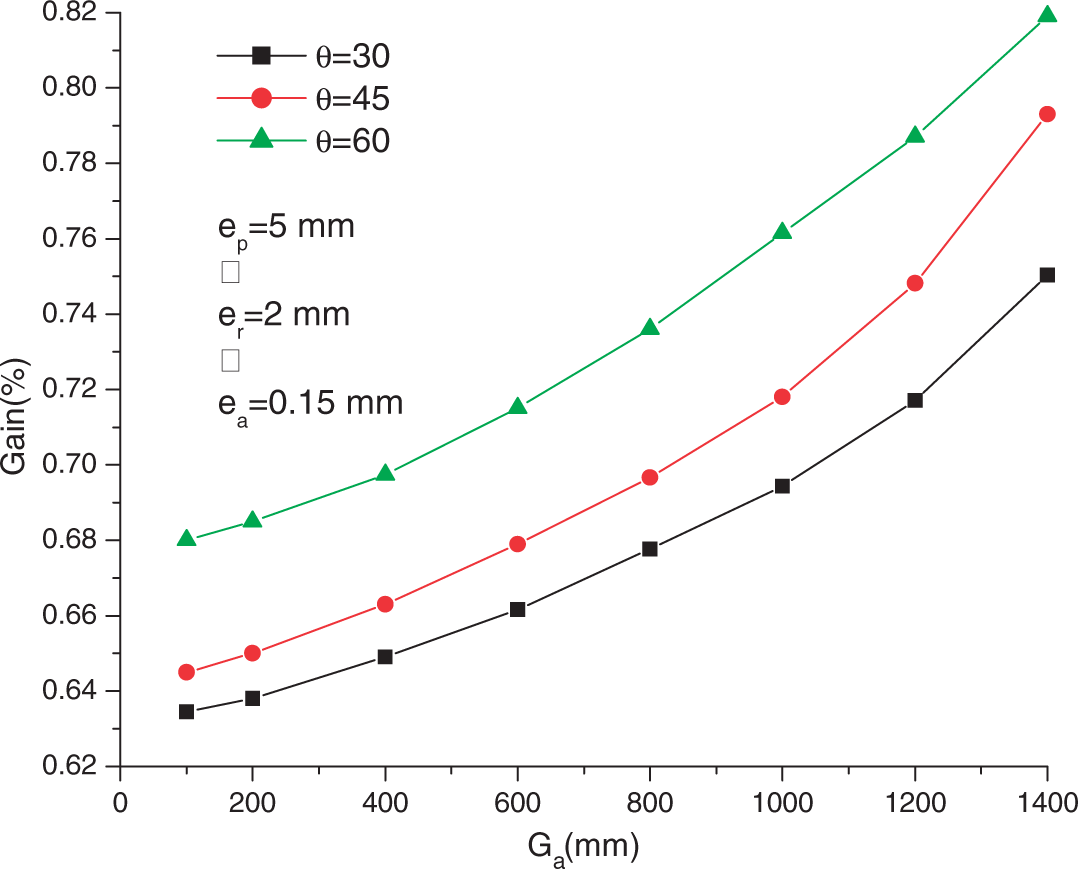
Effect of the Adhesive Shear Modulus on the Mass Gain Variation
The nature of the adhesive is considered one of the factors that may influence the effectiveness of the patch. The adhesive shear modulus (Ga) is the mechanical property which influences directly the distribution of the shear stresses in the adhesive layer. The shear stresses in the adhesive are related to its shear modulus by the relation:
Mass gain vs adhesive shear modulus for a = 25 mm.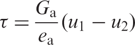
CONCLUSION
The finite element analysis showed that a significant mass gain that can be obtained by the use of double symmetric patch for repairing inclined cracked in aircraft structures can. This mass gain can reach the percentage of 60%. The maximal value of the mass gain is obtained when the crack inclination is about 60° and the minimum value is recorded foe crack inclination of 30°. The choice of an optimized value of the adhesive shear modulus can improve the advantage of the double symmetric patch. The optimized value of the adhesive shear modulus must equilibrate between the reduction of the SIF at the crack tip and the risk of the adhesive failure due to the increase of the shear stresses in the adhesive layer.