
Abstract
Surface patterning (micro-moulding) of dense, biomimetic collagen is a simple tool to produce complex tissues using layer-by-layer assembly. The aim here was to channelise three-dimensional constructs for improved perfusion. Firstly, collagen fibril accumulation was measured by comparative image analysis to understand the mechanisms of structure formation in plastically compressed collagen during µ-moulding. This showed that shape (circular or rectangular) and dimensions of the template affected collagen distribution around moulded grooves and consequently their stability. In the second part, this was used for effective fabrication of multi-layered plastically compressed collagen constructs with internal channels by roofing the grooves with a second layer. Using rectangular templates of 25/50/100 µm widths and 75 µm depth, grooves were µ-moulded into the fluid-leaving surface of collagen layers with predictable width/depth fidelities. These grooves were then roofed by addition of a second plastically compressed collagen layer on top to produce µ-channels. Resulting µ-channels retained their dimensions and were stable over time in culture with fibroblasts and could be cell seeded with a lining layer by simple transfer of epithelial cells. The results of this study provide a valuable platform for rapid fabrication of complex collagen-based tissues in particular for provision of perfusing microchannels through the bulk material for improved core nutrient supply.
Keywords
Introduction
Tissue development and maintenance is achieved through networks of interconnected biochemical and mechanical signals based on fundamental cell–cell and cell–matrix interactions.1–3 These interactions seem to govern most cell functions such as alignment, migration, proliferation and differentiation. The extracellular matrix (ECM) therefore plays an important role in regulating cell behaviour, through substrate stiffness/cell mechanics, spatial cues/topography and by supporting gradients of soluble factors, nutrients and dissolved gases. These phenomena are dependent on mass transfer/perfusion across the matrix and can be exploited in our aim to engineer living tissues and tissue models. Consequently, the importance of techniques to fabricate predictable, internal µ-structures for regulation of cell movement and mass transfer (i.e. channels and micro-vascular-like capillaries) is becoming more widely appreciated. In short, insertion of such internal channelling will be key to regulating gradients of nutrients, gases, wastes and regulatory proteins across engineered tissues – in biological terms, perfusion.
Collagen, the most abundant protein in the body, is a main component in the ECM and as such, is important in both making tissue-like constructs and in controlling their structure. Collagen-cell gels are good starting points for tissue fabrication and rapid fabrication methods using compression to generate tissue-like structure and density is well established.4,5 This rapid layer fabrication process uses cell-independent, collagen plastic compression (PC), which can be simply adapted to produce three-dimensional (3D), micro-moulded architectures. This involves using shaped templates to compress the collagen hydrogels and leaves a corresponding stable surface pattern in the fluid-leaving surface (FLS). 6
In the most common configuration, fluid flows out of the initial hydrogel, up into an absorbent plunger which simultaneously compresses. When an impervious object (i.e. a patterned template) is placed on the FLS the normally uniform fluid outflow dynamics are locally interrupted by the resulting deflection of flow. Rapid fluid outflow through the FLS deposits and compacts (and aligns) the less mobile collagen fibrils producing predictable shapes and fibril patterning in the FLS. 7
The resulting ability to generate predictable µ-topography at the same time as the tissue is being made can have considerable practical use. This includes the guidance of cells at surfaces and potentially recapitulation of stem cell behaviours by generating mimics of native 3D spatial niches, for example in the corneal limbus.8,9 Although these have so far concentrated on surface topography and so (outer) surface-cell control, the ability for PC to be repeated to produce serial multilayers raises the possibility that µ-structures could be generated which eventually lie on the core bulk of such layered constructs.
The aim of this study was to understand the controlling mechanisms of shape formation during micro-moulding at the collagen FLS, to allow it to be an integrated process in PC and rapid tissue fabrication. In particular, we aimed to test the idea that layering of fresh collagen over the top of grooves moulded into a previous layer would generate internal channels. In other words, that ‘roofing the grooves’ would fabricate capillary tubes, which run deep through (and perfuse) the bulk collagen material.
Materials and Methods
Preparation of collagen gels
Collagen gels were prepared as described previously. 4 Briefly, collagen gels were made up of a mixture of 80% acid soluble rat tail collagen type I (First Link, UK), 10% 10X concentration Modified Eagle's Medium (Gibco, UK) and 10% Dulbecco's Modified Eagle's Medium (DMEM) (Sigma, UK) supplemented with 10% (v/v) foetal calf serum (First Link, UK) and penicillin/streptomycin (500 unit ml−1 and 500 µg ml−1) (ICN Biochemicals, UK), which was neutralised drop-wise with 5 M NaOH. Neutralised collagen solution was kept on ice for 30 min to de-bubble. Cellular gels were prepared by adding HDF (2.5 × 10⁵ cells/well) suspended in complete DMEM to the neutralised collagen solution.
PC of collagen
Modified PC protocol was used in this study.
10
Briefly, neutralised collagen solution was aliquoted into wells of a 12-well plate (Orange Scientific, Belgium) and allowed to set for 30 min at 37℃. The fluid-removing elements consisted of a spirally wound roll of Whatman chromatography paper (120 cm in length, 4 cm in height (as supplied by the manufacturer, diameter = 22 mm)) and two discs of Whatman filter paper (Whatman UK), cut to the size of the well, which were placed on top of each collagen gel. In order to provide compressive load together with capillary action to drive fluid flow from the collagen gel, each gel was subjected to 29 g initial load, resting on the paper rolls (Figure 1(a)). Once compression was completed, liquid-containing paper rolls were removed, leaving the constructs in their respective wells.
Schematic illustration of plastic compression process. Collagen gels were set in the wells of 12 well-plate. (a) Absorbing elements, consisting of two discs of Whatman paper and a paper roll were placed on top of each gel followed by a weight. Micro-moulding was carried out by placing the template on top of the collagen gels prior to compression. Schematic illustration of the templates used for micro-moulding of the collagen showing cross-sections and dimensions of the templates for generating rectangular and (b), (c) circular cross-section channels.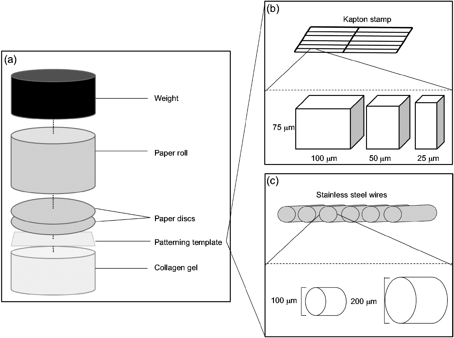
To create a horizontal density gradient within a collagen construct, collagen gels were prepared by casting 2, 3 or 4 ml of collagen mixture into the wells. The plate was then placed at an angle of 25° and allowed to set at 37℃ to give gels cast with an angle of 25°. 11 To compress these gels, only absorbing elements were used without the addition of a weight which could reduce or even completely remove the pre-set angle. The 2/3/4 ml gels were allowed to compress for 10/20/30 min, respectively.
Micro-moulding – introducing surface patterns
To introduce topography to the surface of collagen constructs, a pattern template was placed on top of 4 ml collagen gels (where the FLS forms) prior to compression and removed after (demonstrated in Figure 1). Two different template patterns were used for micro-moulding (Figure 1(b) and (c)): (1) Rectangular ridges of 75 µm thickness and 25, 50 or 100 µm widths arranged in a ladder-pattern made of Kapton (provided by TAP Biosystems, UK). (2) Circular template using stainless steel wires of 100 or 200 µm diameter (wires.co.uk) arranged in parallel and evenly spaced. To create roofed channels (microchannels), fresh neutralised collagen solution was set on top of the first, patterned layer and the compression process was repeated. Microchannels were fabricated in both acellular and cellular constructs.
Histology
PC acellular collagen constructs were fixed immediately with formalin for routine wax embedding and sectioning in the transverse plane at 10 µm thickness. Four consecutive sections of each construct were stained with Sirius Red. 12 Sections were imaged along their entire length using a light microscope (Olympus BH-2) and images were taken using an Olympus Camedia 2020Z (for densitometric analyses) or an AxioCam, Zeiss (for groove/channel analyses).
Image analysis of constructs with density gradients
Images were converted to grey scale and inverted for analysis using ImageJ (version 1.45), outlining each image sequentially across the entire construct section. The intensities of the pixels within each selection was measured and plotted as a ‘plot profile’ graph, using the ‘region of interest (ROI) Manager’ and the function ‘Multi-plot’, generating a graph for each image. Values from the analyses were pooled in sequence to generate a single graph representing the pixel intensities from one end of the construct to the other. For each construct, a mean was taken from three sections. The rate of change of pixel intensity with distance along the construct of these 3 and 4 ml ungraded samples was 2.2 ± 1.73 and 2.6 ± 1.64 × 10⁻⁴ µm−1, respectively. Three millilitre and 4 ml constructs fabricated at a 25° angle had measured collagen density gradients of 9.9 ± 6.2 and 5.9 ± 2.3 × 10⁻⁴ µm−1, respectively. These were significantly different to gels containing the same volume of collagen, but with no gradient, at p < 0.05.
Image analysis of micro-moulded constructs
Collagen distribution in the micro-moulded constructs was assessed by converting images to grey scale and inverted to give images with collagen in white against a black background. Using straight line measurements (line width: 20, line length: at least half the thickness of the construct), vertical parallel lines were drawn spanning from at least 50 µm on one side of a groove to at least 50 µm from the groove of the other side. These straight lines each represented an individual ROI. The mean pixel intensities of each ROI were measured using the multi-measure function in ImageJ and plotted against corresponding ROI position along the construct (Figure 3).
Average width and depth of the grooves was measured from the histological images with at least 10 measurements taken from each using AxioVision image program. Microchannels in the acellular PC constructs were assessed from the histological images. Microchannels in the cellular constructs were assessed qualitatively immediately after assembly and after 2 weeks in culture based on the distortion of the channel borders and occlusion of the channel opening with time in culture using scanning electron microscopy.
Scanning electron microscopy
Samples for scanning electron microscopy were fixed in 2% glutaraldehyde in 0.1 M sodium cacodylate buffer (pH 7.4) at 4℃ overnight, dehydrated and left to dry overnight. Dry samples were mounted on aluminium stubs, sputter-coated with gold palladium and viewed on a Joel scanning electron microscope (JSM 5500 LV, Japan) at 20 kV.
Development of cell-delivery technique
To evaluate the possibility of direct cell delivery into the grooves during the construct assembly, the following technique was tested. Cell suspension (HaCat cells, 1 × 10⁶ cells ml−1) was pipetted onto the autoclaved 100 µm Kapton templates, placed on to the bottom of the 12 well-plate and incubated at 37℃ for 2 h to allow cells to settle. A total of 2 ml of cell suspension was used to give total coverage of the well.
Collagen gels were then set in the 12 well-format as before in another plate. Prior to compression, templates were placed onto the gels cell-side down. Gels were then compressed as usual. After compression, templates were left on the gels for 2 h prior to removal to allow for cell transfer. A second layer of collagen was then added to trap cells in the microchannels. Constructs were cultured for 1 week and processed for histological evaluation as before.
Statistics
T-test was used where there was a maximum of two groups of variables, and one-way analysis of variance was used for two or more groups of variables. Error bars shown represent the standard deviation from the mean, and statistical significance was taken at p < 0.05.
Results
Previous work has indicated the key importance of the FLS in determining how the PC process progresses. 4 In particular, the FLS dictates how collagen fibrils accumulate and whether surface patterning (topography), produced by embossing or micro-moulding, is retained at its initial depth. In other words, reasonable fidelity between the embossed pattern and the embossing template can only be achieved when the template is pressed into the FLS. 6 This implies that a stiff, collagen-rich accumulation of matrix, at the template–gel interface, is essential for shape stability. In the first part of this study a simple denistometric, histochemical method was used to measure localised collagen accumulation after micro-moulding to establish where and how collagen fibrils accumulate at the FLS. The semi-quantitative map of high density collagen deposits was used to design a layer-engineering approach to fabrication of stable perfusion channels.
Mapping the FLS local collagen density
Figure 2(a) shows a typical analysis of collagen within a highly compacted FLS. The micrograph shows a thin PC collagen layer (around 50 µm), indicating the dense FLS at the gel top. Note the use of thin initial gels (<5.3 mm deep) was essential for this degree of asymmetry. Thicker (or ‘deeper’) pre-compression gels formed a secondary FLS on this opposite, basal surface, due to reversal of the fluid outflow part way through compression. The transverse x-line in Figure 2(a) and (b) indicates the scanning track used during image analysis to produce the density trace in (iii) and 3D map in (ii). In this case, (no embossing template) the extent and micro-localisation of dense FLS collagen accumulation is clearly evident (incidentally, indicating why fluid outflow falls off by this stage of compression). For comparison a similar scan is shown for a construct embossed using a circular cross-section, wire template (100 µm diameter, Figure 2(b)).
(a) Image analysis of an unpatterned PC scaffold, showing the stained section with -x-scanning-track line (i), with 3D and linear density scan plots (ii), (iii). (b) Similar stained section (i), 3D (ii) and linear (iii) plots through the collagen below a 100 µm embossed groove. (Inset) SEM micrograph showing the surface appearance of a micro-moulded (arrowed) groove produced with a 200 μm diameter stainless steel wire.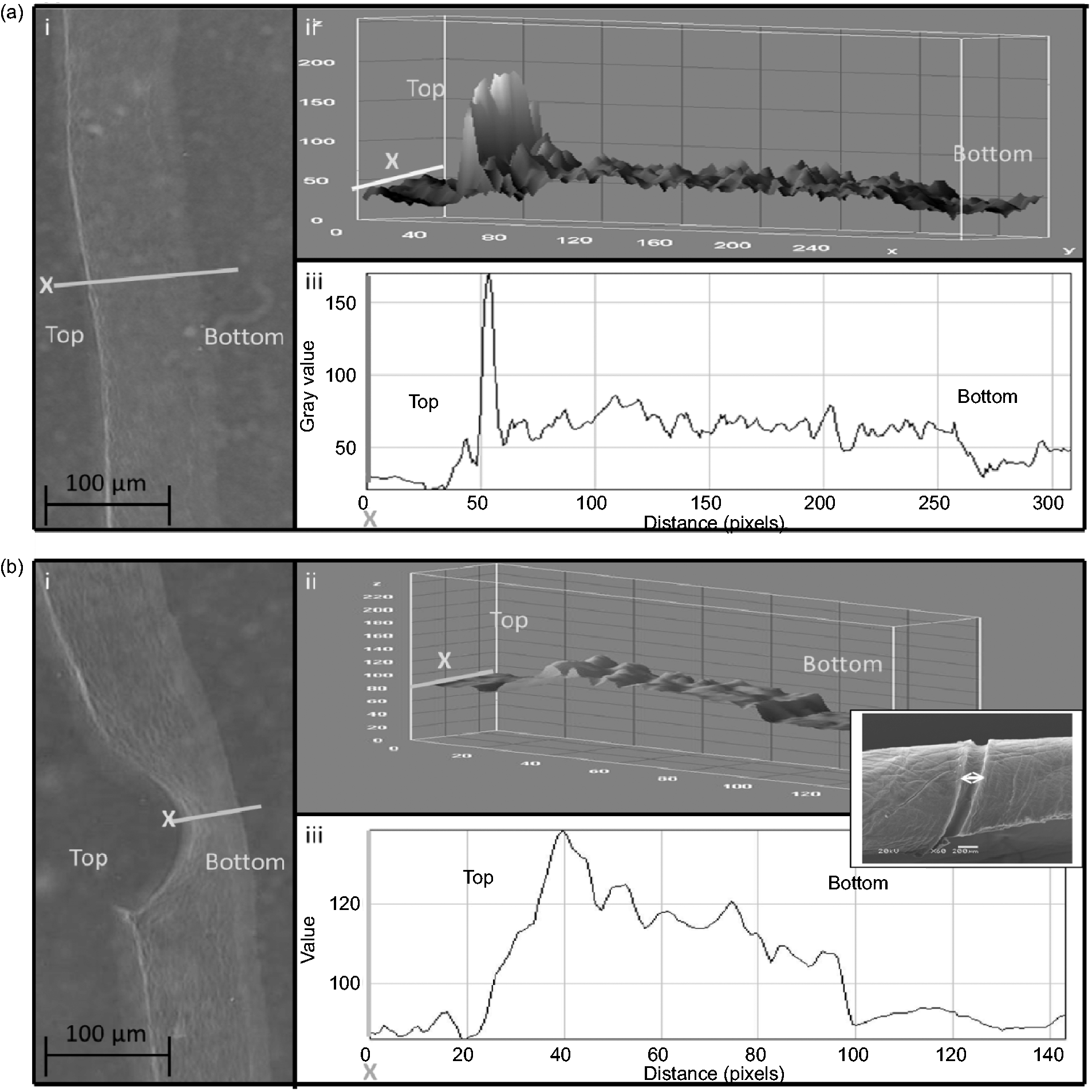
Template wires of 100 µm diameter, produced grooves of 118.3 ± 40 µm widths and 59.3 ± 20 µm depths, whilst 200 µm wires gave grooves of 236.3 ± 43 µm widths by 88.4 ± 27 µm depths. This represents 118% of expected maximum width for both wires, but 59 and 44%, respectively, of the expected groove depth, as reported previously. This represents a groove depth of around 50% that expected (or 50% infidelity), suggesting that more complex processes operate during collagen packing around the template surface.
Micro-moulding of topology influences collagen packing along the FLS
Image analysis was used to compare local, micro-variations in collagen density produced in the FLS by micro-moulding with the two template shapes. Non-patterned constructs, made without incorporation of a moulding template (i.e. with an entirely flat, compressed FLS), had no detectable differences in collagen density from one ROI to another along the FLS (Figure 3(a)). Micro-moulded constructs, on the other hand, had distinctive patterns of local collagen density at their FLS. Micro-moulding templates with a circular cross-section showed a single peak in collagen density at the base of the groove. Collagen density on either side of this peak gradually decreased towards the baseline, unpatterned areas of the collagen FLS (Figure 3(b)). In contrast, micro-moulding with rectangular cross-section templates produced two peaks of high density collagen located at the two internal corners of each groove. A small increase in density was seen in the flat bottom of these grooves but this was around half that at the groove corners (Figure 3(c)). The insets to Figure 3(bii) and (cii) compare these differences in terms of the mean percentage increase in density above that of the unpatterned baseline (i.e. the average density at least 50 µm away on either side of the micro-moulded groove feature). For rectangular grooves, there was a 16.0 ± 3.5% mean increase in density at the internal corners with no significant difference between densities at the two corners of one groove (means of 15.2 ± 4 and 16.9 ± 3%, respectively). The modest density increase in the floor of the groove was 7.7 ± 3%. For round cross-section templates, the increase in density at the base of the groove was 21.4 ± 4%. All of these differences were statistically significantly different from the baseline density (p < 0.05).
Density scans along the length of plain (a) and micro-moulded FLS surfaces using (b) round and (c) rectangular cross-section templates. In each section (a, b and c), panel (i) shows a representative micrograph and the track of scans made across the collagen layer and panel (ii) shows the graph of collagen density along the FLS. In all cases the arrow heads indicate positions of high collagen density. The inset graphs show the mean percentage increase in intensity of grooved regions (relative to collagen density in the non-groove area). b(ii): Plot of mean percentage intensity increase for round grooves (n = 7). c(ii): Plot of mean percentage intensity increase for rectangular grooves (N = 8). *P < 0.05 Groove base compared to the baselines in b(ii), and corners compared to the baseline in c(ii).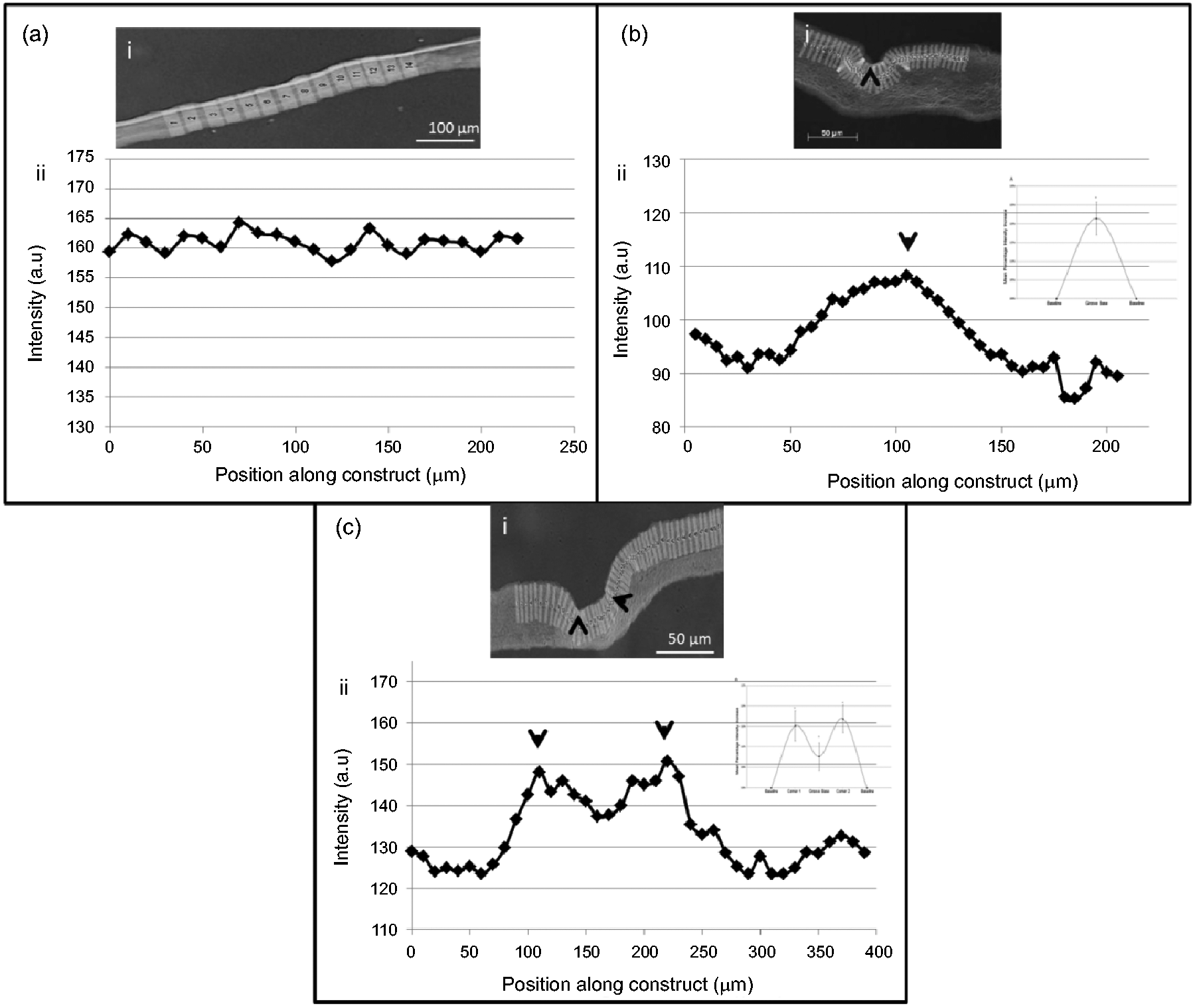
Figure 4 shows the scanning electron microscope (SEM) structure of two of the rectangular cross-section grooves, 25 and 100 µm (both 75 µm deep). This illustrates the structure and nature of the collagen lamellae which make up the layer and its FLS, together with the stable packing of collagen which was produced. An important observation was the internal micro-scale grooving pattern set into the flat floor of the grooves (inset micrographs). These ridges were perpendicular to the long axis of the groove and continued up the outer vertical walls, reflecting the likely fluid flow around and past the template during compression.
SEM images of patterned constructs, micro-moulded using 25 × 75 μm template (left-hand panel), and 100 × 75 μm template (right-hand panel). Upper row of images shows the overall, low magnification surface pattern of parallel grooves (arrows). Middle and lower rows of images show the transverse structure of individual grooves, with fine (<1 μm) ridges formed perpendicular to the groove axis in the floor and walls (lower high power images).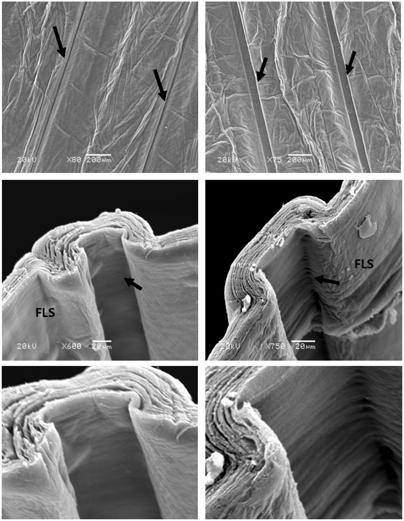
Converting stable grooves into closed channels
Once the pattern of collagen fibril deposition and micro-moulded groove formation was understood it was possible to develop a layer fabrication technique (bio-lamination) for producing continuous channels, running through the bulk collagen material. This was achieved by adding a second layer of collagen gel over the first, grooved surface to ‘roof’ the ‘groove’ and convert it into a channel. Figure 5 shows the result of this roofing step. In all the test groove sizes used here, the initial groove remained intact and did not fill with collagen solution, which initially seemed probable. Hence the grooved surfaces were converted by a simple, rapid lamination step into patent channels, suitable for the groove widths used here.
Once the rectangular profile groove had been formed in the first layer of compressed collagen a second layer was set over the top and it too was compressed in its turn, to produce a flat ‘roof’ to the groove, forming a closed channel. Representative histological images of these open channels are shown in pair (a), (b) (c) (transverse view, Sirius Red staining). Both the moulded and roofing layers were set as 10.6 mm deep gels. (a) 25 × 75 μm template, (b) 50 × 75 μm template, (c) 100 × 75 μm template. Solid arrows indicate the open area of the channel.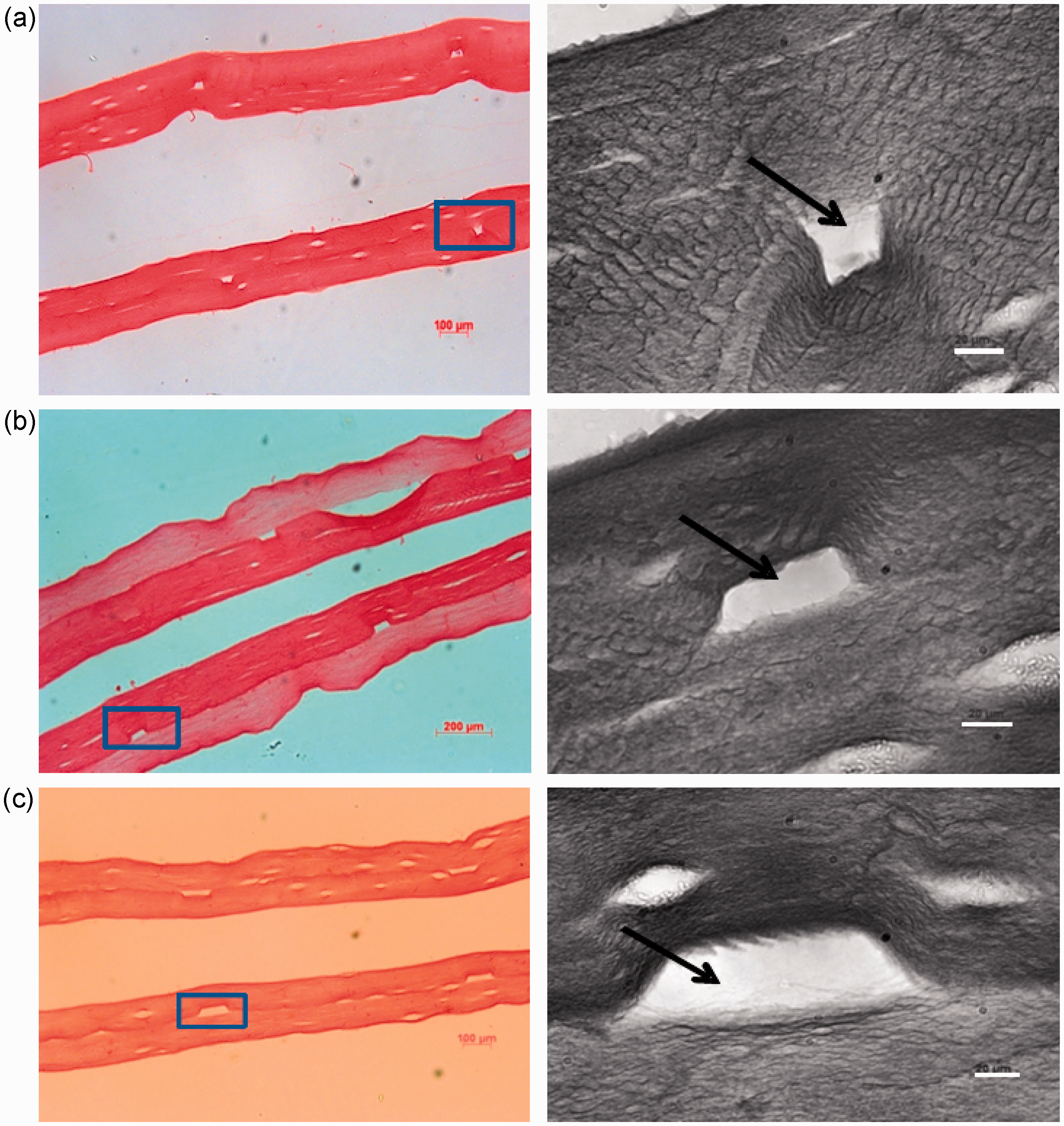
Furthermore, the two collagen layers became mechanically integrated during the compression, such that a stable interface was formed between the layers. As a result the channel roof remained firmly attached. Indeed, the interface between two such co-compressed layers was frequently hard to locate histologically. The mechanical stability of this co-compression interface was demonstrated using a simple agitation test. Placement of such two-layer, co-compressed constructs onto a standard orbital mixer (20 s of vigorous shaking) failed to separate the layers. In contrast, two independently compressed layers separated immediately, demonstrating that the co-compression of two layers produces structurally stable microchannels.
This represents a technique by which bulk, multilayer constructs of dense collagen can be made with a pre-formed honeycomb of capillary-scale channels. In effect the fidelity of this micro-moulding and roofing suggests that any pattern of channelling could be fabricated depending on the template used. Importantly, this is a rapid process, which can be carried out under cell-friendly conditions such that constructs can be cell seeded.
Figure 6 provides an analysis and comparison of groove and channel shape. Firstly, this illustrates the degree of depth fidelity of grooves made at the three widths of rectangular cross-section template. Bars of 25 and 50 µm produced around 50% of the expected depth whilst 100 µm wide bars gave slightly better fidelity, at 60%. It is important to note, however, that this groove depth was both useful and reproducible, at a predictable proportion of the template dimension. Figure 6(b) to (d) compares the width-to-depth dimensions of both micro-moulded grooves and the roofed channels which were then produced. It is clear from this that the ratio of depth to width which characterised initial grooves from each of the test templates was exactly retained once the groove was roofed into a channel. In other words, the addition of a second gel layer with subsequent compression did not fill in or deform the features significantly. Both of these would have been possible, either blocking the grooves (and so channels) with liquid collagen solution or distorting them under subsequent compression.
(a) Bar chart showing depth of the grooves as a percentage of expected value (depth of the rectangular cross-section templates). Seventy-five micrometres depth was taken as a 100%. Grooves were micro-moulded into the 10.6 mm deep collagen gels using templates with rungs of 25, 50 and 100 μm width. Bar charts comparing groove versus channel dimensions (depth and width), for 10.6 mm deep freshly cast collagen gels, for templates of (b) 100 × 75 μm, (c) 50 × 75 μm, (d) 25 × 75 μm template. Note the good width fidelity and depth infidelity. All dimensions were similar in both the initial grooves and the channels after they had been roofed with a second layer, indicating the stability of the grooves to the second compression.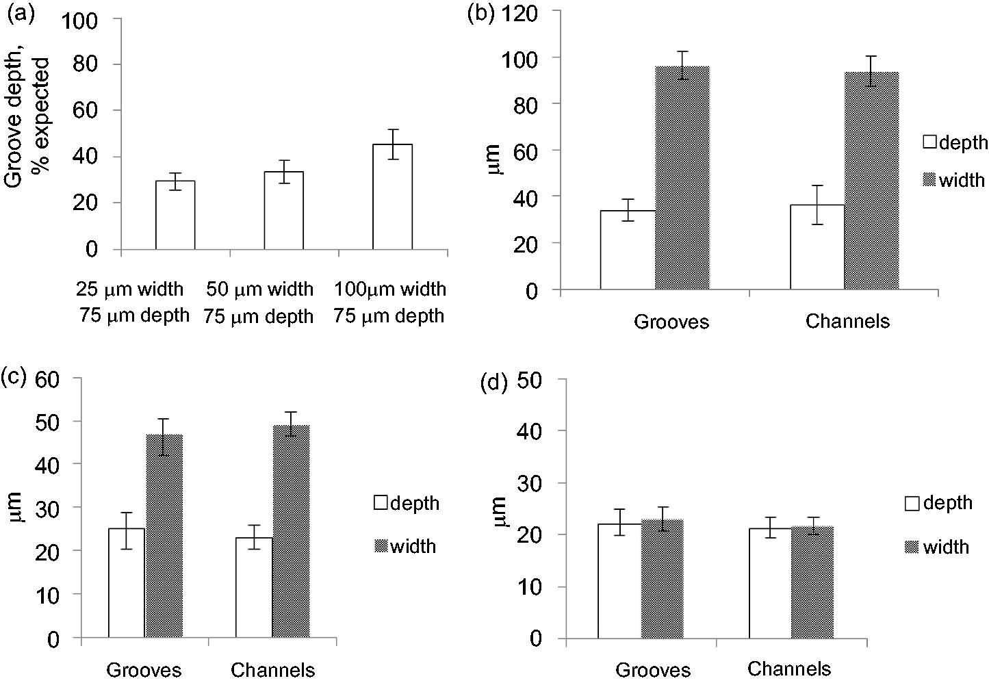
Whilst studies so far have established the stability and predictability of roofed channels it is also important to know the effect of cell-matrix remodelling. The final stage of this analysis tested the stability of micro-moulded channels using cell-seeded collagen in culture. Figure 7 shows the structure of the channels, and in particular the surrounding matrix, after 0 and 14 days in culture with human dermal fibroblasts. Channels clearly remained present and patent after culture and retained their initial shape. This was despite clear histological evidence for substantial cell remodelling of the bulk collagen construct matrix over that time period (Figure 7(c)), as reported previously.
4
The ability to seed cells onto the channel lumen and expand them to cover the internal surface, as a channel lining, was tested, using epithelial cells. In this case, the epithelial cells (HaCats) were first seeded onto the surface of the micro-moulding template. When this cell-carrying template was used to form roofed channels in a collagen construct, cells successfully transferred from the template to the groove/channel surface. These were subsequently expanded over the following 7 days in culture to produce an epithelial lining layer as shown in Figure 7(d).
SEM images of the fibroblast-populated microchannelled PC constructs immediately after assembly (a) and after 14 days in culture (b). Insets show the appearance of the grooves at the respective culture times (0 and 14 day) with the roofing layer peeled away. Fibroblasts within the collagen were not normally visible by SEM, but the technique does clearly show that the channel structure was effectively unaltered by the matrix remodelling of cells cultured over this period. (c) Histological section (H&E staining) showing internal matrix structure of constructs after 14 days remodelling by human dermal fibroblasts (contrast with the unremodelled appearance immediately after fabrication (Figure 5). (d) Histological (H&E) cross-section of a roofed channel seeded with HaCat epithelial cells and cultured for 7 days to expand into a cell-lining layer. The roof layer is above the dotted line and the grooved layer (1) is below.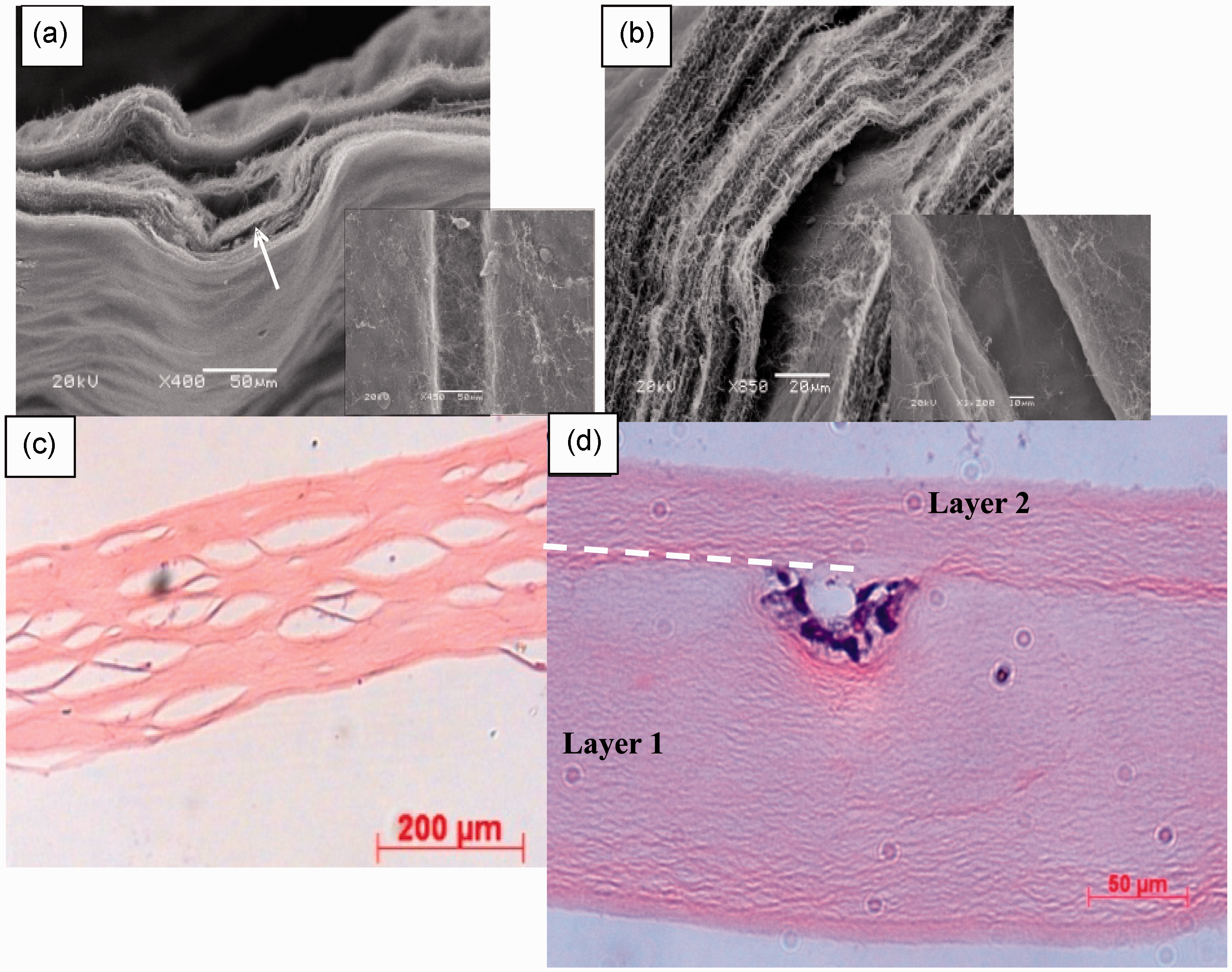
Discussion
Collagen is the most abundant protein in the vertebrate body, with particular importance in structural stability of tissues and the behaviour of resident cells. As we learn progressively more about using native collagen as a material for tissue fabrication the importance of techniques to generate internal structure, not least for deep cell perfusion, becomes more pressing. PC of collagen-cell gels has been developed as an effective method for rapid layer fabrication of tissues, comparable to 3D printing, without the printer.4,13,14 A key feature of the PC element is that fluid is expelled rapidly from the hyper-hydrated collagen gel. Since the gel deformation is plastic it is not surprising that surface patterns can be stably micro-moulded into the construct surfaces with suitably shaped templates, during the compression.4,6,15 Previous work has identified some basic features underpinning this technique, suggesting that the pattern and density of collagen fibril accumulation around the template is critical. The present study aimed to understand some of the mechanisms underlying fibril stabilisation of these surface topographies with a view to using them to form perfusion channels.
Using micro-densitometry analysis of collagen, deposited around embossing templates it was possible to identify specific differences associated with altered patterns of fluid outflow. We suggest that the mechanism of formation of these patterns may be explained, at least in part, by local splitting (bifurcation) of fluid flow as it is forced to go around the template (Figure 8). During PC, fluid flows, from the bottom of the gel, up and out into the absorbent plunger, but it seems likely that mobile collagen fibrils will be deposited at points where flow bifurcates around the non-permeable template. This would most likely be the case at the early stages of compression where the FLS is first forming and fibrils are most likely to be moved. Figure 8 illustrates this idea, suggesting why round cross-section templates have a single central density peak, whilst rectangular sections have densities at each corner. The same fluid flow pattern, across the axis of the template bar, would also explain the perpendicular ridges of aligned collagen in the floor of rectangular templates.
Collagen constructs (Sirius Red staining), showing the collagen deposition patterns around micro-moulded features within the FLS: (a) round cross-section groove, and (b) a construct embossed with a rectangular groove. In both cases the arrows indicate direction of hypothetical fluid flow, around the obstructing template at the FLS, during early compression. In both shapes the asterisk indicates the actual position of maximum collagen fibril deposition – associated with a predicted point where there will be a split in the fluid flow.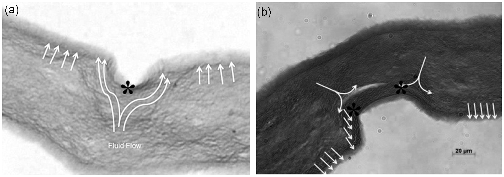
These density patterns, together with the importance of a stiff collagen-rich FLS in determining groove stability and depth fidelity (this study and Alekseeva et al. 6 ) have helped to inform the present approach to producing stable grooves. In turn, it has proved possible to build on these grooves by adding a second collagen layer to convert the grooves into channels or micro-capillaries. This approach to forming ‘internal’ perfusion channels had the potential to fail for a number of reasons. It seemed likely that the addition of fresh collagen solution to the freshly grooved layer (1) would flow into and fill in the grooves. However, it appears that the collagen viscosity and narrow width of these grooves prevents such infill through surface tension. It was also possible that compression of the layer (2) collagen onto the grooved surface would collapse the topography and obliterate the channel, but this too was not seen. The potential for the two layers to separate, after serial compression, so ‘un-roofing’ the groove was a real possibility but a simple study demonstrated that compressing the second layer into the first produced a degree of mechanical integration and interface stability. Finally, it is well known that fibroblasts within the compressed collagen, both in culture and in vivo4,16 gradually remodel the internal structure and this could result in loss of channel structure over a period of days. Again, it was possible to show that this remodelling did not result in loss of the channel structure.
In a final test, we seeded epithelial cells directly onto the (plastic polymer) surface of the moulding template in an attempt to ‘print-transfer’ cells into the groove and so into the channel. This was designed to test the idea that a lining layer of cells could be specifically transferred to the lumen only, and expanded to coat the channel surface, to mimic vascular channels. In this case, the kaptan polymer surface of the template, not surprisingly, appeared to be less cell adhesive than the collagen into which it was pressed. As a result live cells were effectively transferred to the groove surface and subsequently expanded to line the inner surface.
Understanding the mechanism of collagen and FLS moulding (and cell transfer) is a key step as its repetition with many serial multi-layers of collagen will generate unlimited micro-complexity within a single rapid fabrication process.
Conclusion
Clearly the ability to achieve a cell lining in this way, mimicking vascular capillaries, will be dependent on the cell type used. In principle, this demonstrates that tissue-like collagen constructs can be rapidly fabricated by micro-moulding and multi-layering, within a unified cell-friendly production process. It represents an alternative, novel form of 3D tissue fabrication, i.e. layer-by-layer ‘printing’, but without the printer. It establishes that micro-moulding can be incorporated into a rapid fabrication process to make internal µ-scale structures, including vascular-like capillaries. Importantly, the process is controllable and rapid (compared to ‘lost or soluble fibre’ techniques 14 ) and practical now, using living cells. This contrasts with conventional 3D printing, electro-spinning approaches17–19 or recapitulation of growth/tube formation of vascular endothelial cells,20,21 all of which have great potential but require more basic development.
Footnotes
Acknowledgements
We would like to thank Rosemary Drake (TAP Biosystems, UK) for her support and advice. Funded by Technology Strategy Board (TSB) and Engineering and Physical Sciences Research Council (EPSRC) (UK), and with additional support from the EU Framework 7 ‘BIODESIGN’ program. NST and TA contributed equally to this work.
Funding
This research was funded in part from the European Union (Framework 7, BIODESIGN programme) and from the Technology Strategy Board/EPSRC (RAFT programme).