
Abstract
The cardiac computed tomography (CT) practice guidelines provide an updated review of the technological improvements since the publication of the first Canadian Association of Radiologists (CAR) cardiac CT practice guidelines in 2009. An overview of the current evidence supporting the use of cardiac CT in the most common clinical scenarios, standards of practice to optimize patient preparation and safety as well as image quality are described. Coronary CT angiography (CCTA) is the focus of Part I. In Part II, an overview of cardiac CT for non-coronary indications that include valvular and pericardial imaging, tumour and mass evaluation, pulmonary vein imaging, and imaging of congenital heart disease for diagnosis and treatment monitoring are discussed. The guidelines are intended to be relevant for community hospitals and large academic centres with established cardiac CT imaging programs.
These Practice Guidelines have been reviewed and endorsed by the North American Society for Cardiovascular Imaging (NASCI).
Introduction
These cardiac computed tomography (CT) practice guidelines have incorporated technological improvements that have occurred since the last version of the Canadian Association of Radiologists’ (CAR) cardiac CT practice guidelines were published. 1 We provide an overview of the current evidence supporting the use of cardiac CT in the most common clinical scenarios, describing standards of practice to optimize patient preparation and safety as well as image quality. Coronary CT angiography (CCTA) is the focus of Part I. Here in Part II, we provide an overview of cardiac CT for non-coronary indications that include valvular and pericardial imaging, tumour and mass evaluation, pulmonary vein imaging, and imaging of congenital heart disease for diagnosis and treatment monitoring.
Recommendations included in these practice guidelines were compiled by a working group of Canadian cardiac imaging experts informed by a contemporary literature review that prioritized systematic reviews and randomized control trials or based on consensus expert opinion in the absence of high-quality studies. They are intended to be relevant for community hospitals, as well as large academic centres with established cardiac CT imaging programs.
Non-Coronary Cardiac CT
CT Guidance for Electrophysiology Procedure Planning
Left Atrium and Pulmonary Veins
Arrhythmogenic foci within the pulmonary veins (PV) are the most common source of ectopic beats that lead to atrial fibrillation. 2 Catheter ablation is recommended for patients with symptomatic paroxysmal or permanent atrial fibrillation, who are resistant to or intolerant of antiarrhythmic drugs, or who decline medical therapy. Success rates are greater than 80% in patients without underlying structural heart disease. 3 Complete isolation is required for successful ablation outcome.4,5 The success rate and occurrence of major complications is due in part to the complexity and anatomic variability of the left atrium and PV. 6
A detailed knowledge of the left atrium and PV anatomy is imperative for the electrophysiologist to ensure accurate targeting and planning during PV isolation (Figure 1).
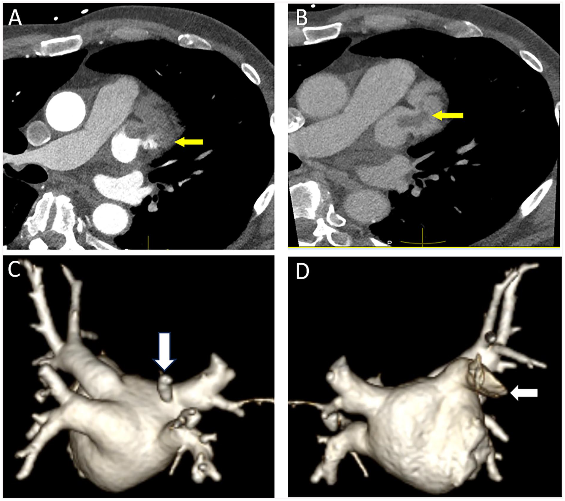
(A) Axial contrast-enhanced image showing non-opacification of the left atrial appendage which could be due to slow filling or the presence of a true thrombus in a 58-year-old man pre-atrial fibrillation ablation (arrow). (B) Delayed phase image in the same patients shows an oval hypodense filling defect surrounded by contrast consistent with thrombus (arrow). (C) 3D volume rendered reformat from a posterior view in a 77-year-old female with refractory atrial fibrillation demonstrating a normal variant separate pulmonary vein draining the superior segment of the right lower lobe that enters the left atrium in close proximity to the right superior pulmonary vein orifice (arrow). (D) 3D volume rendering from an anterior view demonstrating the left atrial appendage (arrow).
Cardiac CT is valuable to characterize posterior left atrial and PV anatomy (Figure 1C and D) accurately with and without ECG gating. 7 In comparison to other imaging modalities, CT is superior to fluoroscopy and transesophageal echocardiography to depict the number of PV ostia.8,9 CT offers the advantage of rapid data acquisition, decreased cardiac motion when ECG-gating is used and isotropic sets to allow multiplanar image reformats. Information concerning the number, size, and distance of the first branch to the pulmonary vein ostium, and the presence of anatomic PV variants are becoming less important to help select the size of the catheters used to perform the ablation procedure than in the past due to advances in electrophysiology technology. CT is also valuable to assess the dimensions of the left atrium, the presence of left atrial appendage thrombus (Figure 1A), anomalous pulmonary venous connections, the anatomic course of the esophagus relative to the posterior left atrial wall and PV, and any anomalies that may interfere with transeptal puncture.10,11
CT images can be fused with electro-anatomic maps and/or superimposed onto real time fluoroscopic images.12,13 Several studies have suggested that such fusion techniques may reduce procedure time, recurrence rates of atrial fibrillation, and fluoroscopic radiation exposure.14,15
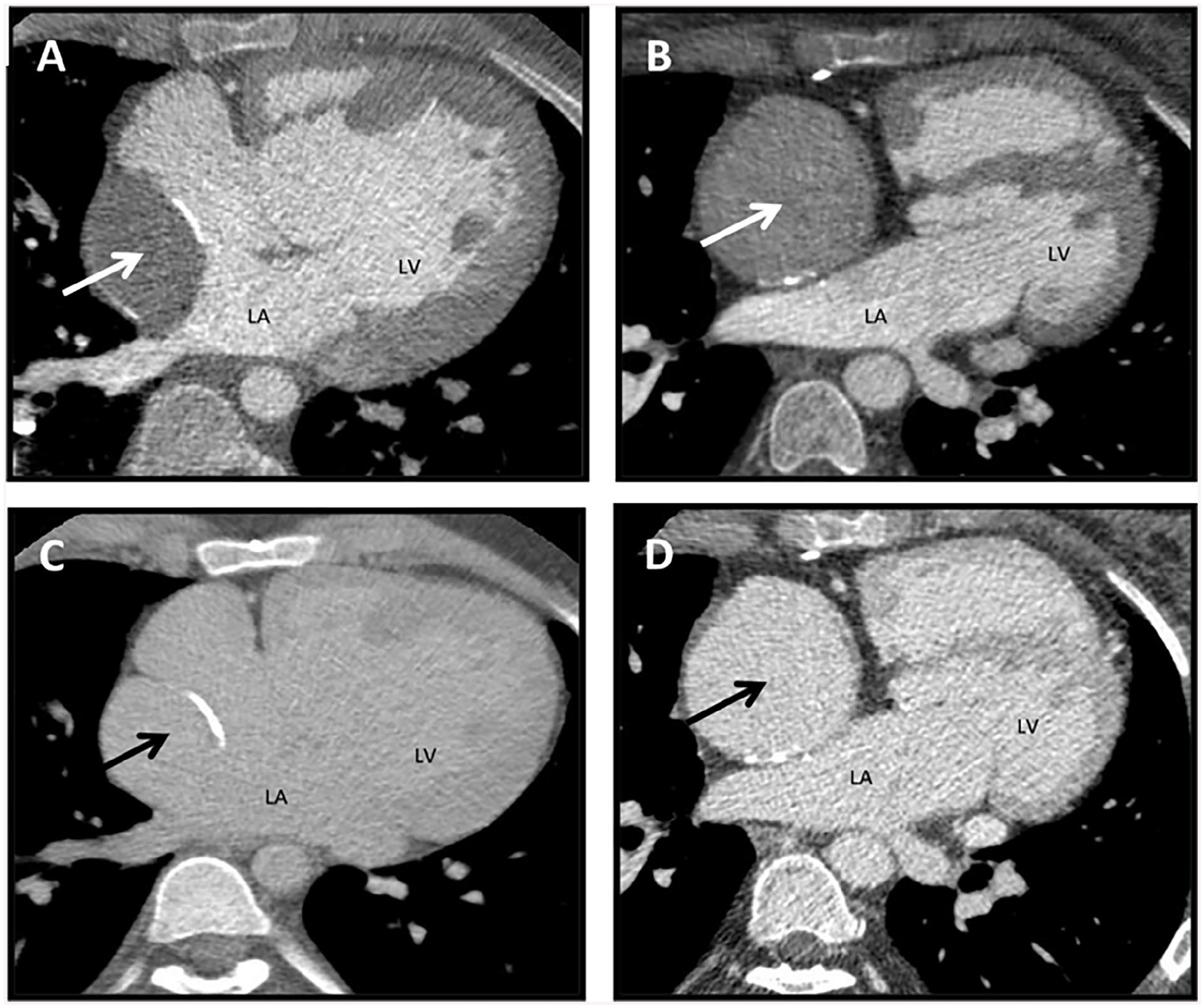
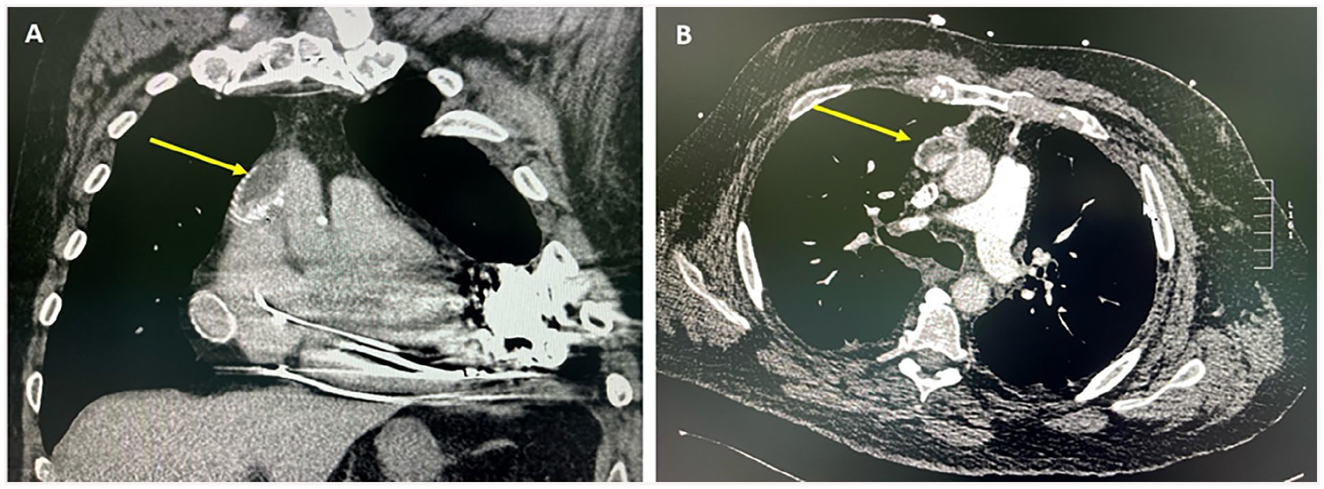
Finally, Cardiac CT is useful in the follow-up of patients after ablation therapy to assess for the development of rare complications, such as PV stenosis and esophageal injury leading to development of esophageal-atrial fistula (Figure 2).16,17
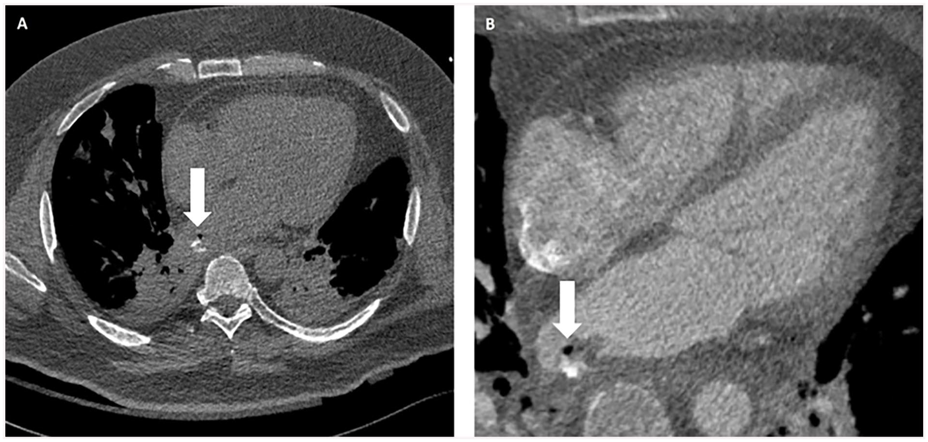
A 44-year-old male with esophageal injury after ablation therapy leading to esophageal-atrial fistula. (A) Chest CT with oral contrast shows air and oral contrast extravasation within the posterior aspect of the left atrium (arrow). (B) Cardiac CT with intravenous contrast shows esophageal thickening, air (arrow), and contrast extravasation within the posterior aspect of the left atrium.
Left Ventricular Ablation
Sustained ventricular tachycardia and ventricular fibrillation are manifestations of significant structural heart disease and are often associated with a high risk of sudden cardiac death. In the last 2 decades, radiofrequency catheter ablation has evolved into an effective treatment modality for patients with scar-related ventricular arrhythmias.18,19
The rationale for using cardiac CT for radiofrequency catheter ablation planning is to identify or exclude severe coronary stenosis that could contribute to ventricular arrhythmias. Cardiac CT can help identify the underlying cardiac coronary and venous anatomy, as well as epicardial fat thickness for optimal pre-procedural planning, especially if an epicardial approach is used. CT also allows a 3D model to be imported into the electro-anatomical mapping, including the coronary arteries, coronary sinus and sometimes the phrenic nerve, allowing intra-procedural visualization of these important anatomical structures.
Late iodine enhancement cardiac CT should be considered as an alternative to cardiac magnetic resonance imaging (MRI) in patients with contraindications to provide important information about myocardial scar that can be the source of ventricular tachycardia. It could potentially replace MRI in patients with ventricular arrhythmias because it can demonstrate severe coronary stenosis and myocardial fibrosis in a single examination. However, both radiation dose and the volume of iodinated contrast medium required are higher compared to coronary anatomy evaluation alone. The higher volume of contrast required also limits its clinical use for myocardial scar imaging in patients with severe renal failure.
Cardiac Vein Mapping
Patients with heart failure or advanced cardiomyopathy often undergo cardioverter defibrillator insertion or cardiac resynchronization therapy (CRT). 20 Imaging of the cardiac venous system is often helpful to plan the approach and access for CRT. In CRT, left ventricular pacing is achieved by positioning the left ventricular lead in one of the tributaries of the coronary sinus.20,21 The challenge of left ventricular lead implantation is the requirement for precise lead placement in the area where the electrical parameters are assumed to be maximal. Failure of left ventricular lead placement may be related to inability to cannulate the coronary sinus and lack of suitable side branches.
Wide anatomical variability of the cardiac venous system can pose challenges for CRT, hence the importance of pre-procedural imaging to define the anatomy. 22 Pre-procedural imaging with cardiac CT and 3D volume rendering provides detailed anatomical information regarding the coronary sinus and its tributaries that is critical for planning targeted left ventricular lead placement, shortening the procedural time thereby reducing radiation dose exposure. Pre-procedural cardiac CT helps with patient selection by excluding patients who have no suitable candidate veins, thereby avoiding an unsuccessful procedure. 23 CT is also used to evaluate complications such as lead perforation. However, beam hardening artifact can pose challenges to determine the exact position of the lead tip. Current iterative reconstruction metal artifact reduction algorithms can reduce beam hardening artifact and improve interpretation accuracy. 19
Ventricular Function
Left Ventricular Function
MRI is considered the gold standard for functional imaging. However, transthoracic echocardiography (TTE) is widely available and often used as a first-line imaging modality to assess biventricular function. When echocardiographic images are suboptimal and MRI cannot be performed due to patient factors such as claustrophobia or MRI contraindications, CT can be a reasonable alternative for biventricular functional evaluation. A meta-analysis of 12 studies showed no significant difference in calculated ejection fractions of CT, MRI, and TTE. 24 Cardiac CT is reproducible with good interobserver agreement owing to its true volumetric measurement (similar to MRI) without the geographic assumptions used in echocardiography. 25 The use of cardiac CT for functional measurement is limited by the need for full cardiac cycle radiation exposure and relatively lower temporal resolution compared to MRI or TTE, making it a less suitable modality for routine assessment. Studies have shown accurate and feasible low radiation dose techniques without the need for rate lowering medication that is often required in CCTA. 26
Right Ventricular Function
As stated above, volumetric coverage and full cardiac cycle imaging allows for accurate functional assessment. The 2010 ACCF/SCCT/ACR/AHA/ASE/ASNC/NASCI/SCAI/SCMR appropriate use criteria and 2015 ESC Guidelines designate CT as “Appropriate” for evaluation of the right ventricle predominant arrhythmogenic cardiomyopathy.27,28
Valvular Assessment: Native and Prosthetic Valves
Cardiac CT has evolved as a critical tool for the assessment and pre-operative planning of valvular heart disease. Aortic valve calcification scoring on non-contrast imaging can provide a flow independent measurement that correlates with stenosis severity. 29 It is particularly helpful in low flow, low gradient aortic stenosis on echocardiography. Transcatheter aortic valve replacement and percutaneous mitral valve replacement have become mainstays in the management of valvular disease. Both require extensive assessment with cardiac CT for annulus measurements, determining device suitability and access routes for implantation.
Cardiac CT provides complementary and detailed structural information regarding prosthetic valves. With an increasing prevalence of prosthetic valve implantation, imaging of their complications has also become important. Where echocardiography is limited by acoustic shadowing in the evaluation of prosthetic valves, cardiac CT does not have the same artifacts. With its high spatial resolution, cardiac CT can demonstrate many common complications such as valve dysfunction, leaflet thrombus, pannus formation, vegetations and root abscesses, in addition to evaluating para-valvular leaks. 30 CT can accurately determine the cause of prosthetic valve obstruction as compared to transesophageal echocardiography. 31
Cardiac CT is less useful for evaluating the severity of native valve stenosis or regurgitation. Planimetry of aortic valve stenosis can be achieved with CT but tends to overestimate valve area as compared to TTE. 32 Grading of severity of valvular regurgitation using cardiac CT is unreliable and not routinely performed.
Cardiac CT to Guide Transcatheter Interventions
Transcatheter Aortic Valve Replacement (TAVR)/Transcatheter Aortic Valve Implantation (TAVI)
Pre-Procedure Planning: Native Aortic Valve
Evidence from the PARTNER investigators has shown that patient outcomes from transcatheter placement of an aortic bioprosthetic valve for severe aortic stenosis is comparable to that of conventional surgical aortic valve replacement.33,34 While neither of these landmark trials used CT consistently for annular sizing pre-procedure, ECG-gated cardiac CT is now considered the gold standard for selection of valve size and determining procedural risk (Figure 3).
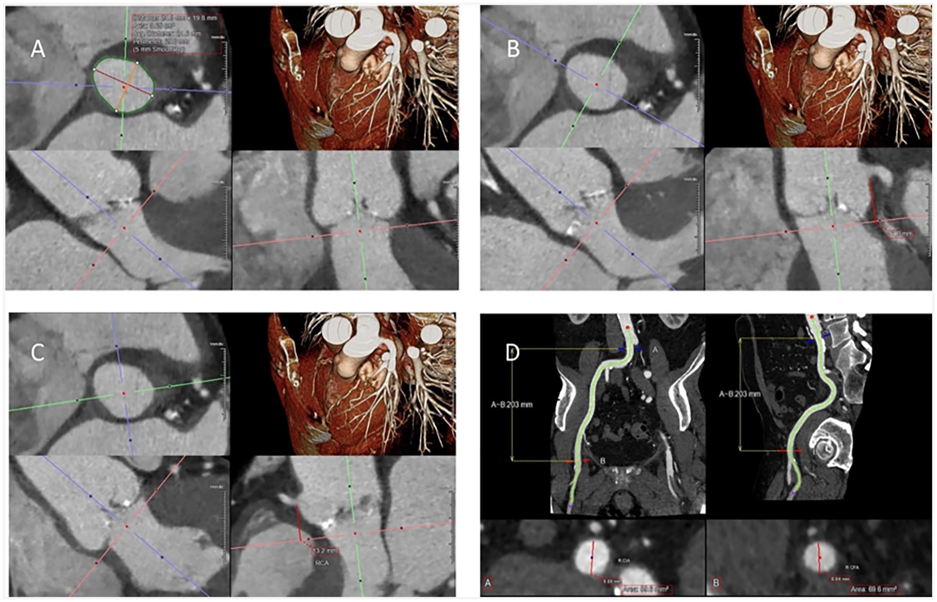
Standard multiplanar reformatted images performed in the evaluation of TAVR on CT. (A) Basal ring size assessment, typically during systole when the annulus is larger compared to diastole. (B) Left coronary height measurement. (C) Right coronary height measurement. (D) Right femoral/iliac access measurement using curved planar reformats at the point of access at the common femoral artery.
The complex shape of the aortic annulus can be reliably measured with CT. Whether it is a cross sectional area or perimeter derived diameter, CT can accurately determine annular dimensions and help select an appropriate valve size that will limit risk of annular rupture, paravalvular leak, and valve embolization. Various sizing charts help with prosthesis selection and sizing, largely driven by basal ring measurements provided on CT. 35 Valve oversizing of 5% to 15% is generally preferred to help balance the risk of paravalvular leak and embolization versus annular injury and rupture.
Generally, a full cardiac cycle should be acquired. However, ECG tube current modulation, with limitation of tube current outside of the systolic phases (20%-40% of the R-R interval) should be considered as the annulus is generally largest in systole and it is this measurement that should be provided for valve sizing. 36 In rare cases, reverse dynamism of the annulus can occur, particularly in those patients with septal hypertrophy. For this reason, diastolic phases may also be helpful for optimal sizing.
Annular rupture is a rare event (0.9%).33,34,37 Selection of an appropriately sized valve is essential to avoid complications such as annular rupture, significant paravalvular leak or valve embolization. Adverse root features are also demonstrated on CT such as significant protruding subvalvular calcification in the aortic valve implant zone. It is important to report the extent (mild, moderate, or severe) and location (in relation to which aortic valve cusps) of subvalvular calcification. 38
Additional root anatomy, namely coronary ostial height (as measured perpendicular from the annular plane, Figure 3), sinus of Valsalva size (commissure to cusp), and sinotubular junction (STJ) size and height should also be recorded in all CTs for TAVR planning. Low coronary ostial height (<12 mm) and small sinus of Valsalva diameters (<30 mm) are associated with increased risk of coronary occlusion. 39 A small STJ, particularly for balloon expandable valves, can be associated with risk of STJ injury. It is important to consider what valve size will likely be selected (based on basal ring assessment) when determining what size of STJ would be considered at higher risk. 40
Imaging should also include the coverage of the subclavian arteries and caudally to cover to the level of the lesser trochanter/profunda femoris artery. The advent of CT for TAVR planning initially gained a foothold with accurate evaluation of the iliofemoral systems to ensure safe peripheral vascular access and device delivery. The minimal diameters, including comment on presence of circumferential vascular calcification and minimum luminal diameters (also at access point, usually at the common femoral artery) should be provided bilaterally (Figure 3). A subjective assessment of vessel tortuosity is also important. It is these factors that are felt to be predictive of access/vascular injury by the Valve Academic Research Consortium group. 41
If femoral access is unfavourable, similar measures of the right and left subclavian arteries and carotid arteries should be included in the report as alternative points of access.
In cases of suspected low flow low gradient severe aortic valve stenosis (where peak and mean gradients across the aortic valve by echocardiography are underestimating severity of stenosis often due to reduced left ventricular ejection fraction), the aortic valve calcium score (using the same software as coronary calcium scoring) may be helpful to confirm severe aortic valve stenosis.
Pre-Procedure Planning: Valve in Valve (ViV) Procedure
Placement of a transcatheter valve can also be performed in a degenerated/failing bioprosthetic surgical valve, also known as valve in valve transcatheter aortic valve implantation (ViV TAVI). CT protocol for assessment pre-procedure in ViV cases is the same as for native valves, except dynamism of the annulus is not an issue with a surgically replaced annulus, and thus ECG tube current modulation with full cardiac cycle imaging is not always necessary.
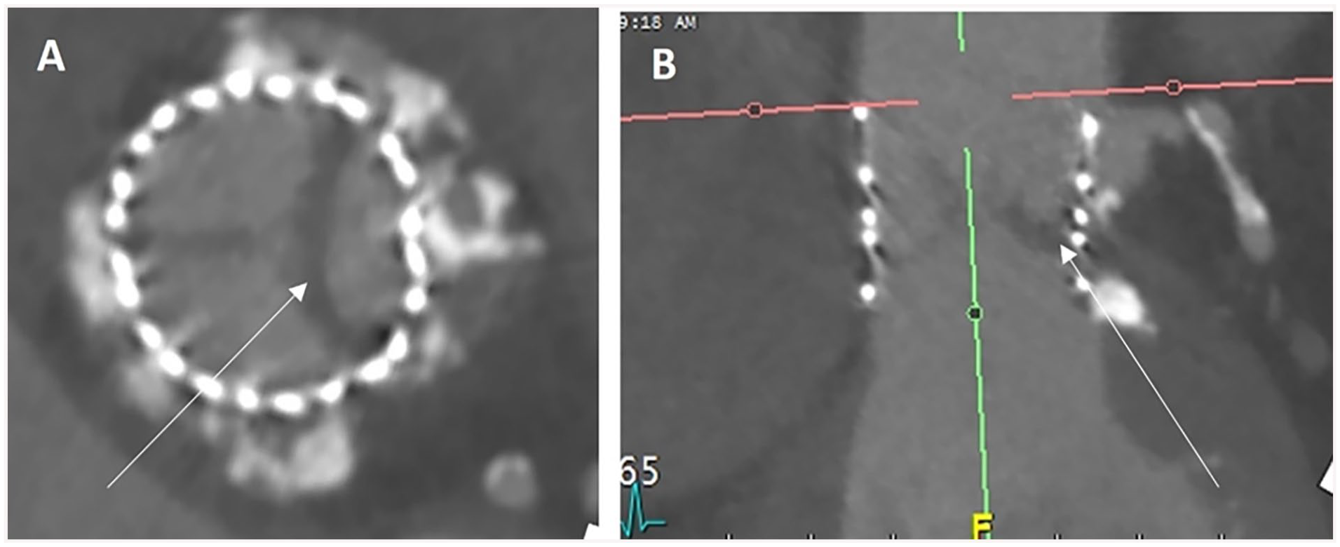
An application is available to help with selection of TAVI model and size for ViV procedure. 42 It is essential to know the make and model of the surgical valve to appropriately size and determine which TAVR model is appropriate. 43 This information can come from surgical records, but if necessary, can also be determined from CT appearance in most cases (Figure 4).
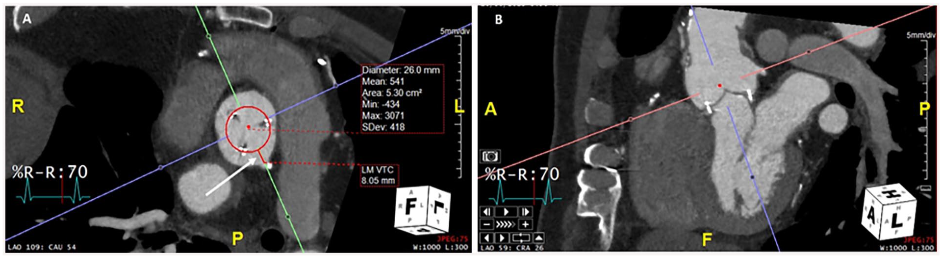
Planning CT images for a valve-in-valve TAVI. 27 mm Perimount Magna 3000 surgical valve, with a 26 mm TAVI modelled. (A) demonstrates a VTC distance (white arrow) of 8.05 mm to the left main coronary artery ostium, indicating a low risk of coronary obstruction. Corresponding oblique reformat (B) denotes the left main coronary ostium.
Once a TAVR size and model have been determined, considerations for ViV planning with CT are focused on determining the risk of coronary obstruction, and post procedure access to the coronary vessels. The bioprosthetic cusps will be displaced above the surgical valve annulus creating a cylindrical shape and potentially sequestering the sinuses at the STJ and thus occlude the coronaries (if the axial distance from the periphery of the implanted TAVR is less than 4 mm to the inferior aspect of the coronary ostium, generally referred to as the valve to coronary distance VTC, Figure 4).44,45 Coronary occlusion is not an issue when the coronary ostium is above the level of the displaced leaflets or cusps, which can be estimated by the cranial extent of a stented surgical valve. If the displaced leaflets could extend all the way to the STJ then the perpendicular distance from the simulated TAVR to the STJ should also be measured. A distance from the valve to STJ of <3.5 mm can indicate higher risk of coronary occlusion (Figure 4).44,45
Post-Procedure Follow-Up
Following TAVR, imaging with CT also plays an important role in assessment of expansion, complications and in the evaluation of hypoattenuating leaflet thickening (HALT), arrows (Figure 5).
Findings of high attenuation leaflet thickening (HALT) seen in the diastolic phase at the left cusp (white arrows images (A) and (B)) of a TAVR 3 months post implantation with elevated gradients on echocardiogram.
Post TAVR imaging should be done with ECG gating and should include a full cardiac cycle. The use of ECG tube current modulation is not necessary as dynamism is not expected post-implantation, and the evaluation of HALT often requires multiple high-quality phases for accurate assessment. Coverage can generally be limited to the heart unless peripheral vascular injury is suspected and requires imaging. The severity of HALT should be reported, as should restriction of leaflet motion (thus the need for full cardiac cycle imaging) (Figure 5). 46
Transcatheter Mitral Valve Replacement (TMVR)
Percutaneous mitral valve intervention can consist of mitral valve repair techniques such as MitraClip or true percutaneous replacement akin to TAVR. Much like TAVR, percutaneous replacement of the mitral valve extensively uses CT for pre-procedure planning. The complex saddle shape of the annulus can be simplified into a “D” shape in a 2-dimensional plane on CT to assist in selection of TMVR size. 47 CT protocol for TMVR planning is similar to TAVR, requiring ECG gating and full cardiac cycle acquisition. Since vascular access for these procedures is venous, delayed imaging of the abdomen and pelvis to the level of the femoral heads is required. A key component with CT planning for TMVR is determination of the “neo- left ventricular outflow tract” size, which is essential in prediction of subvalvular left ventricular outflow tract obstruction risk related to TMV implantation (Figure 6). 48
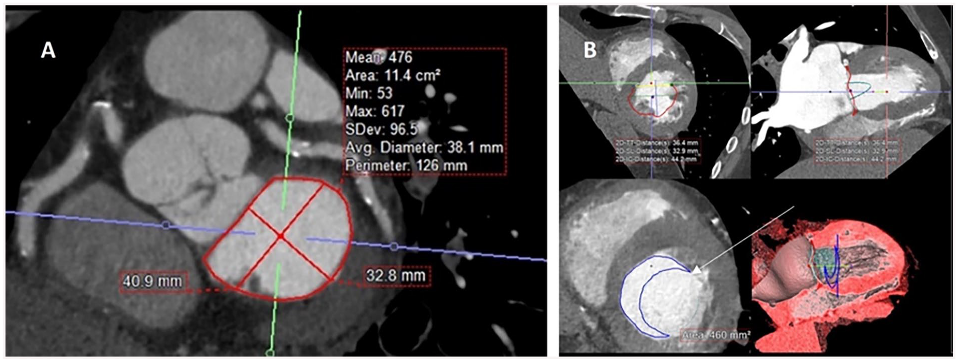
Multiplanar reformatted images of the heart for TMVR planning. (A) demonstrates the classic “D-annulus,” (B) model placement of a TMVR with the neo-LVOT depicted by the crescentic blue outline (arrow).
Transcatheter Tricuspid Valve Replacement (TTVR)
CT can also play a role in planning for percutaneous tricuspid valve interventions. The acquisition technique requires different contrast timing to allow evaluation of the right atrium and right ventricle. 49 ECG gating is still essential. Percutaneous interventions for the tricuspid valve are numerous, including both techniques to alter the tricuspid valve in an attempt to improve function and complete percutaneous replacement. 50 For TTVR, CT can be used akin to TAVR and TMVR in determination of appropriate valve size. 50
Transcatheter Pulmonary Valve Replacement (TPVR)
Cardiac CT also has an important role in pre-procedural planning for transcatheter pulmonary valve replacement (TPVR). 51 While initially performed for congenital heart disease patients with dysfunctional right ventricle to pulmonary artery conduits, 52 newer valves have been designed for patients with pulmonary regurgitation who have native or surgically-repaired right ventricular outflow tracts (RVOT).53,54 TPVR has also been performed for patients with dysfunctional surgical bioprosthetic valves. 55 CT is used to assess RVOT, pulmonary valve, and pulmonary artery morphology; conduit morphology and patency; and relationship of the RVOT or conduit to the coronary arteries to inform patient selection and device sizing. 51
Left Atrial Appendage (LAA) Closure and Other Plugs and Baskets
The left atrial appendage is a common site of thrombus formation in patients with atrial fibrillation. Transcatheter left atrial appendage closure is an alternative to long-term anticoagulation therapy in selected patients who have an increased risk for stroke or bleeding. Transesophageal echocardiography is the reference modality to assess the anatomy of the left atrial appendage and to provide intraprocedural guidance. However, CT has emerged as a less-invasive alternative for pre- and post-procedural imaging. ECG-gated cardiac imaging is increasingly being used for assessment of the left atrium and left atrial appendage due to high spatial and temporal resolution. Preprocedural imaging is key to identifying contraindications, accurately sizing the device, and minimizing complications. CT is comparable to transesophageal echocardiography for exclusion of thrombus, but is superior for the delineation of complex left atrial appendage anatomy, measurement for device sizing, and evaluation of pulmonary venous and extracardiac structures. 56 Post-procedural CT evaluation confirms correct positioning of device, helps to identify device embolization and total occlusion of the left atrial appendage. Also, CT has greater sensitivity to show peri-device leak.
Many other implantable closure devices can be used to close shunts (ie, atrial septal defect, ventricular septal defect, patent foramen ovale, or patent ductus arteriosus). 57
Cardiac Masses
Cardiac CT can be used for mass evaluation namely to differentiate tumours from thrombi, and to define the location and extent of cardiac tumours. Thrombi do not demonstrate internal enhancement and ventricular thrombi typically have lower density (<65 HU) compared to enhancing myocardium. 58 For cardiac tumours, non-contrast, arterial and delayed phase imaging are often helpful to determine contrast enhancement (Figure 7). Retrospective ECG-gating and full cardiac cycle imaging may be required for masses involving the valves. For evaluation of thrombi in the left atrial appendage, priming boluses or delayed phase imaging are often required to differentiate slow flow from true thrombi. 59 Atrial thrombi tend to be lower density compared to myocardium, similar to ventricular thrombi. In cases of severely dilated left atria, prone imaging facilitates contrast opacification of the anterior aspect of the left atrial appendage that may be sub-optimally opacified on initial scans due to poor atrial function and stasis.
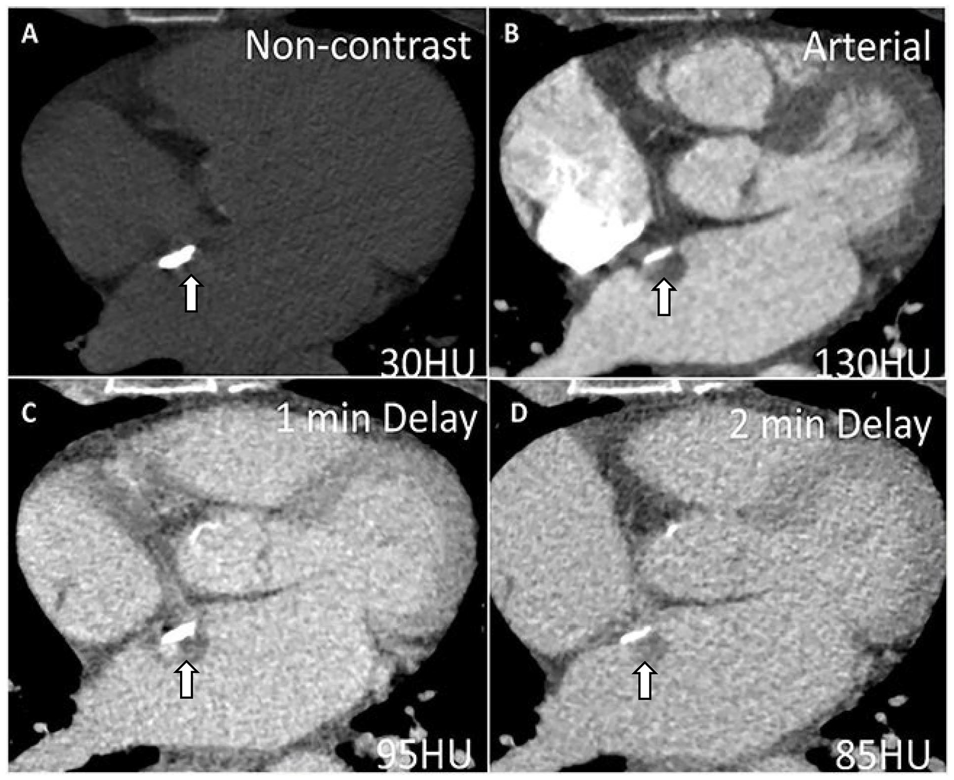
A 42-year-old woman with a mass attached to the interatrial septum first detected on TTE (not shown). Cardiac CT technique to differentiate tumour from thrombus involves imaging the mass on (A) non-contrast images, (B) arterial and at least one delayed phase (60 seconds or greater). In this case, the density of the mass increased from 30 HU to 130 HU on arterial phase scanning with mild washout characterized by density measurements of 95 and 85 HU on (C) 1-minute and (D) 2-minute delayed phase imaging, respectively. The presence of enhancement and washout supports the diagnosis of a small neoplasm such as a myxoma (shown by the arrows). Note the calcification along the interatrial septum.
Pericardial Disease
Cardiac CT is helpful to identify pericardial calcifications or thickening, and pericardial fluid that can guide management with respect to planning pericardiocentesis and insertion of pericardial drains. Pericardial masses from primary malignancies or metastatic disease can be imaged using contrast-enhanced cardiac CT to determine invasion of mediastinal structures and resectability. Pericardial constriction is suggested by the presence of pericardial thickening and/or calcification, dilated inferior vena cava and atria, as well as tubular configuration of the ventricles. Respirophasic septal shifting is a finding supportive of constrictive physiology on cardiac CT but requires retrospective ECG-gating to image the entire cardiac cycle and results in relatively higher radiation dose compared to prospectively ECG-triggered studies. Cardiac MRI, TTE, and catheter angiography are more often used in the evaluation of constrictive physiology compared to cardiac CT. 60 Pericarditis, pericardial cysts, and absent pericardium are also well depicted using cardiac CT.
Congenital Heart Disease
MRI is the primary modality for evaluation of adults with congenital heart disease (Figure 8). It is the reference standard for ventricular size and function, often providing important additional information to echocardiography. 61 Cardiac CT is performed when MRI is contraindicated such as with non-MRI conditional pacemakers, defibrillators, other implantable devices or when there are extensive metallic coils, stents, or other devices that preclude adequate visualization of key anatomic structures due to MRI susceptibility artifact. 62 There may be patient factors such as severe claustrophobia that also limit MRI use. CT is an alternative to MRI due to the generally shorter scan times and a wider bore that is often more tolerable for patients with claustrophobia. Due to superior spatial resolution of CT, it is often used for imaging coronary artery anomalies, coronary artery proximity to pulmonary arteries prior to endovascular pulmonary valve interventions or to rule out obstructive coronary artery disease. CT can also assess ventricular function as an alternative to MRI and transthoracic echocardiography. Cardiac CT is often used when there is a need to image the airways and lung parenchyma. It is also an alternative to MRI for evaluation of aorto-pulmonary collaterals, veno-venous collaterals, pulmonary arteries and veins. 61
Cardiac CT for Adult Congenital Heart Disease in 2 Fontan patients. (A) 29-year-old woman with extra-cardiac Fontan that is unopacified during an early arterial phase image (arrow). (C) More delayed imaging at 180 seconds shows homogeneous opacification of the extra-cardiac Fontan (arrow) with no evidence of thrombus. Delayed imaging is often required to avoid mixing artifacts from unopacified blood coming from the inferior vena cava. (B) 26-year-old male with classic Fontan that is unopacified (arrow) during an early arterial phase image. (D) 90-second delay shows complete homogenous opacification of the Fontan (arrow) with no evidence of thrombus.
In patients with bicuspid valve aortopathy or genetic aortopathies such as Loeys-Dietz or Marfan syndrome, cardiac CT is valuable to establish baseline and surveillance aortic dimensions from the aortic root to the aortic bifurcation. Cardiac gating is required for accurate aortic root measurements. However, in patients with isolated coarctation without associated bicuspid valve or root dilatation, non-gated CTA can be completed as the proximal descending aorta is affected less by cardiac pulsation compared to the aortic root. 63 CT can also demonstrate associated Marfan syndrome findings such as scoliosis, pectus excavatum deformity, or dural ectasia. Disadvantages include use of intravenous contrast and radiation, but recent technological advancements have facilitated significant reductions in both. 63
Left Ventricular Assist Device (LVAD), Right Ventricular Assist Device (RVAD), and Other Devices
Ventricular assist devices, including left ventricular assist devices (LVADs) (Figure 9), and less common, right ventricular assist devices (RVADs) and biventricular assist devices (BiVADS), can be used in patients with advanced heart failure as a bridge to heart transplant, myocardial recovery, or as a destination therapy for patients who are ineligible for transplantation.64,65 Mechanical device components include the pump, inflow and outflow cannulas, drivelines, and external controller. An LVAD usually consists of an inflow cannula which should be directed into the left ventricular cavity, an outflow cannula inserted into the ascending aorta, and a pump connecting them both. In an RVAD, inflow and outflow cannulas are usually anastomosed to the right atrium or ventricle and the pulmonary artery, respectively. 66 While echocardiography is the mainstay for evaluation of ventricular assist devices and is used for routine surveillance and adjustment of device settings, CT can be used for preoperative planning of position of the cannulae and for detection of complications as described below (Figure 9). 67
58-year-old male with left ventricular assist device (Heartmate 3) for severe heart failure. (A) and (B) Chest CT (coronal and axial views) shows filling defect within the outflow consistent with partial thrombosis (arrows).
Cardiac CT is used for preoperative evaluation to assess cardiac anatomy, sternal proximity of device components and the native heart for redo surgery. Ascending aorta and arch calcification are evaluated using CT for outflow graft positioning. Imaging the left ventricular apex, evaluating for left ventricular thrombus or calcification is relevant for determining the location for insertion of inflow cannula. Evaluation of cardiac dimensions is also important for proper planning of pump and driveline positioning.
Cardiac CT should be performed with retrospective ECG-gating with cine imaging of the heart reformatted in short axis and multiple long-axis planes to assess cardiac motion and dynamic positioning of the inflow cannula. 67 The field of view should include the aortic arch to include the outflow cannula, with an extended field of view through the abdomen to include the pump and power cord exiting through the skin. Use of a metal artifact reduction reconstruction algorithm is recommended. 67
Cardiac CT is also used to evaluate complications related to ventricular assist devices. Early post-operative complications include cannula obstruction, hemorrhage, and tamponade. 67 CT is particularly helpful in assessing the outflow cannula as it is not well assessed using echocardiography. Complications include kinking of the outflow cannula or tearing of the anastomosis. Late complications include thrombus formation (Figure 9) including thrombus adherent to the cannula or in low-flow areas such as the left atrial appendage, aortic valve stenosis, aortic valve insufficiency, and infection. Infection occurs in 14% to 72% of patients and can be seen as gas and fluid collections surrounding the pump, power cord, and cannulae. 67 Right heart failure can occur as an early or late complication and right ventricular volume and function can be assessed on cine CT images. 68 Pleural, abdominal, and vascular complications can also be assessed.69,70 Temporary devices are also available such as Impella or extra-corporal membrane oxygenation (ECMO). CT can help evaluate peripheral access required for insertion of these devices.
Pacemaker/Implantable Cardioverter Defibrillators (ICD) Lead Evaluation
Permanent pacemakers, cardiac resynchronization therapy (CRT) capable devices, and implantable cardioverter defibrillators (ICDs) are widely used to treat a variety of heart rhythm abnormalities, heart failure, and conditions leading to high risk of sudden cardiac death. 71 One of the potential complications of device implantation is lead-related cardiac perforation which occurs in less than 1% of cases and is associated with increased morbidity and mortality (Figure 10).72-74 The clinical presentation of lead perforation can be acute, subacute, or delayed. This may suspected due to device malfunction, sometimes identified on interrogation.75,76 Management may require percutaneous or surgical lead extraction.
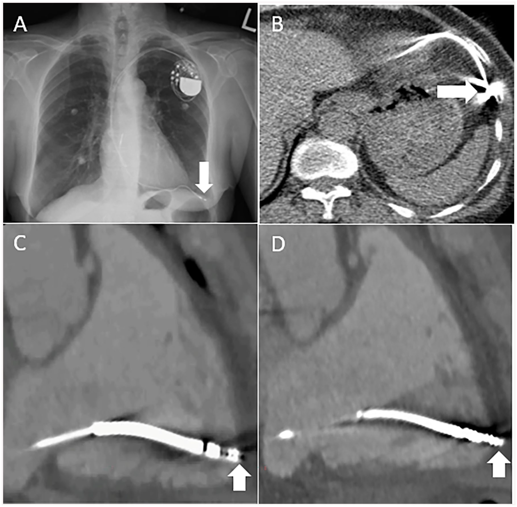
(A) Posteroanterior chest radiograph in a 77-year-old-male with acute chest pain, 2 years after pacemaker lead insertion demonstrating lead perforation beyond the heart (arrow). (B) Axial chest CT image in the same patient showing lead tip perforation beyond the right ventricular myocardium (arrow). The lead tip is abutting left anterior chest wall and adjacent to the left anterior hemidiaphragm. (C) 65-year-old-man with chest pain after defibrillator lead insertion. 3-chamber reformat of the right ventricle from a contrast-enhanced cardiac CT during ventricular diastole demonstrating defibrillator lead tip at the edge of the right ventricular myocardium, not clearly perforated (arrow). However, during ventricular systole, the defibrillator lead tip is seen beyond the right ventricular myocardium within the epicardial fat consistent with microperforation (arrow). Full cardiac cycle imaging is important to detect lead microperforations that are often seen best during ventricular systole, and they may occur without pericardial effusions or epicardial fat stranding.
In the past, device lead evaluation was performed with a combination of echocardiogram, fluoroscopy, and chest X-ray, each with inherent limitations in evaluating the relationship between the lead, the myocardium, and pericardium. Recently, cardiac CT has been described as the imaging modality of choice for the evaluation of lead perforation due to superior accuracy, sensitivity, and specificity compared to other imaging modalities (Figure 10). 77 Cardiac CT provides important information about the number of leads, and their relationship to the vasculature, myocardium, pericardium, chest wall and surrounding structures, as well as characterizing the presence and size of pericardial and pleural effusions.78,79 Motion and metallic lead artifacts are important impediments to diagnostic accuracy of CT, particularly when evaluating lead tip position. Retrospective ECG-gating can help reduce lead tip motion artifact. Imaging throughout the cardiac cycle is important to detect microperforations that may only be seen during ventricular systole (Figure 10). A contrast injection protocol (ie, biphasic) that opacifies both right and left ventricles is desirable. Current iterative reconstruction metal artifact reduction algorithms, multiplanar reconstructions, and dual energy CT protocols can be used to minimize beam hardening artifact from metal. 80 Cardiac CT can also facilitate pre-procedure lead extraction planning with assessment for venous stenosis or occlusion, abnormal cardiac anatomy, and the presence of vascular thrombi or adhesions.81,82
Incidental Non-Cardiac Findings
Cardiac CT includes multiple structures and organ systems in the field of view other than the heart, with frequent detection of incidental non-cardiac findings (INCF). The majority of INCF are not clinically significant. However, a minority of INCF will require follow-up or changes in management, with associated costs. A prior retrospective study identified incidental non-cardiac findings in 600/1713 patients; of the INCFs, 70% were insignificant, 25% indeterminate, and 5% were significant. 83 A meta-analysis found that 44% of patients undergoing cardiac CT have at least one non-cardiac finding. 84 In a separate meta-analysis that included 13 studies and 11 703 patients, acute life-threatening INCF were identified on coronary CT in 2% and malignancy was identified in 0.3%. 85
All images acquired should be reconstructed, sent to PACS, and evaluated by the interpreting physician. Non-cardiac structures that are typically included in the field of view include the lung parenchyma, mediastinum, aorta, pulmonary arteries, upper abdomen, chest wall, and bones. When INCF are identified, management recommendations should follow established guidelines when available.
Within lung parenchyma, incidental findings on cardiac CT include lung nodules, atelectasis, interstitial lung disease, and rarely lung cancer due to shared risk factors between atherosclerotic disease and malignancy (including smoking). Lung nodules are identified in 14% of patients undergoing CCTA 86 and can be evaluated using the updated Fleischner Society Guidelines for managing incidental pulmonary nodules. 87
Incidental findings in the mediastinum include lymphadenopathy, thymic masses, and hiatal hernias. Enlarged mediastinal lymph nodes may be identified in up to 2% of patients undergoing cardiac CT. 88 Hiatal hernias are also common. While frequently asymptomatic, they can be an alternate cause for the patient’s symptoms including chest pain and are therefore important to include in the report.
Although rare, aortic dissection is a potentially lethal INCF identified in approximately 1% of patients undergoing cardiac CT for acute chest pain. 89 Other potential vascular causes for chest pain include pulmonary embolism, identified in 0.3% of patients in the SCOT-HEART study. 90
Other non-cardiac structures that should be evaluated on cardiac CT include the visualized upper abdomen (including portions of the liver and kidneys), the chest wall, and bones. Degenerative changes in the spine are relatively common in older patients undergoing coronary CT. Rib fractures can be an alternative cause for the patient’s chest pain, along with compression fractures in the spine.
Conclusion
These practice guidelines focused on non-coronary indications have been revised to include technological innovations relevant to cardiac CT since the previous guidelines were published in 2009. To maintain alignment with future iterations of international practice guidelines and new technological advancements in both CT scanner hardware and software, these practice guidelines will continue to undergo revisions to maintain their relevance for both clinical practice in community hospitals, as well as large academic centres equipped with well-established cardiac CT imaging programs.
Footnotes
Acknowledgements
The authors would like to thank the members of the Canadian Association of Radiologists and the Canadian Association of Radiologists who took the time to provide their feedback and peer review during the drafting of these guidelines.
Declaration of Conflicting Interests
The author(s) declared the following potential conflicts of interest with respect to the research, authorship, and/or publication of this article: Dr. Carole Dennie reported receiving payments for consultant fees from AstraZeneca and speaker honorarium from Boehringer-Ingelheim. Dr. Kate Hanneman reported receiving honorarium from Sanofi. No other authors declared potential conflicts of interest with respect to the research, authorship and/or publication of this article.
Funding
The author(s) received no financial support for the research, authorship, and/or publication of this article.