



Abstract
This study investigates the low-velocity impact behaviour of Bouligand polymer composites in comparison with conventional three-dimensional (3D) composite architectures. Bouligand, bias, and orthogonal preforms were fabricated using carbon fibre filaments and subsequently infused with epoxy resin to produce laminated composite panels. Instrumented drop-weight impact tests were performed at energy levels of 10, 15, and 20 J to evaluate the load–displacement and load–time responses. These experimental results were complemented by finite element simulations to correlate the dynamic response and damage evolution. The analyses focused on impact-induced force histories, damage initiation, post-peak behaviour, and impact tolerance. The results show that Bouligand laminates exhibit distinctly different impact response mechanisms compared with conventional architectures. Although bias laminates sustained the highest peak loads at all impact energies, Bouligand laminates demonstrated prolonged contact duration (up to ∼6–8 ms longer at 15 J) and more pronounced post-peak load oscillations, indicative of progressive damage and enhanced energy dissipation. At 20 J, bias laminates experienced full penetration, whereas Bouligand laminates resisted perforation and exhibited global crack deflection with the smallest projected damage area among all architectures. Damage area increased approximately linearly with impact energy for all laminates; however, Bouligand structures consistently showed the lowest damage extent, while orthogonal laminates exhibited the largest damaged regions. Numerical predictions showed good agreement with experimental data, particularly at lower impact energies, confirming the reliability of the adopted modelling approach.
Keywords
Introduction
Polymer-matrix composites (PMCs) reinforced with continuous fibres1–4 combine high specific strength, low density, and tunable anisotropy, making them indispensable in aerospace, automotive, marine, and defence applications.5,6 Despite these advantages, PMCs remain vulnerable to out-of-plane damage under low-velocity impact (LVI) events – such as tool drops, runway debris, or service mishaps – because damage often initiates interlaminar delamination and internal matrix cracking with little or no visible surface evidence,7,8 leading to a significant loss of residual structural capacity.9,10 Improving impact resistance and damage tolerance is therefore essential for ensuring structural integrity and extending the service life of fibre-reinforced composites. 11
A wide range of strategies12–17 has been proposed to mitigate LVI damage, including matrix toughening, fibre hybridisation, interleaving, ply-stack modification, and alteration of textile architecture. Recent investigations2,13,16 have emphasised that fibre architecture and stacking sequence exert a dominant influence on damage initiation, delamination evolution, and post-impact residual strength; hence, architecture-level design provides an efficient route to enhanced LVI performance. Combining instrumented drop-weight testing with finite-element (FE) modelling has become the standard approach for quantifying and predicting failure modes. Zhang et al. 18 evaluated various damage-evolution models for repeated LVI of composite laminates and demonstrated that appropriate model selection substantially improves numerical–experimental correlation.
Extending this approach, Zhang et al. 19 developed predictive correlations linking impact energy, impact damage area, and residual compression strength, providing a practical framework for calibrating numerical models against measurable post-impact properties. Incorporation of such correlations into FE model calibration improves predictive capability for residual strength across a range of impact energies.
Elamvazhudi et al. 20 explored the effect of nanoparticle-modified polymer matrices on LVI and compression-after-impact (CAI) behaviour and observed enhanced load-carrying capacity and residual strength. Deng et al. 21 reported that a bionic hybrid-helicoidal laminate exhibited higher energy absorption and delayed catastrophic failure compared with quasi-isotropic laminates under equivalent impact energies; their results highlight the importance of pitch-angle selection and hybrid stacking for design optimisation.
Biomimetic helicoidal (Bouligand-type) architectures – where unidirectional plies are stacked with a progressive pitch angle to form a twisted laminate – have thus gained significant attention because they promote crack twisting and deflection, distributing damage and delaying delamination. Korbelin et al. 22 demonstrated that thin-ply Bouligand laminates exhibit superior damage tolerance and lower notch sensitivity compared with conventional cross-ply composites. Li et al. 23 compared single and repeated LVI responses of CFRP laminates with Bouligand-type architectures, confirming improved impact durability and reduced cumulative damage growth. Mencattelli and Pinho 24 demonstrated that thin-ply Bouligand (helicoidal) laminates promote diffused, sub-critical helicoidal damage – reducing delamination area and delaying catastrophic crack coalescence – thereby enhancing impact energy dissipation and penetration resistance relative to conventional unidirectional and cross-ply layups.
In addition, several recent articles19,25,26 emphasise that manufacturing quality and microstructure (e.g. impregnation, consolidation, and through-thickness reinforcement) significantly affect LVI response and damage evolution; thus, careful process control is required when comparing architectures. For example, studies on impregnation and consolidation show that local resin distribution and porosity alter local stiffness and damage-initiation thresholds, while process-driven variations in ply thickness and fibre volume fraction influence contact duration and damage area. Recent studies27,28 highlight that achieving uniform pitch angles in helicoidal or tow-steered composite laminates remains a significant manufacturing challenge due to tape placement tolerances, steering limitations, and the formation of gaps, overlaps, and fibre waviness. Even with automated tape laying, small angular deviations (±1–2°) can accumulate across layers, compromising the intended uniform pitch architecture. To address these issues, researchers emphasise incorporating manufacturing constraints – such as minimum steering radius, allowable angle variation, and defect control – directly into laminate design and optimisation. These approaches aim to balance architectural fidelity with manufacturability, rather than assuming idealised uniform fibre orientations. Integrating such processing-related insights with architecture design and modelling enhances the reliability of conclusions drawn from comparative LVI studies.
Although rapid progress has been made, most existing studies focus on either isolated demonstrations of Bouligand-inspired laminates, ballistic-velocity regimes, or numerical concept studies without broad experimental validation. There remains a need for comparative, multi-energy experimental investigations that directly contrast Bouligand architectures with conventional three-dimensional (3-D) and angle-ply structures, and for FE models validated over multiple energy levels to elucidate governing damage mechanisms.
In this study, we present a combined experimental and numerical assessment of LVI behaviour for three fibre architectures: Bouligand (BL), bias (BS), and orthogonal 3-D (OL) laminates. Composite panels with fibre volume fractions within a narrow range and nominal thickness were manufactured using vacuum bagging. Unlike many prior studies that focus on either single architectures, ballistic regimes, thin-ply systems, or purely numerical demonstrations, this study combines multi-energy instrumented drop-weight testing (10, 15, and 20 J) with validated explicit finite-element simulations to elucidate architecture-driven damage mechanisms. Instrumented drop-weight tests were performed at 10, 15, and 20 J to capture load–time histories, damage initiation, contact duration, and residual damage area. Complementary explicit-dynamics FE simulations were developed and compared with experiments to assess how well an orthotropic elastic model reproduces experimental force histories and energy absorption. By integrating experiments with simulations across multiple energies, this work aims to (i) quantify the relative LVI performance of Bouligand versus conventional architectures, (ii) identify damage mechanisms responsible for observed post-peak behaviours, and (iii) evaluate modelling fidelity and highlight the need for improved damage models at higher impact energies. Furthermore, the study provides a critical assessment of the capabilities and limitations of linear-elastic orthotropic FE modelling for Bouligand laminates across increasing impact energies, highlighting where damage-coupled modelling becomes essential.
Material and experimental work
Specimen preparation
Three distinct laminate architectures – Bouligand (BL), bias (BS), and orthogonal (OL) – were fabricated manually using a tape lay-up technique with 12K carbon fibre tows (Figure 1(a)). The specific lay-up configurations for each structure are summarised in Table 1 and illustrated schematically in Figure 1(b). To manufacture test laminates, the preforms were processed via vacuum bagging using an epoxy system consisting of diglycidyl ether of bisphenol A resin (SR8100) and diamine hardener (SD8824), both supplied by Sicomin®. The resin and hardener were mixed at a weight ratio of 100:22 in accordance with the manufacturer’s specifications and subsequently degassed under vacuum to eliminate entrapped air. (a)Tape lay-up technique method, (b) schematic stacking sequence: (i) Bouligand laminate, (ii) bias laminate, and (iii) orthogonal laminate. Specifications of polymer composite laminates.

Each laminate comprised nine plies arranged to form a 500 mm × 500 mm panel for each fibre architecture. The composite laminates were fabricated using the vacuum bagging technique, which was selected due to its ability to produce uniform fibre wet-out and controlled laminate thickness under laboratory conditions. Figure 2 illustrates the vacuum bagging setup employed for panel fabrication. Vacuum bagging setup used for composite panel fabrication.
Dry carbon fibre plies were laid up manually on a flat mould surface according to the prescribed stacking sequences. A release film was first applied to the mould to facilitate easy demoulding after curing. The fibre preform was then covered with a peel ply layer, followed by a flow media to promote uniform resin distribution across the laminate surface. Resin infusion lines and vacuum outlets were strategically positioned to ensure consistent resin flow and effective air evacuation. Once the lay-up was completed, the entire assembly was sealed using a flexible vacuum bag, with sealant tape applied along the perimeter to ensure an airtight enclosure. A vacuum was applied to compact the laminate and remove entrapped air prior to resin infusion. Epoxy resin was subsequently introduced under vacuum, allowing it to impregnate the fibre preform uniformly. After complete wet-out was achieved, the laminate was left under sustained vacuum pressure throughout the curing process to minimise void formation and thickness variation. Following curing, the composite laminates were demoulded and sectioned into 100 mm × 150 mm test coupons for subsequent impact testing.
Drop-weight impact test
Low-velocity impact tests were conducted using an instrumented vertical drop-weight impact system (legacy Instron Drop Tower System – academic series) in accordance with the ASTM D7136 standard.
29
The composite specimens with dimensions of 100 mm × 150 mm were rigidly clamped along the edges within a circular fixture to prevent lateral movement during impact (Figure 3). The tests were performed at ambient laboratory conditions using a hemispherical hardened-steel impactor of 12 mm diameter and 2.9 kg mass. The impact energy levels were varied by adjusting the drop height of the impactor to achieve nominal energies of 10 J, 15 J, and 20 J, with three replicate specimens tested for each energy level to ensure repeatability and reliability of the results. Instrumented drop-weight impact test set-up.
The incident impact energy E was calculated using equation (1):
During testing, the load–time and displacement–time histories were recorded using the integrated data acquisition system of the impact tester. These datasets were subsequently used to evaluate the contact force, peak load, and contact duration for each specimen.
Post-impact surface damage on both the front (impacted) and rear (non-impacted) faces was analysed using digital image processing software to quantify the projected damage area. All tests were conducted under identical conditions to ensure repeatability.
Finite Element Analysis
Finite Element Analysis (FEA) was employed to complement the experimental investigation and to better understand the deformation and failure behaviour of the composite laminates under impact loading. The simulations were conducted using the ANSYS Explicit Dynamics Workbench module (ANSYS Academic Version 2019 R1). This approach enables transient, nonlinear analysis of impact events by discretising complex geometries into finite elements and solving the governing dynamic equilibrium equation (2):
Elastic orthotropic material properties for plies.

*ρ = density, E = young modulus, ν = Poisson’s ratio, G = Shear Modulus.
A three-dimensional finite element model replicating the experimental configuration was developed in ANSYS SpaceClaim (Figure 4). The composite laminate was modelled using shell elements to represent the nine-ply layup with an average total thickness of 1.46 mm (0.1624 mm per ply). The stacking sequence of the Bouligand structure was defined as [0°,20°,40°,60°,80°,100°,120°,140°,160°], consistent with the fabricated laminates. The support plate and impactor were discretised using solid elements, and a friction coefficient of 0.4 was applied to contact interfaces between the laminate, supports, and impactor to prevent slippage. The impactor was constrained to move solely along the z-axis, while the base plate was fixed in all directions. Numerical model consisting of the meshed impactor, base plate, and sample.
To ensure numerical accuracy, mesh convergence tests were performed to determine the optimal element size. The final mesh consisted primarily of hexahedral (HEX8) and quadrilateral (QUAD4) elements, yielding approximately 19,093 nodes and 82,770 elements in total. The mesh quality target was maintained below 0.05, ensuring acceptable element skewness and aspect ratios for explicit analysis. The element size near the impact region was refined to 1 mm to accurately capture the stress concentration, while a coarser mesh of 3 mm was adopted elsewhere to optimise computation time.
The impact loading conditions in the simulation were derived from the experimental data. The initial impact velocities corresponding to energy levels of 10 J, 15 J, and 20 J were set as 2.62 m/s, 3.22 m/s, and 3.71 m/s, respectively. The bottom plate and clamping supports were fixed in all translational and rotational degrees of freedom. The contact algorithm was based on the penalty method, suitable for high-strain-rate transient contact problems.
The FEA simulations provided detailed insights into the laminate’s load–time response, deformation patterns, and stress distribution during impact. The predicted results were compared with the corresponding experimental data to assess the accuracy of the modelling assumptions. Overall, the numerical model successfully captured the key characteristics of the experimental impact behaviour, validating its use for subsequent parametric analyses.
Results and discussion
Characteristic of impact response
Drop-weight tests of carbon composite laminates made of Bouligand, bias, and orthogonal structures were conducted with 10, 15, and 20 J. Figure 5 shows the typical load versus time response of all three structures. Such typical curves can provide detailed information on damage initiation, the pattern of damage growth, and failure analysis.31,32 It is observed in Figure 5(a)–(c) that at the beginning of all samples, there was a sudden drop of load and/or a change in slope, which may be characterised as the first damage (Pi) of the sample due to interface failure or matrix cracking.16,33,34 Zhang et al. 3
35
suggested that the load at Pi is a critical force for the onset of delamination. It is interesting to note that Pi in all structures is constant regardless of the change of impact energy, which was also observed by.
17
Following the Pi, the composite laminate started re-taking load. The change in load curve differs in all structures until it reaches the peak maximum load (Pmax) where the load curve drops again, and the composite laminate undergoes major damage. This load drop is related to fibre breakage and delamination in a composite laminate. As shown in the Figure 5(a) and (b), more load oscillations were observed in BL in comparison with BS and OL, which may be attributed to the twisted arrangement of the fibre. (a) Load versus time response of composite laminates at energy level 10 J, (b) energy level 15 J, (c) energy level 20 J.
It is observed that the response of all structures at Pmax varies with an increase in impact energy levels. However, BS showed the highest maximum load at 10, 15, and 20 J impact energy levels. Both BS and OL structures showed higher maximum load, a comparatively sharp initial curve, a smoother curve, and low contact duration. In contrast, BL showed the lowest maximum load, the slow rise of the initial curve, and the highest contact duration. The results suggest that the composite made of BL structure shows higher deflection under applied load and exhibits a more ductile behaviour before an ultimate failure occurs.
The instrumented drop-weight testing results show a very small time scale for damage initiation and propagation through composite laminates, as indicated in Figure 5. The total time of the impact event until failure of the BL samples occurs is approximately 13–18 ms. However, the impact event’s duration of BS and OL varies at different impact energy levels. A significant difference of 6–8 ms is seen against the BL structure at the 15 J impact energy level, as shown in Figure 5(b). This indicates that the medium load drop at Pmax and contact duration were influenced by the stiffness of the composite laminate.
Some researchers have explained the threshold and extent of damage in the composite laminates caused by impact testing.32,36 In Figures 4(b) and (c) and 5(a), the load curve goes linearly until Pi where a small drop is noticed. Reloading occurs then, until the Pmax stage. However, unlike BS and OL structures, the BL structure has a very high rise and drop of load at Pextd as seen in Figure 5(b). Such high oscillation of load may be attributed to extended delamination and ductile nature due to the twisted arrangement of fibres. It is assumed that while crack deflection and slow crack growth occur, the crack extends in a twisting pattern globally without coalescing. Such global-crack-growth provides additional toughening at Pextd by minimiing the crack stress concentration at the impact location. Further, due to rotating angles of fibre in BL, when one fibre layer fails, 2nd fibre layer at a different ply angle starts re-taking load, and such repetition generates load vibration, particularly at Pextd. It is observed that the BS structure offered maximum strength at all impact energy levels compared to BL and OL. During impact testing, the BS structure did not show the crack deflection in laminates, which led to catastrophic failure. Due to the quasi-isotropic arrangement of fibres in the BS structure, fibres absorbed optimum load and showed higher load-bearing capability. In Figure 5(b) least load vibration is observed, whereas Figure 5(c) shows the highest load vibration. This confirms the most important damage modes that neither delamination nor fibre breakage occurs at an impact energy level of 10 J. Similar results are also found in. 36
The key impact characteristics of composite laminates, including maximum force and contact duration, subject to drop-weight impact loading at low-velocity impact properties 10, 15, and 20 J are summarised in Figure 6. The maximum load, often referred to as peak load, is the onset of fibre damage or complete failure of the composite laminate, intercommoned with the initial rigidity of the sample. In Figure 6(a), the results show that the maximum load of the BS structure was higher in all three impact energy levels than that of BL and OL structures, whereas BL has the least value. Notably, the maximum load value of BS and OL first increased from 10 J to 15 J and then decreased at 20 J. However, it is the opposite in the case of BL. Qin et al.
37
also observed similar behaviour, that the impact resistance of specimens varied at different pitch angles. In Figure 6(b), the ranking of time duration to the impact loading is different. The time duration of all three structures at impact energy levels 10 J and 20 J is almost similar. However, the contact duration of all three structures increased as the impact energy level increased. Richardson and Wisheart
38
also indicated the relation of contact duration with energy absorbed by the composite laminate against impact loading. Although the contact duration of BL was almost similar at all impact energy levels, as shown in Figure 6(b). Yet, the contact duration at peak load was quite longer than the structures, as shown in the Figures 5(b) and (c). The main cause lies in its helicoidal arrangement of fibre. Comparison of characteristics of composite laminates subject to drop-weight impact loading: (a) maximum load, (b) contact duration.
Impact damage analysis
The front- and back-face damage morphologies of the composite laminates impacted at 10, 15, and 20 J are presented in Figure 7. At 10 J, all three architectures exhibited either no visible damage or only shallow, nearly circular contact marks on the front face, with no discernible cracking or fibre breakage on the rear surface, indicating sub-critical damage initiation. As the impact energy increased to 15 J, distinct architecture-dependent damage patterns emerged. The orthogonal laminate developed elongated, orthogonally aligned surface cracks, oriented predominantly along the principal fibre directions, forming a cross-like damage pattern on both the front and back faces. In contrast, the bias laminate exhibited a localised, approximately circular dent on the front face, accompanied by a short, inclined rear-face crack, consistent with concentrated through-thickness stress transmission. Images of composite laminates (Front and Back) impacted at 10, 15, and 20 J.
At the highest impact energy of 20 J, damage severity increased markedly. The orthogonal laminate showed extensive bidirectional cracking and enlarged elliptical damage zones, reflecting brittle crack propagation along fibre axes and interfaces. The bias laminate experienced severe localised damage, characterised by a pronounced circular indentation on the front face and rear-face fibre splitting with partial perforation, indicating limited crack deflection and reduced energy dissipation capability. In comparison, the Bouligand laminate displayed a diffuse and irregular crack network, with cracks propagating along curved and non-aligned paths on both faces, forming a broader but less severe damage footprint. Notably, despite the larger apparent crack spread, the Bouligand structure did not exhibit perforation or catastrophic delamination at any impact energy, suggesting effective crack deflection and distributed energy absorption enabled by the helicoidal fibre architecture. Figure 8 shows the relation between the total damaged area and the impact energy level. It was noted that the damaged area extended approximately linearly in composite laminates as the impact energy level increased. The impact energy level 20 J displayed a larger damaged area on all three structures compared to 10 J and 15 J. Having a comparison between structures, the least damaged area is noted in the Bouligand structure against 10 J, 15 J, 20 J, and the orthogonal received larger damage area. Damage area of composite laminates function of impact energy.
The demonstrated damage tolerance and resistance to perforation of the Bouligand laminates under low-velocity impact suggest their suitability for structural components subjected to accidental or service-related impacts. Such applications include aerospace secondary structures (e.g. interior panels, fairings, and UAV skins), protective casings for batteries and electronic equipment, and marine or industrial composite panels exposed to tool-drop or debris impacts. In these applications, distributed damage and crack deflection – rather than localised catastrophic failure – are critical for maintaining structural integrity and functionality.
CT-X-ray tomography analysis of Bouligand laminates
The damage morphology of the Bouligand laminates subjected to low-velocity impact was further examined using X-ray tomography, which enabled non-destructive visualisation of internal damage features across the laminate thickness. Figure 9 presents representative tomographic images of the laminates impacted at (a) 10 J, (b) 15 J, and (c) 20 J, showing both top-surface views and corresponding side views. The tomography images were used to qualitatively assess crack initiation and propagation behaviour rather than to extract quantitative damage metrics. X-ray tomography images of the Bouligand laminate subjected to low-velocity impact at (a) 10 J, (b) 15 J, and (c) 20 J, showing top-surface and side-view damage morphology.
At an impact energy of 10 J, the tomographic images reveal minimal damage confined to the impacted surface, characterised primarily by localised matrix cracking. The side-view images confirm that the damage does not extend through the laminate thickness, and no evidence of through-thickness cracking or delamination is observed. This indicates that the imposed impact energy is largely dissipated through elastic deformation and limited near-surface damage in the Bouligand architecture.
As the impact energy increases to 15 J and 20 J, more pronounced surface cracks become visible on the impacted face. The crack length and opening increase with impact energy; however, X-ray tomography clearly shows that crack propagation remains restricted to the upper plies. Even at 20 J, the damage does not penetrate across all layers, and no perforation or rear-surface cracking is detected. These observations demonstrate that the Bouligand laminate effectively delays through-thickness damage evolution under low-velocity impact loading, with the Bouligand fibre arrangement promoting stress redistribution and suppressing catastrophic crack growth.
Finite element simulation results
Figure 10 shows the directional deformation plot of the BL laminates, which shows that there is a maximum deformation of 15.59 mm at the centre of the laminate. The force vs time data during impact was obtained using ANSYS and compared with the curves obtained using the experimental data. A smoothening process was carried out to filter the noise and fluctuations in the numerical model force vs time data using Origin Lab, which reduced the difference in the experimental and numerical data significantly, as shown in Figure 11. Directional deformation in the z-direction. Experimental and numerical load vs time curve of Bouligand structure at (a) 10 J impactor energy level, (b) 15 J impactor energy level, (c) 20 J impactor energy level.
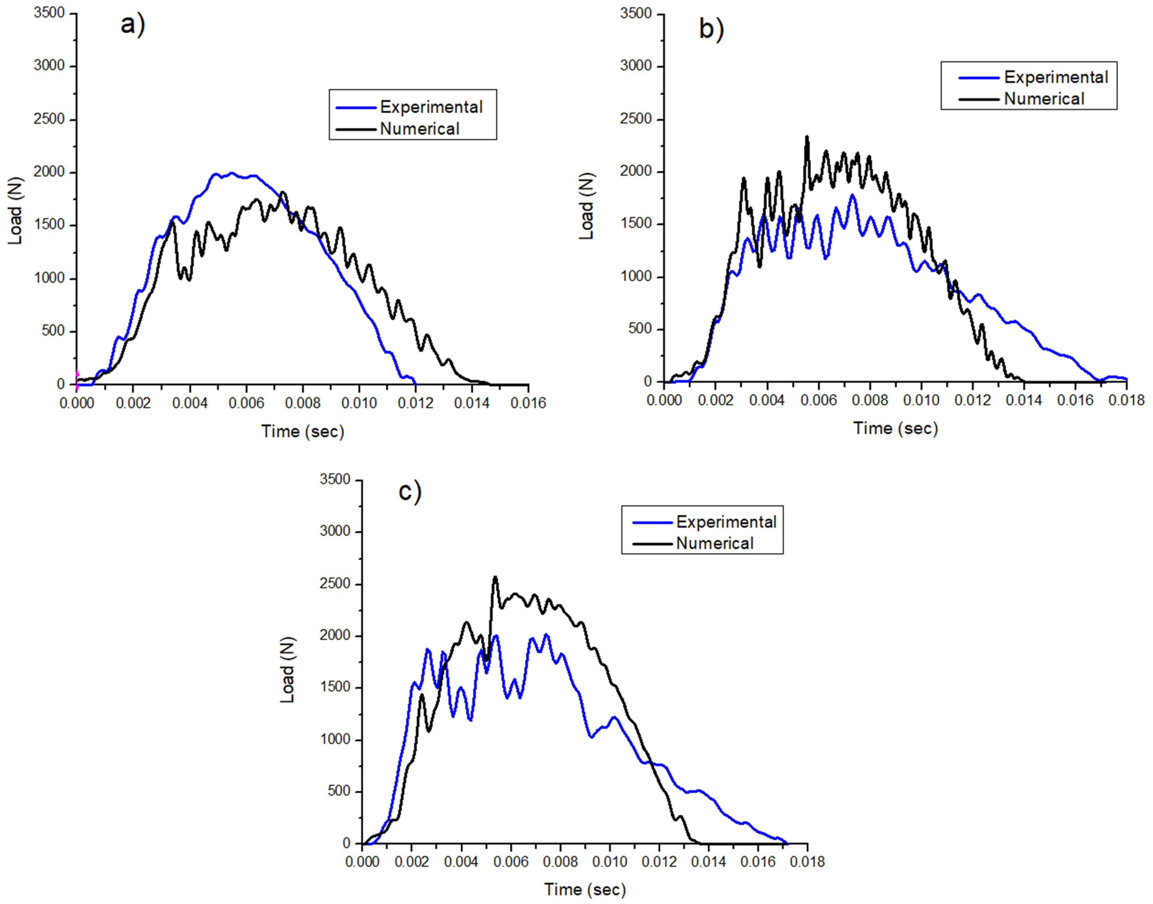
Figure 11(a) shows the comparison of experimental and numerical results at an energy level of 10 J. The impact duration is 0.015 s in the numerical study as compared to 0.012 s in an experimental study. The peak numerical contact force is 1920 N for 10 J impact energy. The difference in contact peak force of numerical and experimental studies in the case of 10 J impact energy is 13.3%. Figure 11(b) shows the comparison of experimental and numerical results at an energy level of 15 J. The impact duration is 0.014 s. The peak numerical contact force is 2650 N for 15 J impact energy. The difference in contact peak force of numerical and experimental studies is 25.1% for 15 J impact energy. Figure 11(c) shows the comparison of the load vs time response of the tested samples at 20 J energy. The impact duration is 0.014 s compared to 0.015 s in an experimental study. The smaller impact duration is observed when specimens are hit with higher impact energy in the present study. Moreover, it is worth noting that a high peak force is produced by higher impact energies. The peak numerical contact force is 3170 J for 20 J impact energy. The difference in contact peak force of the numerical and experimental study is 22.2% for 20 J impact energy.
The difference in impact energies of experimental and numerical studies can be explained by the fact that there is negligible damage in experiments at lower impact energies, while more damage occurs at higher impact energies. Finite element models often involve simplifications and assumptions to make the analysis computationally feasible. These simplifications may not fully capture the complexity of the physical system, leading to discrepancies between the numerical and experimental results. However, experimental tests are subject to various limitations, including measurement errors, calibration issues, and uncertainties in data acquisition. It is crucial to carefully consider the accuracy and precision of the experimental setup and measurements, as they can contribute to differences in the numerical results. Thus, the numerical model does not take into account the effect of damage. Therefore, at low impact energies, the numerical and experimental results are in close comparison. While for higher impact energies, a considerable difference is observed as the numerical model does not take the damage into account. The numerical results show high fluctuations in the contact force. Since the model does not account for damping, therefore these fluctuations exist. Adding a small amount of numerical damping is likely to decrease the fluctuations.
The experimental and numerical results of Bouligand composites show that cracks grow globally through the twisted alignment of fibres and reduce the cracks stress concentration at the impact location. The required force is absorbed as a slow rise of the initial curve, and a high contact duration was observed. The results further suggest that due to the twisted arrangement of fibres in the Bouligand structure, higher deflection is seen under applied load and exhibits a ductile nature. On the other hand, conventional structures showed deep crack concentration at a localised impact location. The orthogonal structure received larger damage and severe cracks in both directions and on the surface of the front and back of the composite laminates. The bias structure showed a highly localised dent at the face and full penetration at the back of the composite laminate. Both numerical and experimental results are in close comparison at low impact energies and suggest that there is negligible damage at lower impact energies. Although in this study, composite laminates were made of a Bouligand structure with 20° twisted angle in layers, which showed improved toughening and ductile nature. Yet, we believe that decreasing the twist angle, for example 1° twisted angle, may improve impact properties significantly.
Conclusion
This study presented a combined experimental and numerical investigation of the low-velocity impact behaviour of Bouligand polymer composite laminates, in comparison with conventional bias and orthogonal fibre architectures. Composite panels were fabricated using vacuum bagging and tested under impact energies of 10, 15, and 20 J. The corresponding load–time histories, contact durations, and damage characteristics were analysed and correlated with finite element simulations.
The results demonstrated that the Bouligand architecture provided superior penetration resistance and damage-tolerant post-peak behaviour compared with the conventional bias and orthogonal laminates. Although the bias structure exhibited a higher maximum load-bearing capacity, its failure mode was more brittle and catastrophic. In contrast, the Bouligand structure showed a gradual load rise, longer contact duration, and delayed catastrophic failure, indicative of improved energy dissipation and progressive damage mechanisms driven by the helicoidal fibre arrangement.
The finite element simulations successfully reproduced the overall load–time response trends observed experimentally, particularly at lower impact energies where material damage was minimal. However, a deviation of approximately 25% was observed at higher impact energies due to the absence of damage and failure criteria in the linear elastic model. These findings underscore the necessity of incorporating progressive damage and failure models in future simulations to enhance prediction accuracy.
In summary, the Bouligand fibre architecture demonstrates strong potential for improving impact tolerance and structural resilience in polymer composite systems. Future work will focus on developing damage-coupled constitutive models and exploring the influence of pitch angle variation on energy absorption, residual strength, and post-impact recovery behaviour to further optimise the design of helicoidal composite structures.
Footnotes
Author Note
Yasir Nawab has left the former organisation, but wants to preserve the former organisation as his primary affiliation University of Kamalia, Rajana Rd, Kamalia, Pakistan

Author’s contribution
Funding
The authors received no financial support for the research, authorship, and/or publication of this article.
Declaration of conflicting interests
The authors declared no potential conflicts of interest with respect to the research, authorship, and/or publication of this article.
Data Availability Statement
The data that support the findings of this study are available from the corresponding author upon reasonable request. The raw experimental and modelling data have not been made publicly available as they form part of ongoing research.