
Abstract
In recent years, the development of adhesive repair in composites has been considered as crucial, as it not only prolongs the service life and fortifies structural resilience but also addresses environmental concerns by restoring and reinforcing composite components across diverse sectors, such as the aeronautic and automotive industries. This study presents a numerical analysis with cohesive zone modelling of adhesively bonded repairs of carbon fibre reinforced polymers with overplies using an epoxy adhesive and provides insights into optimising repairs for such components. The study focuses on two repair geometries: Scarf and Two-Stepped, considering variables such as overlap and reinforcement lengths, and its position when subjected to tensile and three-point bending loading. The results show that the introduction of external reinforcements (overplies) significantly increases the mechanical strength of the repaired joints, resulting in substantial improvements in the failure load for both geometries and both loading conditions. Under tension conditions, the Stepped repair generally obtained better strength than the Scarf geometry. On the other hand, when subject to bending, Scarf repair strength increases considerably in comparison to the Stepped geometry. The failure analysis provides further insights into the failure paths of Scarf and Step repairs.
Introduction
The use of carbon fibre reinforced polymer (CFRP) components for novel aircraft structures has been rapidly increasing over the years, as they prevail over conventional engineering materials due to their high specific strength and stiffness, corrosion resistance, and long fatigue life,1,2 in addition to being extremely lightweight. In fact, the recent Boeing 787 Dreamliner is composed of 50% of composite materials by weight, allowing it to provide the lowest operating costs possible over the life of the aeroplane. However, they also present some weaknesses, such as high sensitivity to temperature and moisture, and vulnerability to impacts, as a result of their quasi-brittle behaviour, which can cause damage by delamination. Thus, it is of extreme importance to consider and develop repair methods for composite structures, both for economic and environmental reasons.
Over the years, bolting repairs have been the current standard for primary bearing load structures, 3 as they are easier to certify. Nonetheless, adhesively bonded joints and repairs have emerged in the last decades as a strong alternative to other conventional joining techniques, such as welding, fastening, and riveting due to their numerous advantages, which include a more uniform stress distribution, reduced weight penalty and minimal aerodynamic disturbance, and possibility of joining dissimilar materials, among others that have been thoroughly discussed in other works.2,4–8 On the other hand, some limitations within this technology make it not fully reliable in critical connections, namely, the lack of development in non-destructive inspection techniques for the detection of weak spots and weak adhesion, as well as uncertainty regarding fatigue and long-term behaviour. 5 As a result, a significant amount of research on adhesive technology and the development of successful adhesively bonded repairs has been carried out in the past few years.
The most popular bonded configurations available are Single-Strap, Double-Strap and Scarf repairs. The first two arrangements are often referred to as temporary repairs, constituting a solution that is intended to provide a short-term fix or to facilitate temporary use of a structure or component, allowing for continued functionality until a more permanent solution can be implemented. The Single-Strap configuration is the easiest to perform; nonetheless, it presents some difficulties, particularly a load eccentricity that greatly affects the peel stresses and strength of the overall repair. The Scarf geometry (Figure 1(a)), a permanent solution, has been shown to eliminate this problem since it does not cause a substantial bending of the components,
1
and allows the reduction of stress concentrations at the bond edges due to the adherend tapering effect.
4
This, in combination with the larger bond areas, makes Scarf repairs extremely efficient and suitable for critical applications, being implemented in high responsibility structures requiring a significant strength recovery and in flush surfaces – which is the case where the Scarf repair and the damaged structure form a single smooth surface – when aerodynamics is an important factor. Schematic representation of the geometries, loading conditions, and reinforcements.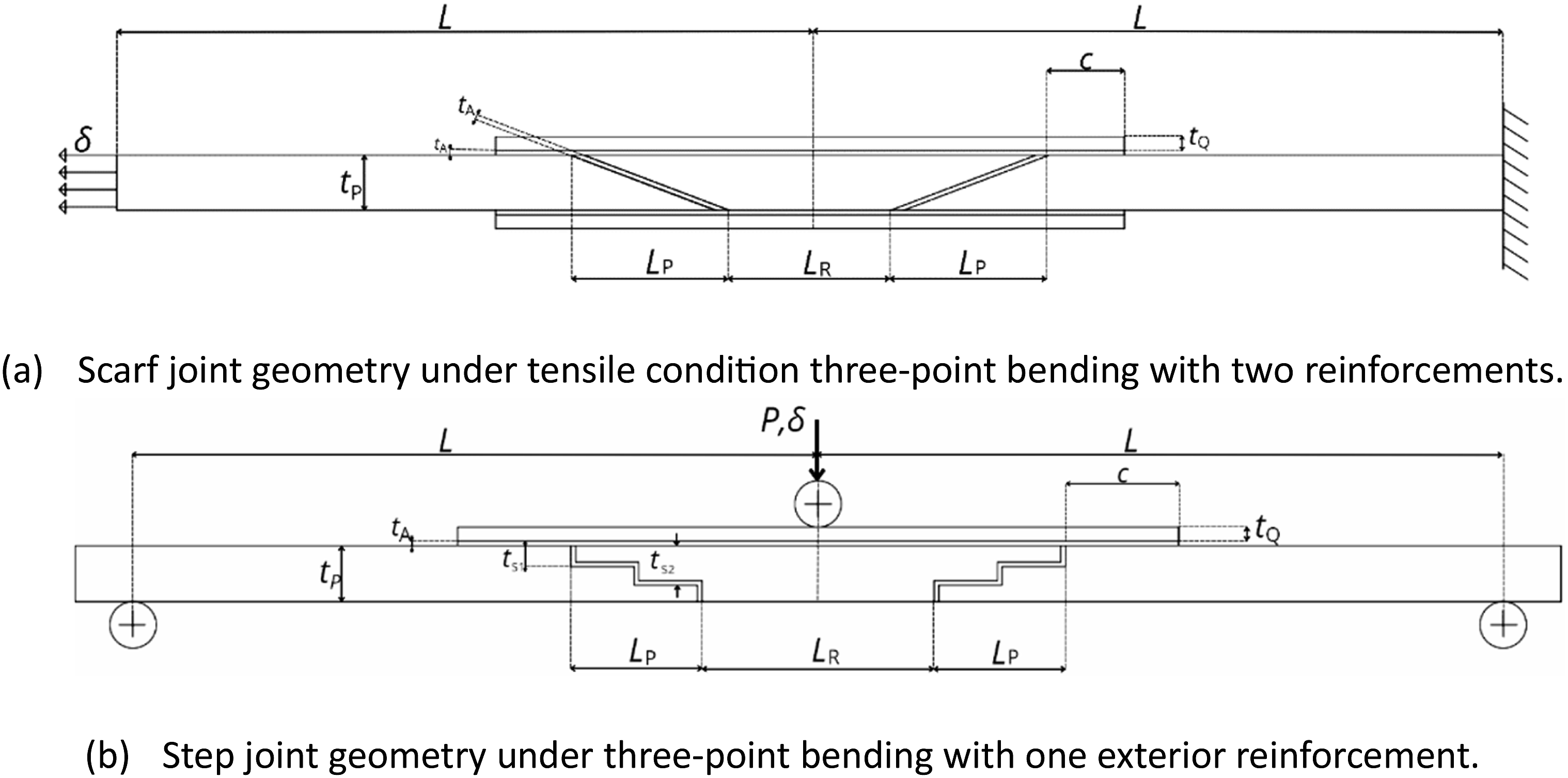
A conclusion that is frequently drawn from studies on Scarf repairs, particularly in tension, is that the strength of the assembly increases exponentially with the reduction of the Scarf angle, α, which comes as a result of the increase in bonding area.1,2,4,7,8 Still, this may not be feasible, considering that smaller Scarf angles would require a larger repair area, and in the particular case of aircraft this repair space may be reduced due to the presence of other structural elements, such as frames or stiffeners. 3 Another downside of Scarf repairs is that they may be difficult to produce, leading to higher costs.
Another configuration that can be presented as a viable option are Stepped repairs (Figure 1(b)), as they are able to sustain great loads due to their design: through the existence of multiple stress concentration zones, there is a relief of stress concentration at the overlap ends, leading to a gradual load transfer from Step to Step. 6 Although they are easier to perform in composites as a result of layered manufacturing techniques, when directly compared to Scarf repairs, researchers have found that multi-Step repairs exhibit a higher stress concentration at the Step corners than Scarf repairs of the same length, 9 implying that they may not be as efficient. Nevertheless, by carefully selecting the right design parameters to lower the peak stresses, Stepped repairs are still able to compete with Scarf repairs, as was demonstrated in the work of Bendemra et al. 10
Considering these benefits, Scarf and Stepped repairs are the preferred configurations for aeronautical applications, and in order to obtain the best performance possible, the design optimisation of these repairs is of great interest. Design parameters of composite bonded joints that are frequently analysed in the literature include the adhesive thickness, Scarf angle or Step ratio, stacking sequence, and ply thickness. Another relevant option that has been evaluated in the last few years has been the addition of overplies over the flush repair. The use of external reinforcements adhesively bonded to the repaired region allows the protection of the weaker regions of the bond, namely, the patch tips, providing a larger cross-sectional area1,4 that strengthens the repair. For the most promising results, these reinforcements should be applied to both the outer and inner surfaces of the structure; however, the application to the inner surface may be impeded by access restrictions.
Gunnion and Herszberg 11 investigated the effect of a composite reinforcement that covered the full length of both faces of a Scarf joint, assessing the variation of the overlaminate thickness (16 and 32 plies) and stacking sequence. With this technique, they achieved a significant reduction in peak peel and shear stresses; however, neither the different lay-ups nor the increasing number of plies provided a noticeable difference. The same conclusion was reached by Breitzman et al., 12 who only applied the overplies on the top surface. Moreira and Campilho 4 performed a parametric study on different configurations of external reinforcements for aluminium adherends in a Scarf configuration, analysing both the placement (on the outer surface only or on both surfaces) and length of the reinforcements (5 mm and 10 mm). The highest strength achieved corresponded to the geometry containing external doublers on both sides of the repair, with a reinforcement length of 10 mm. Through their work, it is possible to deduce that both of these parameters are relevant for the study of overplies.
Due to the numerous material and geometric factors that affect the repairs’ performance, designing the ideal Scarf or Stepped repair for a particular application can be challenging, particularly for composite constructions. Finding accurate design tools for predicting the joints’ behaviour is therefore necessary. Strength prediction of adhesive joints or repairs can be achieved either through analytical models or numerical approaches based on the finite element method (FEM). Analytical models, such as the ones presented by Volkersen 13 and Hart-Smith, 14 often involve closed-form solutions derived from mathematical formulations, allowing for quick estimations of joint strength through the implementation of a failure criterion. However, they are associated with some limitations, being restricted to displacement and stress analyses that may not account for all the loading conditions the structure is subjected to nor capture the stress gradients along the adhesive thickness. Consequently, very few works address composite substrates, which do not take differently oriented plies into consideration. In this sense, numerical analysis using FEM was found to be essential for the study of bonded joints with composite adherends, bringing a new level of understanding of these structures. 8 It allows the estimation of complex stress fields within the adhesive layers, in addition to accurately predicting the failure of the repair and identifying damage onset locations. This type of numerical methodology alone, however, cannot account for the progressive damage evolution and identify failure paths, which is why it is important to also implement cohesive zone models (CZMs). The reason why these aspects are relevant for adhesively bonded joints is related to the significant difference that may exist between damage initiation and failure loads, which comes as a result of the shear and peel peak stresses that develop at the bond edges and are significantly higher than the stresses along the adhesive bond. 1
This work consists of a numerical analysis on the tensile and bending behaviour of 2D Scarf and Two-Stepped repairs of CFRP structures with external reinforcements, using a ductile epoxy adhesive, the Araldite® 2015. The goal is to perform a parametric study to assess the influence of the overlap length and different configurations of the external reinforcements, by varying the reinforcement length and the location where it is applied (either on both surfaces of the repair or only on the outer surface). A comparison between the performance of Scarf repairs and Stepped repairs will also be drawn. The numerical analysis was conducted using the ABAQUS® software, and a triangular CZM law was implemented to simulate the damage evolution.
Methodology and modelling
Geometry
Specimen dimensions for the Stepped and Scarf [mm].
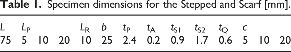
The reinforcements, with a thickness of 0.6 mm, and adhesive, with a thickness of 0.2 mm, mirror the characteristics of other joints. The length of the reinforcement is defined by the length of the c value which can be 5, 10, and 20 mm. Reinforcements with three different lengths (c) may be applied on both sides, solely on the superior side or there can be no reinforcements. This results in seven different geometric configurations to be studied for each of the three overlap lengths, in each of the two types of joints. Ultimately, both repair geometries are analysed in both tensile and three-point bending as seen in Figure 1. Consequently, the study encompasses a comprehensive total of 84 distinct geometric and loading configurations slated for simulation.
Cohesive zone model
To simulate the progressive damage evolution in the adhesive layer, a CZM model was implemented into the FEM analysis. This methodology is capable of computing the total response of structures up to the final rupture, and it is based on the definition of a pre-defined crack path.
15
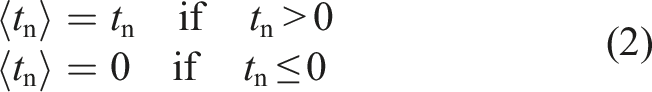
Simulation of the macroscopic damage occurs by establishing a relationship, known as the traction-separation law, between the stresses/cohesive tractions and relative displacements (in tension or shear) that connect homologous nodes of the cohesive elements
16
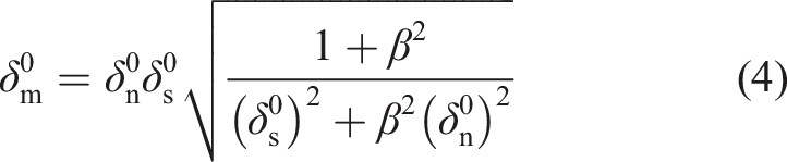
within the crack path. Under pure mode loading, the constitutive relationship corresponds to an elastic behaviour up to a maximum value, that is, the cohesive strength in tension ( Traction-separation law with linear softening law available in ABAQUS®. Adapted from Ref. 4.
The areas under the traction-separation laws in pure mode loading (tension and shear) are equivalent to the corresponding fracture toughness, 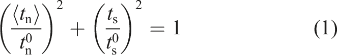

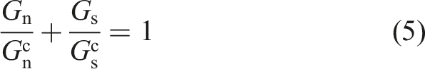
The strain energy release rate in each mode at complete failure is obtained from,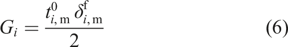
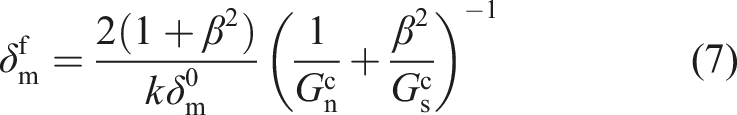

Following this procedure based on equivalent relative displacements, it is possible to simulate damage propagation under mixed-mode I + II with varying mode ratio during loading history.
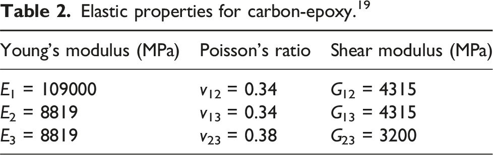
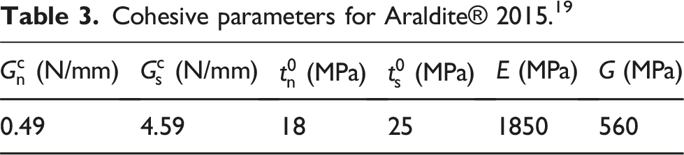
Material Proprieties
Finite element model
The numerical analysis was performed resorting to the FEM software ABAQUS®. For the simulations, two-dimensional models were considered, using the assumption of plane strain as the out-of-plane width of 25 mm was deemed sufficiently large relative to adherends thickness. The simpler two-dimensional analysis of Scarf and Step joint geometries avoids the complexity of a real patch of finite width and complex load transfer and enables comparative studies to be carried out in relation to certain geometric parameters. The elements used for the adherend regions were therefore mainly CPE4R, that is, 4-node bilinear plane strain quadrilaterals, with reduced integration and hourglass control. In some regions of the Scarf models, CPE3, that is, 3-node linear plane strain triangles, was used, for geometry transitions. For the adhesive layers, COH2D4, 4-node two-dimensional cohesive elements, was used, with 0.2 mm of element thickness, as this is the thickness of the adhesive layers. A mesh convergence analysis was previously carried out by the research group, 20 and it was shown that the 0.2 × 0.2 mm2 element size of the adhesive layer gave rise to accurate results.
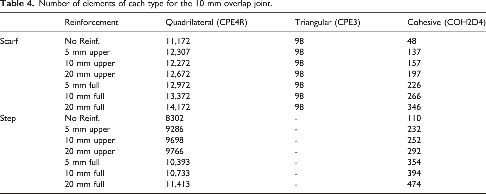
The mesh was refined locally in the regions of interest, such as the tops of the geometry or at geometry transitions, as seen in Figure 3, where the meshes for the configurations without reinforcements and with full reinforcements on both sides, for both Scarf and Step repairs, are shown, with the objective of improving computational efficiency and so that stress concentrations were better captured. Both the mesh and the pseudo-time increments were sufficiently refined. Again, with the objective of reducing computational costs, only half of the specimens were used, and to achieve this a symmetry condition was applied. The number of elements is presented in Table 4 for the case of the 10 mm overlap joints. The 5 mm and 20 mm overlap joints will have, respectively, more and less elements, for geometric reasons, mainly because of the size of the reinforcements, but in general the element size did not vary significantly from one case to another. Details of the mesh for different configurations. Represented in blue are the cohesive elements. Number of elements of each type for the 10 mm overlap joint.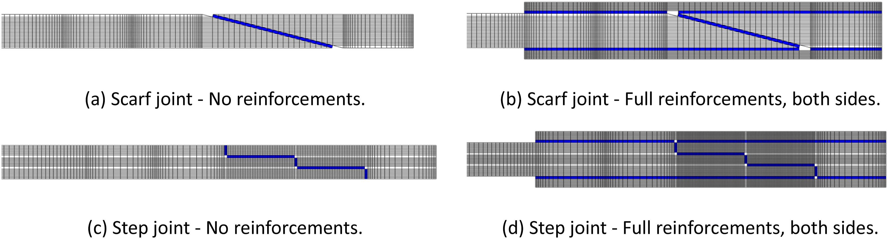
As mentioned, two types of loading conditions will be applied to all of the geometric configurations: uniaxial tension and three-point bending. Tension conditions were implemented in ABAQUS® by restricting vertical movement and imposing a displacement on the left side of the specimen in the horizontal direction (2 mm, which is sufficiently large to cause failure). Symmetry conditions on the horizontal direction were considered on the right side, since only half of the specimen is being simulated.
The three-point bending condition was performed by restricting vertical movement on the left side of the half specimen and by imposing a vertical displacement (20 mm, which is sufficiently large to cause failure) on the right side. Once again, a symmetry condition on the horizontal direction was applied.
The 42 geometric configurations combined with these two loading conditions resulted in a total of 84 simulations performed, as previously mentioned.
It should be noted that the numerical methodology followed in this work was previously validated by the research group on the basis of experimental results for the Scarf21,22 and Step20,22 geometries.
Results
This section presents the results obtained from the numerical analysis, in which the stress distribution of the adhesive layer, the strength of the various repair configurations and the resulting failure paths were evaluated in order to assess the influence of the repair geometry on its performance.
Stress analysis
The numerical models were updated in order to obtain the stress profiles within the adhesive layer. With this aim, the layer of cohesive elements representing the adhesive was replaced by solid elements (CPE4R). In this context, 10 solid elements were implemented trough the thickness of the adhesive layer to capture well the stress profiles at its mid-thickness. The stress profiles were only obtained for the configurations with an overlap length of 10 mm and for the adhesive layer of the patch repair (overlap length layer). The peel (σy) and shear (τxy) stress distributions for each loading case – tension (Section 3.1.1) and bending (Section 3.1.2) – are presented and analysed. The stress profiles were normalised by the shear average stress (τavg) of each corresponding geometry baseline, that is, by the no reinforced (No Reinf.) case.
Tensile load
Figures 4a and 4(b) show the distribution of peel (σy) and shear (τxy) stress, respectively, along the adhesive layer of the repair patch for the case of the Scarf repair under tensile load. For the No Reinf. case, it is possible to observe peak stresses located at the edges (locations 0 and 1) of the repair patch adhesive layer. With the inclusion of the upper reinforcement, the peak stresses are minimised in that region (location 0), but in opposite edge (with no reinforcement and location 1), it is possible to observe an increase of those peak stresses, which is more evident for the τxy stress (Figure 4(b)). When including both reinforcements (full case), it is observed a reduction of the peak stresses at both locations 0 and 1, and also a more uniform distribution of the σy and τxy stresses. The locations of the peak stress are zones that are likely to give rise to the onset of damage that will lead to failure of the adhesive layer. These aspects will be discussed in more detail in section 3.3. σy (a) and τxy (b) stress distribution for the Scarf repair under tensile load.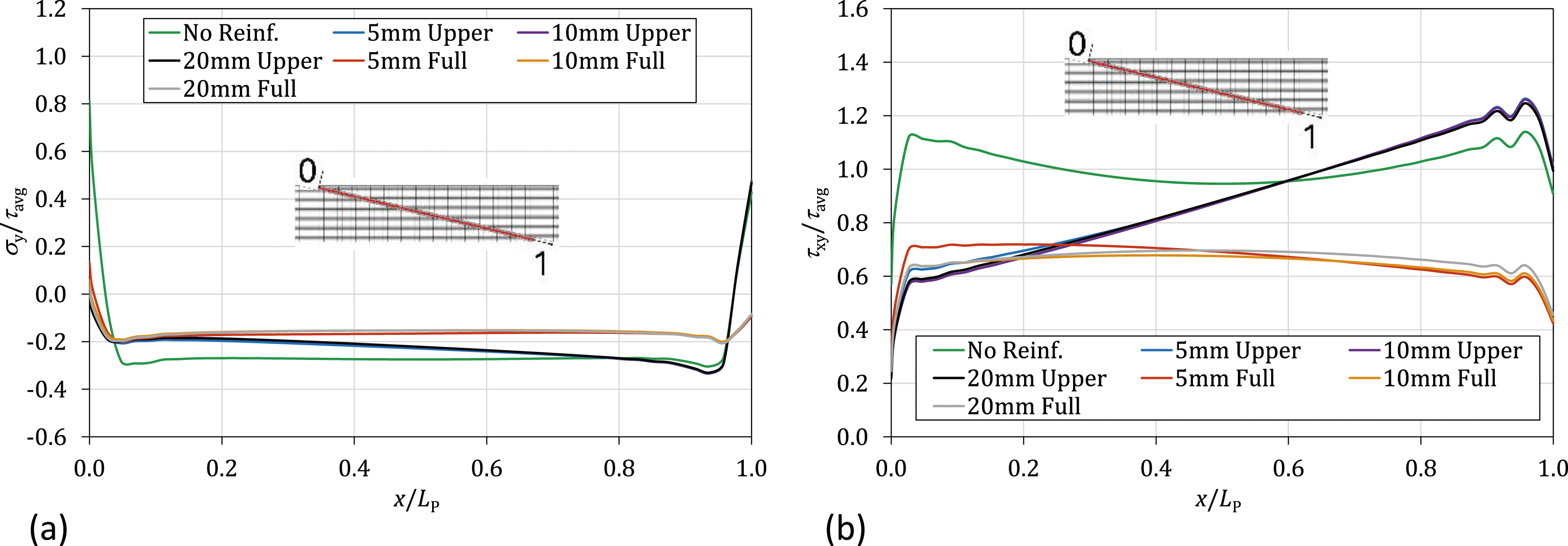
With regard to the Step repair, the distribution of stresses σy and τxy is shown in Figures 5a and 5(b), respectively. For this particular geometry, additional stress peaks are observed in the transition between steps (location 0.5). Bearing this in mind, the main conclusions that were drawn for the Scarf geometry can also be recognised for the Step repair geometry. σy (a) and τxy (b) stress distribution for the Step repair under tensile load.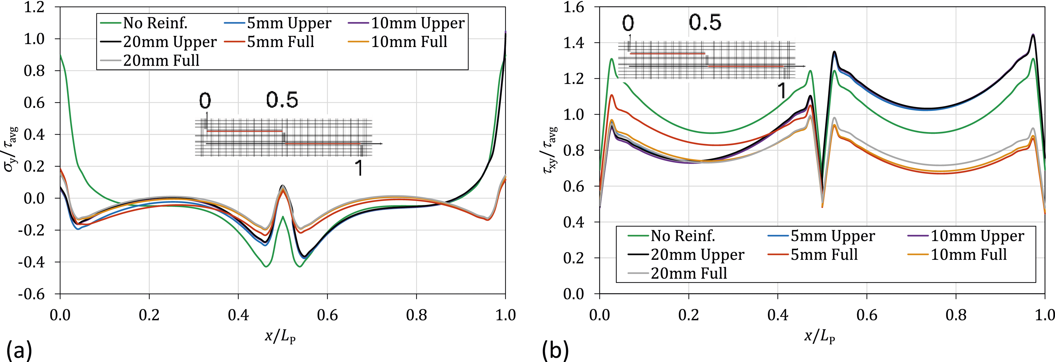
Bending load
Regarding the bending load, the distribution of σy and τxy for the Scarf repair is presented in Figures 6a and 6(b), respectively. In general, peak normal and shear stresses occur close to the overlap extremities. Comparing the No Reinf. type with the upper reinforcement configuration, the peak stresses decrease at location 0, while at location 1 they increase. When adding both reinforcements (Full case), it is possible to visualise a more uniform stress distribution along the adhesive layer and also a reduction of the peak stress at both location 0 and 1. σy (a) and τxy (b) stress distribution for the Scarf repair under bending load.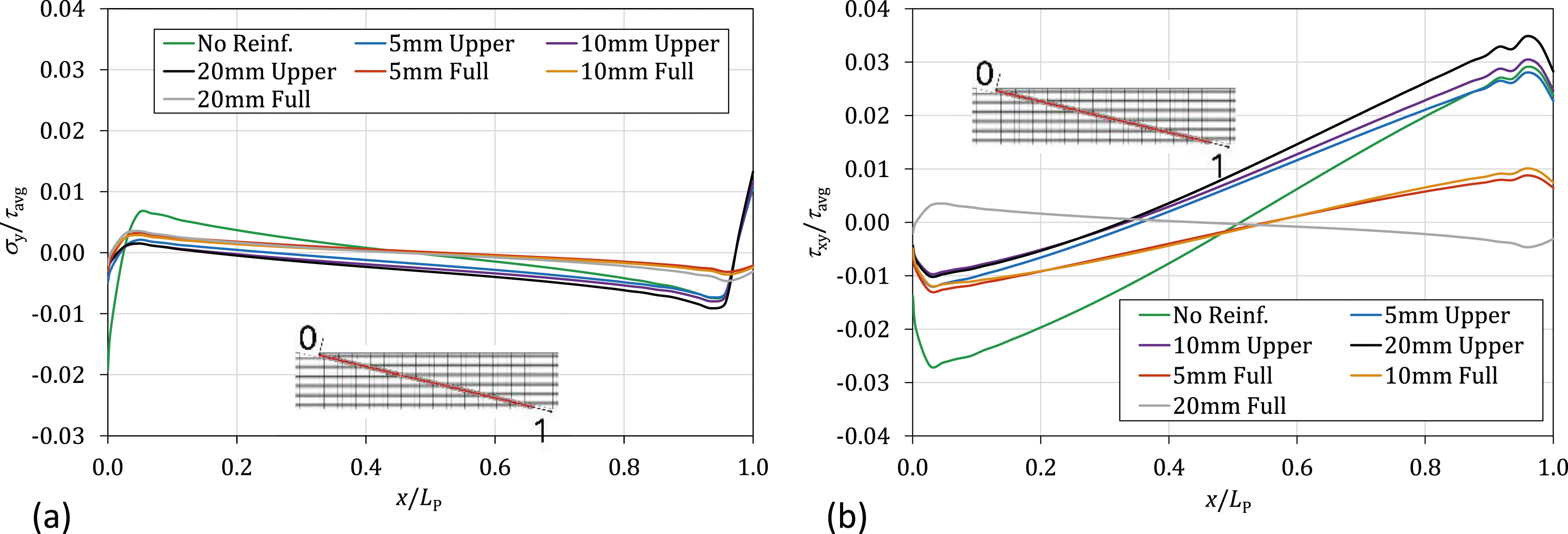
Figure 7(a) shows the σy distribution, while Figure 7(b) presents the τxy distribution for the Step repair geometry. As mentioned above, due to the geometry of this repair, there is an additional stress peak at location 0.5 (transition between Steps). Furthermore, with regard to the profiles of both stress distributions, the conclusions drawn from the previous case (bending load of the Scarf) are the same. σy (a) and τxy (b) stress distribution for the Step repair under bending load.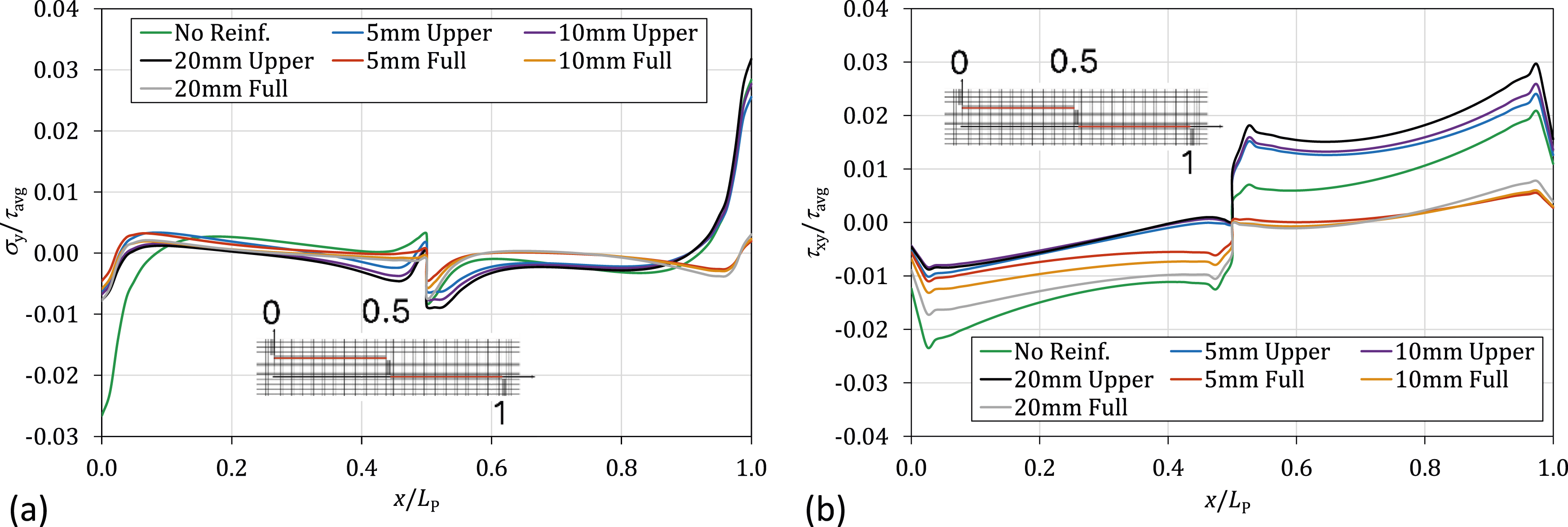
Strength analysis
For the strength analysis, the load–displacement (P-δ) curves for all considered cases were extracted. For each loading case – tension (Section 3.2.1) and bending (Section 3.2.2) – the effects of the reinforcement geometry and the overlap length of the joint will both be considered, for the Scarf and Step configurations.
Tensile load
Starting by assessing the influence of the reinforcement geometry, the models with an overlap length of 10 mm were used to establish the comparison. Figure 8 showcases the resulting P-δ curves for the Scarf and Step repairs under tension, taking into consideration the symmetry of the FE model, meaning that the obtained displacements were doubled. Load–displacement curves obtained for the 10 mm overlap joints under tensile load.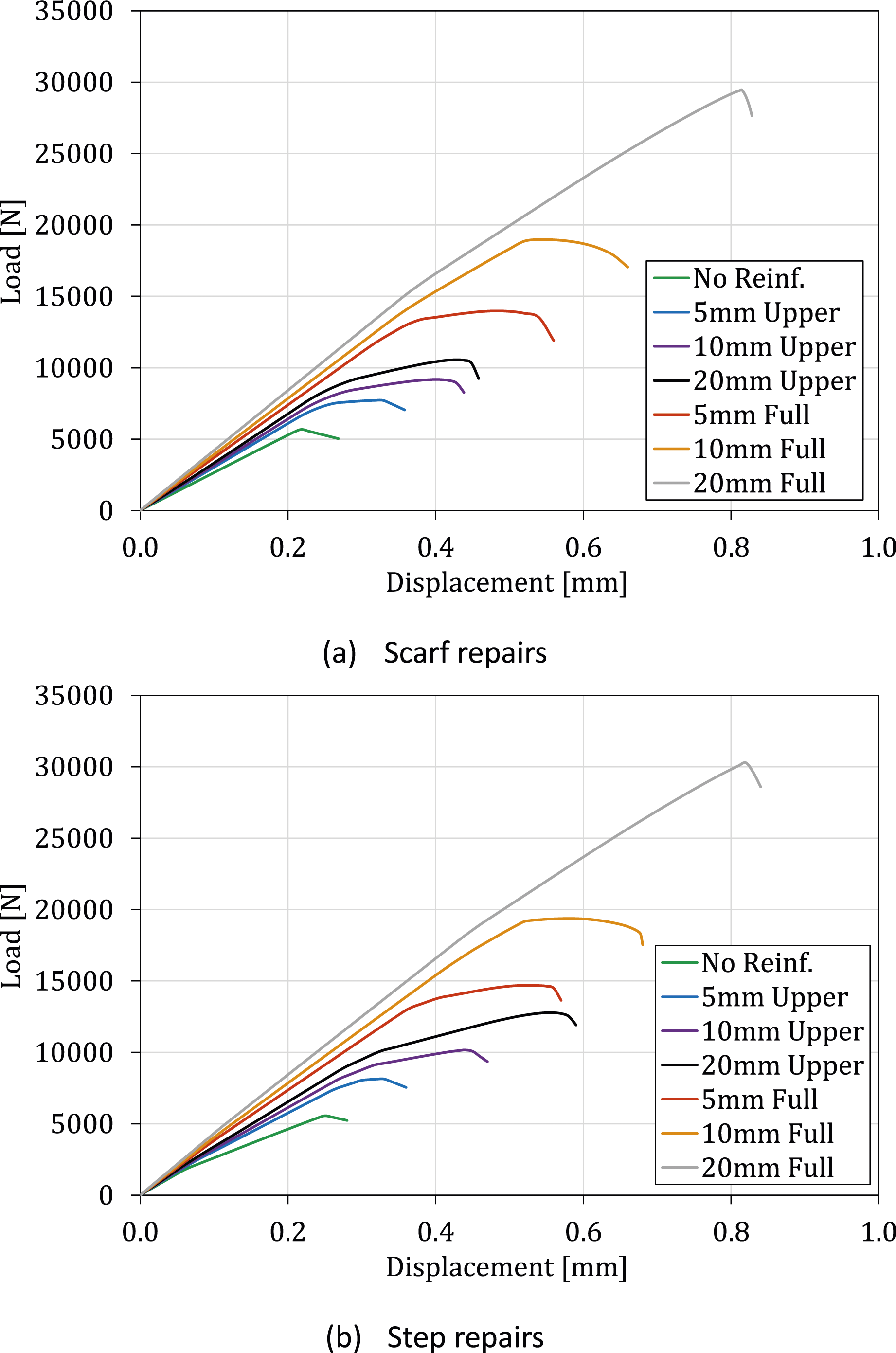
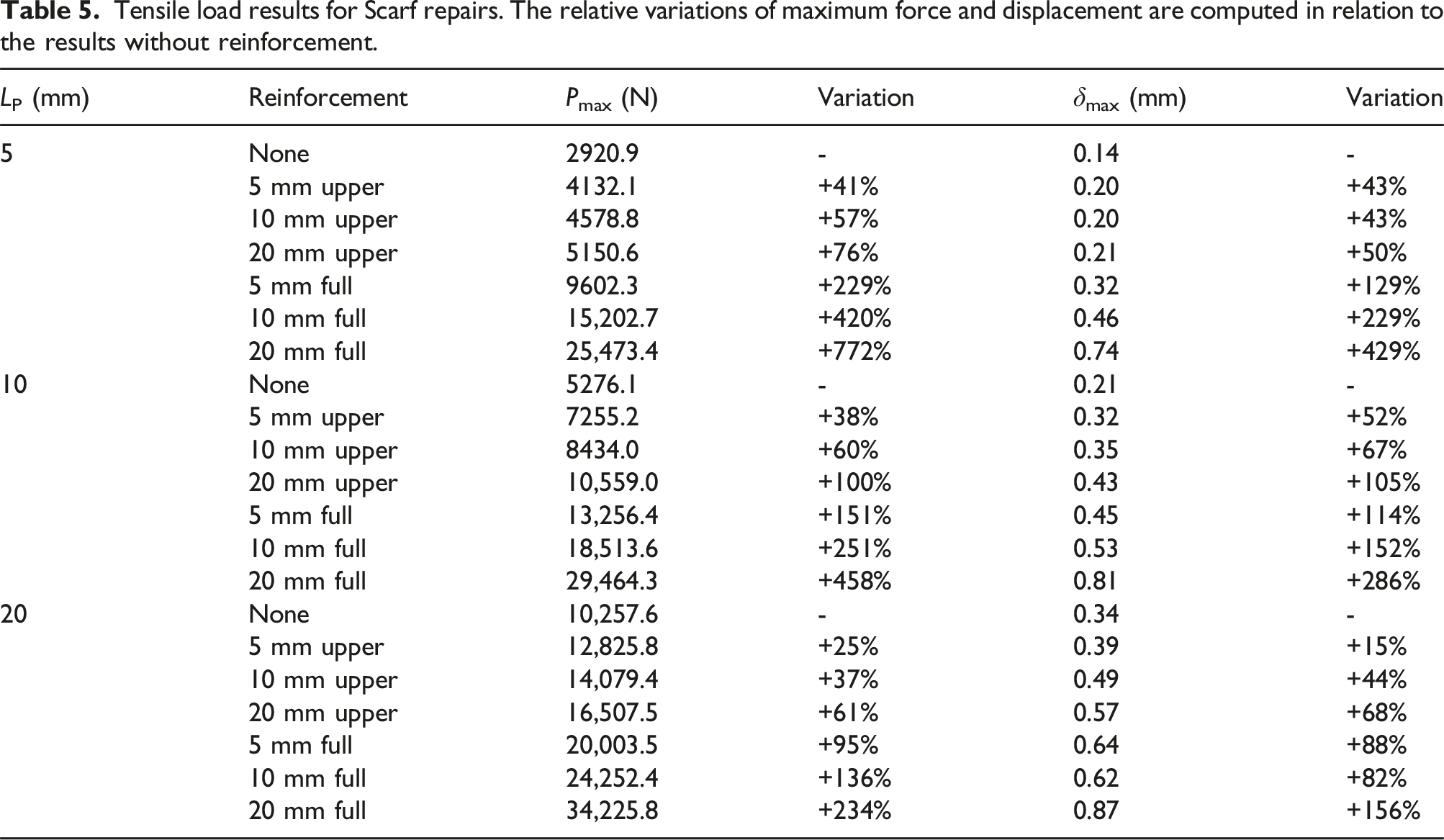
For the Scarf repairs, the reference geometry, that is, with no reinforcements, failed at 5276.1 N for a displacement of 0.21 mm, corresponding to the lowest stiffness achieved. It is possible to see that the introduction of a reinforcement, regardless of its configuration, brought visible improvements to the strength of the joint – the upper 5 mm reinforcement increased the maximum load by 38%, with other reinforcements bringing about even greater strength enhancements. The increase of the reinforcement length up to 20 mm leads to a gain of 100% relative to No Reinf. case, which reflects an interesting result. The benefits of applying reinforcements on both sides of the surface translate are even more relevant. In fact, the increase of strength is in the range of 151%–458% for reinforcement lengths of 5 mm–20 mm. This is in line with the results found in literature, as it has been shown that the addition of reinforcements to both sides of the repair resulted in a reduction of peak peel (σy) and shear (τxy) stresses at both Scarf ends, 4 providing a more significant strength improvement, while having only the outer surface reinforced could result in an earlier failure at the inner Scarf edge.
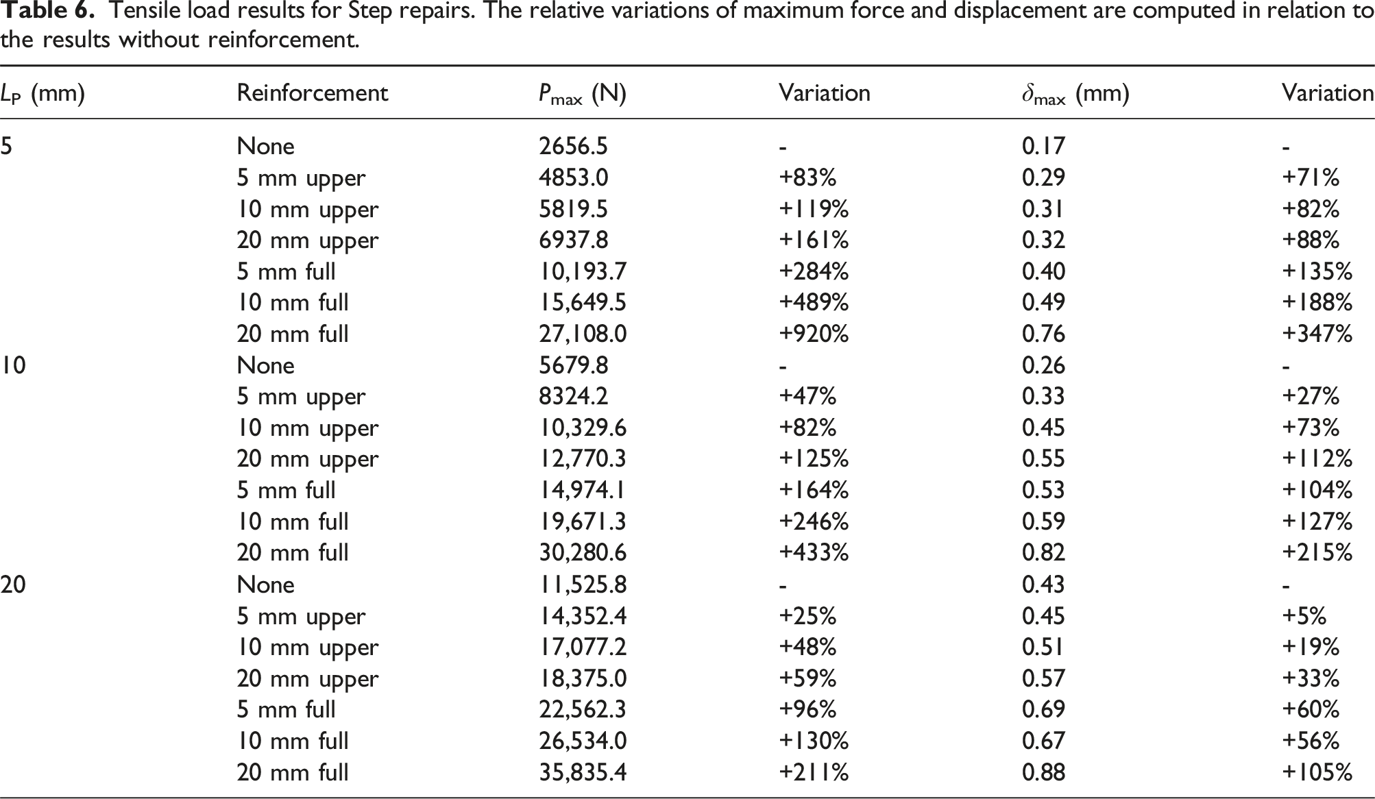
A very similar analysis can be made for the Step geometry regarding the effects of the reinforcement configurations. In general, the gains are slightly higher compared with Scarf repairs except for the 10 and 20 mm full cases.
Overall, the stiffness of the Scarf and Step repairs appears to be similar. Furthermore, although there was no considerable difference, under tension, the Step geometry was able to withstand higher loads than the Scarf geometry, in addition to failing at larger displacement values. This difference is not as noticeable when considering the unreinforced cases. However, the Step repair seems to greatly benefit from the reinforcements. As was mentioned earlier, one of the issues associated with Stepped repairs was that they could exhibit a higher stress concentration at the joint corners than Scarf repairs of the same length, and the addition of the overplies allows to overcome this issue. As a result, the benefit of a larger bonding area offered by Step repairs becomes more noticeable, providing a longer pathway for crack propagation, thus requiring more energy to initiate and propagate a failure compared to a Scarf joint. This increased energy absorption eventually could result in a higher displacement at failure. Other reasons could include a smoother stress transfer, resulting in better load distribution and higher load-carrying capacity under tension, as well as enhanced shear strength.
To consider the effect of the overlap length on the strength of the bonded repair, the curves of Figure 9 were plotted, indicating the Pmax value of every configuration under tension for the three different overlap lengths: 5 mm, 10 mm, and 20 mm. Maximum load for each overlap length and reinforcement case, in tension.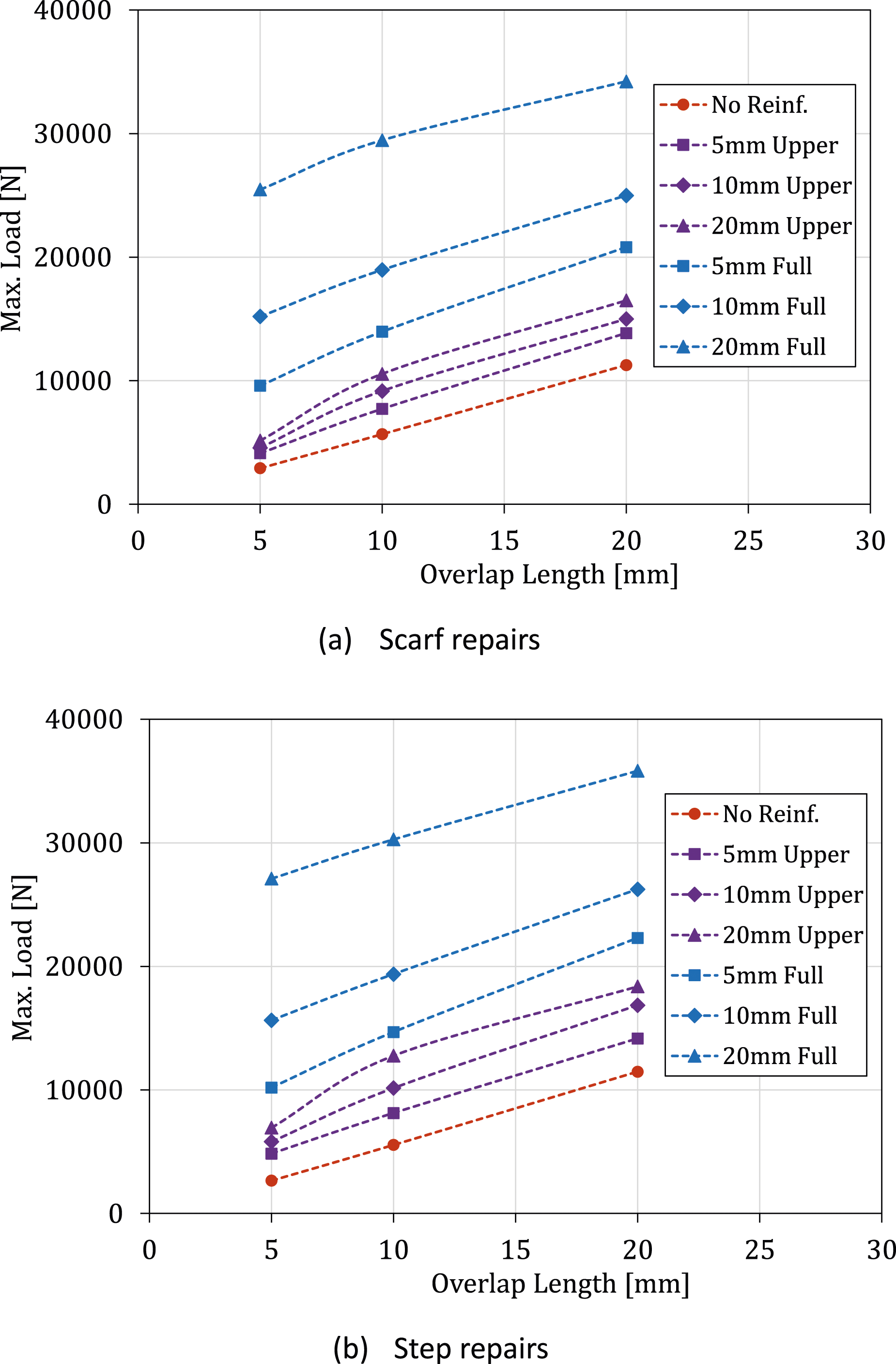
For the Scarf joint, this effect of overlap length variation translates into a variation of the Scarf angle α, as increasing overlap values will result in a smaller angle. This explains the increase of Pmax with the increasing value of LP, with multiple studies showing that the strength of Scarf repairs increases with the decrease of α. This is due to the increase in bonding area, which contributes to a stronger bond, more efficient load transfer, greater shear strength, and reduced peeling tendency. In the case of the Step joint, there is a more linear variation in the maximum force with the length of the overlap, also related to the larger bonding area. That said, longer overlap lengths seem to be particularly beneficial for Scarf repairs, under tension.
Tensile load results for Scarf repairs. The relative variations of maximum force and displacement are computed in relation to the results without reinforcement.
Tensile load results for Step repairs. The relative variations of maximum force and displacement are computed in relation to the results without reinforcement.
Bending load
Regarding the bending load case, the impact of the reinforcement geometry on the results is going to be assessed first, using the models with 10 mm of overlap length. The P-δ curves for these models under the bending load case are shown in Figure 10. For model symmetry reasons, the force collected from the FE simulations was duplicated. Load–displacement curves obtained for the 10 mm overlap joints under bending load.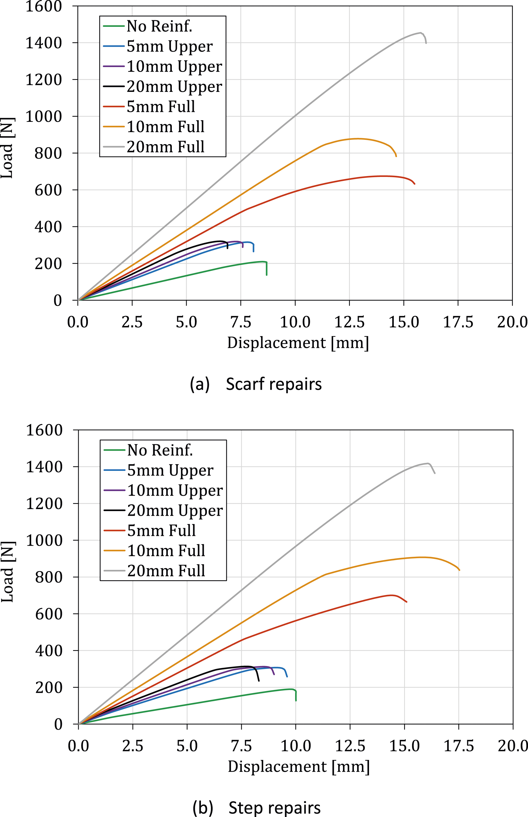
Starting with the geometry with no reinforcements, the Scarf and Step repairs failed at similar loads, of 188 N and 190 N, respectively, although the latter failed at a 29% higher displacement. These are the lowest load values of failure for this loading condition, since, as was observed in the tensile case, every reinforcement configuration showed improvements over the reference geometry. It is worth noting, however, that this is not the case for the displacements, as both Scarf and Step specimens, without reinforcement, fail at higher displacements than with only upper reinforcement, which is more visible in the Step joint.
For the cases where the overply was applied only to the outer surface, an increase in maximum load of 51% for the Scarf joint and 62% for the Step joint were observed for the 5 mm reinforcement. On the other hand, the increase from 5 mm to 20 mm only led to slight improvements in both types of joint. Reinforcing both sides leads to a significantly higher failure load, with the Scarf joint showing an increase ranging between 251% and 672% while the Step joint revealed improvements of 269%–647%, both as function of the reinforcement length. These two reinforcement configurations also experienced much higher displacements at failure than the previous geometries. The great jump in strength between reinforcing one side and reinforcing both sides may be explained by the fact that the critical zone for both joints in this load case is on the underside, and therefore, the full reinforcement has the greater impact, since it affects this zone, while the single reinforcement does not. This is further discussed in Section 3.3.2.
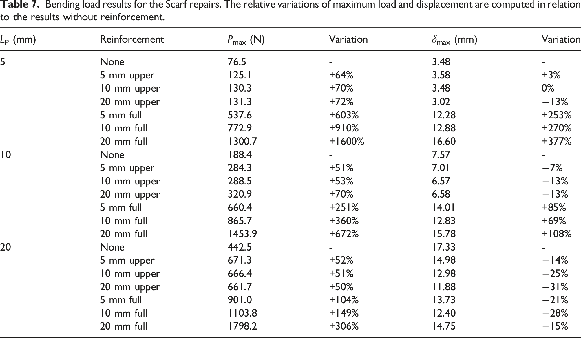
In Figure 11, the failure load for each geometry simulated is presented, as a function of the overlap length. As was the case in the tensile load, it can be observed that an increase in overlap length generally leads to an increase in strength. In the case of Step repairs, this increase is mostly linear, although this seems to not apply to the repair with no reinforcement, which only shows a 38% improvement between the 10 mm and 20 mm overlap, compared to the 142% increase between the 5 mm and 10 mm. This is likely a sign that the Stepped joint is saturated, and subsequent overlap length increases will lead to progressively lower strength enhancements. The value of LP, at which this occurs, depends on various characteristics of the repair and reinforcement. For the Scarf repairs, the increase seems to be linear with an improvement of 578% in failure load for the 20 mm overlap length, which is remarkable. Maximum load for each overlap length and reinforcement case under bending.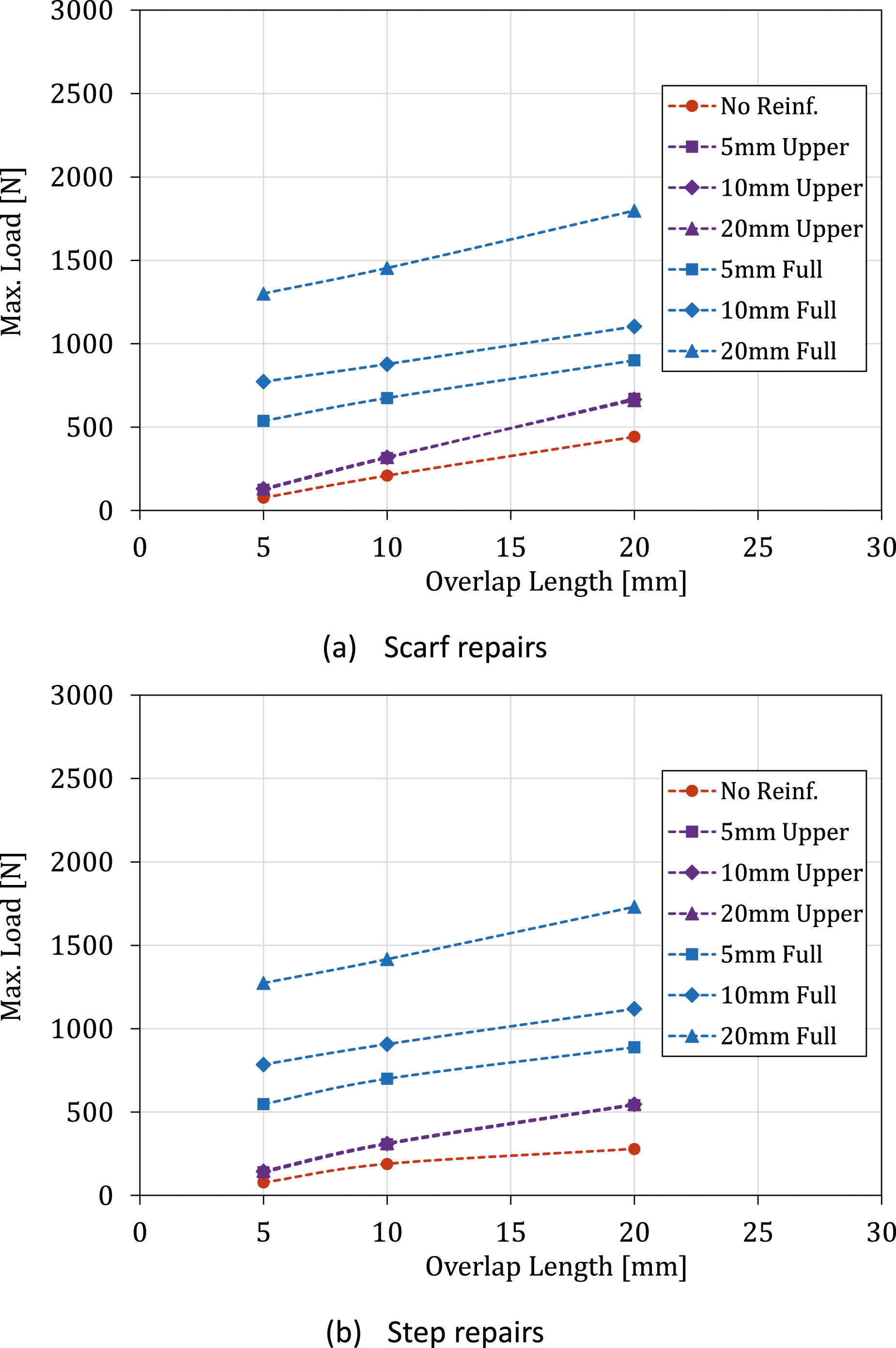
Bending load results for the Scarf repairs. The relative variations of maximum load and displacement are computed in relation to the results without reinforcement.
Bending load results for the Step repairs. The relative variations of maximum force and displacement are computed in relation to the results without reinforcement.
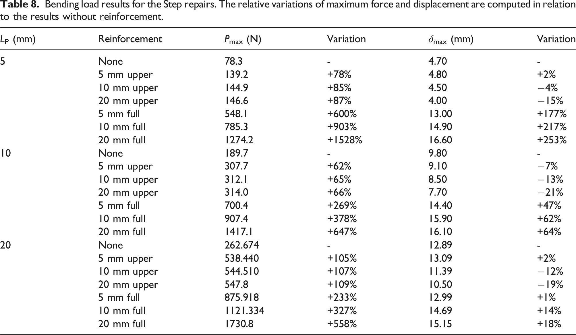
Moreover, it can be seen that, for 10 mm fully reinforced Scarf and Step repairs, the overlap length does not have a significant effect on the maximum displacement, contrarily to what happens for the failure load. Nonetheless, for unreinforced specimens, increasing the overlap length leads to significant increases in the maximum displacement, for both repair types. In fact, in the bending cases, the maximum displacement at failure, 16.40 mm, was recorded for the unreinforced Scarf repair with 20 mm overlap length. This effect was not observed in the tensile load (see Table 5 and Table 6). The reason for the discrepancy in the repairs with the maximum displacements at failure between the tensile and bending cases lies in the different loading conditions applied to the specimens. While in the tensile load, specimens are almost uniformly stretched until failure, and in the bending case, the deformation of the repair is non-uniform, since it is controlled by the bending moment. Consequently, in the second case, the relationship between the loads and displacements at failure is not of linear nature.
Finally, it should be remarked that the increase in strength from the unreinforced and upper-reinforced specimens to the fully reinforced specimens is very significant, due to the previously discussed importance of having an overply in the lower side of the specimen. In the 5 mm overlap Step repairs, the increase in strength from the unreinforced specimen to the 20 mm fully reinforced one was 1528%.
Failure analysis
Recognising how failure initiates are crucial for pinpointing weak points in a joint, enabling precise improvements for overall structural reinforcement. Understanding how reinforcements impact the final strength results is equally important. In this case, it is worth noting that the path to failure does not depend on the overlap in the repaired joint. Therefore, the focus here is on models with a 10 mm overlap, considered as reference points.
The ABAQUS® software was used to calculate the adhesive failure path, employing the SDEG (Stiffness DEGradation) damage parameter. This parameter, analysed along a pre-defined path within the adhesive layer, serves as a scalar measure of stiffness degradation for each element it traverses. The SDEG is a quantitative parameter that takes on the value of 0 in the undamaged state and varies gradually from 0 to 1 after the onset of damage, meaning that the element is in the softening region of the CZ law. The complete failure of the cohesive element is attained when the SDEG reaches a value of 1. 23
Tensile load
In the Scarf joint, when subjected to tensile loads, the absence of reinforcement translates into a damage initiation at the ends of the overlap, as can be seen in Figure 12(a). This is to be expected due to the inevitable stress concentration in this region. However, as a result of the benefit of using a Scarf configuration, the damage propagates fairly even throughout the bondline. Introducing reinforcements changes the failure path. In fact, when only upper reinforcement is used (Figure 12(b), Figures 12c and 12(d)), the lower part is exposed to high peel stress, causing it to fail before the rest of the adhesive. Considering upper and lower reinforcements, the upper part tends to fail first due to higher peel stresses for 5 and 10 mm full (Figures 12e and 12(f)). However, for 20 mm full (Figure 12(g)), the extensive reinforcement length clearly alters this tendency, and the adhesive layer of the overlap becomes the critical region. Scarf repair results in tensile load simulations: a) No Reinf.; b) 5 mm upper reinforcement; c) 10 mm upper reinforcement; d) 20 mm upper reinforcement; e) 5 mm full reinforcement; f) 10 mm full reinforcement; and g) 20 mm full reinforcement.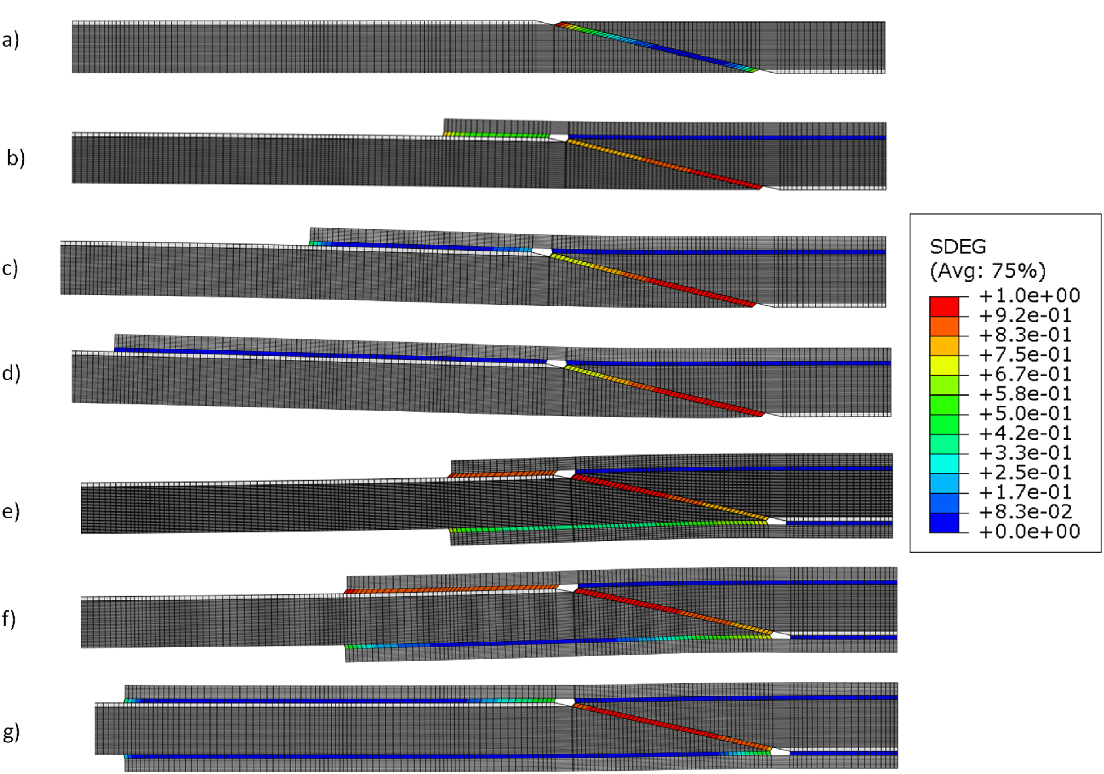
In the Step joint under tensile loads (Figure 13), cases without reinforcements and with two reinforcements have similar failure paths, damaging the joint by peel stresses at the vertical parts of the bonded region. Yet, when only upper reinforcement is applied, the upper part is reinforced, causing the lower part to fail first due to increased peel stress. Step repair results in tensile load simulations: a) No Reinf.; b) 5 mm upper reinforcement; c) 10 mm upper reinforcement; d) 20 mm upper reinforcement; e) 5 mm full reinforcement; f) 10 mm full reinforcement; and g) 20 mm full reinforcement.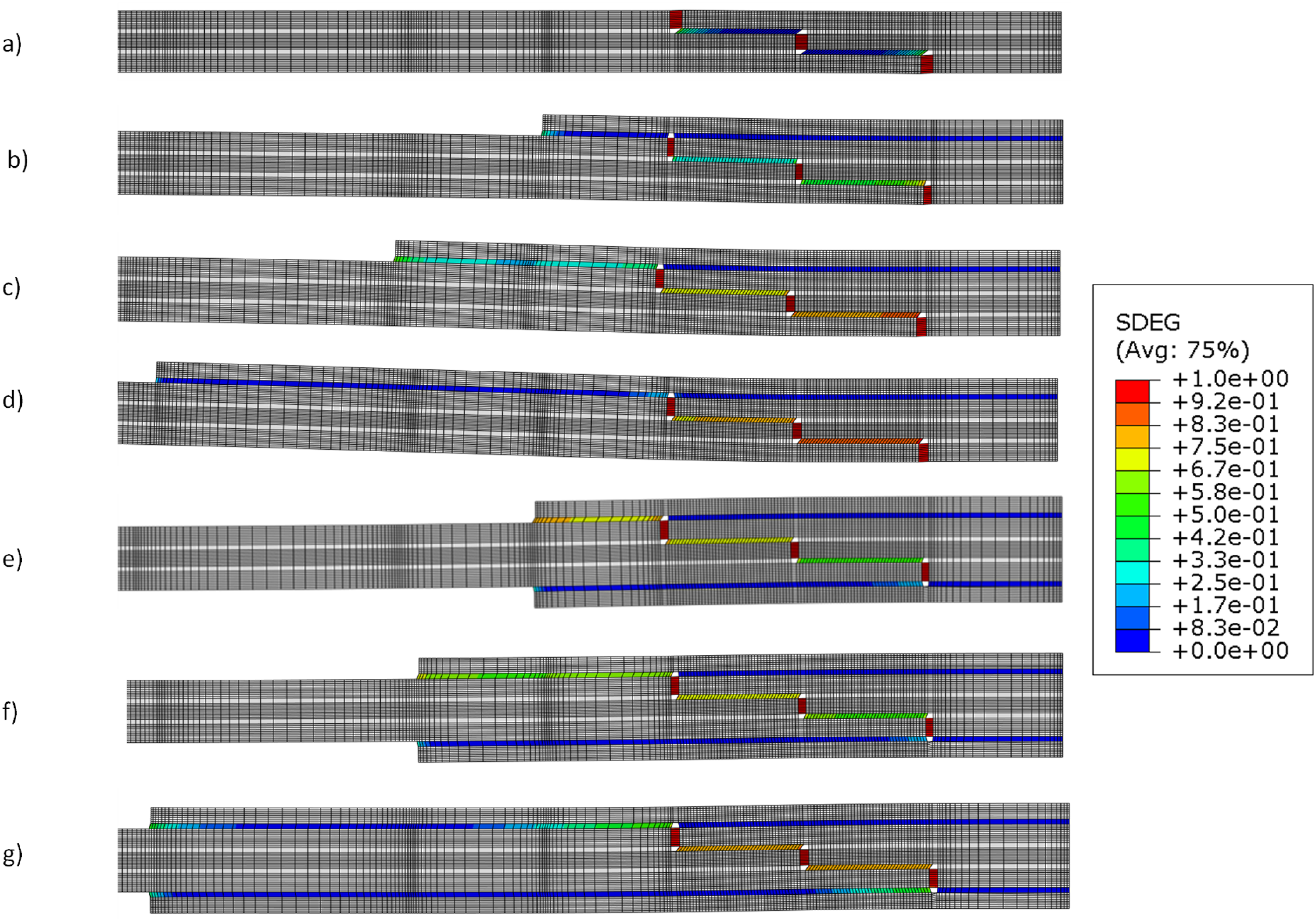
Bending load
In the context of bending scenarios, examining Scarf repairs in Figure 14 reveals distinct behaviours. Without reinforcement (Figure 14(a)), the lower part fails initially due to peel stress, while the upper part shows minimal degradation. In cases with only upper reinforcement (Figure 14(b), Figures 14c and 14(d)), the failure path resembles the unreinforced scenario, as the critical lower part remains largely unchanged. The upper reinforcement shifts the neutral axis upwards, resulting in failure initiation in the lower part due to the higher peel stresses. Introducing two reinforcements (Figure 14(e) and Figures 14f and 14(g)) shifts the failure initiation towards the upper one. This shift is attributed to development of relevant shear stresses in the overlap region of the upper reinforcement. Scarf repair results in bending load simulations: a) No Reinf.; b) 5 mm upper reinforcement; c) 10 mm upper reinforcement; d) 20 mm upper reinforcement; e) 5 mm full reinforcement; f) 10 mm full reinforcement; and g) 20 mm full reinforcement.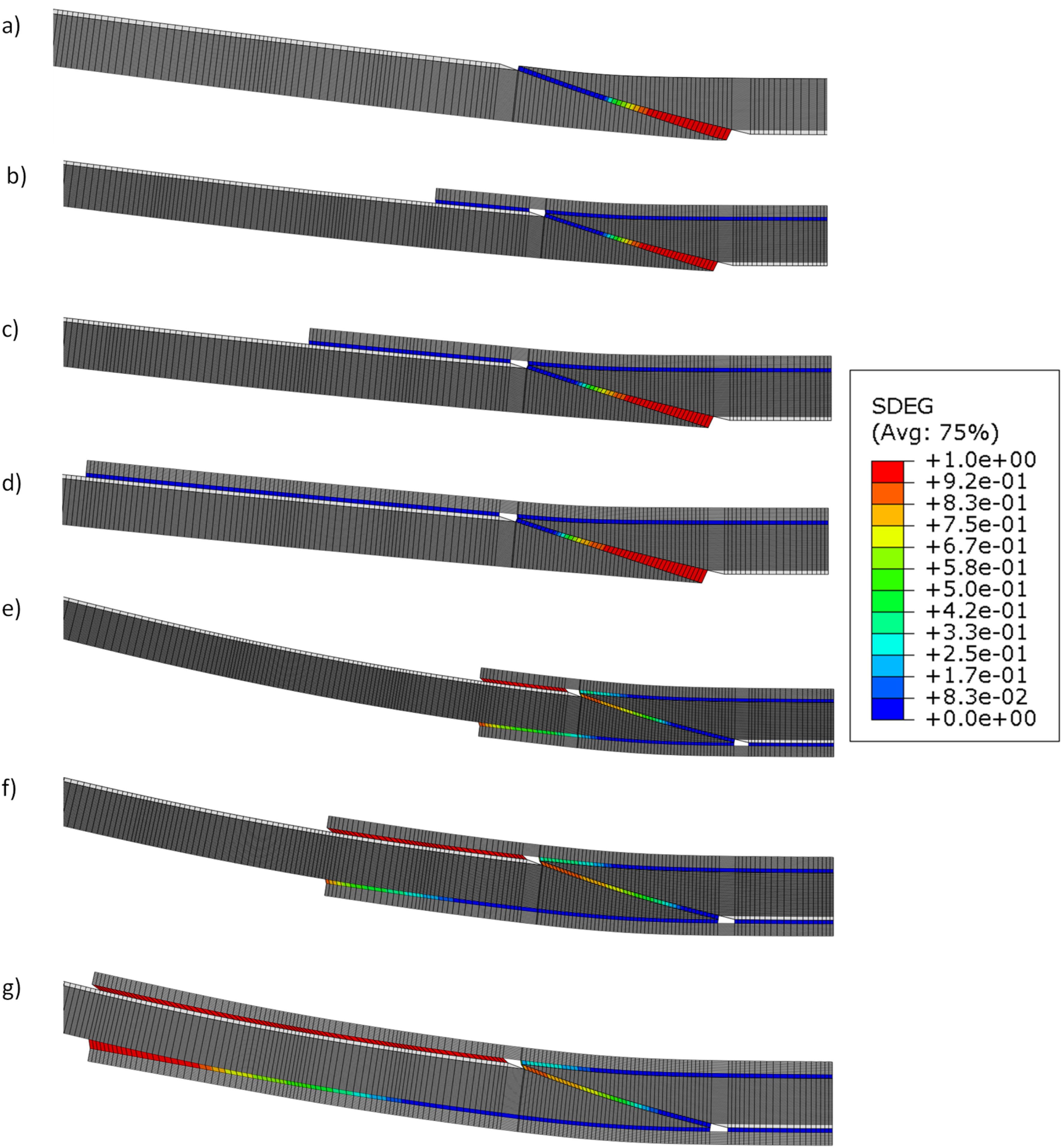
Turning to the Step joint bending results in Figure 15, and the unreinforced case (Figure 15(a)) shows the lower part failing first due to peel stresses. When only upper reinforcement is used (Figure 15(b) and Figures 15c and 15(d)), the failure mode is similar to the unreinforced case, since the critical lower layer remains unreinforced. With both reinforcements (Figure 15(e)–15(g)), significant shear stress develops at the overlap region of the upper and lower reinforcements inducing damage onset. Step repair results in bending load simulations: a) No Reinf.; b) 5 mm upper reinforcement; c) 10 mm upper reinforcement; d) 20 mm upper reinforcement; e) 5 mm full reinforcement; f) 10 mm full reinforcement; and g) 20 mm full reinforcement.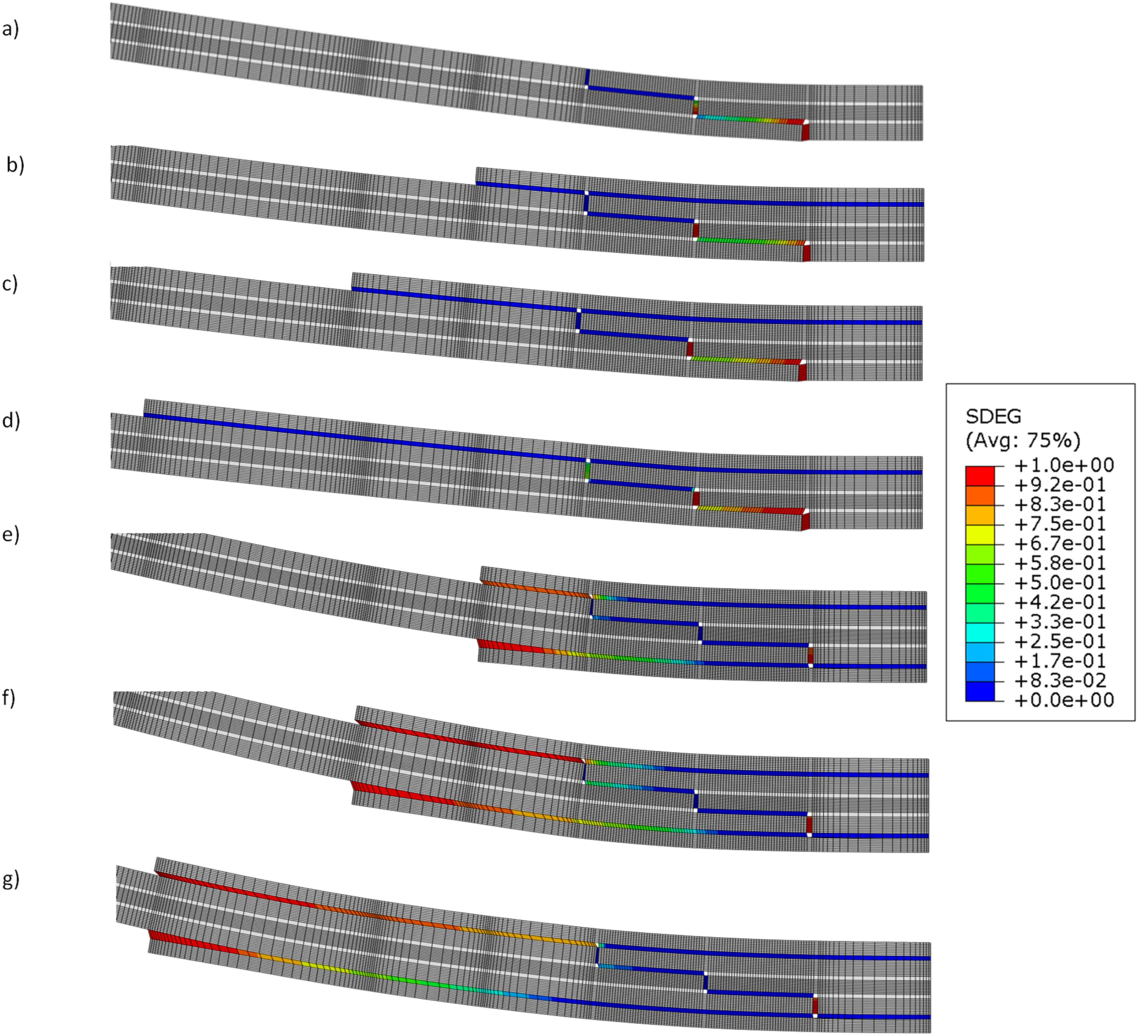
Scarf vs Step repairs
A comparison between the two types of repairs was performed considering the overlap of 10 mm and the two extreme cases: without reinforcement and full reinforced with doublers of 20 mm. Figure 16 shows the results for tensile and bending loading. It can be stated that remarkable and similar improvements of strength are obtained for the two cases, which reveals that this strategy is quite efficient regarding bonded repairs of damaged composites. Comparison between Scarf and Step repairs: a) tensile loading and b) bending loading.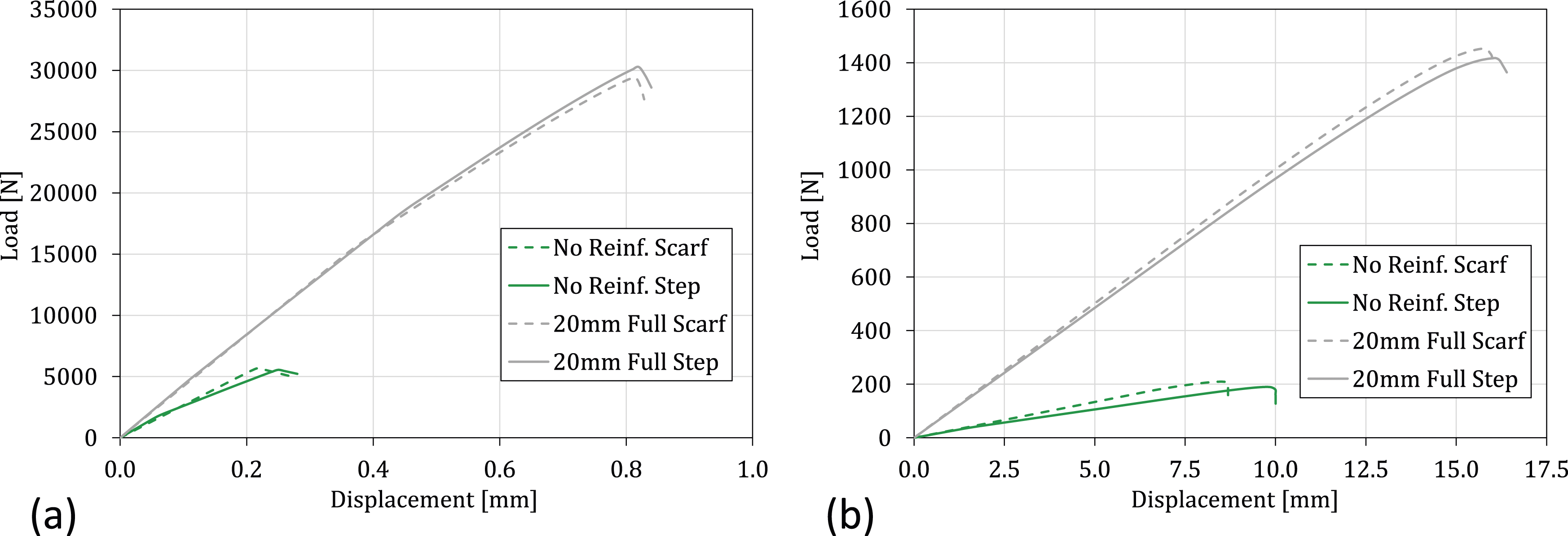
Conclusions
The numerical analysis carried out on the tensile and bending behaviour of carbon fibre reinforced polymer structures bonded repaired with external reinforcements, using Araldite® 2015 epoxy adhesive, provides valuable information for optimising repairs in the aeronautical industry. The study focuses on two repair geometries: Scarf and Two-Stepped, considering variables such as overlap length, reinforcement lengths, and the position of the reinforcement. Numerical simulations of tensile and bending loading were performed, resulting in a comprehensive exploration of 84 different geometric configurations and loading conditions. This parametric study emphasises the influence of overlap length and the configuration of external reinforcements. A stress analysis was performed aiming to identify the critical zones and the influence of the design parameters considered in this study. The outcomes in terms of maximum failure load and displacement at failure vary based on reinforcement length and configuration, underscoring the sensitivity of tensile behaviour to these parameters. In the tensile loads, Step repairs outperform Scarf repairs. Moving to the bending results, Scarf repairs exhibit an increase in strength, with the increase of the overlap length. The introduction of both reinforcements significantly alters the failure path, highlighting the importance of reinforcing critical zones. Unlike the tensile load, the results of the bending case highlight consistent improvements in stiffness with the introduction of reinforcements, while the displacement at failure does not uniformly increases due to non-uniform deformation.
The failure analysis, conducted using ABAQUS® and the SDEG parameter, provides nuanced insights into the failure paths of Scarf and Step repairs. In Scarf repairs, the failure paths are influenced by the presence of reinforcements, particularly in the tensile load, where the upper reinforcement or both reinforcements significantly modify the failure path. In Step repairs, the failure path remains relatively consistent in the tensile load. Regarding bending loading, the study reveals differences between Scarf and Step repairs in response to reinforcements. While both joints benefit from reinforcements, the impact on failure paths differs, especially in bending. The inefficiency of upper reinforcement alone in altering the failure path emphasises the relevance of considering the configuration of two reinforcements. In addition, it was verified that the introduction of external reinforcements significantly enhances the mechanical strength of the repaired joints, resulting in substantial improvements in the failure load that led up to a pronounced increase. This highlights the potential for optimising repairs in the aviation sector, leading to both environmental and economic benefits.
In conclusion, these numerical analyses contribute to a better understanding of the tensile and flexural characteristics of carbon fibre reinforced polymer structures bonded repairs with external reinforcements. The knowledge acquired contributes to the advancement of basic expertise for improving repair strategies in the aviation sector. This, in turn, provides better structural integrity and a reduction in environmental impact and economic aspects.
Footnotes
Acknowledgements
The authors acknowledge Fundação para a Ciência e a Tecnologia (FCT) for its financial support via the project LAETA Base Funding (DOI: 10.54499/UIDB/50022/2020).
Declaration of conflicting interests
The author(s) declared no potential conflicts of interest with respect to the research, authorship, and/or publication of this article.
Funding
The author(s) disclosed receipt of the following financial support for the research, authorship, and/or publication of this article: This work was supported by the undação para a Ciência e a Tecnologia (FCT) for its financial support via the project LAETA Base Funding (DOI: 10.54499/UIDB/50022/2020).
Data availability statement
The data given in this article are the datasets generated during and/or analysed during the current study and are available from the corresponding author on reasonable request.