
Abstract
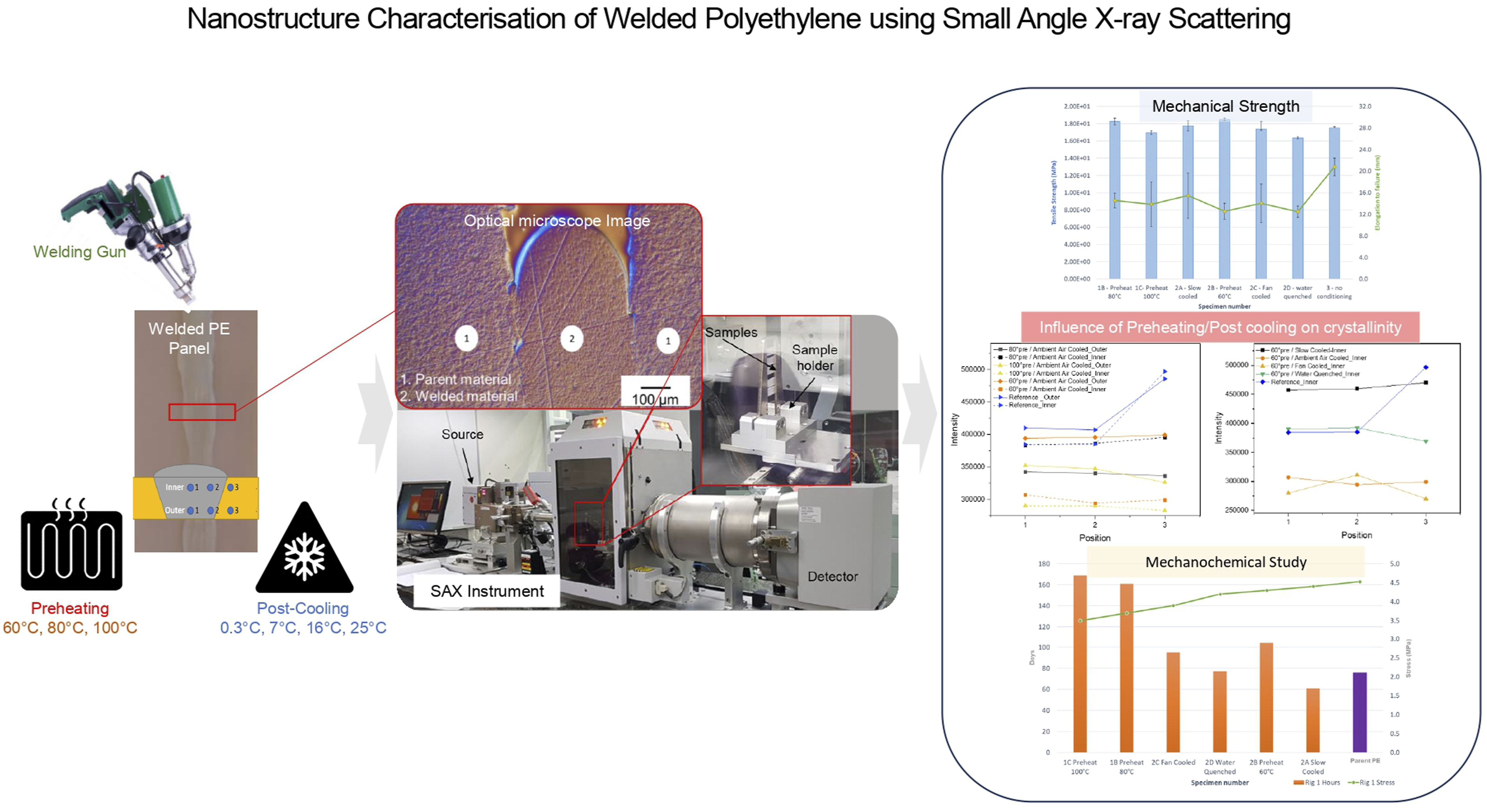
Polyethylene (PE), a common thermoplastic polymer, is gaining prominence in the construction and packaging industries due to its exceptional mechanical properties, chemical resistance, safety, and integrity. However, internal defects can occur during manufacturing and throughout its service life. Neglecting this problem results in the disposal of plastic and, consequently, the accumulation of plastic waste and environmental issues, which have caused much criticism. A common method to repair the thermoplastics is welding, which introduces seams and localized thermal residual stress fields resulting in areas where damage can nucleate, potentially leading to cracks and failure over time. These cracks often start at the nanoscale and propagate to larger length scales until failure occurs. The objective of this research paper is to develop welding processes, with improved integrity and lifespan for PE. Additionally, it aims to investigate and assess the impact of PE welding on parent materials at nano- and micron-scales, to understand limitations that are challenging to overcome in such welding processes. The study involves joining PE panels together under various pre-heating and post-cooling conditions, followed by evaluating the environmental stress cracking resistance of the welds and the durability of the repaired components. The crystallinity and morphology of the PE material in the weld area and its surrounding regions were analysed using Small Angle X-ray Scattering (SAXS), and the findings were compared with results obtained from optical microscopy and Differential Scanning Calorimetry. The study concludes that SAXS results offer exceptional information about the parent PE and weld material within the welding zone.
Introduction
Polyethylene (PE) is one of the most commonly used thermoplastic polymers which is widely used in various industrial applications. This is due to its excellent mechanical properties, chemical resistance, reproducibility,1–5 and cost-effectivity.
6
Its applications may include, but are not limited to, containers, agricultural films, heavy-duty shipping sacks in the packaging industry,7,8 as well as gas and water pipelines in water treatment, desalination, mining, and construction industries.6,9,10 However, they are subjected to occasional damage during manufacturing and service life. The inability to reuse and recycle them leads to severe environmental issues. Welding is a viable means of repair for thermoplastics such as PE. Nevertheless, welding process causes the introduction of seams, which are known weak points, and a localized thermal residual stress fields within the welds and surrounding parent materials.
11
Thermoplastic weld seams are known failure points, which can crack and lead to failure over time.10,11 These cracks may occur due to the difference in the crystallinity of the welded zone material compared to the parent material. The structure of semi crystalline material is shown in Figure 1. Semi crystalline structure.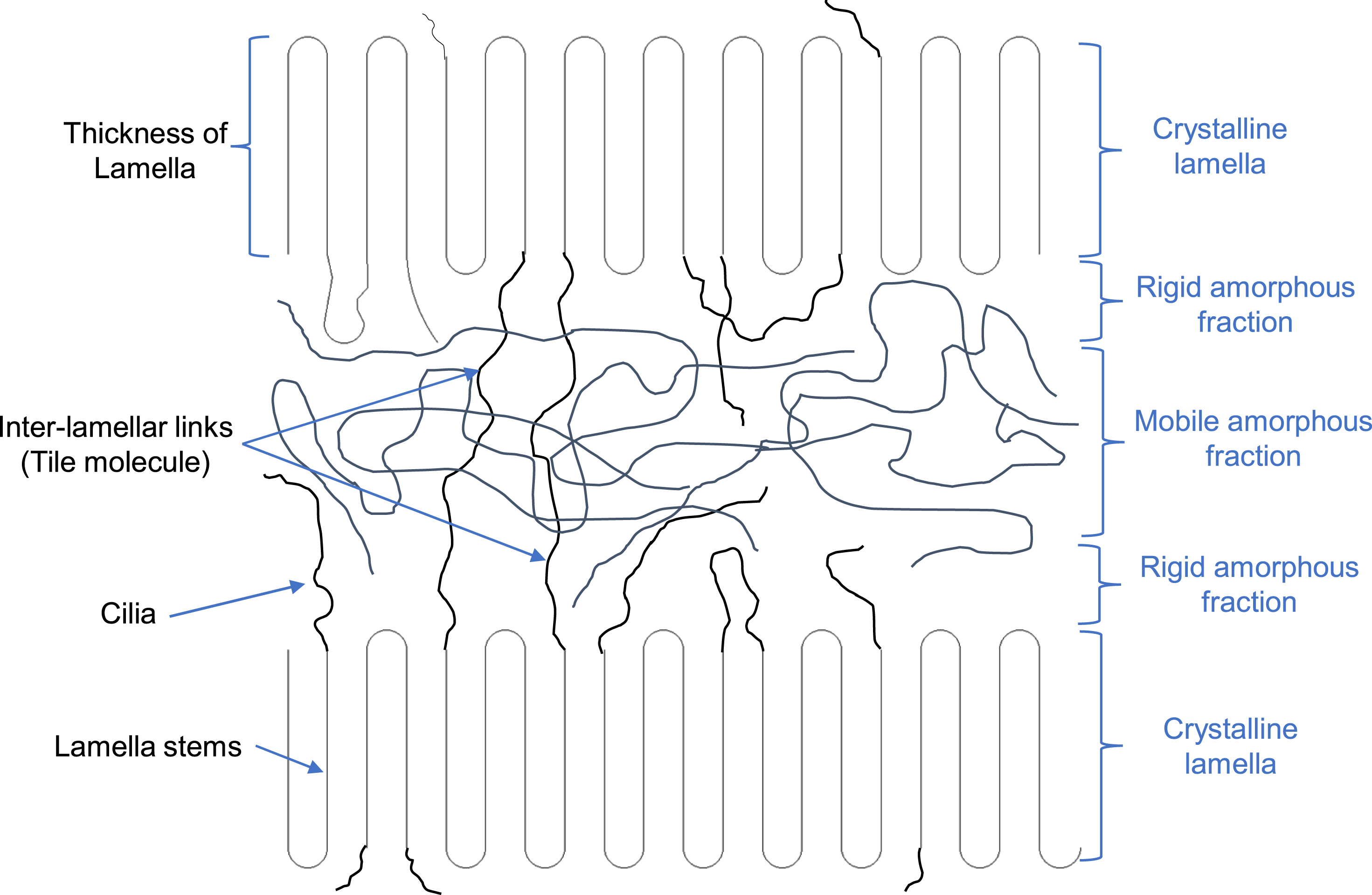
In earlier research, 12 it was shown that the crack behaviour in melt-crystallized poly (L-lactic acid) (PLLA) depends on molecular weight and crystallinity. With increasing molecular weight in PLLA, the degree of crystallinity decreases, and cracks are less likely to occur. While multiple types of cracks, including circumferential and radial, will create in low-molecular weight PLLA, which has high crystallinity.
The relationship between polymer chain microstructure, formation, and morphology of crystalline domains and resistance to slow crack growth in polyethylene pipe materials (PE100 polyethylene resins with different short-chain branch distributions and almost identical average molecular weight) has also been investigated. Creep test results show that samples prepared using a lower crystallization rate and lower Avrami index are more resistant to slow crack growth (SCG), which is the result of the crystalline morphology presenting obstacles to crack development and propagation. 13
Even if cracks are not expected to be catastrophic, they may result in the need for repair operations, which may affect product integrity. The performance characteristics of PE products, such as pipelines and containers, depends considerably on welded joint quality. Hence, it is essential to have efficient and reliable repair technology 10 to ensure the quality of welds and surrounding heat-affected zones. Investigations of the morphology of welded joints have focused on the macrostructure, fusion lines, and heat-affected zone geometry in the welded PE parts.6,14,15 Several studies have been conducted on welding techniques, crystallinity analysis, and modelling of PE welded joints.
The molecular structure, crystallinity, and morphology of three types of polyethylene/polypropylene (PE/PP) blend, including high-density polyethylene (HDPE)/PP, linear low-density polyethylene (LLDPE)/PP, and metalloance PE/polypropylene (MEPE/PP) have been investigated using Raman spectroscopy, Raman mapping, scanning electron microscopy (SEM), wide-angle X-ray diffraction (WAXD), and differential scanning calorimetry (DSC). Raman mapping and SEM images show that the MEPE/PP blends with the large melt flow index (MFI) ratio have different dispersibility behaviour compared to the HDPE/PP and LLDPE/PP blends with small MFI ratios. The X-ray diffraction patterns in HDPE/PP and LLDPE/PP blends are sharper than the MEPE/PP blends. The DSC crystallization and fusion areas of the HDPE/PP, LLDPE/PP, and MEPE/PP blends change linearly as a function of the blending ratio. The blending ratio of HDPE/PP and LLPE/PP does not affect the melting temperature of HDPE, LLPE, and PP in the blends. However, increasing PP contents in MEPE/PP increases the melting temperature of the blend. It is also shown that MEPE has a significant influence on the crystallinity of PP. Thus, a combination of these techniques will comprehensively study the morphology, structure, and physical properties of the PE/PP blends. 16
The weld analysis of dissimilar types of PE (PE-80 and PE-100) has been conducted through DSC, WAXS, thermogravimetric, and thermomechanical analyses. In this study, the PEs were welded using traditional hot tool butt welding, using a heating rate of 10°C/min, performed within a temperature range of 30 to 250°C. The results reveal that the welding process leads to a restructuring of crystalline phases, giving rise to crystalline regions with improved mechanical and thermal properties. This enhancement is a result of an increased quantity of crystallites, larger in size, and exhibiting better ordering within the material. 6 The relaxation behaviour of dissimilar PE welded joints (PE-80 and PE-100) also was studied using WAXS, SAXS, DSC, and thermal analysis. The same welding technique was used for a hot tool butt (200°C). It is shown that the relaxation occurs within 1 year in the amorphous and crystalline phases with respective changes in PE properties. 17 To study the correlation between the melting and solid state of heterogeneous PE, SAXS was used for a blend of HDPE and LDPE. It is shown that the disorder in the blend of two PEs with different melting and crystallization temperatures is more than in a homogeneous PE treated under the same thermal condition, and its morphology depends on the cooling rate. 18
A series of analysis techniques, including SAXS, WAXS, thermal, and microscopy, to investigate the polyhedral oligomeric silsesquioxanes (POSS) dispersal, crystalline morphology, and crystallization kinetics of the host polymer in. 19 In this study, novel octakis octasilsesquioxane (Q8M8) molecules were octafunctionalised with octadecyl alkyl-chains (Q8C18) and blended with 0.25–10 wt% loadings into a commercial LDPE. The results show that POSS particles dispersed well in the host polymer up to 5 wt% loadings and acted as nucleating agents without disrupting the crystal lattice of the PE. Beyond 5 wt% loading, the POSS aggregate reduces the bulk crystallinity and hinders the crystallization process. The aggregation of POSS is attributed to increased POSS–POSS interactions whereby the POSS molecules self-assemble in an interdigitated manner. The results were compared with an analogous LDPE–T8C18 POSS cage blend at 10 wt% loading. In contrast, the T8 POSS particles disperse well in the host polymer, effectively nucleating agents and increasing the bulk crystallinity. This may have important implications in the processing of polyolefins, where the T8 system acts to accelerate crystallization, whereas the Q8 system retards it.
A method for analysing the lamellar stacks of crystalline polymers was developed utilizing SAXS. 20 A complete set of scattering functions is constructed on a self-contained basis of a paracrystalline stacking model of a finite number of lamellae in a stack with border zones, and the applicability to typical crystalline polymers, polybutylene terephthalate (PBT), and polyethylene (PE) has been examined experimentally. The results indicate that PBT does not exhibit banded crystals, suggesting the presence of a parallel arrangement of flat lamellar crystals instead. Also, the chains in the crystals are less mobile. Hence, it will not easily thicken and become thinner than amorphous layers like polyethylene terephthalate (PET). On the other hand, PE forms banded spherulites under relatively high supercooling. Thus, parallel stack of lamellar crystals twisting along their long axis is geometrically complex. The chains are mobile in the PE crystals, so they would easily thicken and be thicker than amorphous layers. The analysis results confirm that, unlike PBT, the SAXS pattern of PE could not be fitted using the modelling with an infinite sequence and needed the consideration of the cases of a small number of sequences. Also, this result of PE forming a banded spherulite is by the three-dimensional structure of individual PE lamellar crystals, which twist along their own long axis geometrically and disable the simple stacked structure of an infinite number of lamellae oriented parallel to each other in a stack. 20
The crystallinity of PE also is directly correlated with environmental stress cracking (ESC) resistance.21,22 It is shown that, lower percentage crystallinity and thinner lamellar can result in a larger extent of interlinear linkages, which ultimately increase the cracking resistance of PE. 21
All these investigations have studied the morphology and crystallinity of PE in different blends welded using traditional techniques, and there is no improvement in the welding technique. During the welding process, the material in the welded zone undergoes melting, deformation, and molecular interpenetration, followed by recrystallization. The new structure is formed under the imposed stress state of the welding process which needs further investigation.
Hence, in this investigation, a reliable technique is implemented to weld uncluttered PE panels under differing pre-heating and post-cooling conditions. SAXS is used to understand and evaluate the effect of the welding process on the crystallinity of the welded zone materials versus the parent materials. The obtained results then were compared with optical microscopy and DSC analysis for verification. Since, ESC is a significant concern in industries where plastic materials are used for components or containers, such as in the automotive, packaging, and chemical industries, the crystallinity of the welded materials was investigated under different mechanochemical test conditions.
Experimental program
Sample preparation
Thermoplastic welded panels
The thermoplastic parent panels that were used in this experimental study are made of PE sheet. In total seven panels were prepared for this experimental program. The panels’ dimensions were 350 mm × 350 mm with a total thickness of 10 mm. A slot of 300 mm × 3 mm was created at the middle of panels using a circular saw blade, as shown in Figure 2. (a) Test Setup for welding panels; (b) Manufactured PE panels with slot for application of different welding conditions; (c) Weld line.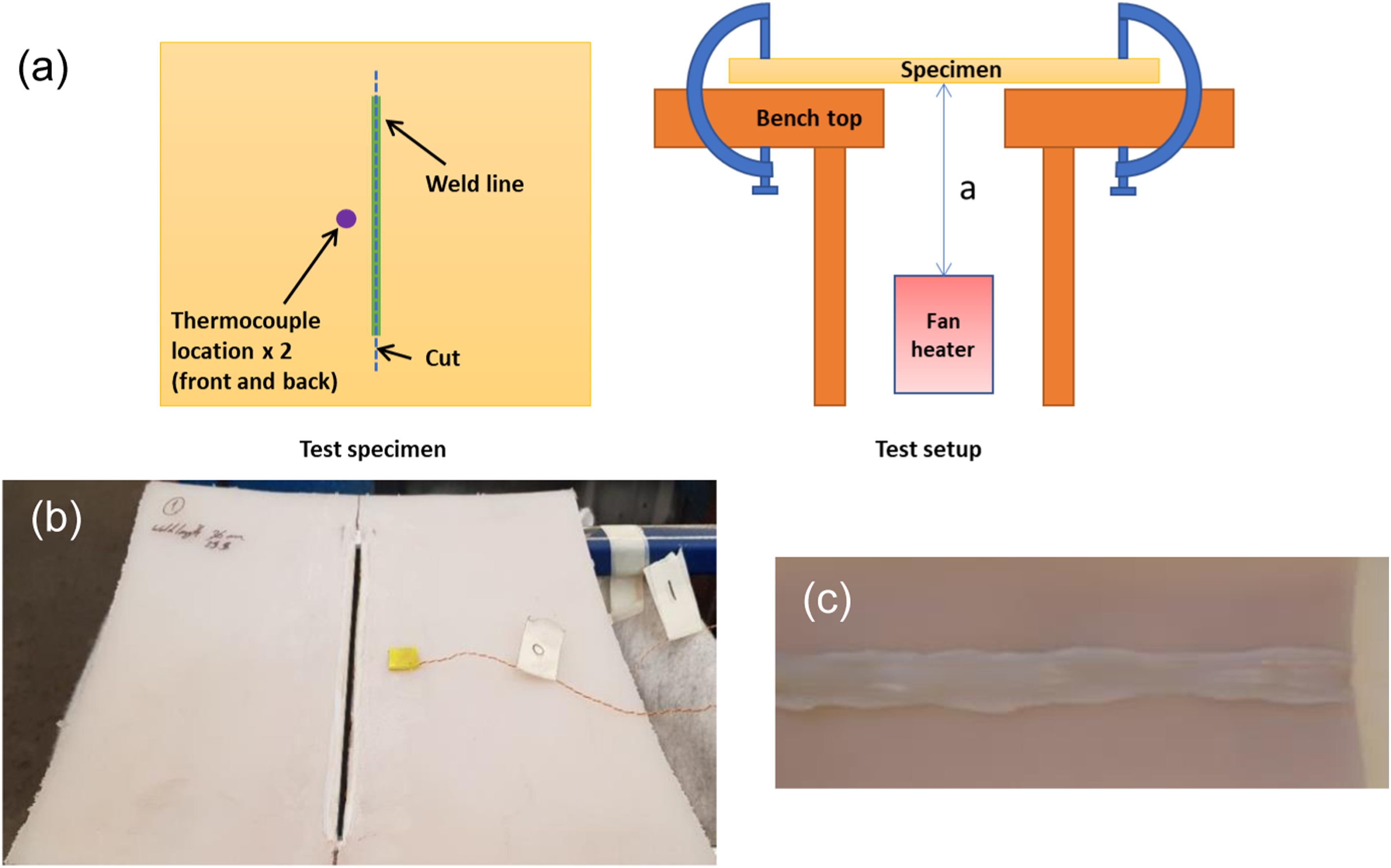
Pre-heating and post-cooling conditions.
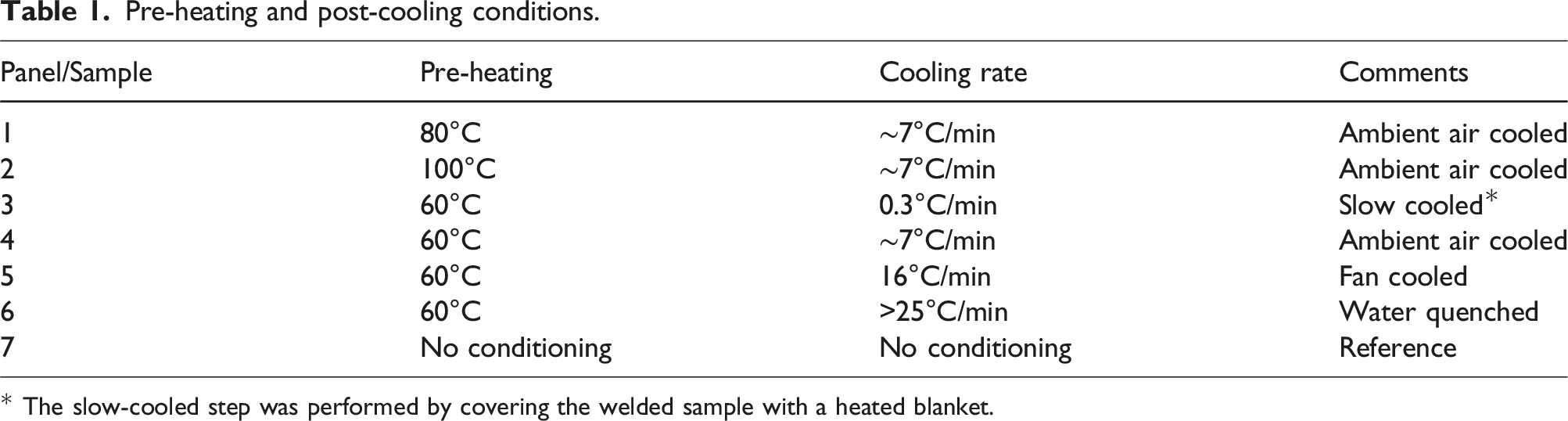
* The slow-cooled step was performed by covering the welded sample with a heated blanket.
Small angle X-ray scattering (SAXS) test samples
SAXS experiments on the thick samples are not desirable due to the increased sample absorption. Therefore, the sample thickness should be chosen according to the respective absorption. In a preliminary investigation, in order to study the effect of sample thickness on the SAXS results, samples with five different thicknesses from 0.25 mm to 1 mm (0.25, 0.5, 0.75, 0.9, and 1.0 mm) were cut from the reference panel (non-welded region), using low-speed diamond saw. The samples are shown in the SAXS holding fixture in Figure 3. After confirmation of sample thickness (0.25 mm) from initial investigation, samples with thickness of 0.25 mm were cut from the welded zone to study the effect of processing condition on the crystallinity of the PE. (a) PE samples with five different thicknesses positioned on SAXS instrument scanning frames; (b) Samples collected from the welded zone under different pre-heating and post-cooling conditions.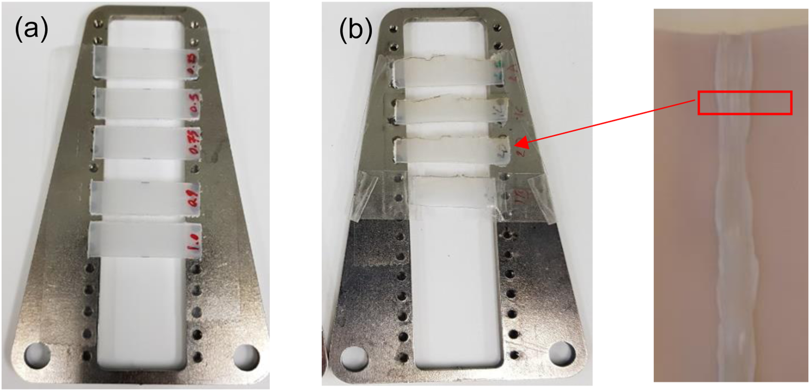
Mechanical testing
Tensile test
To study the effect of processing condition on the strength and failure mode, tensile testing was conducted on the welded samples. Three samples were prepared from each processing conditions for statistical reliability. The test machine, sampling, and test procedure were in accordance with the ISO 6259-3 standard using a uniaxial electro-mechanical test machine (Instron-3369) with a 50 kN load cell. The specimens were tested under displacement control at a constant loading rate of 0.5 mm/min. The failure mode for each sample was recorded after the test. The experimental setup for the tensile test is shown in Figure 4. The ultimate tensile strength of the weld could be used as a quality control of the weld procedure. Tensile test experimental set-up.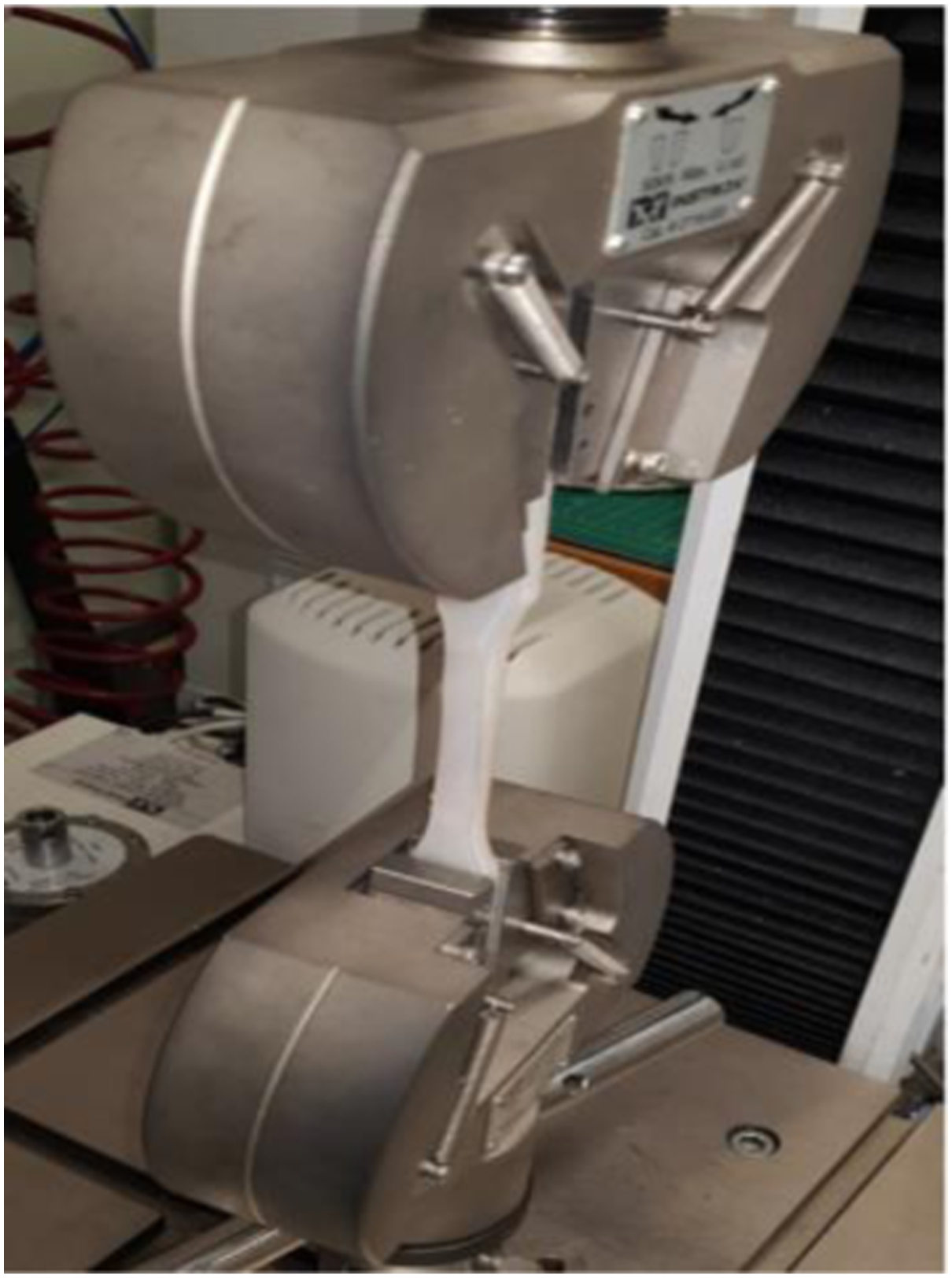
Mechanochemical test
In order to confirm the resistance of the weld to ESC and assess the durability of the repair concept, the welded samples were loaded into a specially designed rig submerged in sulphuric acid (98% H2SO4), Figure 5. The samples were loaded to a stress level of between 3.5 MPa and 4.4 MPa, in direct tension, for a period of up to 169 days. Custom made test rig for mechanochemical test.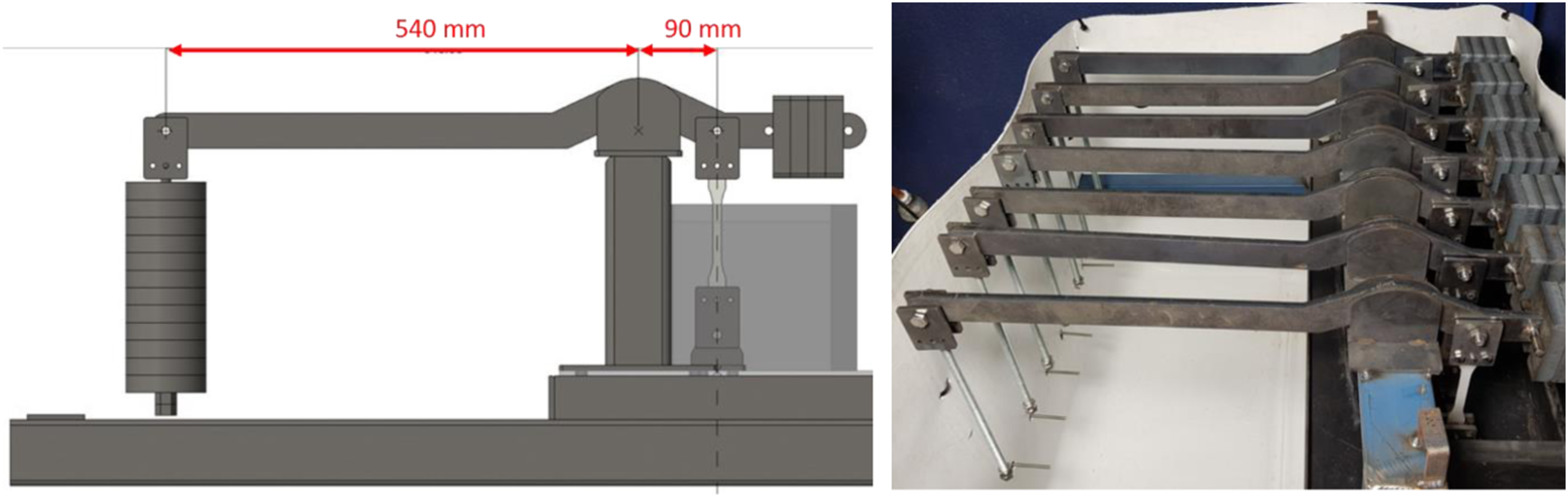
Small-angle X-ray scattering (SAXS)
The performance of many advanced materials is dependent on their nano and microstructures. To study the crystallinity and morphology of PE in the weld and surrounding area, laboratory SAXS measurements were conducted using the Bruker Nanostar SAXS instrument at ANSTO in Lucas Heights, Australia, as shown in Figure 6. The instrument features a rotating copper anode that emits Kα radiation with a wavelength of λ = 1.541 Å. The sample-to-detector distance is 720 mm, providing a q range of 0.005–0.35 Å
−1
, where q is the scattering vector defined as q = 4πsin(θ/2)/λ, with θ being the scattering angle. The initial two-dimensional detector images capturing isotropic scattering patterns were processed using Bruker software and the instrument’s specific geometry. This processing resulted in the conversion of these images into a one-dimensional form known as I(q), which represents the intensity of scattered radiation as a function of the scattering vector q. SAXS also can be used to study of density variations, colloidal sizes, particles sizes, porosity, domain sizes, orientation, and phase identification, the list is endless. With research being directed more towards nano-sized science, SAXS is becoming a widely used tool. Bruker SAXS instrument at ANSTO.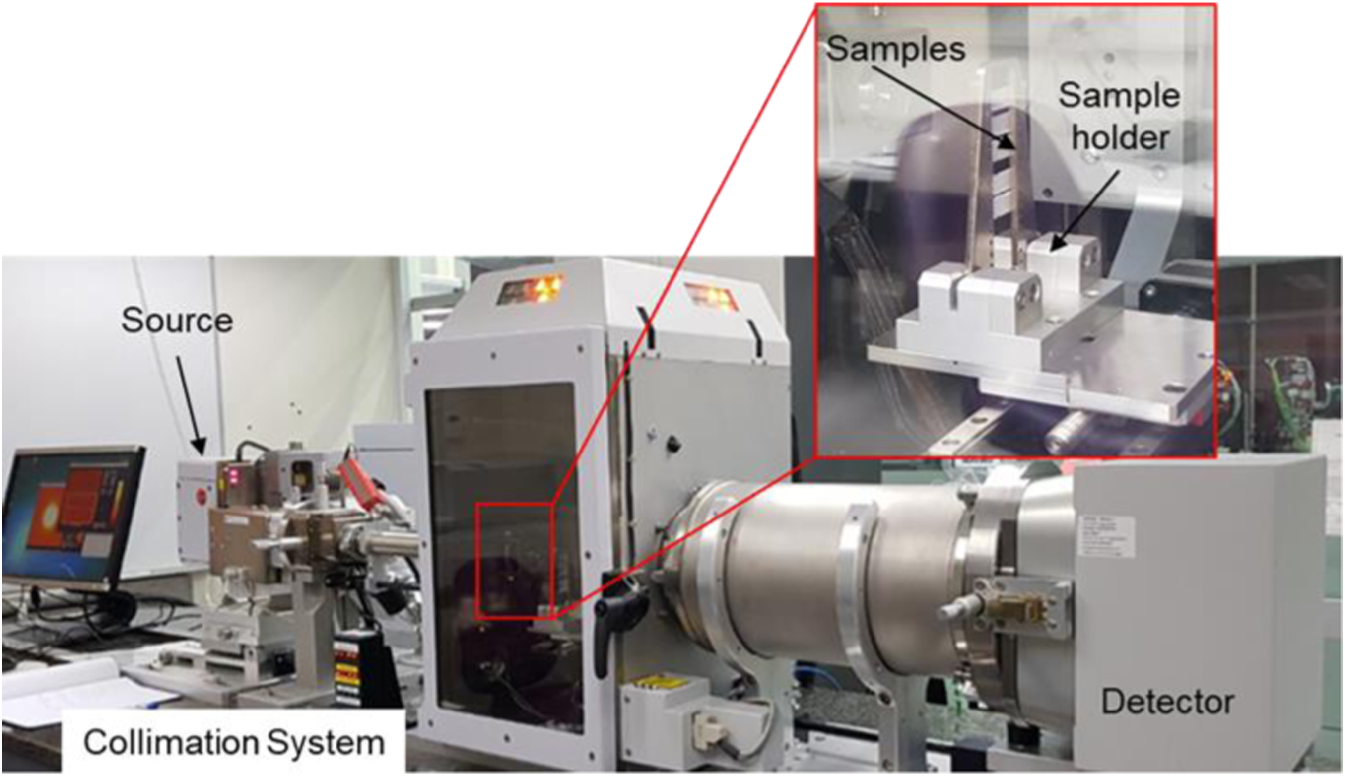
The main components of SAXS instrument include a source, collimation system, sample holder, beam stop, and detection system. During the measurement process, the samples irradiated with source after the beam becomes narrow (zero-angle position) through the collimation system. The detector measures the radiation coming from the sample in a certain range of angles, and the beam stop prevents the intensive incident transmitted beam hitting the detector. To keep the background scattering low, it is required to hold the samples in a vacuum. The samples were mounted on special sample holder. The mounted samples then were placed into a measurement compartment and vacuum were applied.
Effect of sample thickness on crystallinity
The research conducted by Ji et al.
23
on how to avoid multiple scattering in strongly scattering samples using Small Angle Neutron Scattering (SANS) and Ultra Small Angle Neutron Scattering (USANS) has revealed that the average number of scattering events per neutron increases linearly with the length of the neutron path. Consequently, the occurrence of multiple scattering (MS) is possible, necessitating specialized modelling for result deconvolution. To avoid this issue, it has been advised to reduce the sample thickness to less than 0.15–0.5 mm. Thus, in this study as a preliminary investigation, the effect of sample thickness was studied on PE samples with different thicknesses (0.25, 0.5, 0.75, 0.9, and 1.0 mm), from non-welded region. For this purpose, the samples were mounted on SAXS scanning frame (sample holder) and five points were measured along the centre line of each sample. Each measurement took about 1.5 hours. The obtained results plotted in Figure 7(a). (a) Preliminary measurement on the reference sample and the original results from SAXS (study the effects of thickness); (b) Calculation of q
Peak
for d-spacing; (c) Reduced intensity and calculation of d-spacing based on the q
Peak
for the 3rd point (at the centre) in all samples.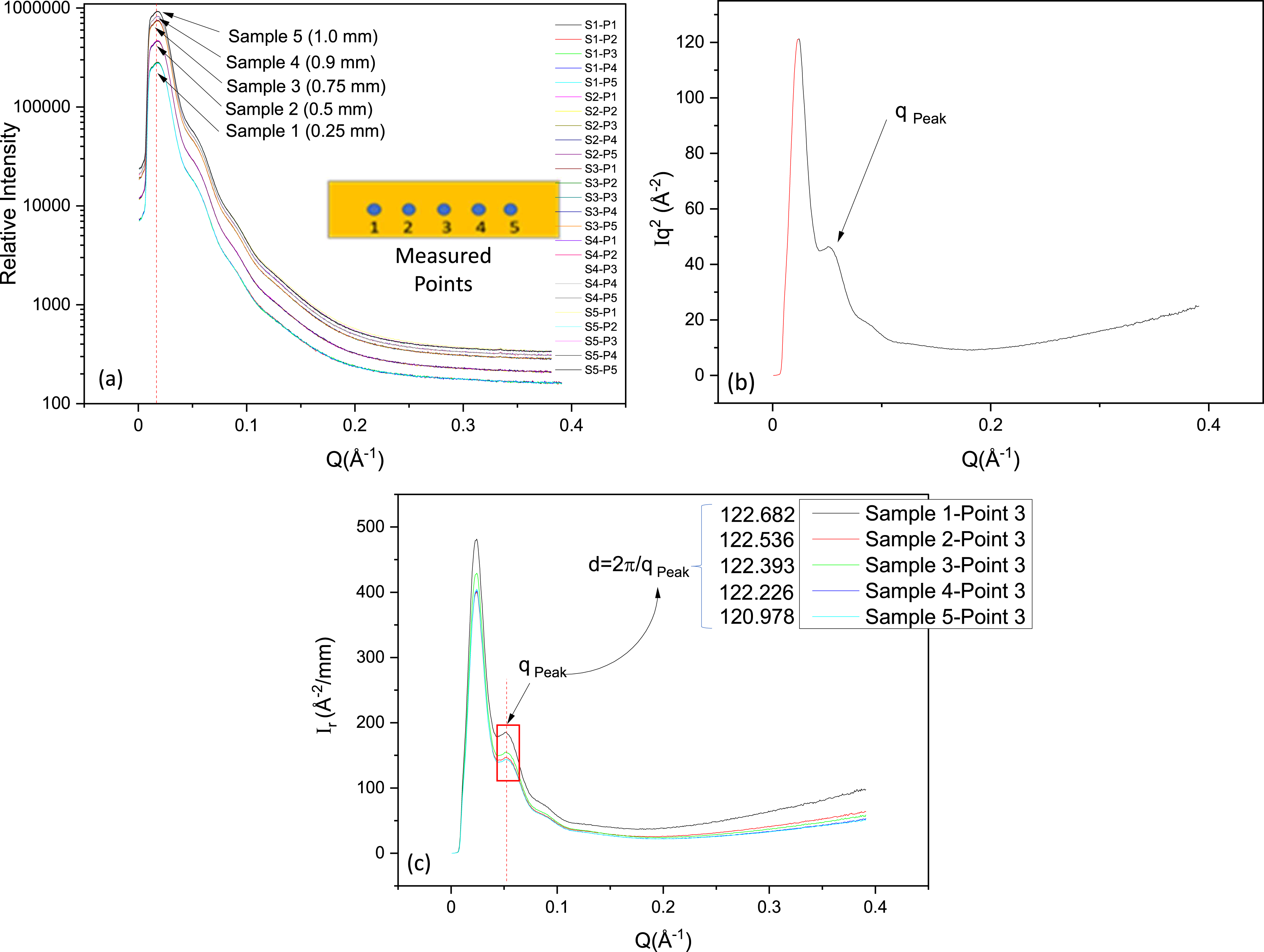
To calculate the distance between planes of atoms that give rise to different peaks (d-spacing), q
Peak
were calculated which refers to the maximum momentum transfer vector magnitude that can be measured in the experiment, Figure 7(b)
As the samples had different thicknesses, to calculate the reduced intensity (I
r
) after travelling a distance t through the material, the intensity of each sample was divided by the sample thickness. The reduced intensity is calculated as
Effect of processing condition on the crystallinity welded zone
A similar approach was implemented for the secondary investigation. In total six points, three points at outer layer and three points at inner layer, were measured using SAXS, Figure 8(a). The points were separated by 2 mm from each other in X, Y directions. The SAXS results were plotted in linear scale using shape independent using choosing ‘Gaussian Peak’ model. The information derived from the plots includes the peak’s sequence, positions, scale, width, intensity, and azimuthal distribution. This information represents the structure of crystalline materials and can be used to characterise the crystallinity. (a) SAXS plot of a semi-crystalline polymer (Green curve is the fitting profile of point 1 in sample 1); (b) Model parameters/fitting information using SasView.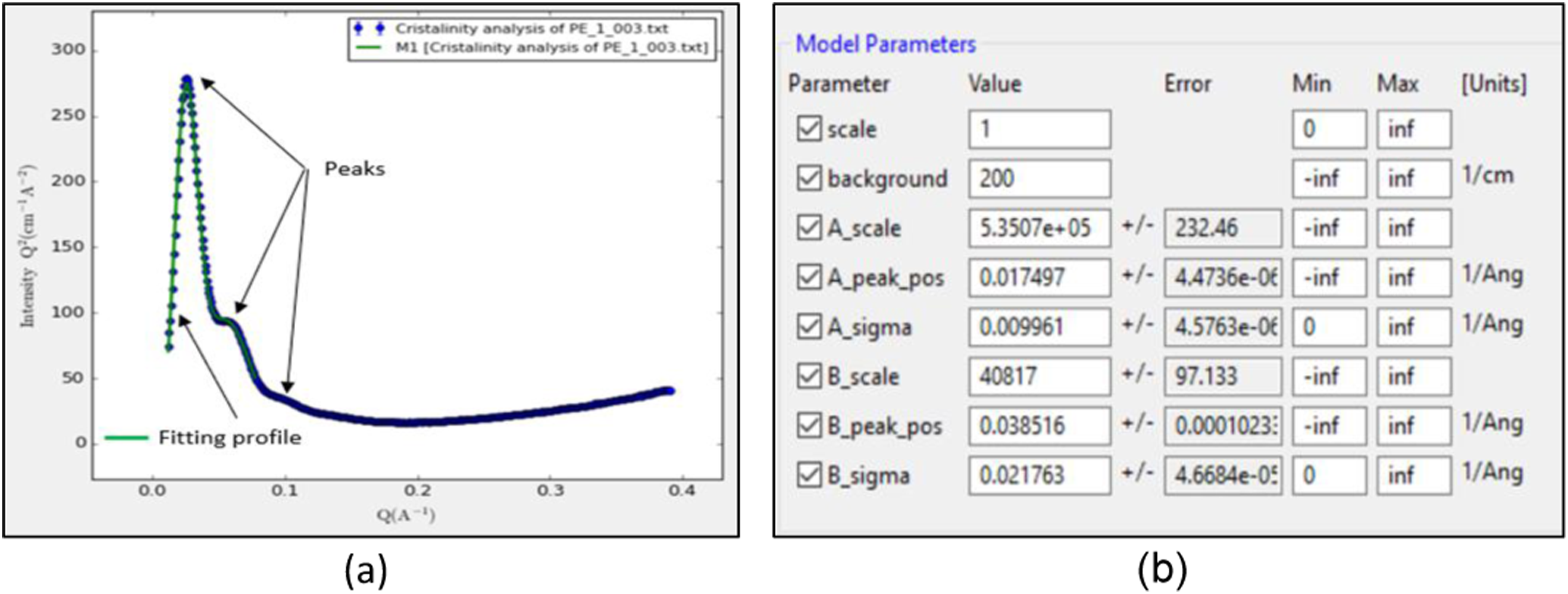
As it shown in Figure 8(a), three peaks were identified for each graph. To obtain the aforementioned information, fitting conducted using SasView software by adjusting the model parameters. Then, the obtained information form inner and outer layer of each sample were plotted based on each processing condition.
The key modelling parameters including scale, peak position, and sigma, derived from SAXS experiments (shown in Figure 8) have been examined for this purpose. The scale is related to the peak intensity. In SAXS analysis, a higher peak intensity indicates a higher density of scattering centres or structures with a characteristic size in the sample.
The peak positions refer to the angles at which the SAXS peaks occur in the scattering pattern. These peaks correspond to specific distances between scattering centres or repeating units within the material. By analysing the peak positions, the spacing between the lattice planes, known as the d-spacing can be determined. The d-spacing values are crucial in identifying the crystal structure, as they are characteristic of specific crystallographic planes and can be matched to known crystal structures in databases. Higher peak-position values in SAXS analysis indicate larger crystal dimensions and lower peak-position values indicate smaller crystal dimensions of nanoscale structures. Also, peak at higher angle has minimum interplanar spacing while at lower angle has maximum interplanar spacing.
Sigma referred to as the peak width or peak broadening. This refers to the phenomenon where the SAXS peaks in the scattering pattern become wider and less well-defined. The broadening of peaks is influenced by several factors, including crystallite size, micro strain, and instrument resolution. By analysing the peak width, better insights into the size and imperfections (such as defects or dislocations) present in the crystalline domains can be obtained. For example, a broader peak may indicate smaller crystallite size or higher lattice imperfections, while a narrower peak suggests larger crystallites and better crystalline quality.
Results and discussion
Mechanical strength
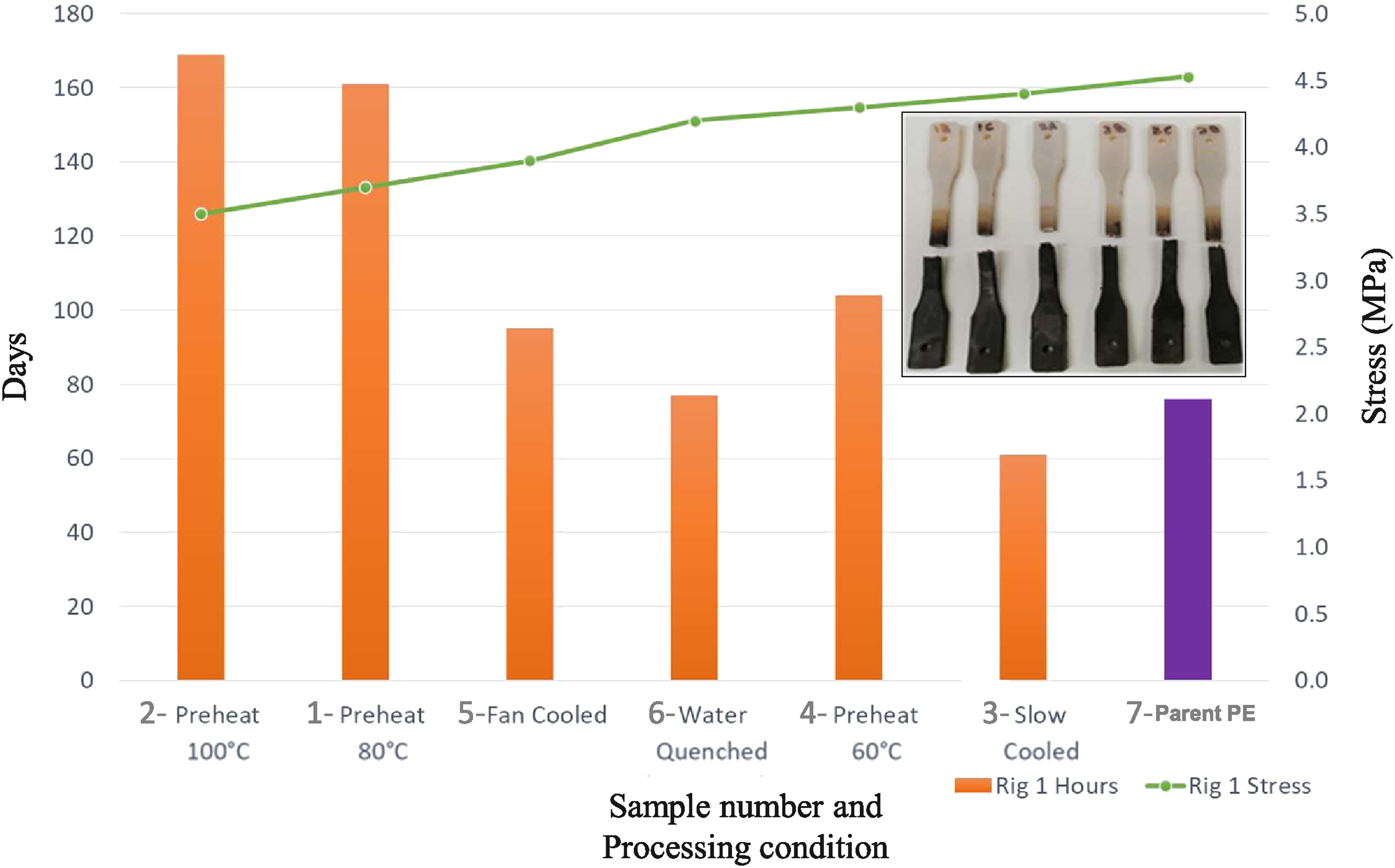
The mean values of the maximum tensile strength (blue bars) and measured elongation to failure (green line) of the tested specimens are presented in Figure 9. Standard deviation is calculated from the three specimens tested for each condition. Generally, the samples that underwent pre-heating at temperatures of 60°C and 80°C, with an ambient air-cooling rate ≤16°C/min, exhibited higher strength compared to the sample pre-heated at 100°C. Also, among the samples that were pre-heated at 60°C, Sample 4, cooled in ambient air at a rate of 7°C/min, demonstrated the highest strength. Whilst the sample 6 (water-cooled) exhibited the lowest strength among all the samples. Same trend is observed for the elongation to failure except for sample 7 (No conditioning) which has the highest elongation among all the samples. The tensile strength of welded samples.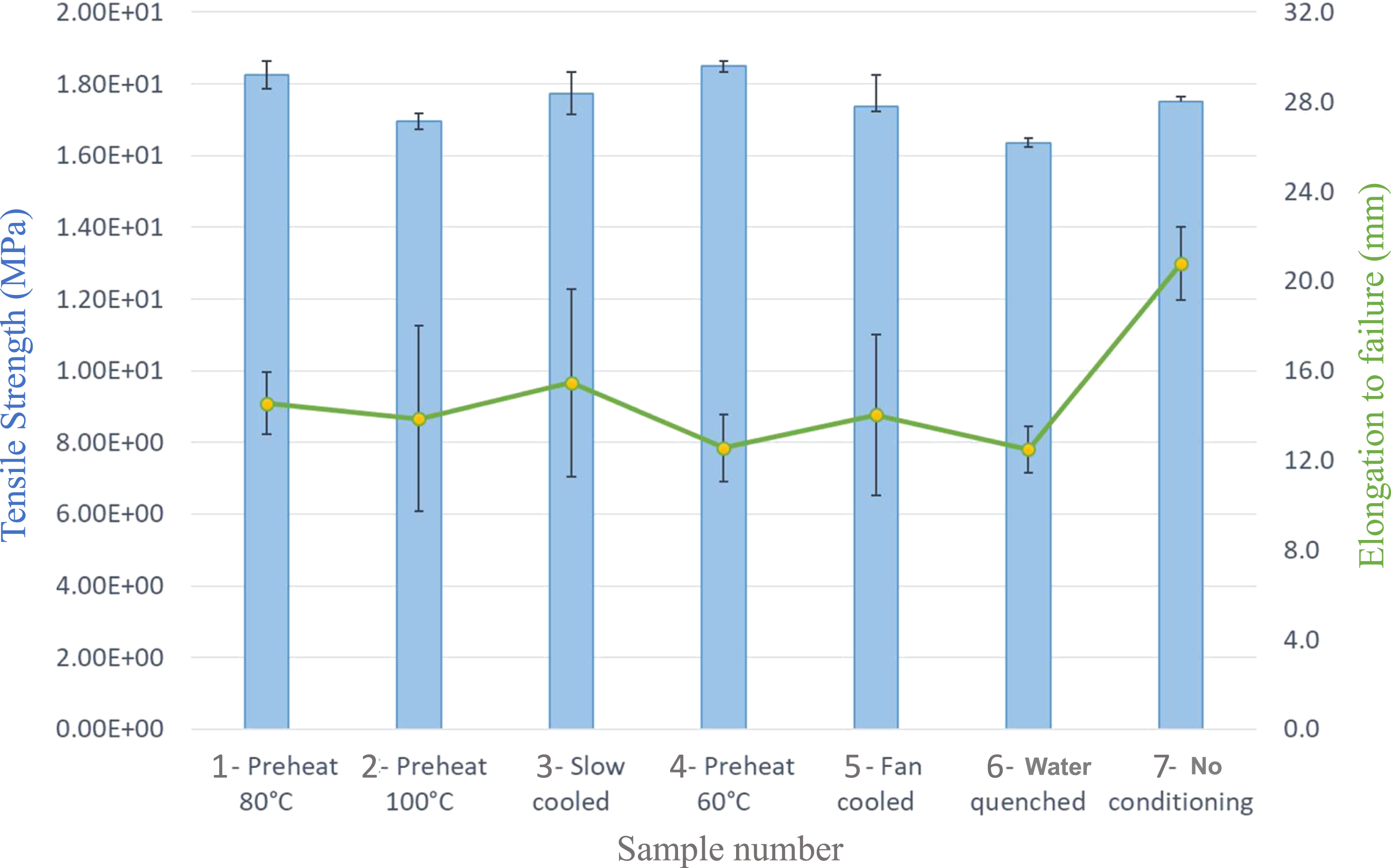
Microscopic analysis
In order to understand the effect of pre-heating and post-cooling conditions on the atomic and molecular structure of a single crystal, the crystallinity of the parent material and welding rod were analysed using Single-crystal X-ray Diffraction (SXRD) and recorded as 62.4 % and 63.2 %, respectively, Figure 10. The crystallinity of the parent material and welding rod were analysed using SXRD.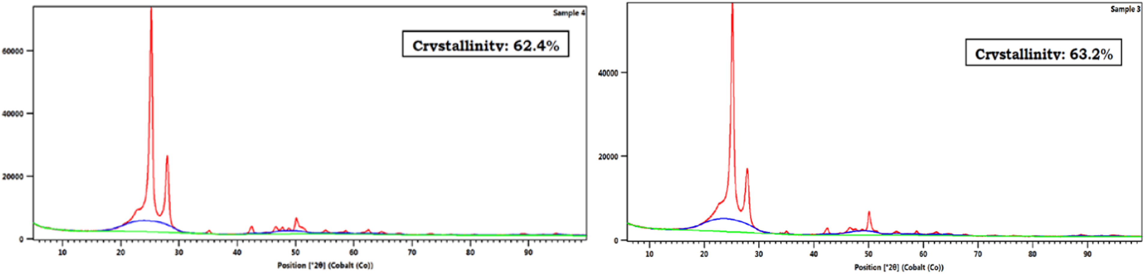
Thermal properties and transitions in parent material and welding rod, DSC was implemented to understand their behaviour. According to DSC results, the crystallinity of the parent material is 6.07% higher than the welding road, Figure 11. DSC plots with calculated crystallinity in % for parent material specimens.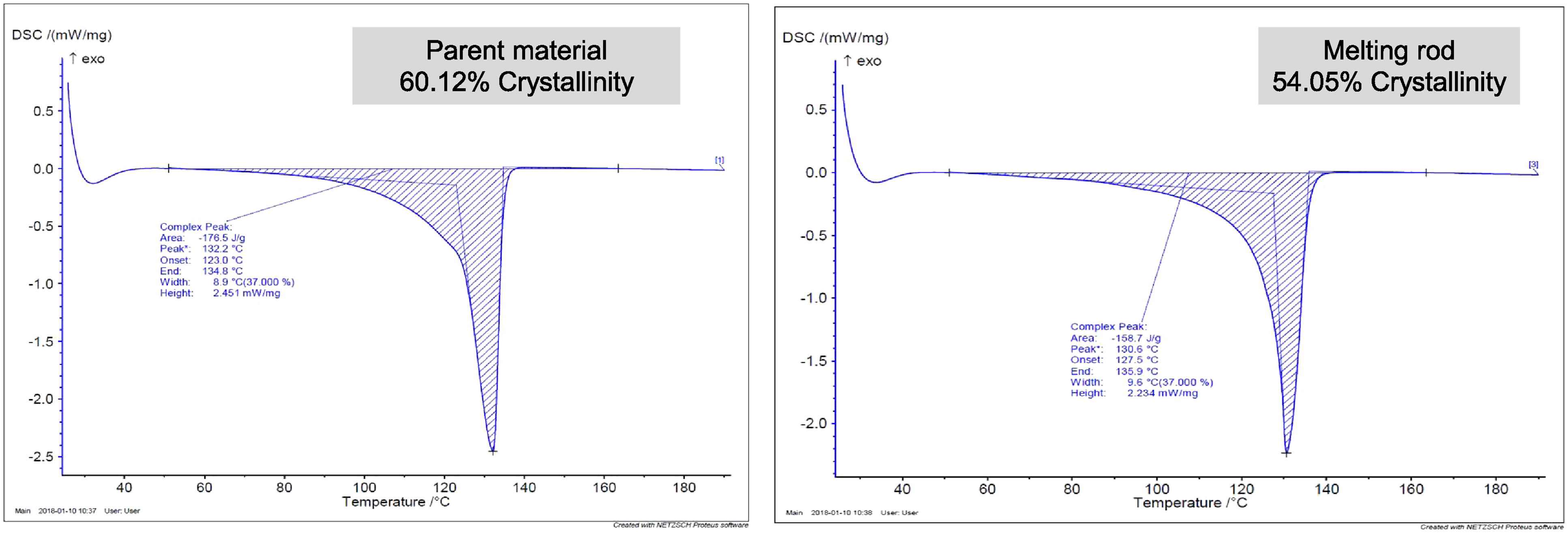
Following that, the crystallinity of the welded zone under different pre-heating and post-cooling conditions was measured and it was found that PE materials are sensitive to the welding process. According to SXRD results, the percentage of crystallinity under different conditions can reduce by 15.2%. DSC also confirms the hypothesis that by controlling the cooling it is possible to reduce the variation in percentage of crystallinity in the weld and heat-affected zone, as shown in Figure 12. Percentage of crystallinity variation on the pre-heated samples (60°C).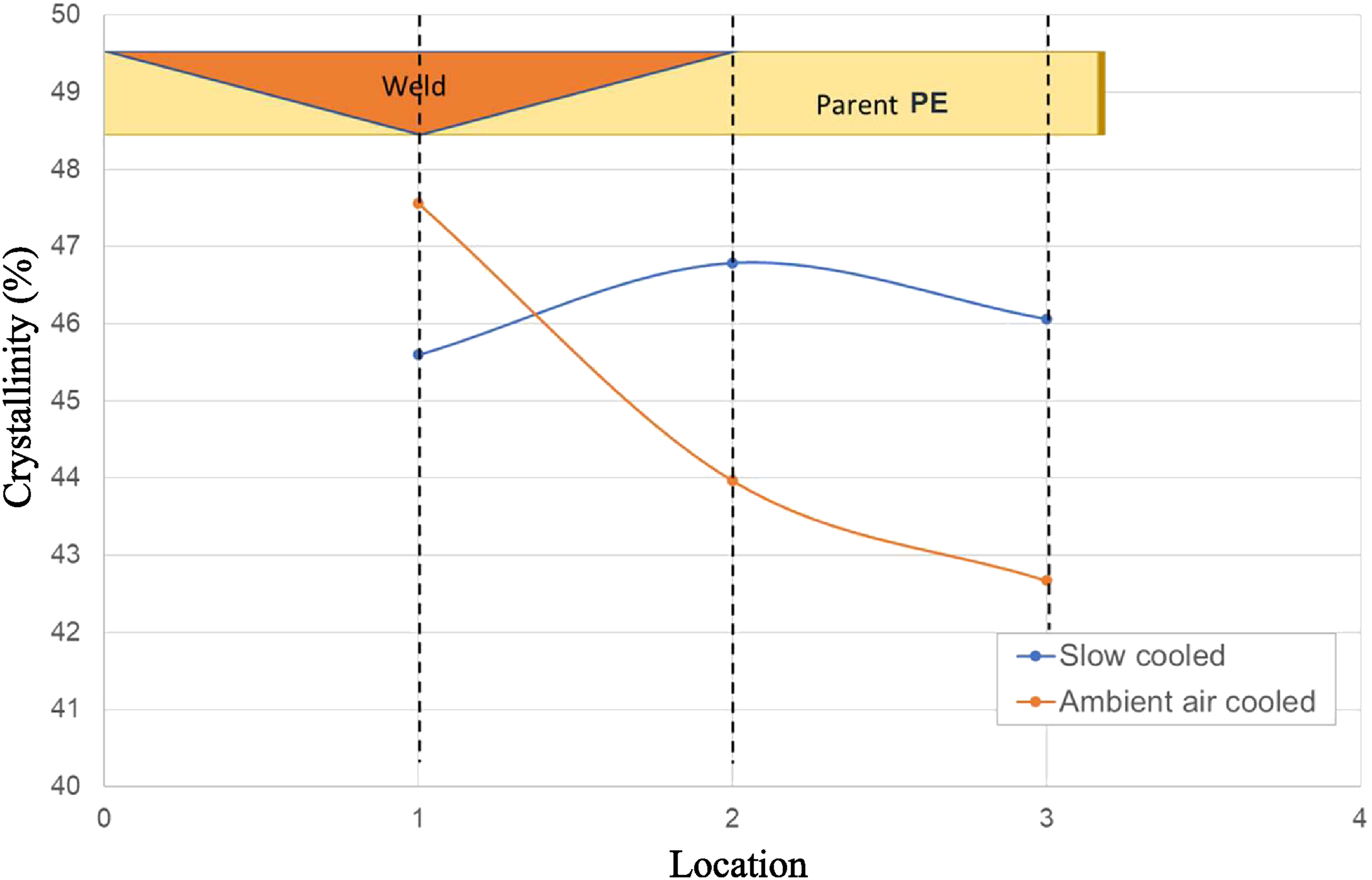
Thus, the cracking observed in the welded region can be attributed to this reduction coupled with the differences in the percentages of crystallinity of the parent material. This reduction in difference would improve mechanochemical since the local stress concentration which exists due to the disparity of the crystalline characteristics of the polymer from the weld to the parent PE is reduced.
Figure 13 presents the microstructure of the welded zone under various welding conditions. In Figure 13(a), a noticeable difference in crystal size between the parent and weld material is evident. However, Figure 13(c) illustrates that by implementing pre-heating and post-cooling, similar crystal sizes will be observed in the microstructure. Microstructure of welded zone: (a) Difference in crystals size in the parent PE material and in weld area; (b) Pre-heated at 60°C; (c) Pre-heated at 60°C and slow cooled.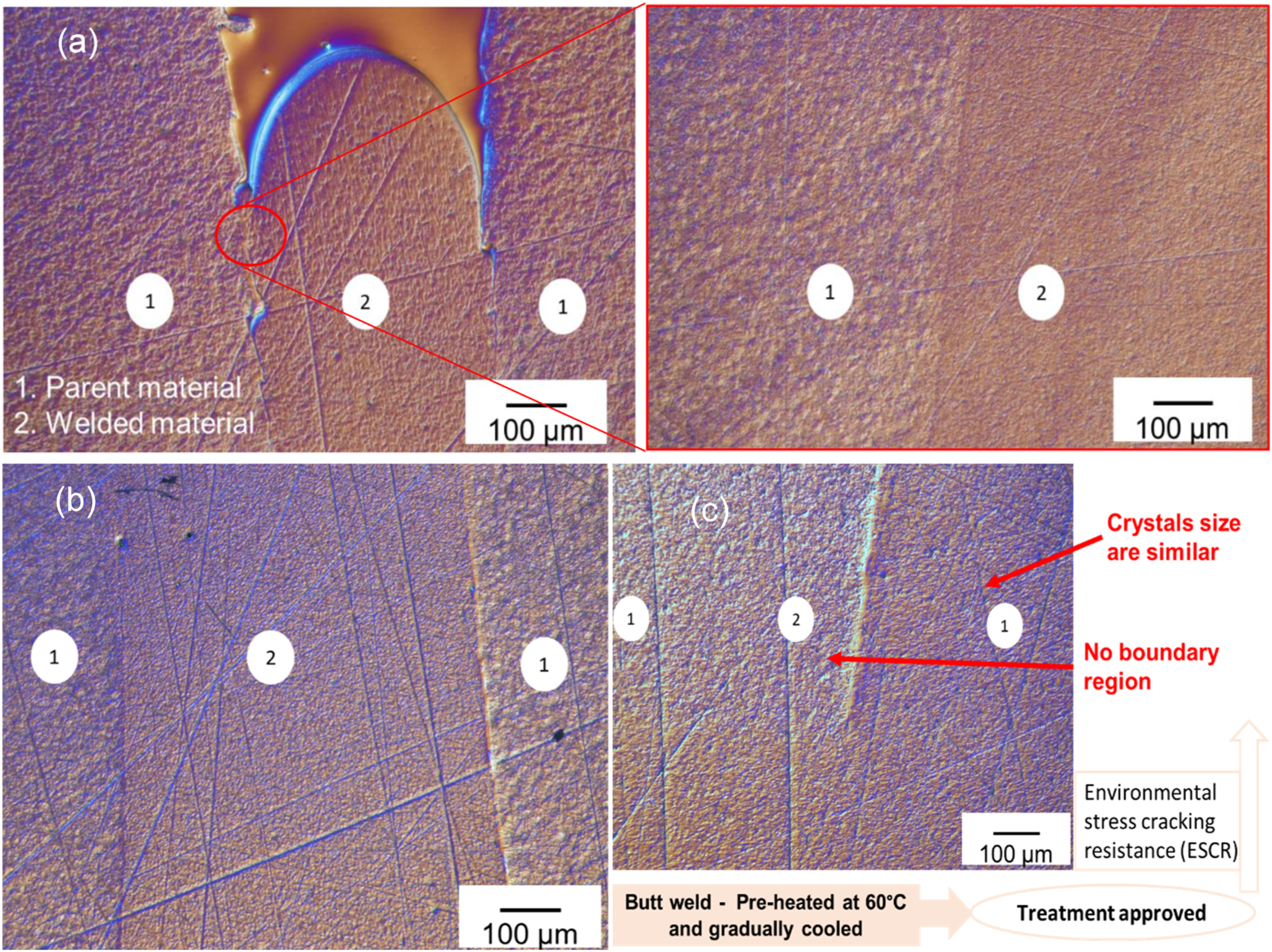
Since DSC can only provide information about the bulk crystallinity, it is necessary to apply a more reliable and accurate method such as SAXS which offers valuable insights into the symmetry, size, degree of crystallinity, and orientation of domains. The information obtained through this analysis is described in the following sections:
SAXS analysis
Influence of pre-heating on degree of crystallinity
The results indicate that crystallinity is influenced by pre-heating. As shown in Figure 14, the crystallinity of the reference material (without any pre-heating and post-cooling conditions) increase as one moves away from the weld region. In contrast, for the pre-heated conditions, the variation in crystallinity is relatively minimal among the all the positions (1, 2, & 3). Furthermore, the influence of pre-heating on crystallinity varies between inner and outer points. This phenomenon is not considerable in the reference sample, suggesting a potential relationship with the heat source’s proximity to the outer points. Among the various pre-heating conditions, a temperature of 60°C exhibits higher and relatively uniform intensity along the weld region. This indicates a higher density of scattering centres or structures with a characteristic size in the sample, similar to the reference sample. Influence of pre-heating on degree of crystallinity.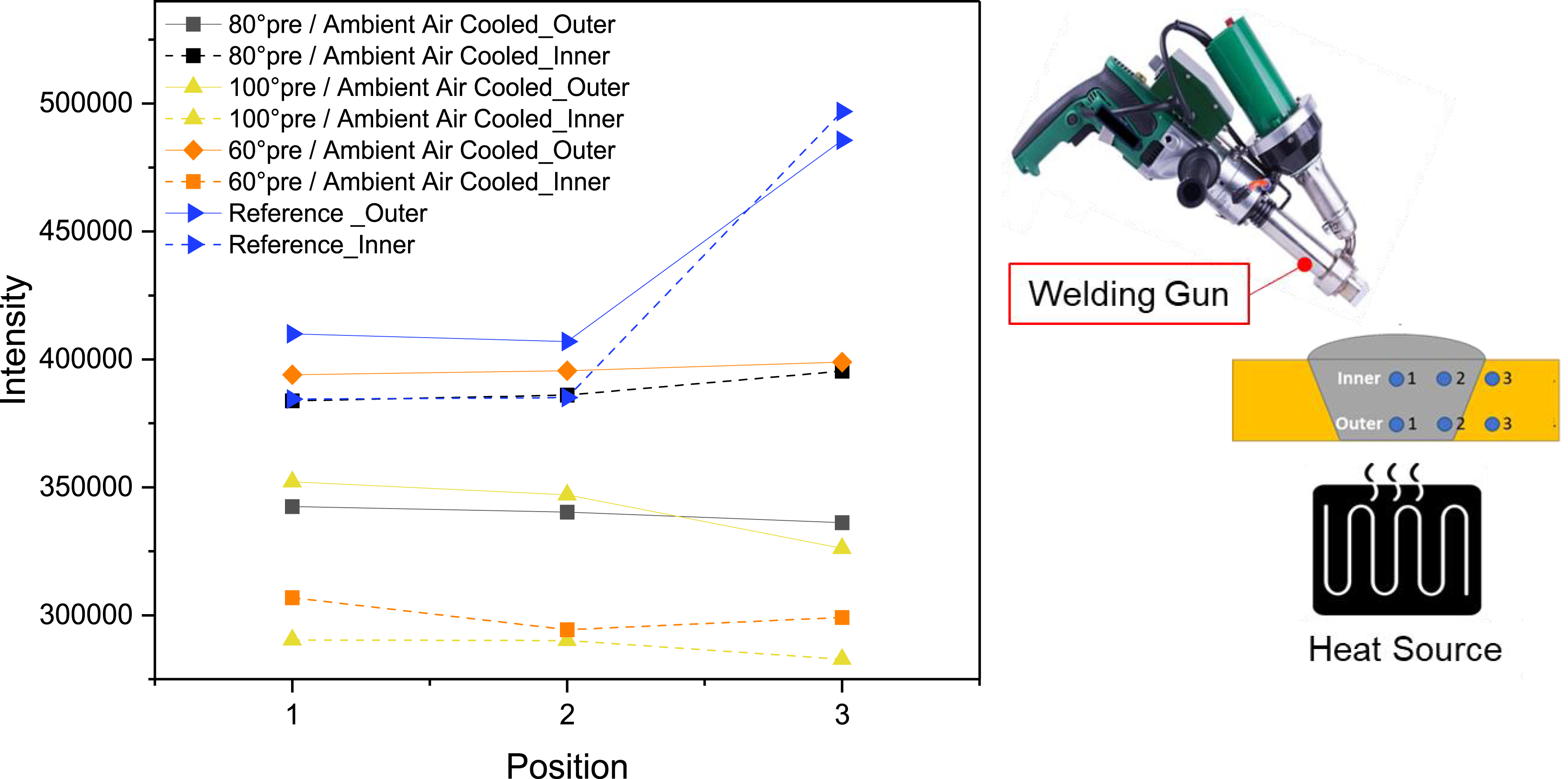
The influence of pre-heating on the peak positions at the inner and outer points is shown in Figure 15. Similarly, variation in the peak positions is relatively minimal among the points located all the positions (1, 2, & 3) compared to the reference sample. Higher peak positions correspond to larger crystal dimensions while lower peak positions signify smaller crystal dimensions. In addition, higher peak position values are observed for both inner and outer points along the weld regions of 60°C pre-heating condition. Influence of pre-heating on the peak-position.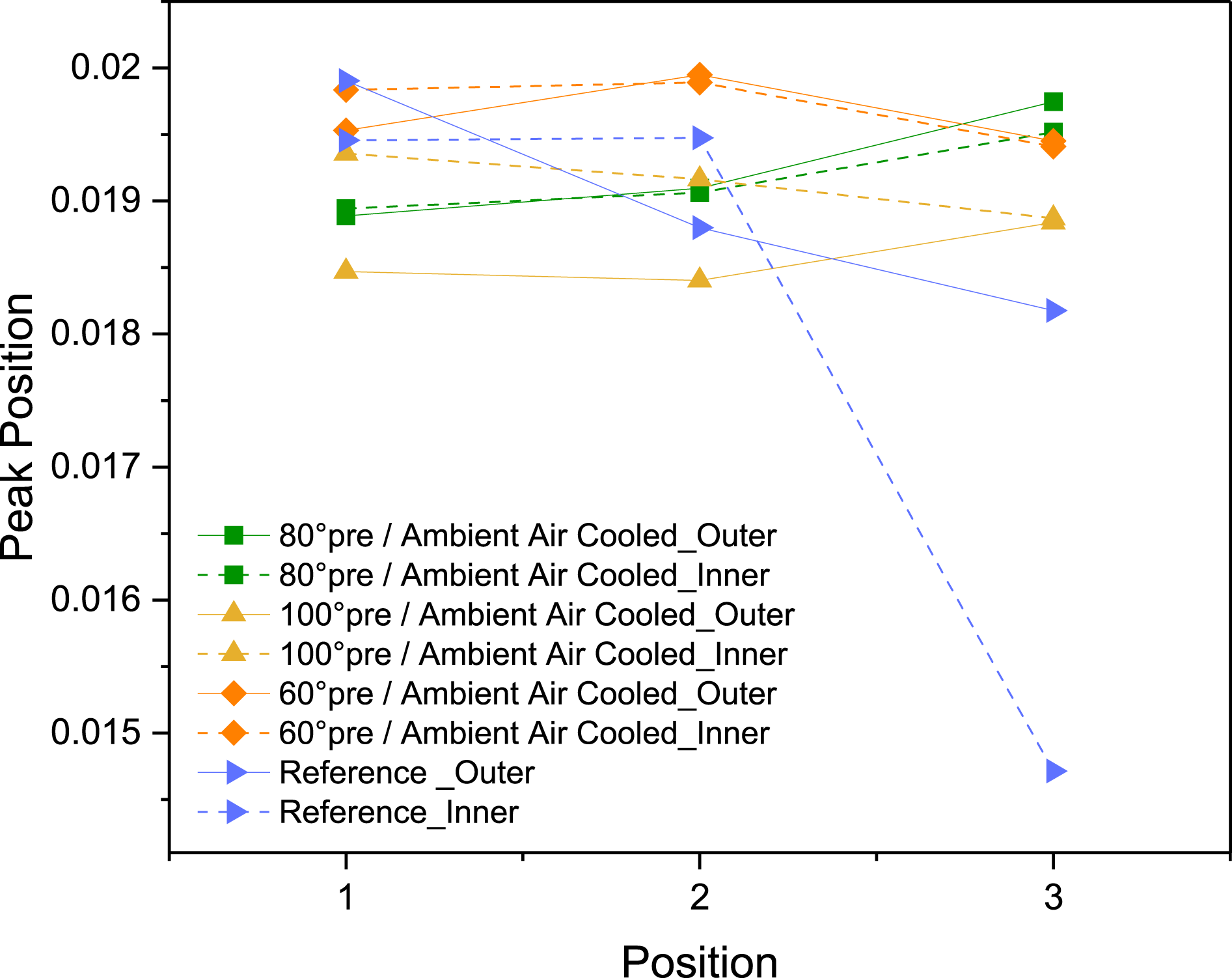
Influence of post-cooling and 60°C pre-heating (inner) on degree of crystallinity
Post-cooling also affects crystallinity. Variation in crystallinity is minimal among the points on the same region compared to those close to the boundary (2 & 3). At high crystallinity the amorphous fraction is small; therefore, crystallites are bound together by a relatively small amount of inter lamellar material. The transition from ordered crystallites to disordered polymer chains causes stress concentration at the intermediate phase resulting in a decrease in environmental stress cracking resistance (ESCR), Figure 16. Influence of post-cooling and pre-heating (60°C) on the degree of crystallinity (Inner points).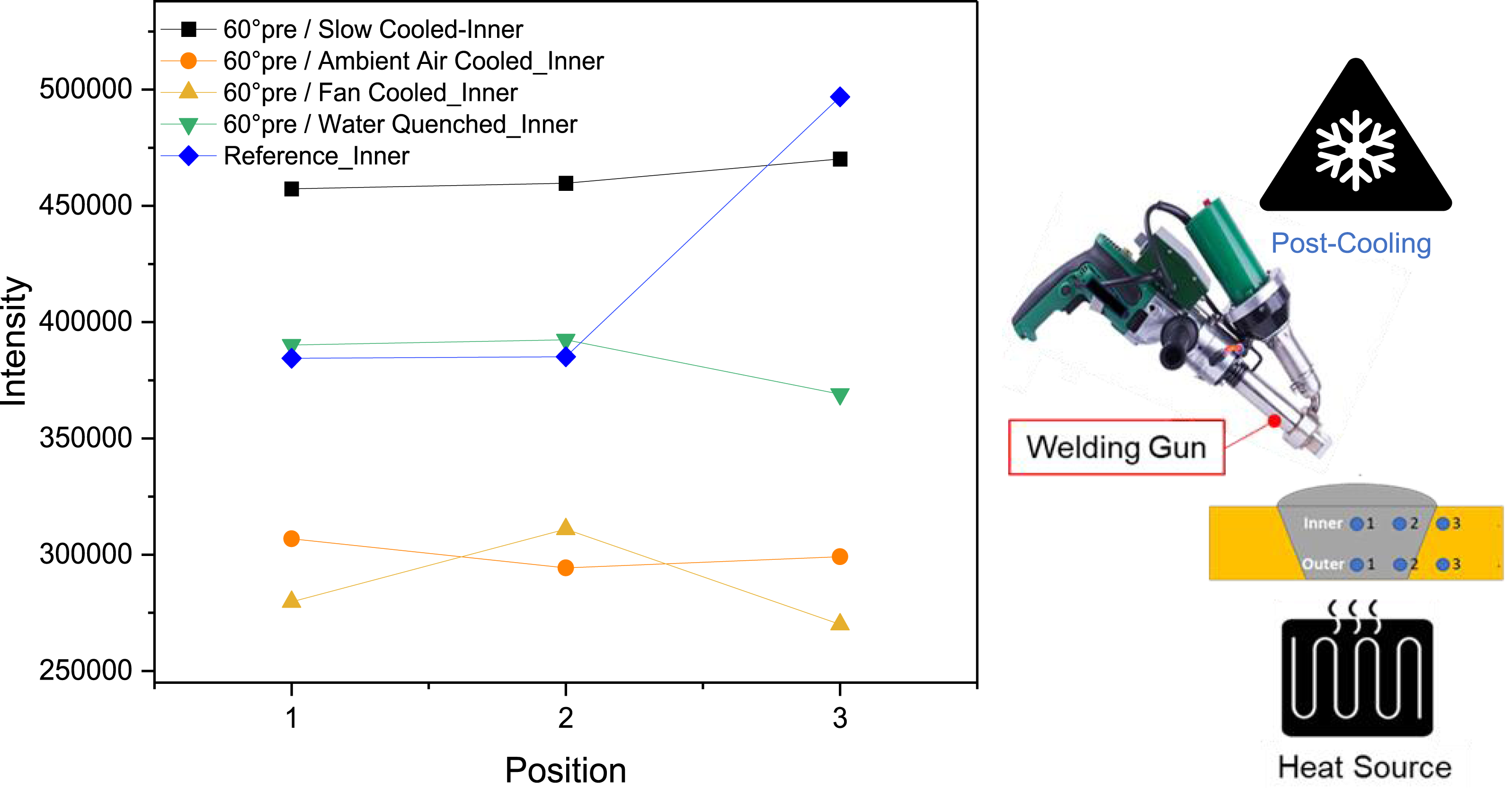
The impact of post-cooling and pre-heating on the peak positions within the inner region is shown in Figure 17(a). It is evident that the variation in peak positions along the weld region (Points 1, 2, & 3) is relatively minimal. The water-cooled sample exhibits a higher peak position, indicating larger crystal dimensions, whereas the slow-cooled sample shows smaller crystal dimensions. The fan-cooled, ambient-cooled, and reference samples generally exhibit similar crystal dimensions (except for point 3) and follow a consistent trend. The impact of post cooling and pre-heating on the peak broadening (width) within the inner region is illustrated in Figure 17(b). Similarly, it can be observed that the variation in peak broadening along the weld region (Points 1, 2, & 3) is relatively minimal. This value for the water-cooled sample is higher indicating smaller crystallite size or higher lattice imperfections, while a narrower peak is observed for the slow-cooled sample that shows larger crystallites and better crystalline quality. Influence of post-cooling and pre-heating (60°C) on the peak position and peak broadening (Inner points).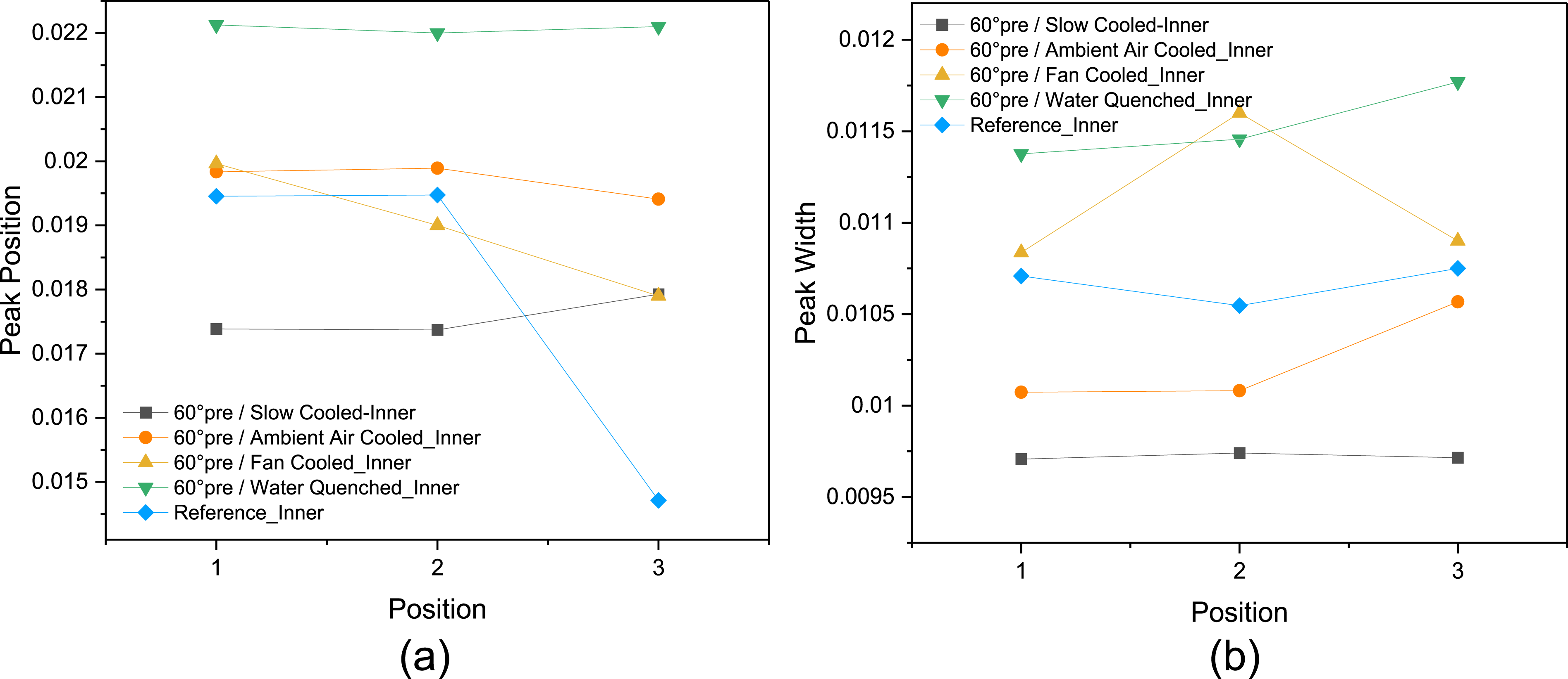
Influence of post-cooling and 60°C pre-heating (outer) on degree of crystallinity
Variation in crystallinity seems to increase moving away from weld region compared to the ambient air-cooled sample.
As discussed earlier, the ESC resistance of PE is closely tied to its crystallinity. Research indicates that a decrease in crystallinity percentage and the presence of thinner lamellar leads to greater intermolecular connections, ultimately enhancing the resistance of PE to cracking. From this experimental result it can be seen that, the slow-cooled condition resulted in the fastest failure in the mechanochemical test (as shown in Figure 21), characterized by the highest crystallinity, Figure 18. When the cooling profile lacks uniformity across the material’s thickness, residual stresses can be anticipated due to thermal gradient. Influence of post-cooling and pre-heating (60°C) on the degree of crystallinity (Outer points).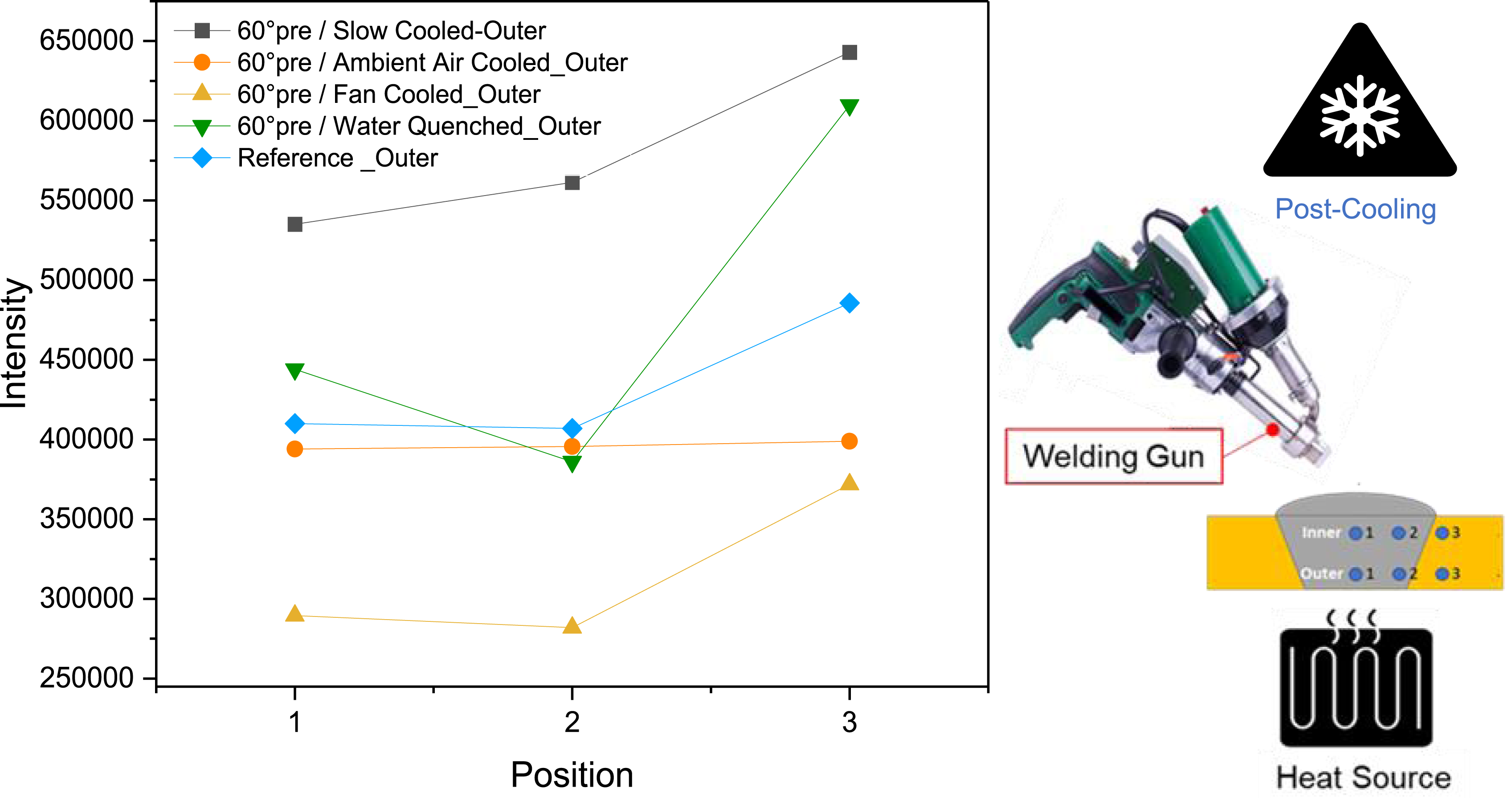
The impact of post-cooling and pre-heating on the peak positions and peak broadening (width) within the outer region is depicted in Figure 19. The water-cooled sample exhibits a higher peak position only at the welding region, indicating larger crystal dimensions, whereas the slow-cooled sample shows smaller crystal dimensions. The fan-cooled, ambient-cooled, and reference samples generally exhibit similar crystal dimensions and follow a consistent trend (Figure 19(a)). Influence of post-cooling and pre-heating (60°C) on the peak position and peak broadening (Outer points).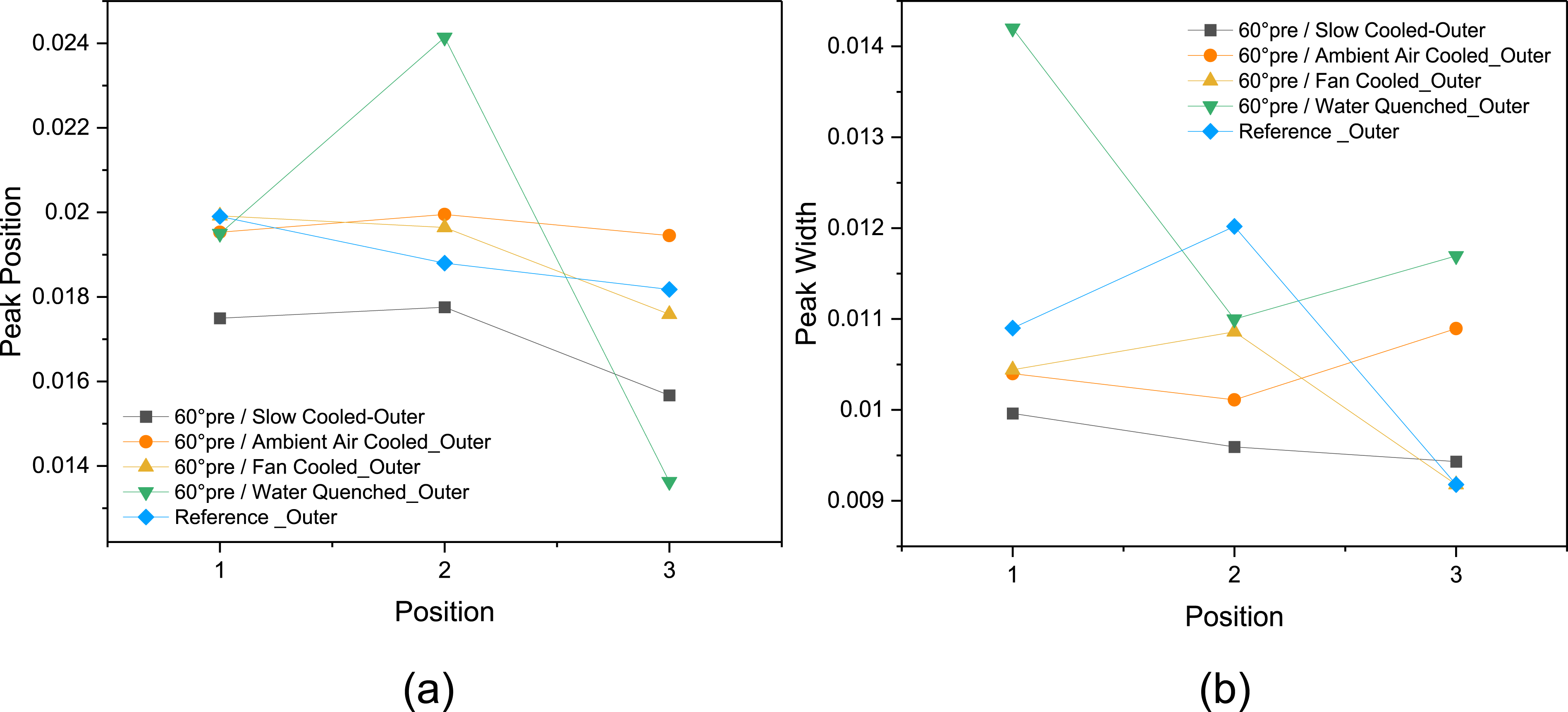
The peak broadening value for the water-cooled sample is higher indicating smaller crystallite size or higher lattice imperfections, while a narrower peak is observed for the slow-cooled sample that shows larger crystallites and better crystalline quality (Figure 19(b)).
Influence of mechanochemical test conditions (immersion in 98% H2SO4) on degree of crystallinity
The mechanochemical test has applications in various fields, primarily for the assessment and characterization of materials. One notable application is environmental stress cracking (ESC), which poses a significant challenge in sectors using plastic materials for containers in packaging. In this study, the examination of crystallinity in welded materials was conducted under various mechanochemical test conditions. For this purpose, the samples immersed in stress crack agent (98% H2SO4) and loaded as described in section 2.2.2.
The results show reduction of crystallinity in the sample immersed in stress crack agent (98% H2SO4). Interesting to note that this reduction in the outer region is a uniform across the points, Figure 20. This brings about the question of whether the mechanochemical test is reducing crystallinity or something else is happening. The mechanochemical test results may indicate that the stress crack agent accelerates brittle failure of the loaded polymer by penetrating the amorphous regions and plasticizing them. Plasticization promotes chain untangling in the amorphous areas and ‘lubricates’ the tie molecules. Tie molecule ‘pull-out’ is thereby assisted, resulting in brittle failure earlier and at lower stresses than expected. Variations in crystallinity from the weld point to the parent material are reduced for the inner portion. One possible explanation for this observation could be that the specimens exhibit slight curvature, resulting in a varied loading scenario, Figures 20 and 21. Influence of mechanochemical test condition on degree of crystallinity. Mechanochemical test results.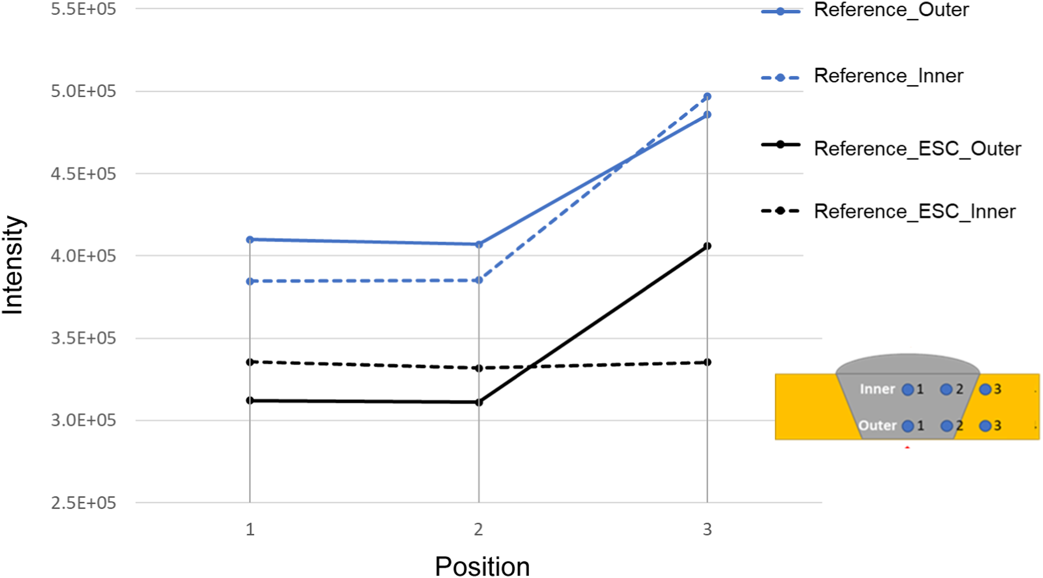
Conclusion
In this study, a dependable method is employed to weld clean PE panels under various pre-heating and post-cooling conditions. SAXS is utilized to examine and assess how the welding process affects the crystallinity of the materials in the welded zone compared to the parent materials. The findings obtained from this study are summarized as below: • Mechanical strength analysis: The samples pre-heated at 60°C and 80°C with an ambient air-cooling rate of ≤16°C/min showed higher strength compared to the sample pre-heated at 100°C. While the water-cooled samples had the lowest strength. The same trend was observed for elongation to failure. • Microscopic analysis: DSC analysis confirmed that controlling cooling can reduce the variation in crystallinity in the weld and heat-affected zone. Pre-heating affected crystallinity, with the influence varying between inner and outer points due to the heat source’s proximity to the outer points. Variation in crystallinity increased up to 60°C pre-heating temperature and then decreased gradually. Crystallinity variation was relatively minimal among points within or close to the weld region compared to those away from the weld region. • The high crystallinity led to stress concentration at the intermediate phase, resulting in a decrease in ESCR. Crystallinity variations from the weld point to the parent material were reduced in the inner portion, possibly due to slight specimen curvature leading to a varied loading scenario. • In the SAXS analysis, pre-heating resulted in a reduction of crystallinity variation among the points located in or close to the weld region compared to the reference sample. Additionally, the influence of pre-heating on crystallinity varied between the inner and outer portions due to the location of the heat source. Moreover, post-cooling resulted in a reduction in the variation in crystallinity of the points that were away from the weld region compared to the reference sample.
Footnotes
Acknowledgments
The authors would like to acknowledge the following funding: ARC LIEF: Australasian facility for the automated fabrication of high-performance bespoke components (LE140100082).
ARC ITTC: ARC Training Centre for Automated Manufacture of Advanced Composites (IC160100040).
The authors also wish to acknowledge: Access to the SAXS facility at the Australia Centre for Neutron Scattering (ACNS) was supported through an ANSTO beamtime award (P6850).
The substantial assistance and backing offered by Dr Chris Garvey from ACNS, ANSTO in the initial stages of this project.
Credit author statement
Declaration of conflicting interests
The author(s) declared no potential conflicts of interest with respect to the research, authorship, and/or publication of this article.
Funding
The author(s) disclosed receipt of the following financial support for the research, authorship, and/or publication of this article: This work was supported by the ARC LIEF: Australasian facility for the automated fabrication of high-performance bespoke components (LE140100082), ARC ITTC: ARC Training Centre for Automated Manufacture of Advanced Composites (IC160100040), Access to the SAXS facility at the Australia Centre for Neutron Scattering (ACNS) was supported through an ANSTO beamtime award (P6850).
Data Availability Statement
The data that support the findings of this study are available from the corresponding author upon reasonable request.