
Abstract
Fiber reinforced multiscale composites represent a cutting-edge class of advanced materials that have garnered significant attention in the realm of materials science and engineering. These advanced materials intertwine various fiber reinforcements, meticulously tailored at micro, to macro levels, imparting them with remarkable mechanical, thermal, and functional properties. In this research, an experimental investigation was performed to observe the tensile fatigue behavior of short and continuous carbon fiber reinforced additively manufactured multiscale thermoplastic composites. The multiscale composite was fabricated by combining layers of continuous woven carbon fiber (CCF) with short carbon fiber (SCF) reinforced acrylonitrile butadiene styrene (ABS) laminates which were additively manufactured using the fused filament fabrication technique. It was observed that the multiscale composite exhibits a maximum 127% higher strength and 154% higher Young’s modulus than neat ABS polymer. Based on non-normalized stress-life curves, multiscale composites with four layers of CCF have a higher fatigue strength than multiscale composites with one layer of CCF. However, when the applied stress is normalized by the quasi-static strength, the multiscale composite with one layer of CCF had a longer fatigue life than the four layers of CCF reinforced multiscale composites at high normalized cyclic stress, while the multiscale composite with four layers of CCF exhibited a longer fatigue life at low normalized cyclic stress. The four CCF layers reinforced multiscale composites experienced a different extent of fiber pull-out, matrix cracking, and delamination at different stress levels. Conversely, fatigue failure of the one layer of CCF reinforced multiscale composites primarily occurred due to localized fiber breakage with minimal matrix-related damage.
Introduction
Laminated fiber reinforced thermoplastic composites are widely used in industries like aerospace, automotive, and medical due to their exceptional combination of high strength, stiffness, and durability, with lightweight design flexibility.1,2 The heterogeneous nature of fiber reinforced composites and the presence of defects such as voids, delamination, and weak fiber/matrix bonding, make them susceptible to fatigue failure. 3 Carbon fiber composite, which boasts high strength and stiffness, exhibits superior fatigue behavior compared to other fiber reinforced composites. 4 In recent times, additive manufacturing, also known as 3D printing, has gained popularity for fabricating carbon fiber reinforced thermoplastic composites as it offers the ability to build complex shapes at a lower cost.5,6 Fused filament fabrication (FFF) is the most popular and reliable additive manufacturing technique for fabricating additively manufactured carbon fiber composites. 7 There has been a significant increase in the application of fused filament fabricated parts made of neat polymers, leading to a considerable amount of research conducted to understand the fatigue behavior of these materials. Afrose et al. 8 examined how the raster orientation affected the tensile fatigue of FFF polylactic acid (PLA). They observed that PLA with a 45° off-axis raster orientation demonstrated a longer fatigue life than other orientations, despite being subjected to the same stress level. Fischer et al. 9 investigated the impact of building orientation on the fatigue properties of fused filament fabricated Ultem 9085 by using dog bone-shaped tensile specimens to characterize tensile fatigue behavior. They found that the fatigue life of Ultem 9085 was influenced by the building orientation at higher load levels, while it remained unaffected at lower loads. The influence of FFF process parameters (layer height, fill density, nozzle diameter, and velocity) on the fatigue performance of PLA was explored by Gras et al. 10 They observed that fatigue performance is improved with the increase of layer height, fill density, and nozzle diameter with a minimal change in fatigue performance observed with the change of printing velocity. Forcada et al. 11 studied the effect of build orientation on the flexural fatigue properties of FFF polycarbonate (PC). They observed that the YZ build orientation had longer lifetime compared to the XY and XZ directions. They also developed an isotropic FEA model to establish a correlation with the experimental data. They validated the FEA model to predict the fatigue failure of FFF parts.
Although there are several studies on the fatigue behavior of neat thermoplastic polymers made by FFF, research on fiber reinforced FFF thermoplastic composites is very limited. Imeri et al. 12 first investigated the tension-tension fatigue properties of continuous fiber reinforced polymer composites. Carbon fiber, glass fiber, and Kevlar-reinforced fused filament fabricated polymer composites with different fiber orientations and infill types were considered for the experiments. Their results indicated that isotropic infill carbon fiber with zero and one ring orientation has a higher resistance to failure under fatigue loading. Pertuz et al. 13 also performed a similar type of quasi-static and fatigue study of continuous glass, Kevlar, and carbon fiber reinforced nylon FFF composites. They fabricated the composites with three different fiber orientations of 0o, 45o, and 60° and found that the 0° carbon fiber composite exhibited the best fatigue response.
Recently, multiscale composites have gained increased attention due to the synergistic effect of different scales of reinforcement, which allows tailoring the mechanical properties at different length scales by controlling the size and orientations of the fiber. 14 The manufacturing of multiscale composites using additive manufacturing techniques is relatively new. The only study reported on the fatigue behavior of additively manufactured multiscale composites was done by Ahmadifar et al., 15 in which the bending-bending fatigue behavior of a continuous glass fiber and short carbon fiber (SCF) reinforced PA6 (ONYX) composite was explored. The composite was fabricated by a Markforged printer, which used a separate nozzle to embed pre-impregnated tows of glass fibers. They found that, at the same maximum strain, the SCF- PA6 composite exhibited a higher number of cycles to failure than the continuous glass fiber reinforced CF-PA6 composite. Based on the literature, it is apparent that few of the previous studies on the fatigue of additively manufactured polymers and composites have focused on multiscale reinforcements. Furthermore, the incorporation of woven continuous fibers into additively manufacturing processes has not been investigated at all. In the current investigation, a novel manufacturing technique was developed for fabricating a multiscale composite by inserting woven continuous carbon fiber (CCF) layers between additively manufactured SCF reinforced thermoplastic ABS layers. An experimental investigation is conducted to observe the tensile fatigue behavior of this novel multiscale composite, assessing its potential for cyclic load-bearing applications. Furthermore, morphological and microscopic analyses were also carried out to identify possible failure mechanisms at both the microscopic and macroscopic levels.
Materials and composite fabrication
The multiscale composite was fabricated by embedding either one or four layers of plain-woven carbon fabric between layers of SCF reinforced acrylonitrile butadiene styrene (ABS) printed by the FFF method. The 203 g/m2 balanced fabric, named F-2046, was obtained from Composite Envisions (Wausau, WI, USA), and consisted of standard T300-3K tows from Toray (Decatur, AL, USA). The fiber specifications are given in the Supplemental Information. The FFF composite feedstock, obtained from 3Dxtech (Grand Rapids, MI, USA) had a 1.75 mm diameter and contained 15 wt% short carbon fibers. For comparisons of quasi-static tensile properties, specimens were FFF printed using SCF reinforced ABS feedstock without any carbon fabric layers and also using neat ABS feedstock without any carbon fabric layers.
In a fiber reinforced composite, fiber-matrix bonding has a large influence on the mechanical properties.
16
Thorough impregnation promotes superior bonding strength between fibers and thermoplastic matrix.16,17 Therefore, sheets of woven carbon fabric were pre-impregnated with neat ABS prior to their embedment into the multiscale composite. To prepare ABS for impregnation into the carbon fabric, 10 g of ABS pellets obtained from Filastruder (Atlanta, GA, USA) were dissolved into 30 g (50 mL) of acetone. The mixture was stored overnight in an airtight jar to ensure the ABS was properly dissolved, after which it was stirred at 2500 rpm for at least 2 h for homogenization. A sheet of woven carbon fiber was placed into a rigid frame, dipped into the ABS solution for 5 minutes, and pulled out slowly to allow the excess solution to drip off from the carbon fiber sheet. The thin ABS-impregnated carbon fabric was dried for 24 h at room temperature, removed from the frame, and cut to the size needed for embedment into specimens. A schematic outline of the fabric pre-impregnation process is shown in Figure 1(a). Schematic of (a) Pre-impregnation of woven carbon fabric (b) Composite fabrication process.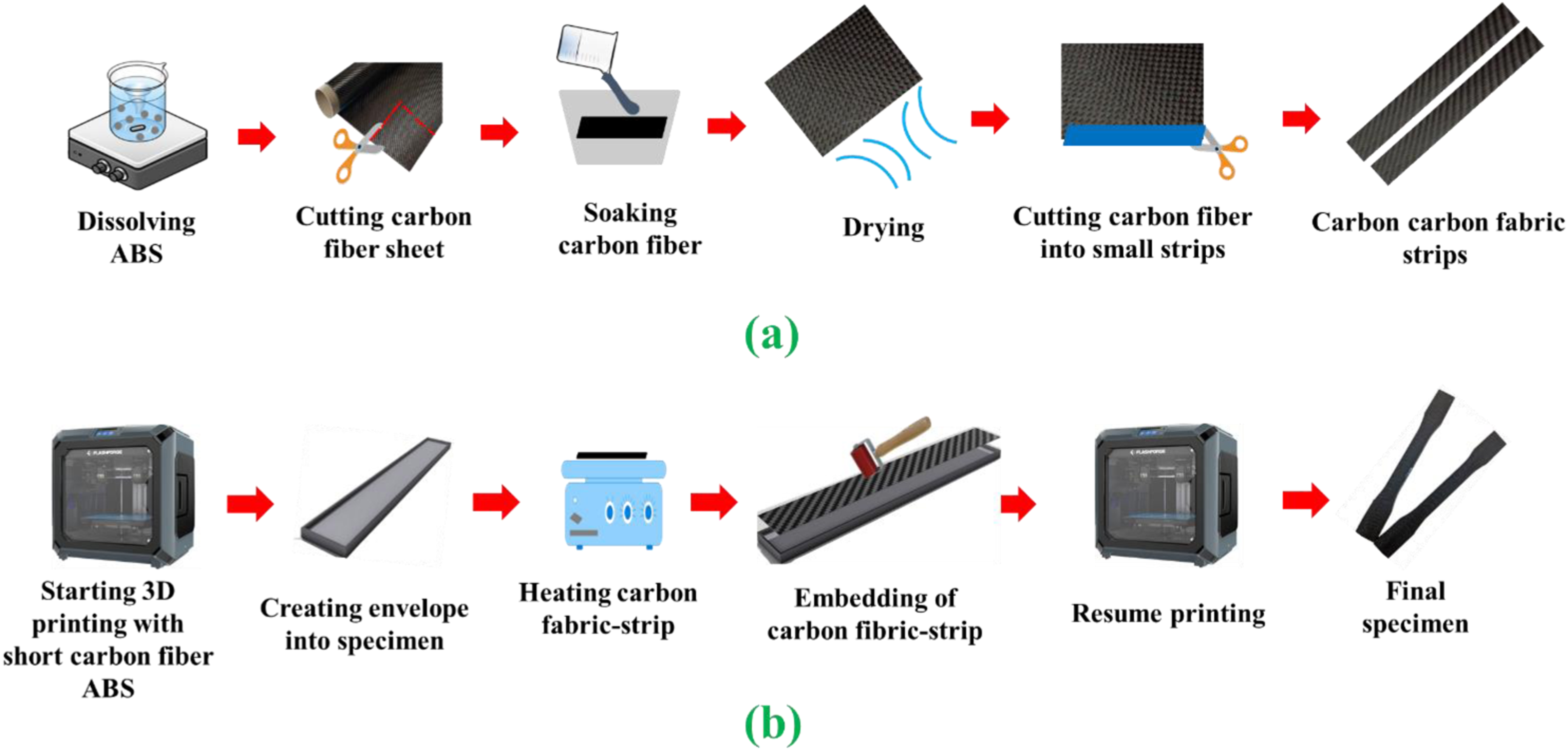
Process parameters used for printing multiscale composite.
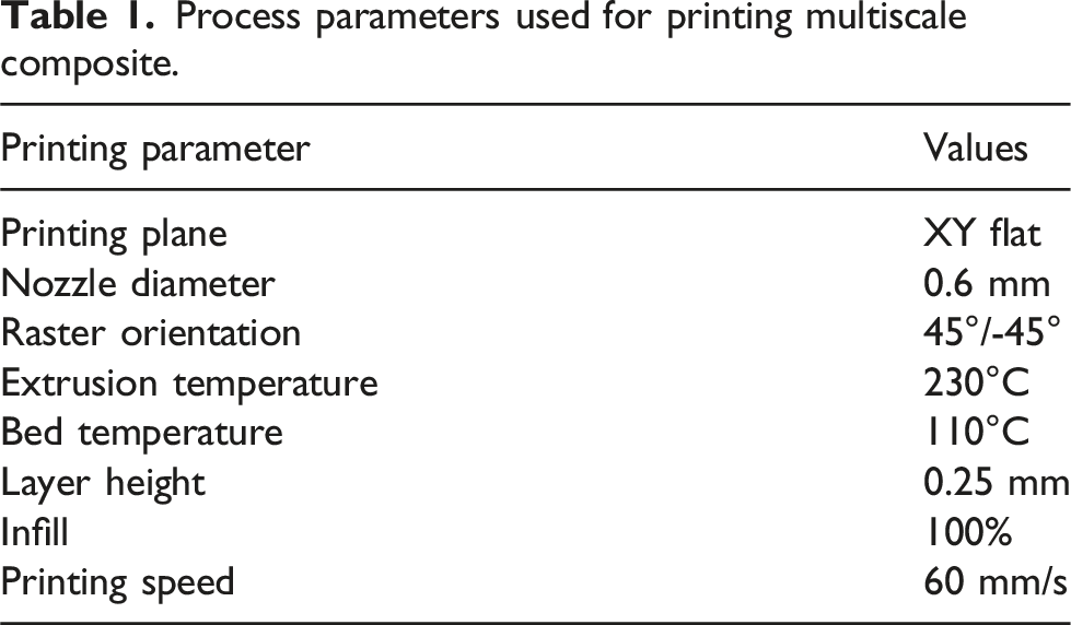
The multiscale composite was fabricated by embedding 0°/90° oriented woven carbon fiber fabrics between the short carbon fiber reinforced polymer matrix. To embed the continuous carbon fiber, an envelope was sketched into the three-dimensional model of the specimens in Solidworks, as shown in cross-section in Figure 2. The length and width of the envelope are 1 mm smaller than the overall specimen dimensions. The dimensions of the envelope for tensile specimens are 163 mm in length and 11 mm in width, while for fatigue specimens, the dimensions are 175 mm in length and 23 mm in width. The average thickness of the ABS-impregnated fabric was measured as 0.35 mm. For the specimen with one fabric layer, a hollow rectangular envelope with 0.4 mm depth was printed into the middle of the specimen to create space for the fabric with minimal air gaps. A pre-programmed printing pause was included at the layer of the envelope. The continuous carbon fiber strip was preheated for 5 minutes at 200°C before embedding, which allowed the ABS in the carbon fiber strip to reach a semi-molten phase that promotes adhesion between the embedded carbon fiber and the remaining parts of the specimen. Once the heated fabric was manually embedded in the envelope, it was consolidated using a hand roller and printing was allowed to continue. Figure 1(b) shows a schematic of the fabrication process. A similar procedure was followed to fabricate the four layers of continuous carbon fiber reinforced multiscale composite where equally placed envelopes were modeled as shown in Figure 2. Table 2 shows the constituent percentages of different composites made in this study, which were calculated as shown in the Supplemental Information using constituent masses and densities and the overall specimen volume by immersion testing. Pure ABS and short carbon fiber reinforced composites, for quasi-static testing only, were fabricated by following the conventional fused filament fabrication process. Schematic of cross-sectional view of continuous carbon fiber distribution inside of the composite. Weight and volume fractions of constituents of composites. The carbon contents include continuous fibers in fabrics and short fibers in the carbon/ABS feedstock.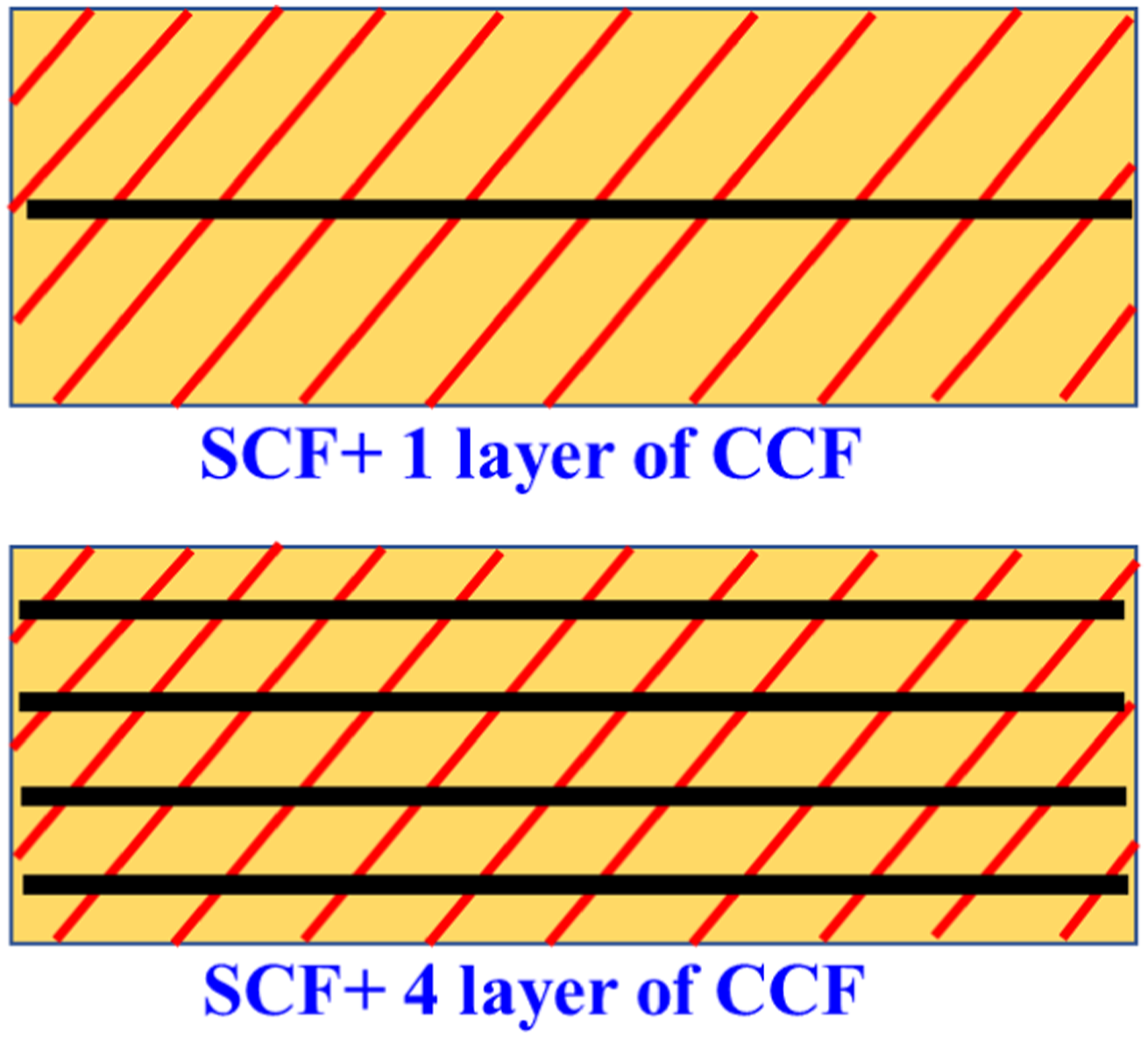
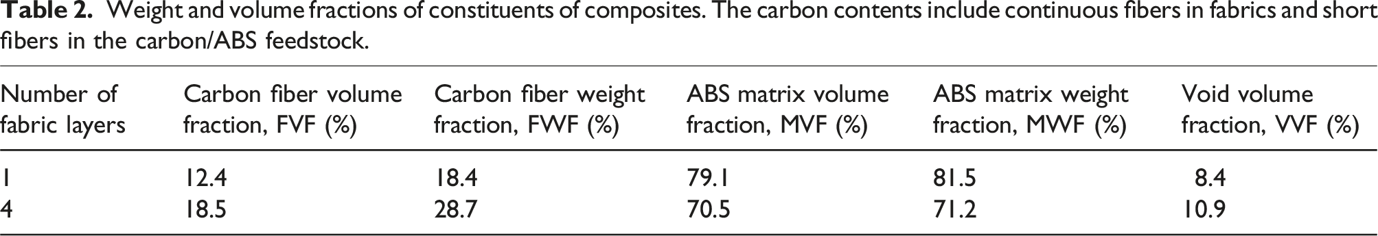
Figure 3 shows optical microscope images of transverse cross-sections of the one- and four-layer CCF reinforced multiscale composites. The majority of the voids are in and around the CCFs. These voids were formed during preparation of the individual fabric layers and during printing of SCF-reinforced filament over the fabrics. The filling of micron-scale roughness on the surface of fabrics with highly viscous SCF-reinforced extrudate can be challenging.
18
Besides these voids near the CCF fabrics, triangular-shaped inter-bead voids (highlighted by the dashed circles) and randomly distributed irregular-shaped voids can be seen in the SCF regions, as is typically seen in FFF-printed materials.
19
Cross sectional microscopic view of (a) SC + 1CCF and (b) SC + 4CCF multiscale composite.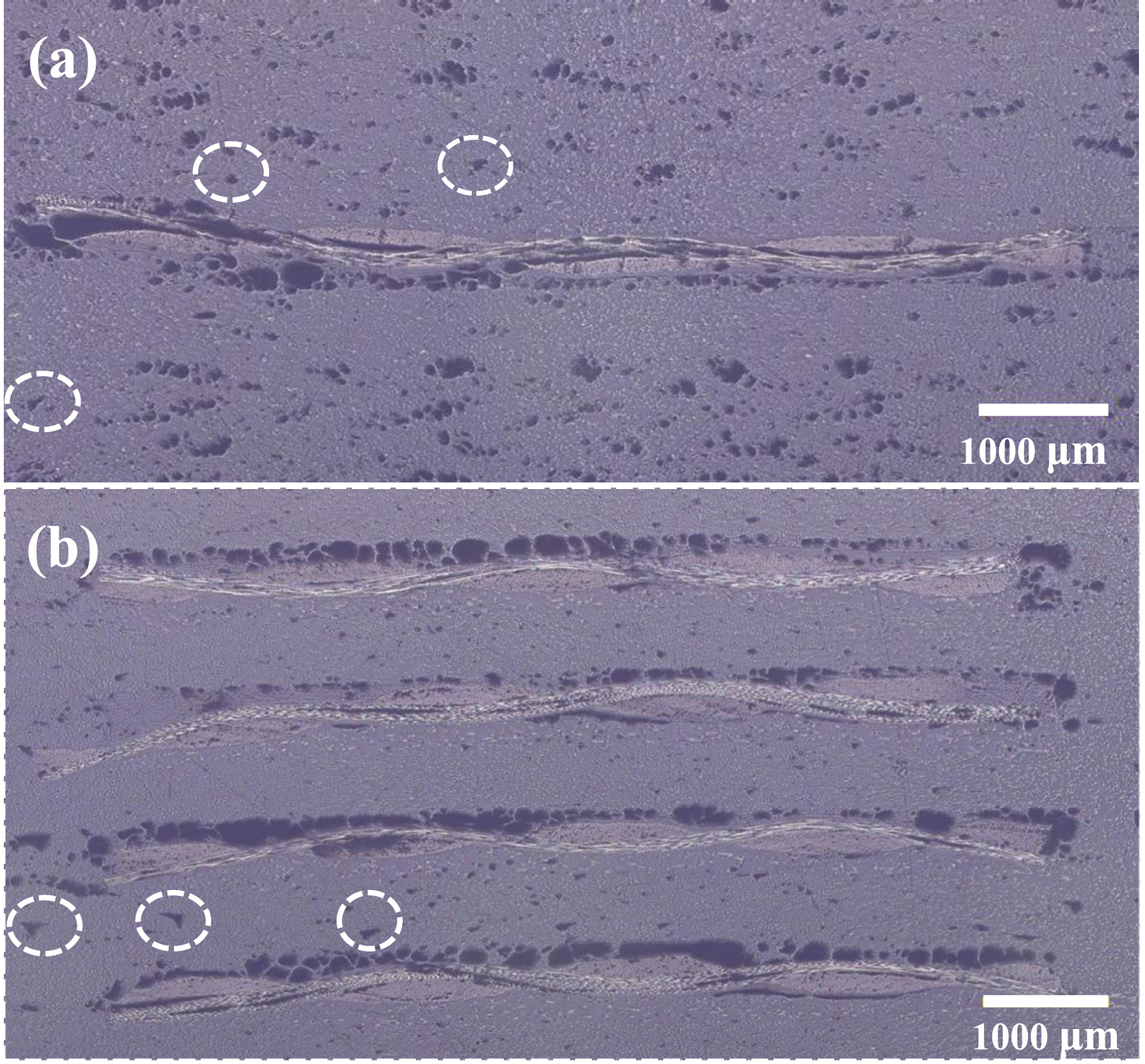
Experimental details
Quasi-static tensile characterization
Quasi-static tensile tests were conducted with a screw-driven load frame ( Schematic of (a) tensile specimen (b) fatigue specimen. Red dashed lines show the envelope for woven fabric.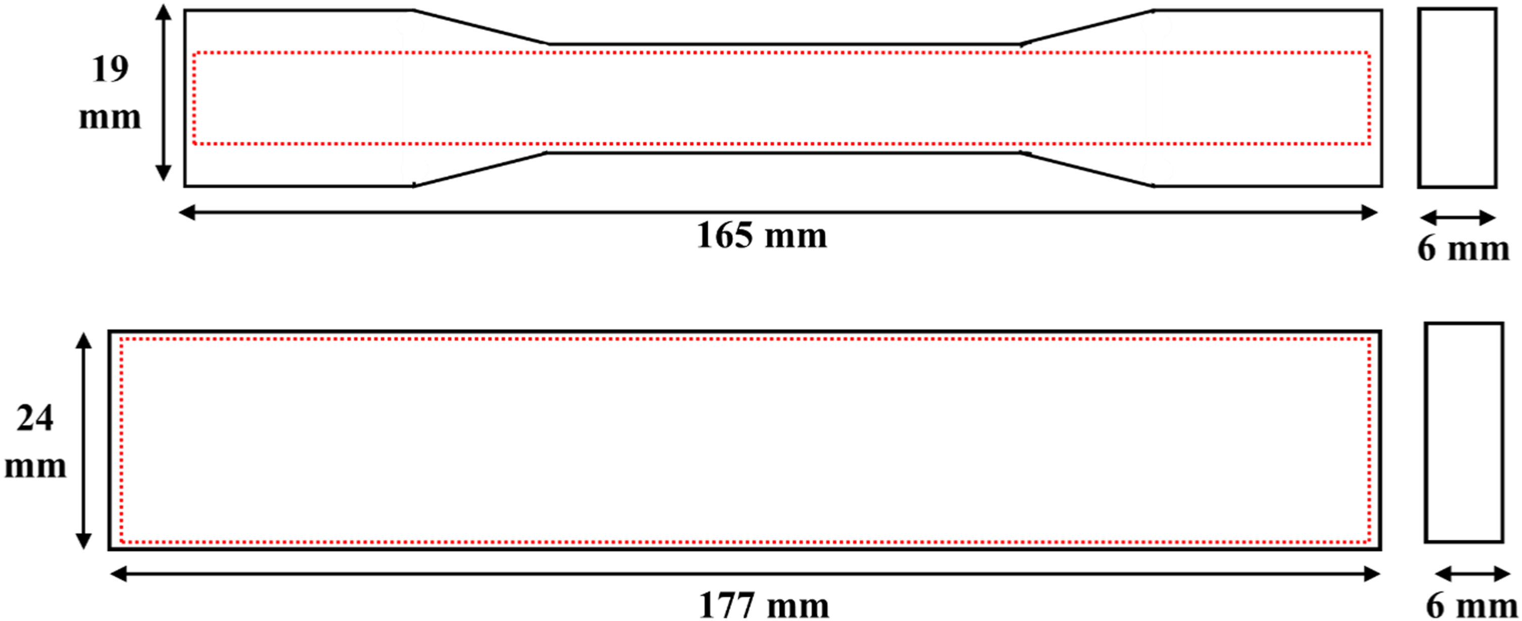
Tension-tension fatigue characterization
For tensile fatigue testing, rectangular 177 mm × 24 mm rectangular specimens with 6 mm thickness as shown in Figure 4(b) were used. Previously, it was observed that during fatigue testing, dog bone specimens were prone to failure in the fillet transition.
4
To avoid this and ensure consistent failure in the gage section, straight-sided specimens were deliberately chosen for fatigue testing. The quasi-static strength of the straight-sided fatigue specimens was verified to be similar to that of the dog bone specimens (within one standard deviation). A servo-hydraulic load frame (
Digital image correlation analysis
In this study, a two-dimensional digital image correlation (DIC) system was used to measure the strain. To prepare the specimen for DIC, at first, a thin layer of white spray paint was manually applied on the surface of the specimens and allowed to dry. After drying, flat black paint was sprayed on the white surface to create a fine, high-contrast, and random speckle pattern as shown in Figure 5(a). A 5 MP Allied Vision machine vision camera equipped with a 75-mm fixed focal length lens operating at a resolution of 2464 × 2056 pixels was used to capture the images for DIC. A LED panel light was used to ensure uniform illumination of the specimen in the region of interest. The experimental setup is shown in Figure 5(b). To synchronize the strain data with the load values, the image capturing rate (10 fps) and mechanical data acquisition rate (10 Hz) were kept the same. After finishing the test, images were imported into Aramis correlated software to run the correlation. By following the correlation algorithm described in the literature,
22
the DIC software locates a subset in the image taken at an undeformed state and compares it with its corresponding subset in an image taken at a deformed state. The subset size is the width and height of the subset square which governs the spatial resolution of the displacement measurement within the region of interest.22,23 Due to the differing specimen dimensions in the tensile testing and fatigue testing, two distinct regions of interest (ROI) were chosen for the DIC analysis. The size of the ROI for the tensile test was 13 mm × 50 mm, while for the fatigue test, it was 24 mm × 120 mm. The step size is another important factor in the correlation process. Step size defines the value of overlapping subsets and tracking during the correlation process.
23
Ideally, the ratio of the subset to step needs to be between 3 and 4. For this analysis, a subset size of 21 pixels is used and the step size is 5 pixels. By utilizing these parameters, the average strain of the region of interest (ROI) was calculated. (a) A typical speckle pattern for DIC (b) Experimental setup.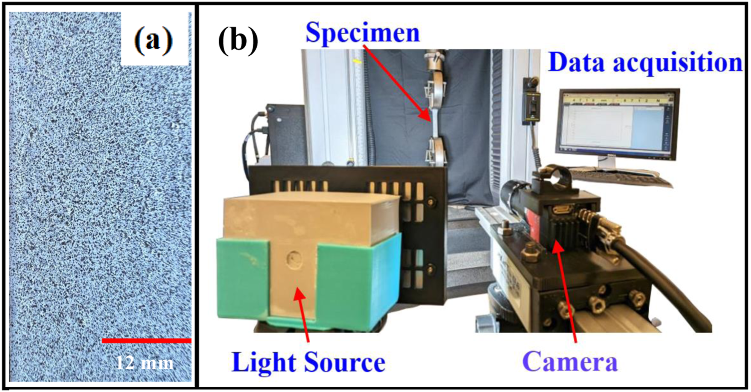
Results and discussion
Quasi-static strength and modulus
The characteristic stress–strain responses of the fused filament fabricated neat ABS, short carbon fiber (SCF), and both multiscale composites (SCF+1CCF, SCF+4CCF) are shown in Figure 6(a). The curves are representative of a minimum of five experiments for each category. Ultimate tensile strength, Young’s modulus, and failure strain of the composites were obtained from these stress–strain responses and are compiled in Figures 6(b)–(d). Multiscale composites show enhanced tensile strength as compared to neat ABS specimens and short carbon fiber reinforced specimens. One layer of continuous carbon fiber reinforced (SCF+1CCF) multiscale composite shows 28% higher tensile stress as compared to pure ABS. A significant improvement in ultimate tensile stress is observed in four-layer continuous carbon fiber reinforced (SCF+4CCF) multiscale composite. The addition of four layers of continuous carbon fiber increases the tensile strength of the multiscale composite to 75.5 MPa as shown in Figure 6(b) which is 114%, and 76% higher as compared to short carbon fiber and one-layer reinforced multiscale composite, respectively. (a) Tensile stress–strain diagrams; (b) ultimate strength (c) Young’s modulus, and (d) failure strain of the investigated materials.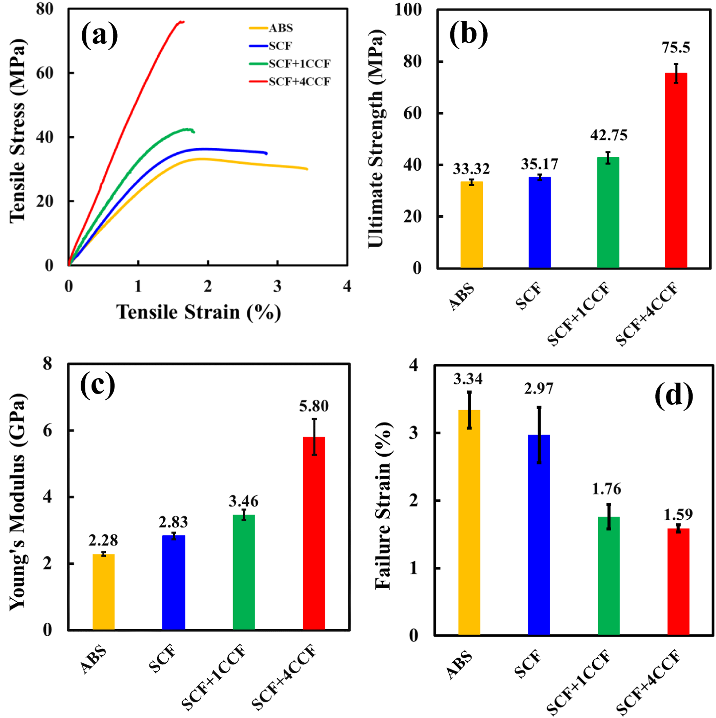
Similar to tensile strength, multiscale composites also have a superior Young’s modulus compared to neat ABS and SCF composites as shown in Figure 6(c). Young’s modulus of SCF+1CCF composite is 3.46 GPa which is 51% higher than neat ABS. The SCF+1CCF multiscale composite shows the highest improvement of Young’s modulus versus the neat ABS and SCF: 154% and 105%, respectively. Though multiscale composites show enhanced tensile strength and Young’s modulus, the failure strain of the multiscale composites as shown in Figure 6(d) is substantially lower than the neat ABS and short fiber reinforced materials. The multiscale composites with short and continuous fibers show 47%–52% lower failure strain as compared to the neat ABS. Carbon fiber has higher strength as well as higher modulus as compared to the ABS matrix. The addition of the continuous fiber effectively transferred the applied load to the highly stiff continuous carbon fiber resulting in carbon fibers carrying most of the applied load. 24 As a result, the load-carrying capacity and the Young’s modulus of the material improved. In addition to that, the mechanical properties of the fiber-reinforced composites depend on the wt% of the fiber. Since fiber has higher mechanical strength and modulus than polymer matrix, a higher amount of carbon fiber in composite provides higher strength and modulus. On the other hand, the lower failure strain of carbon fiber as compared to the ABS matrix causes a reduction in failure strain after embedding of continuous carbon fiber. 24
S-N curves
Figure 7 shows the S-N curves of multiscale composites with one and four layers of continuous carbon fiber. Since the ultimate tensile strength of the SCF+1CCF and SCF+4CCF composites are different, fatigue tests were conducted at the different stress levels of 90%–30% of their ultimate tensile strength. For each stress level, a minimum of one specimen was considered for plotting the S-N diagram. Linear regression lines excluding runout points are plotted to show the S-N curves. It is observed from the S-N curves that SCF+4CCF specimens have a higher fatigue strength than SCF+1CCF specimens. In addition, SCF+4CCF composites also show a significantly less steep S-N curve as compared to SCF+1CCF composites. The slope of the S-N curve of the SCF+4CCF composite is −11 MPa/decade which is 21% less steep than the curve of the SCF+1CCF composite. The less steep S-N curve indicates a higher fatigue resistance of the SCF+4CCF composite.
4
At the 30 MPa stress level, the SCF+4CCF composite shows an almost 28% higher fatigue life as compared to the SCF+1CCF composite. The strength and stiffness of the composite are influenced by the fiber volume fraction. A higher fiber volume fraction results in a higher Young’s modulus, ultimate tensile strength, and fatigue strength.
25
Because the SCF+4CCF composites have a higher fiber volume fraction than the SCF+1CCF composites, the SCF+4CCF composite shows higher numbers of cycles to failure when testing at the same stress level. S-N curves for SCF+1CCF and SCF+4CCF.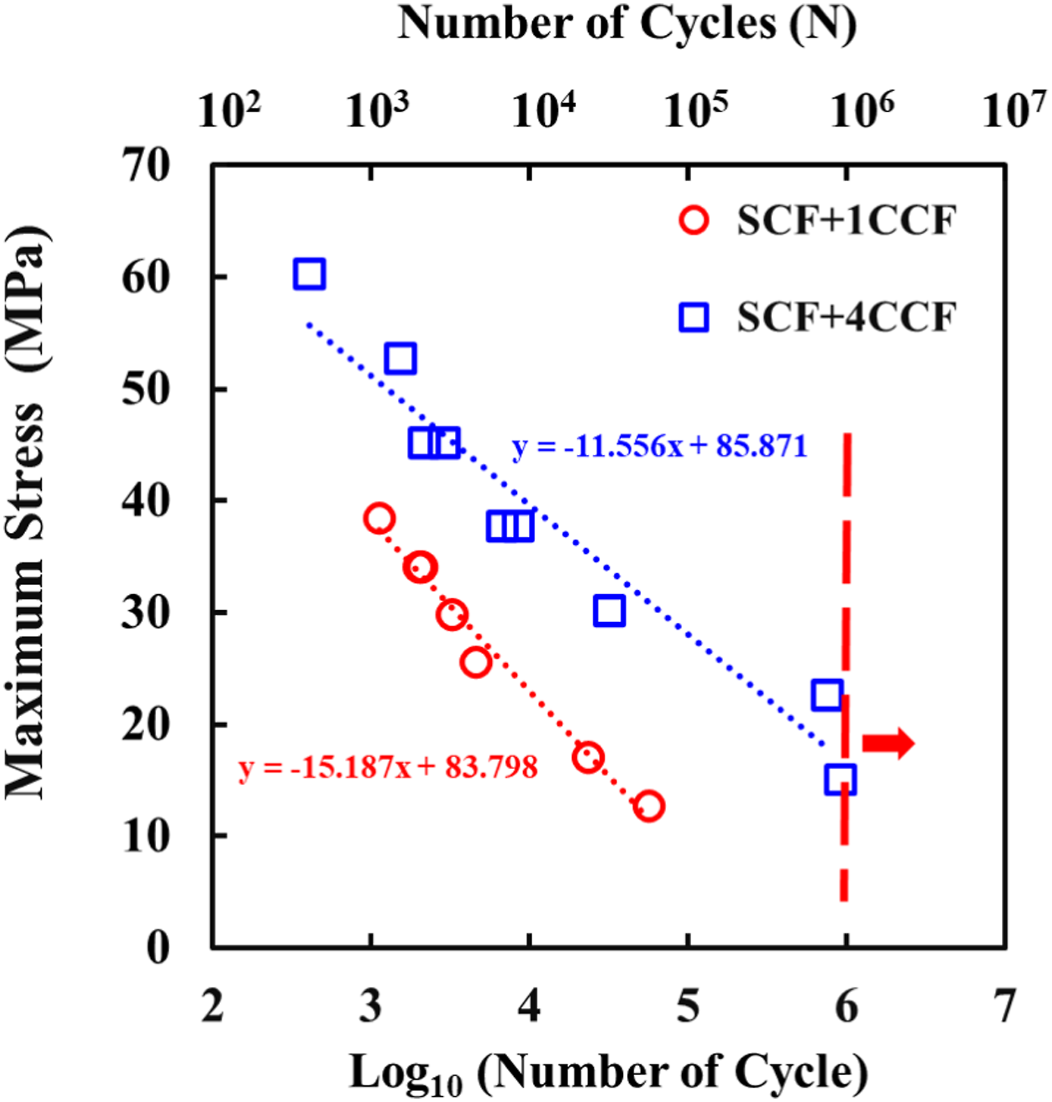
Since the ultimate tensile strength of SCF+1CCF and SCF+4CCF composites are different, the maximum stress versus the number of cycles plot is insufficient to fully compare the fatigue life of these two different composites. Thus, the stress in the S-N curves is normalized by the quasi-static strength of the composites in Figure 8. Normalization of the fatigue stress reduces the effect of fiber volume fraction. Similar to the non-normalized S-N curve, the normalized S-N curve formed by the SCF+1CCF composite is also significantly steeper than the SCF+4CCF composite. The regression line of the SCF+1CCF composite has a slope of −35.53 which is almost 132% steeper than the slope of the SCF+4CCF composite. The normalized S-N curves of the SCF+1CCF and SCF+4CCF composites intersect each other at log10 N = 4.1 or approximately N = 12,590 cycles, indicating that the normalized fatigue strength of the SCF+4CCF composite exceeds that of the SCF+1CCF composite for N >12,590. Therefore, it can be concluded that the SCF+1CCF composite has higher fatigue life than the SCF+4CCF composite at high normalized fatigue stress. On the other hand, the SCF+4CCF composite exhibits a superior fatigue life under the condition of low normalized fatigue stress. Normalized S-N curves for SCF+1CCF and SCF+4CCF composites.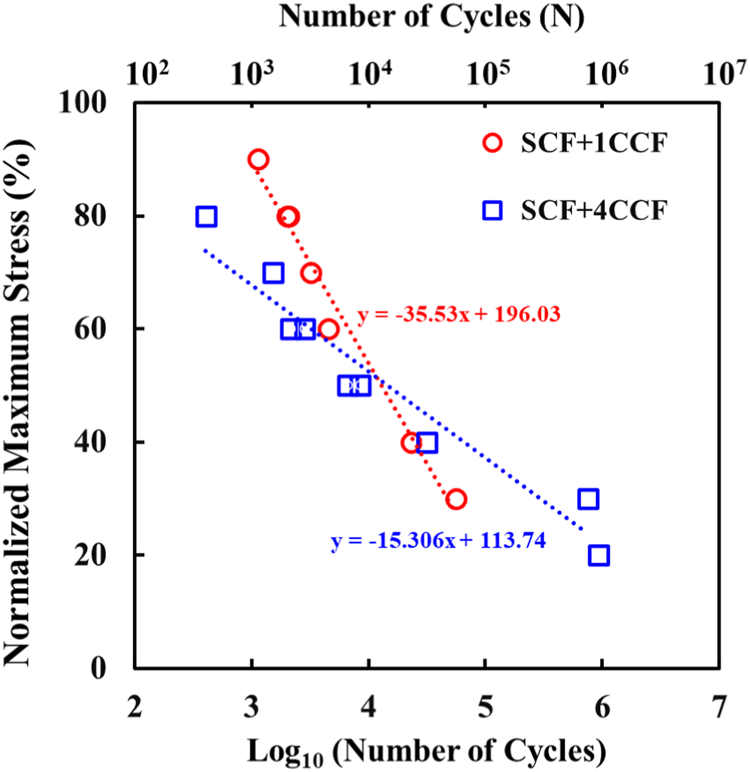
Figure 9 presents the strain-life plot for one-layer and four-layers continuous woven carbon fiber reinforced multiscale composites. The initial strain values were calculated by dividing the maximum stress displayed in Figure 7 by the quasi-static Young’s modulus and then multiplying by 100 to convert it to a percentage of strain. The modulus values used for this calculation are the pre-fatigue values as depicted in Figure 6(c). It is observed from Figure 9 that the SCF+4CCF specimens were tested at initial stains of 0.31%–1.25% whereas SCF+1CCF specimens were tested at initial strains of 0.36% to 1.09%. It has been observed that SCF+1CCF and SCF+4CCF composites when tested with an initial strain value of 0.94% or higher, exhibit nearly identical fatigue life. However, at lower initial strain values, the SCF+4CCF composite demonstrates a longer fatigue life compared to the SCF+1CCF composite. Initial strain versus cycle life curve for SCF+1CCF and SCF+4CCF composites.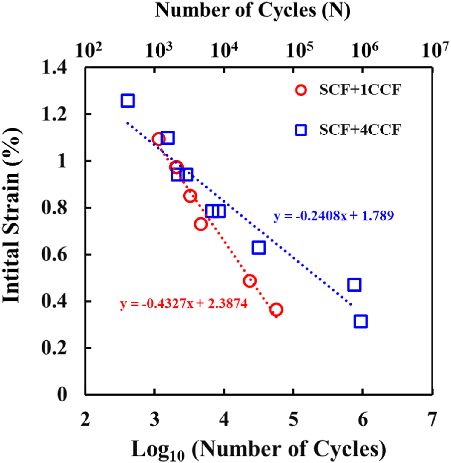
Young’s modulus degradation during fatigue
By periodically monitoring changes in Young’s modulus during fatigue testing, it is possible to gain an understanding of the progression of damage.
4
A reduction in the modulus at a macroscopic level reflects damage at the microscope level, such as matrix cracks, fiber/matrix interfacial failure, and so on.
26
The modulus values are normalized by the modulus of the specimen in an undamaged state. Similarly, cycles are normalized by the total number of cycles to failure and are therefore referred to as normalized cycles. The reduction of the normalized modulus for SCF+1CCF and SCF+4CCF composites at different normalized fatigue strengths is depicted in Figures 10(a) and (b). It is observed that higher normalized fatigue stress leads to a reduction in the modulus of the composites following a nearly linear trend. Conversely, under lower fatigue stress, the multiscale composites exhibit a rapid decrease in tensile modulus during the early stages of fatigue and then a relatively slow rate of modulus degradation until the last measured modulus prior to fatigue failure. The multiscale composites have a large number of interfaces due to the presence of short carbon fiber in the ABS matrix and continuous carbon fibers and at selected layer locations. At the early stage, micro-damages can be expected to initiate at weak spots along fiber matrix interfaces, voids around the short carbon fibers, and the pores in the ABS matrix.3,27 It is anticipated that the rapid reduction of the modulus at the early stage is caused by the initiation of widely dispersed microscopic damage where defects increase local strain energies.
3
The gradual reduction of the modulus at the next stage indicates a slow progression of the previously formed cracks in the ABS as well as at the fiber-matrix interfaces.28,29 Figure 10(c) shows a comparison of the normalized modulus changes between of the SCF+1CCF and SCF+4CCF composites when tested at 40% of their ultimate tensile strength. The results reveal that the SCF+4CCF composite experiences a significantly greater reduction in modulus throughout its fatigue life compared to the SCF+1CCF composite. Specifically, the modulus of the SCF+4CCF composite decreases by approximately 40% before failure, whereas the SCF+1CCF composite decreases by only about 20% prior to failure. As mentioned above, damage initiates from the weak spots along fiber matrix interfaces, pores, and voids. Subsequently, this damage propagates between the fiber matrix interfaces. Since the SCF+4CCF composite has more fiber matrix interfaces as well as higher void content than the SCF+1CCF composite, more damage accumulates in the SCF+4CCF composite which causes higher degradation in normalized modulus during fatigue. Normalized Young’s modulus versus normalized cycles of (a) SCF+1CCF composite (b) SCF+4CCF composite (c) SCF+1CCF and SCF+4CCF composites cyclically loaded at 40% of their ultimate tensile strength.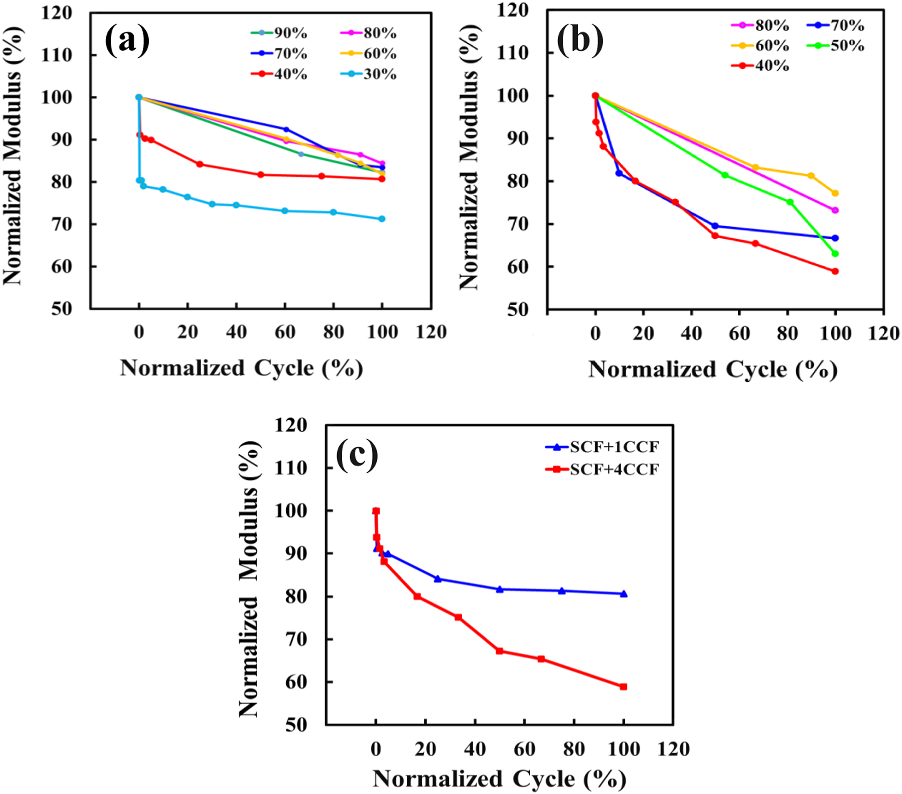
The difference in modulus degradation of SCF+1CCF and SCF+4CCF composites gives an insight to damage progression under fatigue loading. These observations offer valuable insights into optimizing multiscale composites for enhanced fatigue performance. The varying modulus reduction between these composites might indicate differing stress distribution and damage mechanisms during fatigue. Analyzing these differences can help understand how stress propagates through the material and how various scales of reinforcement affect stress concentration and dissipation. The higher rate of modulus reduction in SCF+4CCF versus SCF+1CCF indicates more damage accumulation due to the higher amount of fiber-matrix interfaces in the former. It also indicates that optimizing the interface between fibers and matrix is crucial for improving fatigue resistance.
Failure analysis
Macroscopic failure analysis under fatigue
Figure 11 shows photographs of the fracture surfaces of SCF+1CCF and SCF+ 4CCF composites that failed under fatigue loading. Initially, a visual inspection was conducted to analyze macroscopic failures resulting from fatigue loading. It is observed that the multiscale composites experienced complete separation into two pieces in the gauge section, with the failure occurring perpendicular to the loading direction due to matrix and fiber failure. Fiber pull-out and matrix cracking are identified as the major failure modes under cyclic loading. In the fused filament fabrication process, the heated nozzle extruded the molten polymer along the predetermined raster lines side-by-side to create each laminate. Each of these lines is known as a bead. Due to the temperature and pressure conditions during printing, there are always micro voids at the interface between adjacent beads.
30
Additionally, the short carbon fibers into the ABS filament and weak fiber/matrix bond within the woven fabric layers generate micro voids.24,31 It is anticipated that micro-cracks first arise from voids in the material and gradually develop into macroscopically visible cracks as the number of loading cycles increases. However, during this phase of the fatigue process, the load is increasingly carried by the continuous woven carbon fibers. As the number of loading cycles continues to increase, the cracks eventually propagate and reach the interface between the continuous fibers and the matrix. Once the cracks reach this interface, they merge with the interfacial voids around the continuous fiber, which then initiate interfacial debonding.
32
As the composite approaches fatigue failure, the continuous carbon fibers inside the matrix begin to rupture and break away from the surrounding SCF-reinforced ABS matrix. Ultimately, the SCF-reinforced ABS matrix fractures, and the continuous fibers are pulled out from the matrix. Failure patterns in SCF+ 1CCF composite primarily exhibit single fractures, as depicted in Figure 11(a). The damage is confined to a localized region of the specimen and occurs suddenly. Moreover, there is minimal evidence of matrix cracking, suggesting that the fatigue process in the SCF+1CCF composite is predominantly governed by fiber behavior. Fatigue fracture surfaces of (a) SCF+ 1CCF composite (b) SCF+ 4CCF composite.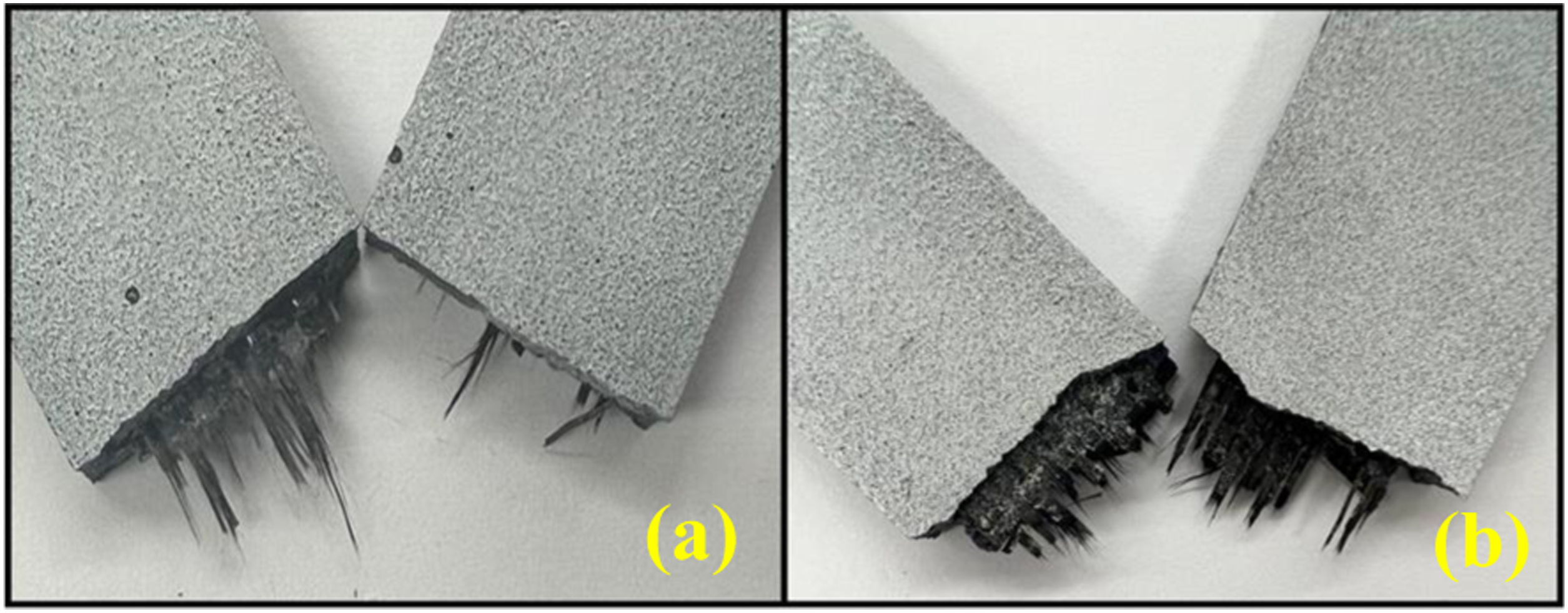
Typical fracture surfaces of SCF+ 4CCF composite specimens subjected to different stress levels are shown in Figure 12. Although the composite failure is attributed to fiber pullout, it is noticed that the extent of fiber pullout heightened as the stress levels decreased. Notably, the composite loaded with 40% normalized strength exhibits a greater degree of fiber pullout compared to those loaded at 80% of their ultimate tensile strength. At high normalized stress levels, the cyclic stress is close to the ultimate strength of the composite. As a result, failure takes place due to progressive fiber breaking with minimal fiber-matrix debonding where fibers are broken within the first few cycles.
28
On the other hand, at lower stress levels, the composite endured a greater number of loading cycles before failure which allows matrix cracks to propagate transversely along the fiber and fiber-matrix interface which led to progressive interface debonding. The strength of the fibers is weakened by wear-induced breakage, which initiates damage growth and ultimately leads to complete fracture under fatigue loading.
33
The existence of the transverse cracks as shown in Figure 13 at low cyclic stress levels also indicates progressive matrix cracking. Fatigue fracture surfaces of SCF+ 4CCF composite specimens subjected to different normalized stress levels. Presence of transverse cracks of a fatigue failed SCF+4CCF composite loaded with 40% normalized strength.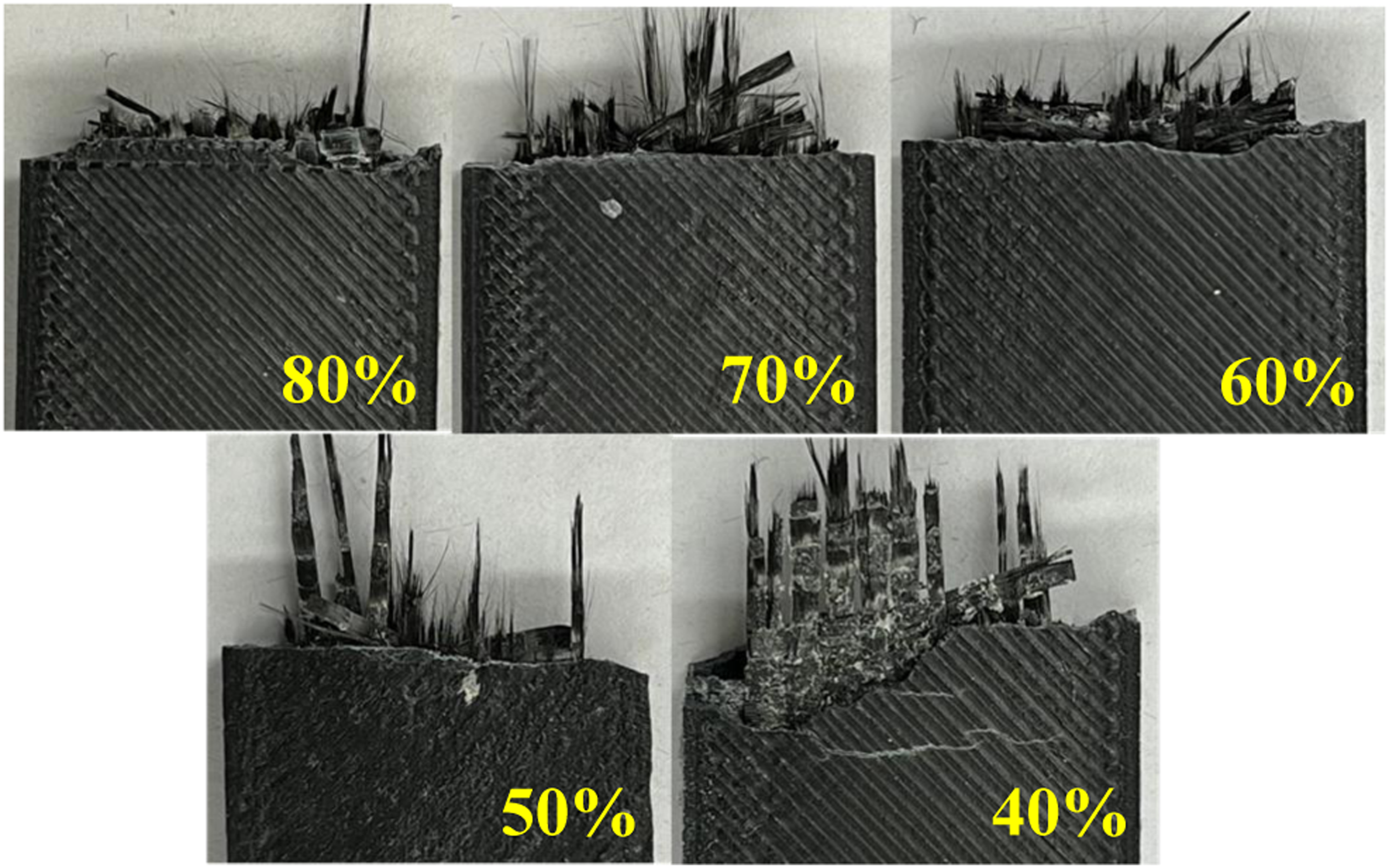
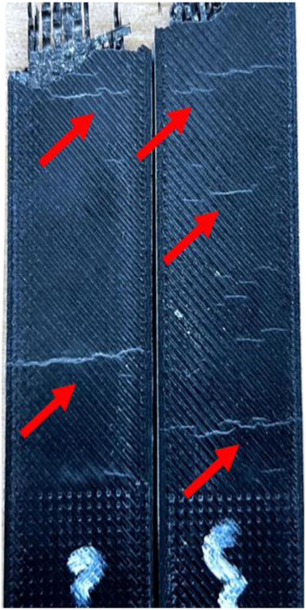
SCF+ 4CCF composites subjected to 30% and 20% of their maximum stress failed due to transverse cracking and delamination. The failure of SCF+ 4CCF composites subjected to 30% and 20% of their maximum stress was preceded by matrix cracking and delamination. These damage modes occurred throughout the entire gage section between the grips. Visual inspection during testing revealed the presence of matrix cracks and delamination at the specimen’s edge as shown in Figure 14(a). The delaminations were observed to open and close slightly with cyclic loading, indicating the progressive nature of the delamination process. Under cyclic loading, the repeated application of stresses led to the initiation and propagation of internal cracks, which eventually resulted in delamination between layers in the composite, as shown in Figure 14(b). Additionally, transverse cracks also exist in the SCF-reinforced ABS matrix on the surfaces as shown in Figure 14(c). Delamination and cohesive failure within the matrix near the interfaces suggested areas vulnerable to fatigue-induced damage. Delamination of SCF+4CCF composite (a) during testing (b) after failure, (c) transverse cracks in the SCF-reinforced ABS matrix.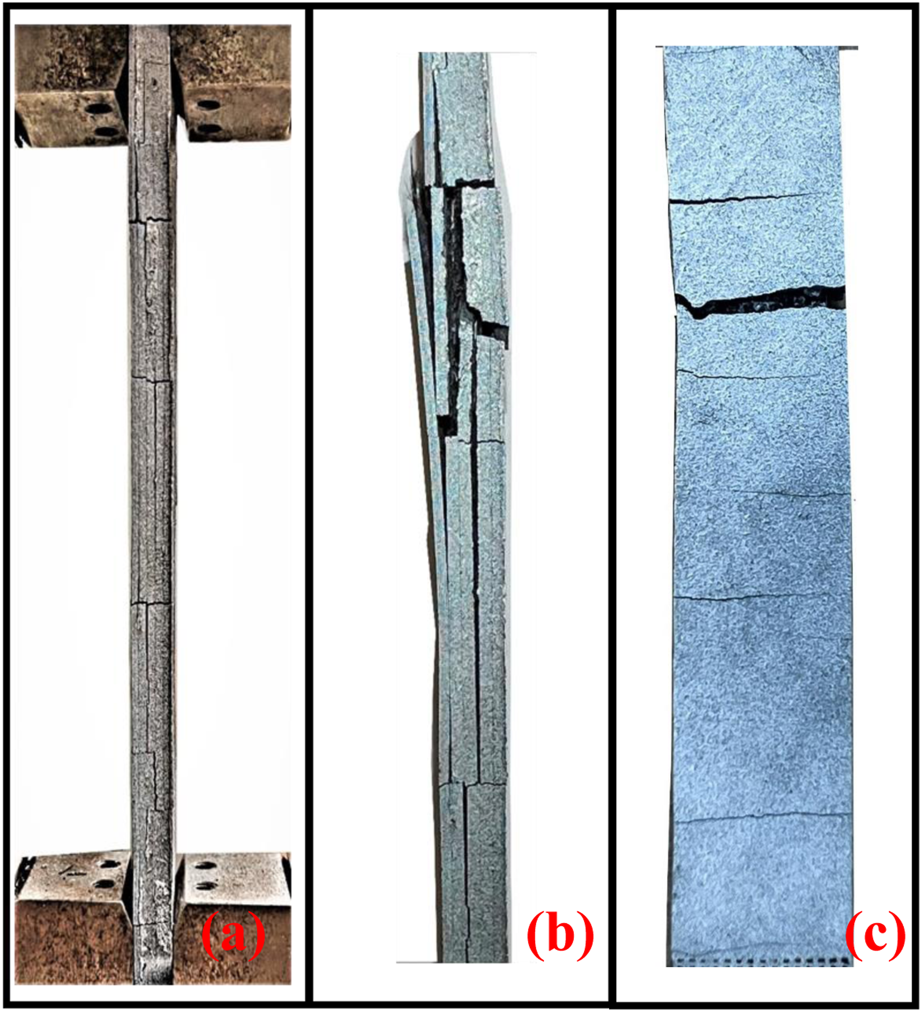
Microscopic failure analysis under fatigue
The failure process near the short carbon fibers was investigated by analyzing the fracture surface of the broken specimens under a scanning electron microscope. The micrograph as shown in Figure 15 shows fractured and pulled out short carbon fibers on the fracture surface. A closer look at a single carbon fiber in a higher-magnification micrograph, as shown in Figure 15(b), reveals an inclined broken surface. Such an inclined failure surface indicates a shear failure, which occurred because of the off-axis orientation of the short carbon fiber. The side view of the single fiber as shown in Figure 15(d) shows a smooth fiber surface with a small presence of ABS residue and void around the carbon fiber. The smooth fiber surface and matrix surface where fibers have pulled out (Figure 15(a)–(d)) are evidence of a poor fiber-matrix bond strength. The reduced stress transfer mechanism at the fiber/matrix interface can lead to the weakly bonded fiber acting as a cylindrical void, which can lead to larger-scale matrix cracking with continued cyclic loading.
34
(a) SEM micrographs of fracture surface of hybrid composite. (b) SEM micrograph of the short carbon fiber highlighted by the right solid box in (a). (c) SEM micrograph of the fracture surface highlighted by the left solid box in (a). (d) SEM micrograph of side view of short carbon fibers shown in (b).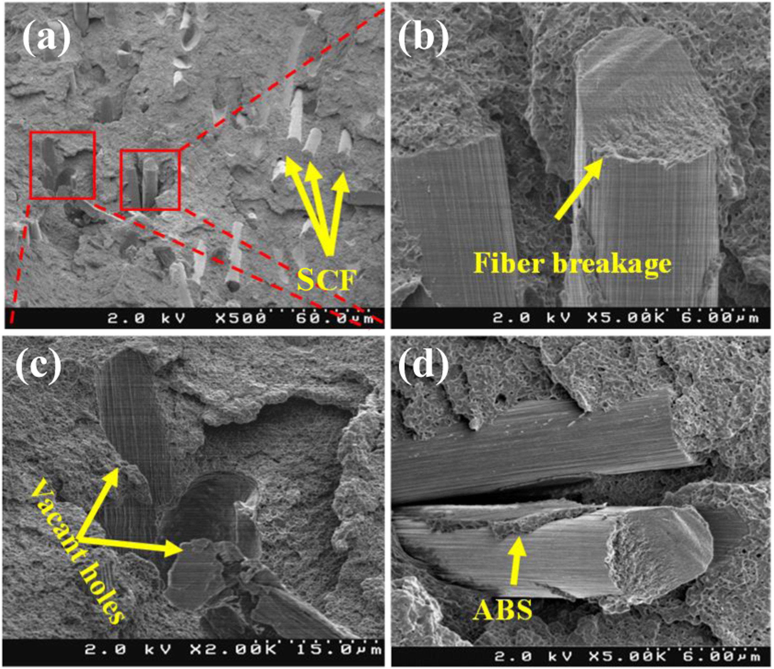
Full-field fatigue damage analysis by using DIC
In this study, a two-dimensional DIC analysis was performed to get the full-field strain distribution. A full-field strain distribution provides insights into the macroscopic crack initiations and propagation in the specimens. During fatigue testing, intermittent pauses were taken to capture images for the DIC analysis. The images were correlated with the undeformed state of the specimens to get full-field strain in the loading direction ( Full-field strain in a SCF+ 1CCF composite at different loading cycles at 40% of the ultimate tensile strength.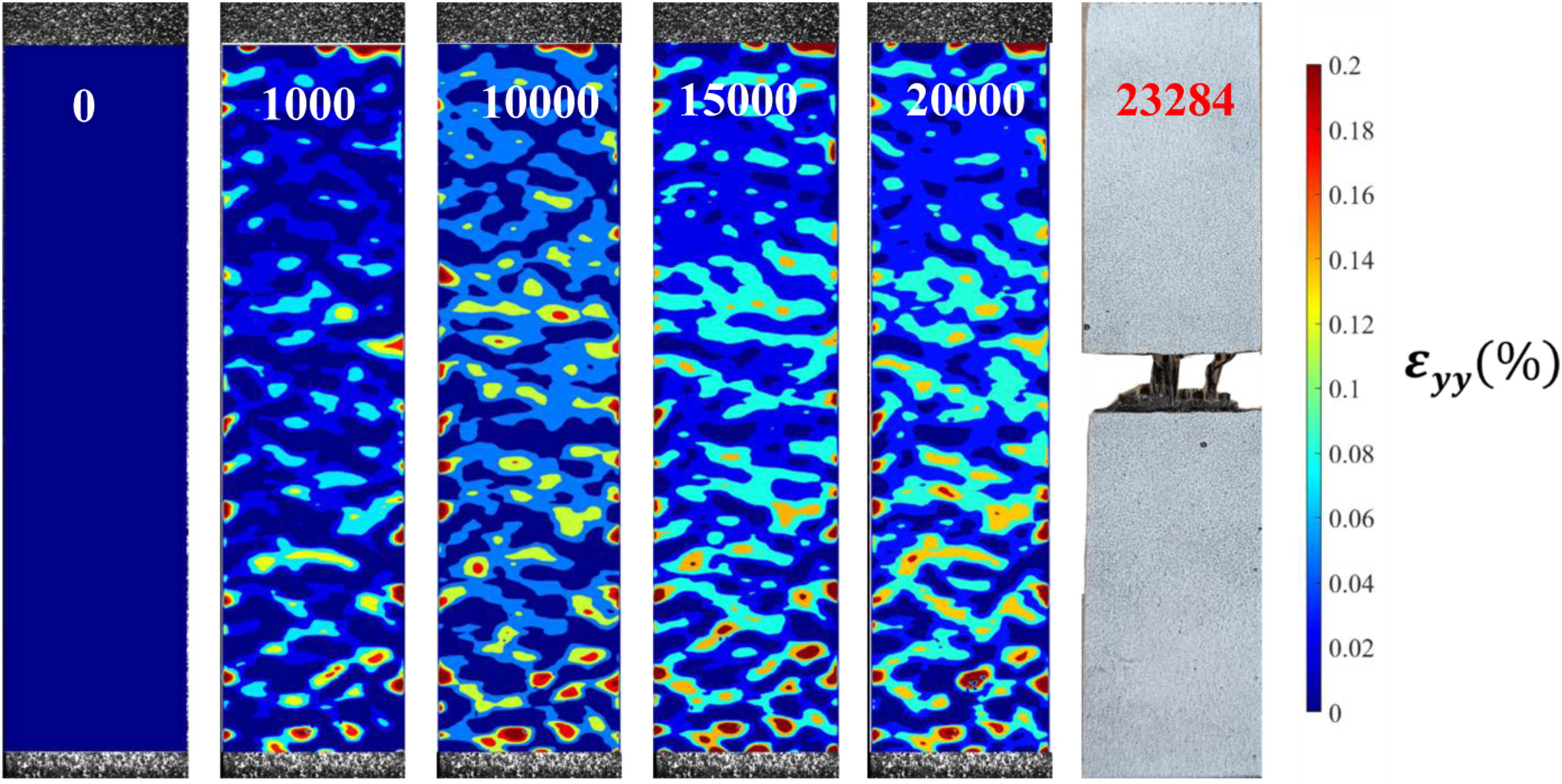
Figure 17 shows the evolution of damage in a SCF+ 4CCF composite subjected to a normalized cyclic load level of 40%. The initial modulus of this composite was 5.66 GPa. The presence of macroscopic damage was not observed before 104 cycles. At 104 cycles, some randomly located concentrated strain regions appeared at the lower middle portion of the specimen. As the cycles increased to 15,000, a localized high-strain region appeared at the right bottom corner of the specimen, as shown in Figure 17, which was visually correlated to a subsurface transverse crack. The average strain of this zone was 4200 Full-field strain in a SCF+ 4CCF composite at different loading cycles at 40% of ultimate tensile strength.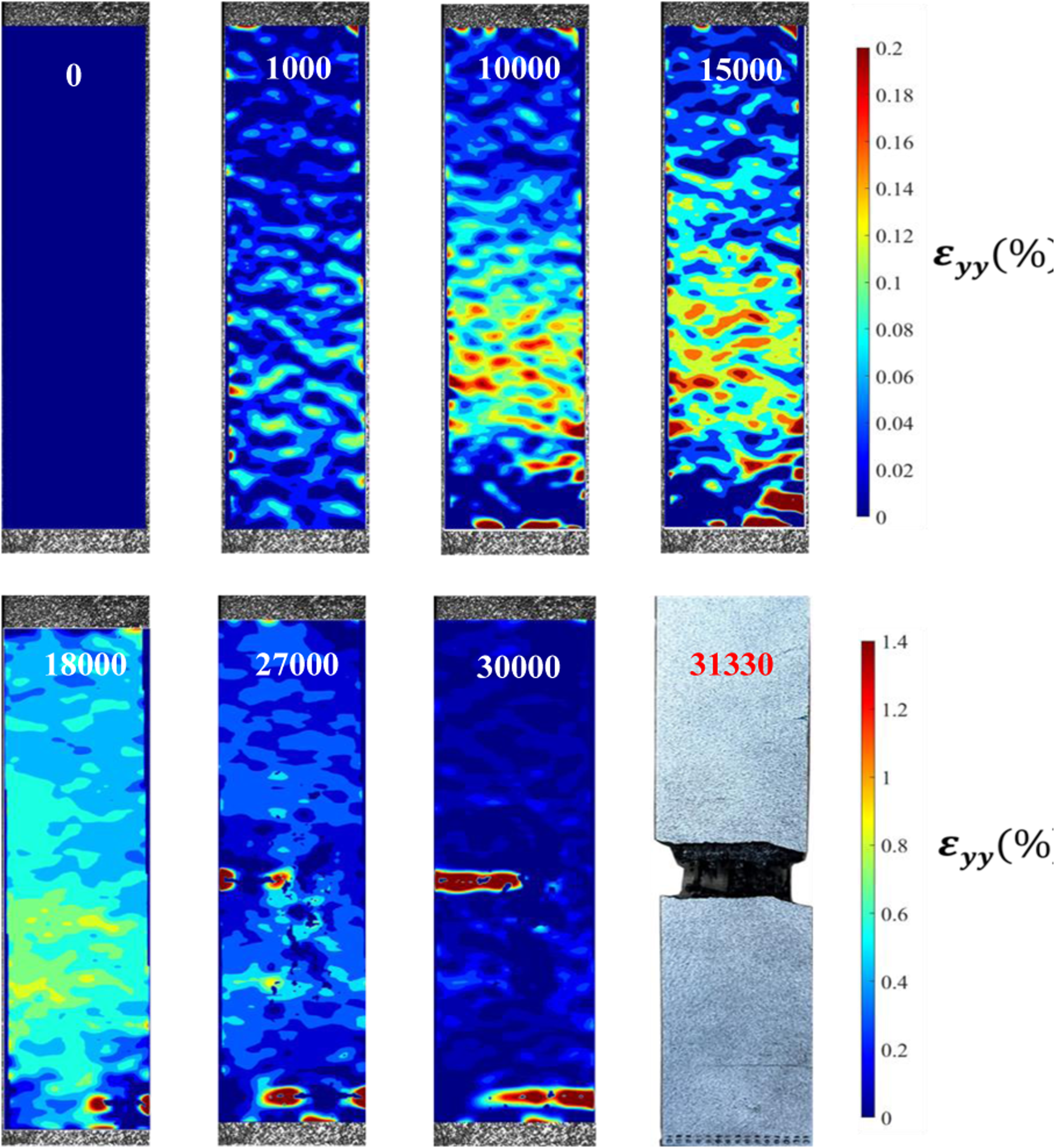
Conclusion
This study investigated the quasi-static tension and tension fatigue behavior of a novel type of additively manufactured multiscale composite containing short carbon fibers (SCF) and layers of woven continuous carbon fibers (CCF). The key conclusions drawn from this research are as follows: 1. The multiscale composites containing one woven layer (SCF+1CCF) and four woven layers (SCF+4CCF) exhibited superior quasi-static tensile strength and modulus compared to both neat ABS and SCF-reinforced ABS composites. 2. The SCF+4CCF composite demonstrated enhanced strength during high cycle fatigue, particularly for lifetimes exceeding 104 cycles. 3. The S-N data with stress level normalized by the quasi-static strength revealed that the SCF+1CCF composite degraded 133% faster than the SCF+4CCF composite. 4. During fatigue testing, the SCF+4CCF composite showed evidence of fiber pull-out, widespread matrix cracking, and delamination, whereas the SCF+1CCF composite experienced minimal damage until sudden, fiber-dominated failure. 5. The principal failure modes at the microscopic level included fiber pull-out and fiber breakage.
Recommendations for future work
While our study specifically focused on multiscale composites comprising specific combinations of SCF and CCF within an ABS matrix, the fundamental principles observed in this research may have applicability to other composite systems with similar reinforcing fibers. However, it is crucial to note that different materials possess unique mechanical properties and interfacial behaviors, potentially affecting the transferability of our findings. The observed improvements in mechanical properties and fatigue resistance are contingent upon the specific fabrication methods utilized in our study. Variations in fabrication techniques, such as different layering sequences, processing parameters, or methods of incorporating the fibers, may result in distinct mechanical behavior. Moreover, the compatibility between the reinforcing fibers and the matrix material, as well as the strength of the interfacial bonding also affect the mechanical behavior. Future investigations involving different fiber types, matrix materials, or reinforcement architectures would provide a clearer understanding of the fatigue behavior of additively manufactured material with short and continuous carbon fiber.
Supplemental Material
Supplemental Material - Tensile fatigue behavior of short and continuous carbon fiber reinforced additively manufactured thermoplastic multiscale composite
Supplemental Material for Tensile fatigue behavior of short and continuous carbon fiber reinforced additively manufactured thermoplastic multiscale composite by Md. Fazlay Rabbi, James Ertter, III and Charles E Bakis in Journal of Reinforced Plastics and Composites
Footnotes
Acknowledgements
The authors express their gratitude for the assistance provided by Dr Henrietta Tsosie and Mr Henry Dyer during fatigue testing. Additionally, they acknowledge Dr Richard C. Bell for his contribution to the SEM analysis. Special appreciation goes to Dr Todd D. Batzel for facilitating access to the DIC facility and to the Penn State Multi Campus Research Experience for Undergraduate (MC REU) program for providing financial support.
Declaration of conflicting interests
The author(s) declared no potential conflicts of interest with respect to the research, authorship, and/or publication of this article.
Funding
The author(s) received no financial support for the research, authorship, and/or publication of this article.
Data availability statement
Data will be available upon request.
Supplemental Material
Supplemental material for this article is available online.
References
Supplementary Material
Please find the following supplemental material available below.
For Open Access articles published under a Creative Commons License, all supplemental material carries the same license as the article it is associated with.
For non-Open Access articles published, all supplemental material carries a non-exclusive license, and permission requests for re-use of supplemental material or any part of supplemental material shall be sent directly to the copyright owner as specified in the copyright notice associated with the article.