
Abstract
A novel approach for generating internal pressure in filament-wound cylinders using the compressed elastomer method is investigated. Pressure is exerted on the inner surface of the cylinder by radially expanding elastomeric discs inside the composite cylindrical shell. This is accomplished by applying a uniaxial compressive load to the discs with the aid of rigs placed between compression platens in an ordinary universal testing machine. The digital image correlation (DIC) technique is employed to assist the tests in mapping both strain and displacement fields during the entire testing process. Cylinders with six different winding angles (±35°, ±45°, ±55°, ±65°, ±75°, and ±90°) are prepared and analysed. Their load-carrying capacity increases up to an angle of ±75°, accompanied by systematic changes in deformation and failure mechanisms. The suggested testing setup offers benefits in evaluating the impact of processing parameters on the internal pressure strength of filament-wound cylinders. It serves as a secure and cost-efficient laboratory-scale alternative to conventional hydrostatic pressure testing.
Keywords
Introduction
Fibre-reinforced cylindrical shells have proven to be effective as load-bearing elements in pipes1–4 and pressure vessels5–8 for transmitting and storing pressurised fluids. They are especially advantageous for operations in harsh environmental conditions9,10 and in applications where weight is critical,11,12 as in hydrogen storage.13–15 The safe operation of these structures under internal pressure is closely related to their radial deformation, which is controlled by hoop tensile properties, including tensile stiffness, ultimate strain, and strength. 16
Filament winding (FW) is among the most important composite manufacturing techniques,
17
being particularly well-suited for producing hollow solids of revolution, where reinforcing fibres are positioned in an oriented pattern for enhanced structural efficiency.
18
The process is not only cost-effective, with minimal material waste,
19
but also meets the high fibre volume requirements of high-performance structures.
20
Nevertheless, the filament-wound layer is inherently intricate, exhibiting a distinctive regular mosaic pattern, consisting of triangular-shaped two-ply units with alternating
As usual for laminates with continuous fibres, the mechanical behaviour of filament-wound parts is strongly dependent on the fibre direction. 22 Moreover, FW manufacturing parameters, such as fibre tension, 23 and possible deviations from design specifications (e.g., layer thickness and winding angles) 24 exert significant influence on the mechanical response of these structures. 25 These uncertainties and variability may affect the range of operating pressure, possibly compromising the strength of the composite. 23 Therefore, pressure vessels for critical applications demand at least one valid burst test for each batch of cylinders, and the difference between burst pressure and maximum service pressure determines the true margin of safety. 26
There are some experimental methods available for determining burst pressure and hoop tensile properties of composite vessels, including hydrostatic pressure and ring specimen tests. In the former, the structure is filled in with a liquid, usually water or oil, and the pressure increases up to failure. While this method yields reliable data, it carries notable risks when a violent burst occurs. In addition, it is costly due to the need for specialised equipment, including a pump, thick flanges with O-rings for sealing, and axial beams to prevent the axial displacement of the cylinder and the flanges from being pushed off the sample.27–29 In ring tests, a tensile load is applied on a ring specimen extracted from cylinders,30–33 being much simpler and less expensive than hydrostatic pressure tests. However, they present an important limitation related to the difficulty in assessing the behaviour of helical layers of filament-wound cylindrical shells. 34
An alternative approach was proposed by Mosley, 35 a burst pressure test in which the cylinder is partially pressurised by an elastomeric insert inside it. The insert is axially loaded by two pistons, causing its radial expansion and contact with the cylinder under testing. This was the basis for establishing the standard test method ASTM C1819. 36 The accuracy of this method was investigated by Carter 37 using a steel control sample, and the internal pressure was calculated from linear elastic and hyper-elastic equations. The values were checked with a pressure value found via a Lamé cylinder analysis of the experimental hoop strain. The values from linear elastic, hyper-elastic, and Lamé solutions showed sharp agreement, and notably high pressures, exceeding 340 MPa.
Some works in the literature have exploited this experimental approach. Vandeput 38 used a polyurethane (PU) insert to assess the hoop tensile strength distribution of cemented tungsten carbide tubes. The results were correlated with the transverse strength distribution from three-point bending tests using statistical fracture theories. Hong et al. 39 reported a miniaturised version of the method for tubular ceramic specimens of commercial alumina and silicon carbide. A PU cylindrical rod was utilised, and statistically consistent strength data compared to diametrical loading was obtained. Jacobsen et al. 40 measured the hoop strength of tubular silicon carbide fibre-reinforced composite specimens using C-ring and compressed elastomer tests, and the results showed agreement within a 6% margin. Shapovalov et al. 41 assessed different test methods for open and closed ends tubes of reinforced silicon carbide matrix composite. They measured pressure at the proportional limit and at ultimate failure and analysed the strain fields using DIC. While the closed-end hydraulic burst test reached the proportional limit at higher pressure, the compressed elastomer method yielded higher elastic modulus, hoop strain, and ultimate failure pressure. Nevertheless, the results were considered consistent given the typical scatter in properties for ceramic composites.
Optical methods using DIC are an excellent tool to study the behaviour of composites under mechanical loading. The DIC technique is most used to measure deformation and displacement fields of parts by tracking the grey value pattern in small neighbourhoods, referred to as subsets, during straining. Castro et al. 42 introduced a methodology for measuring geometric imperfections of 3D filament-wound cylinders with DIC and only one pair of cameras. The developed procedure is depicted in detail allowing straightforward implementation to other structures and includes proper lighting, focus adjustment, calibration, environment, stitching process, and surface reconstruction. Later, the authors exported the geometric imperfections to finite element (FE) software to generate FE meshes using experimentally measured imperfections. 43
Given the safety concerns associated with hydrostatic pressure testing and the inherent restrictions of ring specimen tests, it is worth exploring alternative testing methods. The compressed elastomer technique shows desirable features, although it has not yet been properly employed for filament-wound cylinders. Therefore, this work proposes and evaluates a laboratory-scale testing setup for pressurising such cylindrical shells by the radial expansion of elastomeric discs that undergo compression loading through rigs in an ordinary universal testing machine. The deformation response is monitored by DIC, and several winding angles are examined and discussed.
Experimental details
The design of composite cylindrical shells is developed in CADWIND® software,
43
with two antisymmetric angle-ply
The cylinders are manufactured by winding carbon fibre tows pre-impregnated with epoxy resin (SIGRAFIL® C T24-5.0/270-E100, from SGL Carbon) around a cylindrical stainless-steel mandrel with a 50 mm diameter, using the desktop filament winder machine X-Winder, model 4X-23 (Figure 1). Before each winding, a release agent (S-31, from Jost Chemicals) is applied to the surface of the mandrel. Shrink tape is wrapped after the end of the winding to aid consolidation of the wound layers. The system is cured in a horizontal oven with air circulation at a heating rate of 3°C/min up to 140°C and held at that temperature for 45 min. After being cured, the composite is cooled down to room temperature and extracted from the mandrel. Cylindrical specimens are cut using a diamond saw with water jet cooling to prevent microcracks and higher temperatures. The samples are then painted to produce a speckled pattern to allow surface deformation tracking and correlation matching to make them well-suited for DICtracking analysis. Filament winding manufacturing process.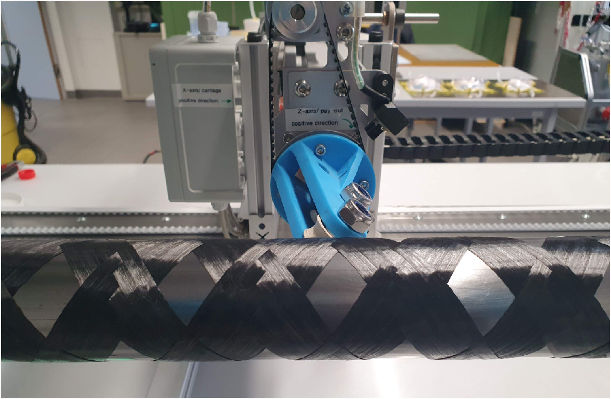
The proposed pressure test procedure is an adaptation of the ASTM C1819 standard. The test consists of applying a uniaxial compressive load only on elastomeric discs concentrically inserted inside the cylinder, without any direct compressive force on the composite specimen. Radial expansion of the elastomeric inserts is achieved through the compressibility effect, transmitting the applied load to the cylinder wall. In the analysis of the partially pressurised cylinder, the unpressurised ends are assumed infinitely long. When the cylinder is pressurised in the central part of its length, the hoop stress varies along the length and bending stresses occur in the axial direction. Moreover, shear stresses act at right angles to the cylinder axis and compressive stresses due to the pressure may be present solely in the pressurised length. Despite this complex stress state, it is noteworthy that the hoop stress remains the largest among the three stress systems (see Figure 5 in Reference 35).
The elastomeric inserts must have their quasi-incompressibility checked to reach Poisson’s ratio of 0.5 or as close to it as possible. The discs are produced by casting a two-component ADDV-42 silicone rubber (40 Shore A hardness) into 3D-printed open-top moulds, being 10 mm in height and 49.8 mm in diameter. To obtain discs with a smooth and uniform surface finish, a glass plate is carefully positioned on the top of the moulds during the solidification process. Before being inserted into the cylinder, the discs are covered with talcum powder to minimise friction effects. Two pushrods are then fitted to the ends of the cylinder, with a clearance of 0.05 mm. The pushrods are machined from SAE 1040 steel, with a black oxidation surface treatment.
The test rig assembly is schematically illustrated in Figure 2, in which the pressure testing rig is positioned between two compression platens on a Zwick Roel universal testing machine equipped with a 100 kN load cell. Tests are conducted at a displacement rate of 10 mm/min, selected to minimise the potential effects of slow crack growth. Proposed internal pressure test rig.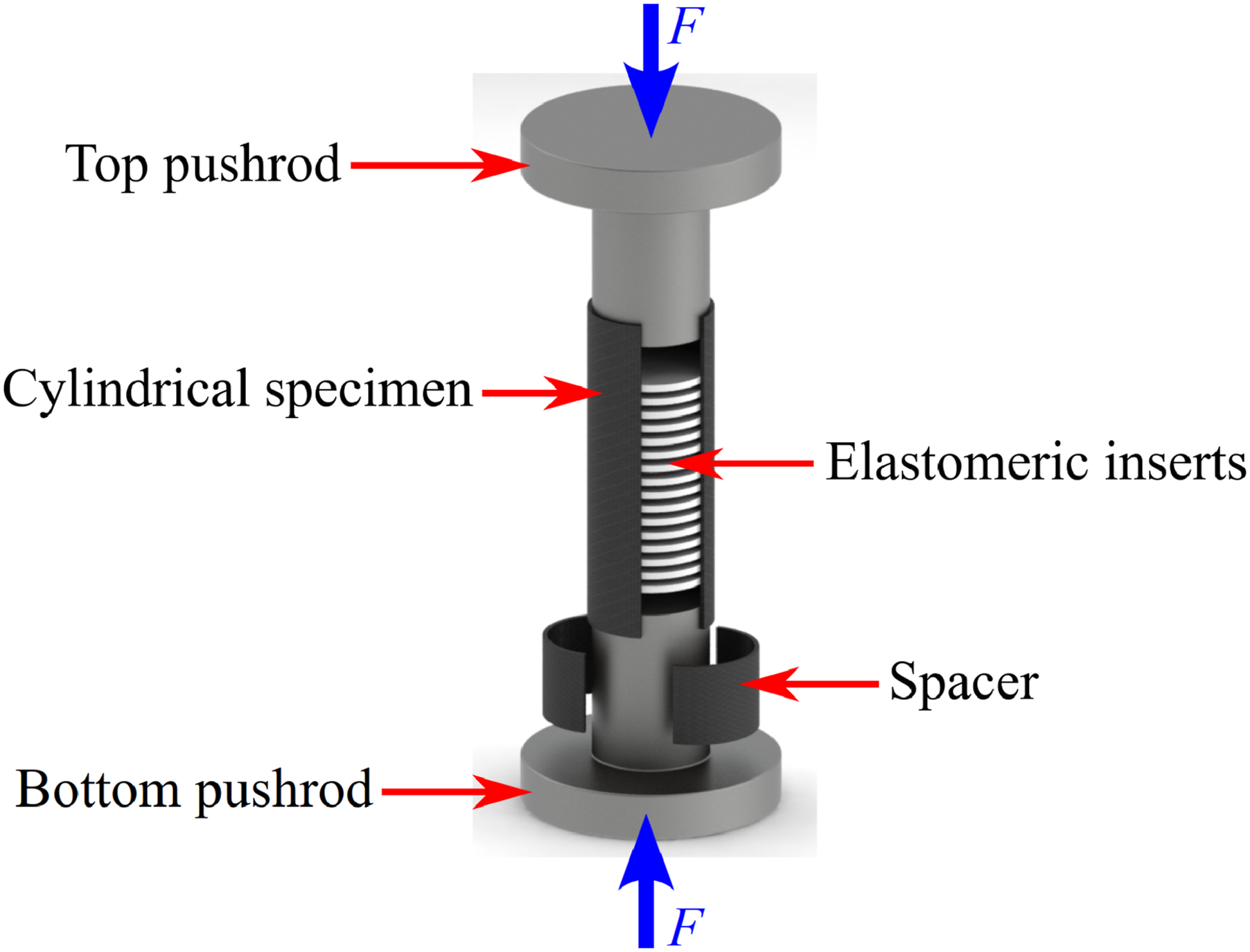
During the tests, a high-resolution ARAMIS 3D camera system, consisting of two 12-megapixel cameras and a blue light projector, is utilised to acquire images on about 60° of the cylinder’s surface. The sampling frequency is set to 5 Hz. These images are then post-processed using GOM Correlate Pro software (ZEISS Quality Suite) to measure global displacements and strain fields through the DIC method. Figure 3 shows the full experimental setup used. (a) Test rig coupled to the testing machine with the DIC system. (b) Zoom-in highlighting the speckle pattern, and (c)discretisation of the speckled image onto a surface mesh.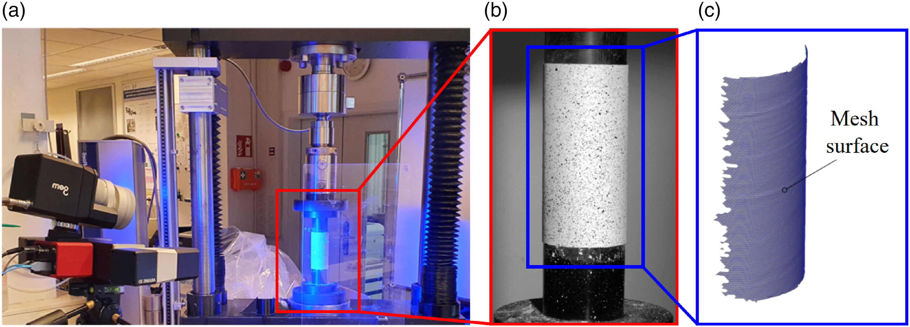
Dimensional requirements of test
The effective length of the pressurised region, located halfway in the cylinder and filled with elastomeric inserts, as well as the unpressurised ends, where the pushrods are introduced, must be determined for the success of this test. When appropriately dimensioned, the unpressurised ends allow neglecting the stresses induced by edge effects, and the stresses over the pressurised region remain reasonably constant. Furthermore, the dimensional changes at the ends of the cylinder do not significantly affect the pressurised region, as these are limited to lengths very close to the pressure surface of the pushrods, decaying steeply when moving away from them.
45
The lengths of the pressurised and unpressurised regions are determined based on the parameter
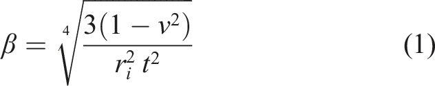
Previous studies (35,37,46) have shown that there is a stabilisation of both hoop and axial stresses when the length of the pressurised portion is greater than 9/
Given the in-plane Poisson’s ratio of the laminates as 0.3, and the inner radius and average thickness of the manufactured cylinders of 25 mm and 1 mm, respectively, the resulting parameter
Calculation of testing parameters
The following parameters are calculated in accordance with the ASTM C1819 standard guidelines: (i) Internal pressure exerted on the cylinder by an expansion of the elastomeric inserts, assuming incompressibility of the elastomeric discs: (ii) Hoop strength, that is, the maximum hoop stress that the material can sustain:
The hoop stiffness of the cylindrical shells can be determined in the linear-elastic range of the load × displacement curves using linear regression. To assess the statistical significance of the experimental data, normality and homogeneity of variances are first examined through the Shapiro–Wilk and Levene tests, respectively. In cases where these criteria are not met, outliers are identified and removed using a quantile-based approach. One-way analyses of variance (ANOVA) are then conducted, and if the null hypothesis is rejected, Tukey’s honestly significant difference (HSD) test is employed for mean comparisons. The statistical analyses are conducted with a significance level of 5%.
Results and discussion
Summary of the internal pressure test results.
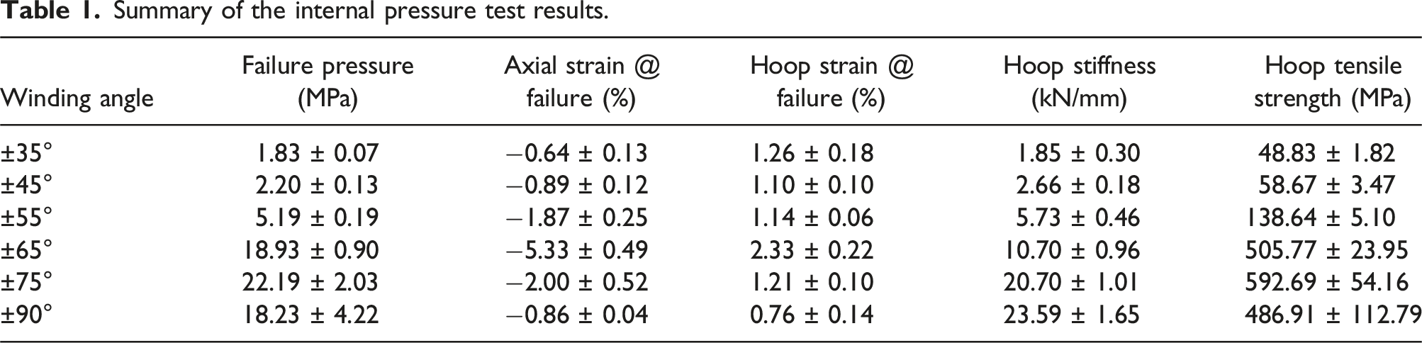
The deformation and failure processes vary according to the angle of the fibres. For cylinders wound at ±35°, the magnitude of hoop strain is higher at the failure pressure level than axial strain. The opposite is seen for cylinders with winding angles from ±55° to ±75°, where axial strain becomes predominant. Meanwhile, cylinders with fibres oriented at ±45° and ±90° display similar strains in both directions. The variation in strains is more significant in the axial direction, except for the hoop winding.
Figure 4 presents average load × displacement curves, describing simultaneously the monotonic compressive force (left axis) applied to the elastomeric discs and the corresponding internal pressure (right axis, calculated by equation (2)) resulting from their radial expansion. The sequence of events during the loading history shows an initial accommodation phase followed by a linear load increase. Within the linear regime, the stiffness of the cylinders is determined through linear regression in the 25%−50% range of ultimate load (dashed lines). The regression lines nicely fit the experimental data demonstrating a good correlation, with a coefficient of determination (R2) exceeding 0.99 for all curves. The increase in stiffness for higher winding angles is also seen in Figure 4. Applied axial compressive force and corresponding internal pressure as a function of the axial displacement for different winding angles.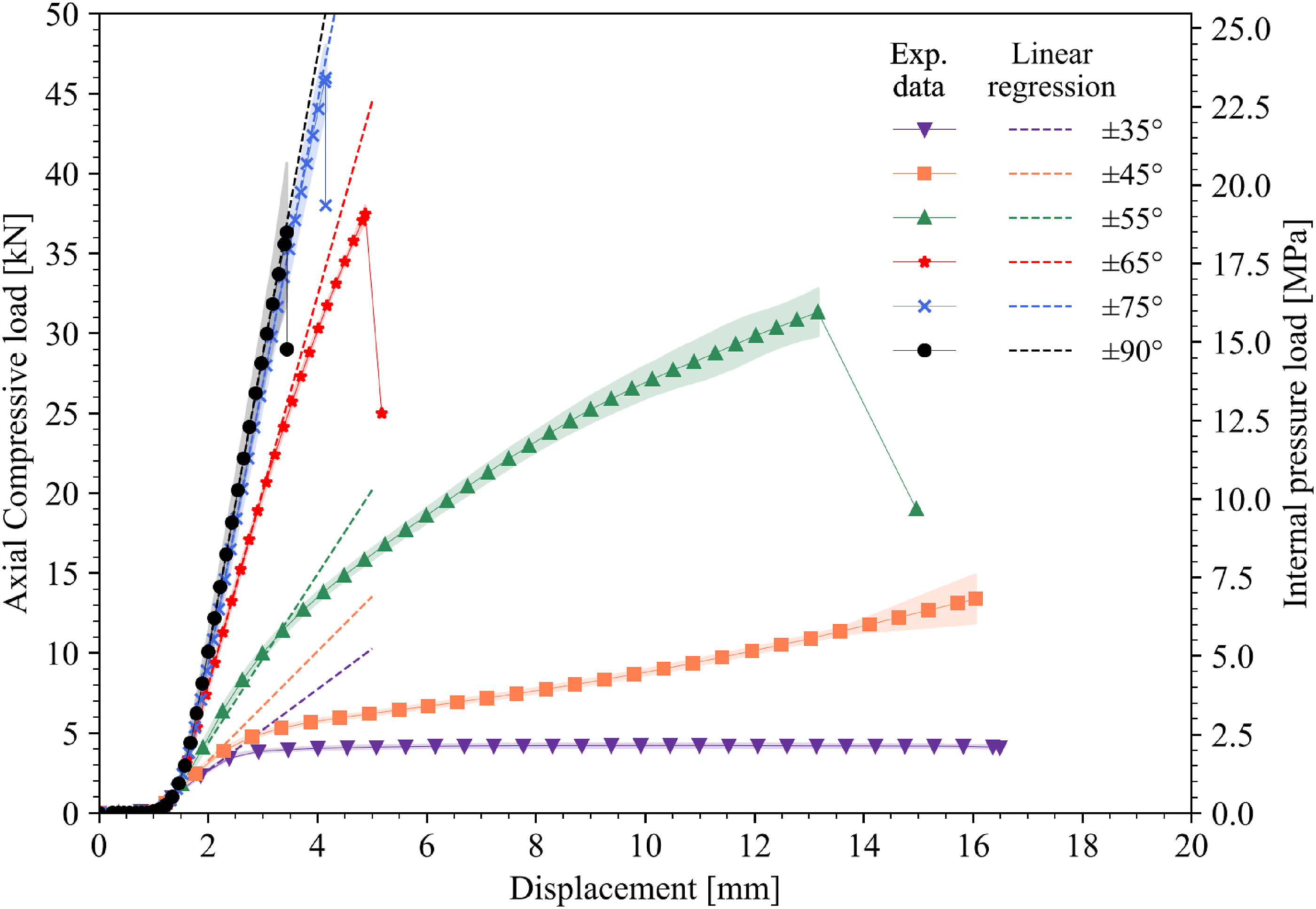
As the internal pressure increases, cylinders wound at angles of ±35°, ±45°, and ±55° exhibit a clear transition to nonlinear behaviour. Cylinders wound at ±65° show a less pronounced deviation and a lower degree of nonlinearity. In contrast, cylinders wound at ±75° and ±90° demonstrate almost linear-elastic behaviour up to failure. This behaviour can be justified by the orientation of carbon fibres closer to the hoop direction of the cylinders. The fibres play a crucial role in withstanding the generated stresses during pressurisation. Being aligned in the hoop direction, where the highest stresses occur, the fibres effectively reinforce the structure, leading to an increase in stiffness and a more linear-elastic response. The observed pattern is in agreement with the work of Rosenow 27 for the hoop pressure loading of glass fibre-reinforced polyester filament-wound pipes, who reported an increase in the load-bearing capacity of cylinders up to ±75°, declining for ±85°.
The statistical significance of the experimental data is analysed in relation to hoop tensile strength, which is directly proportional to the failure pressure (see equation (3)). Figure 5 illustrates the comparison among different winding angles, with the letters indicating the angles that share an average hoop tensile strength that is not statistically different from each other. Hoop tensile strength of the studied cylinders.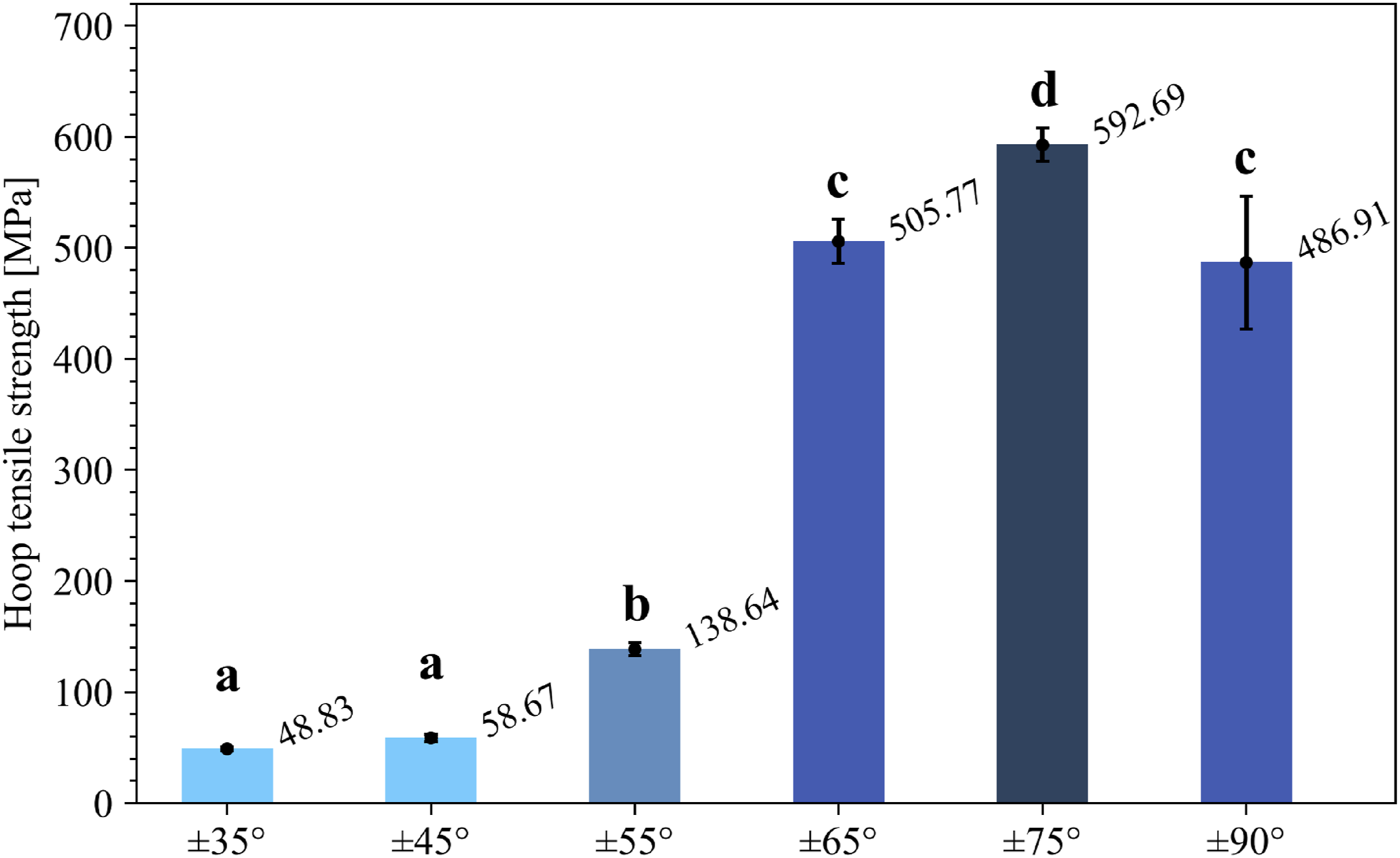
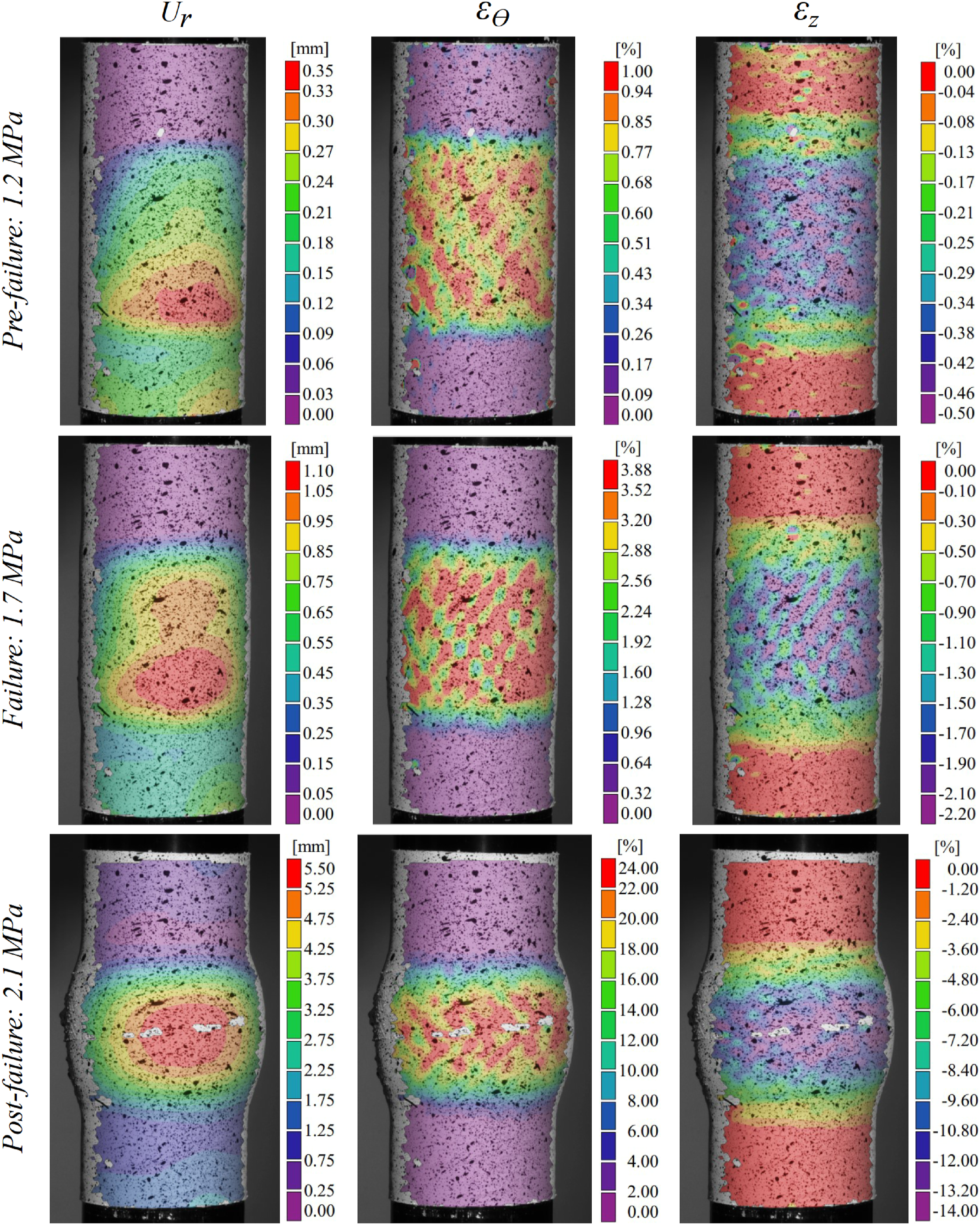
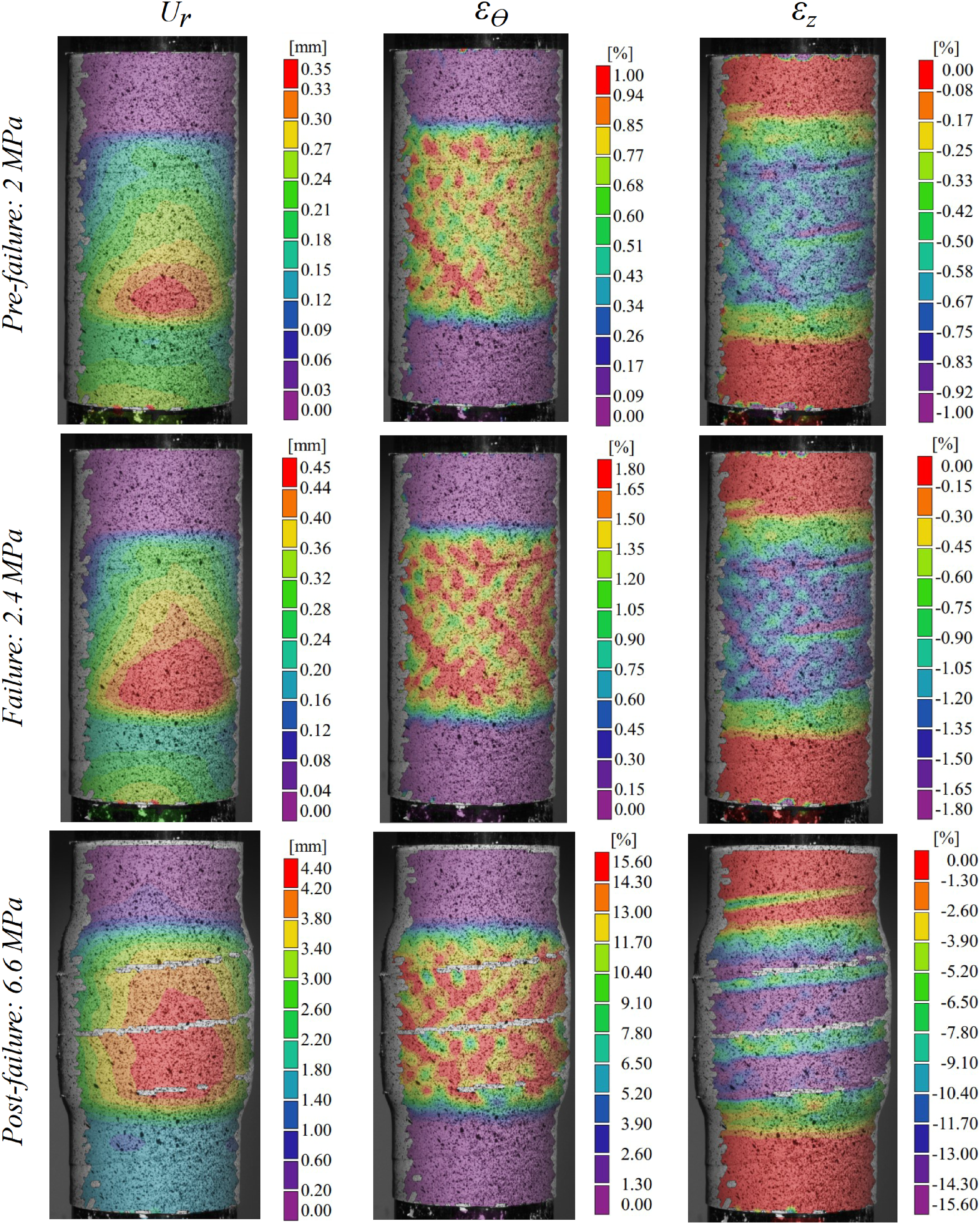
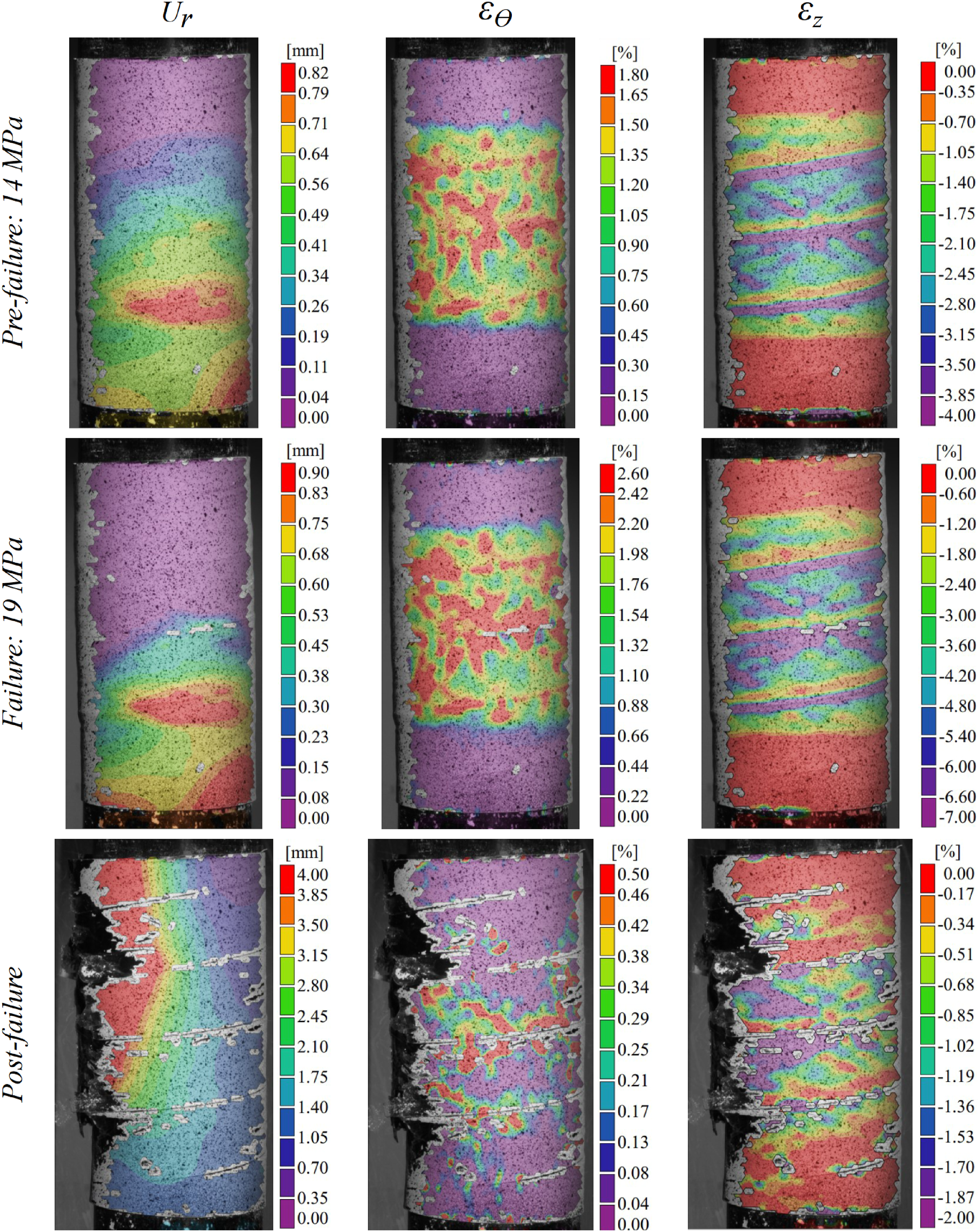
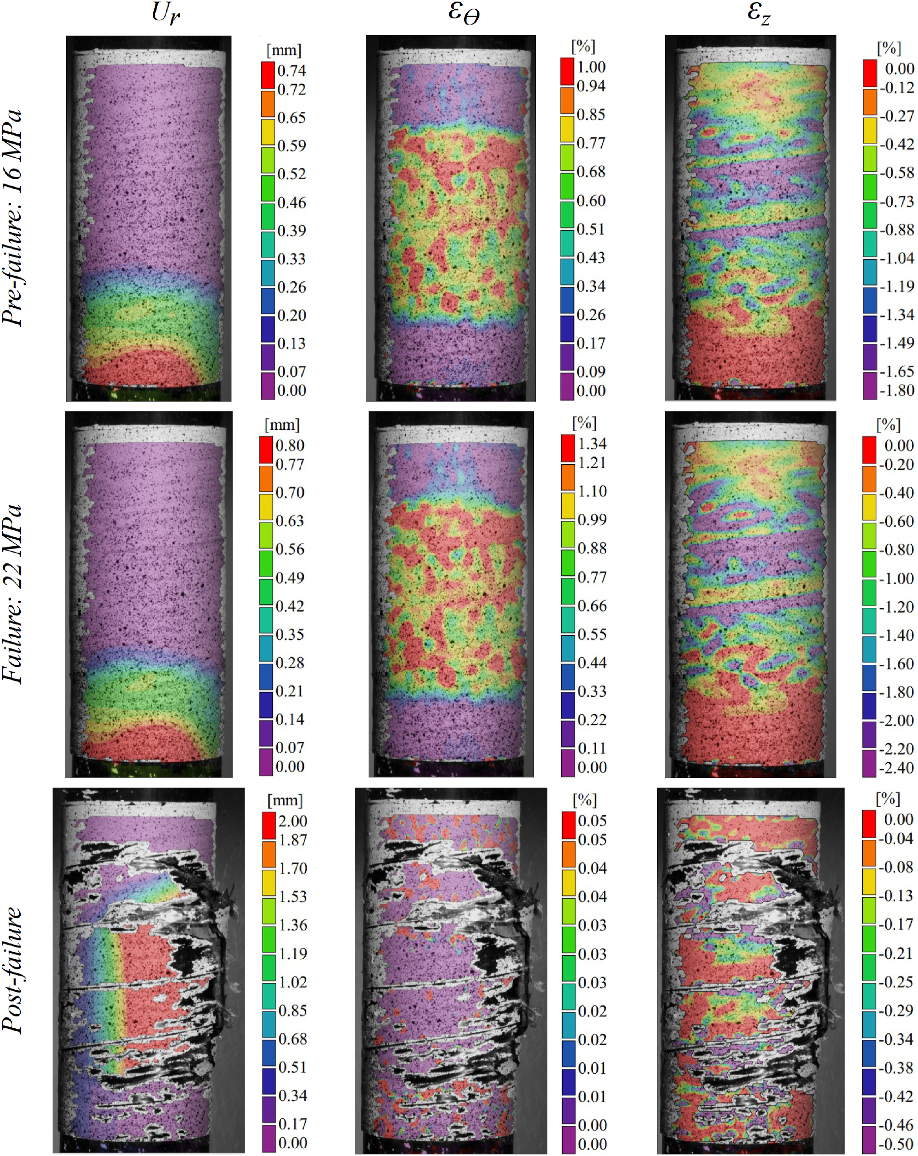
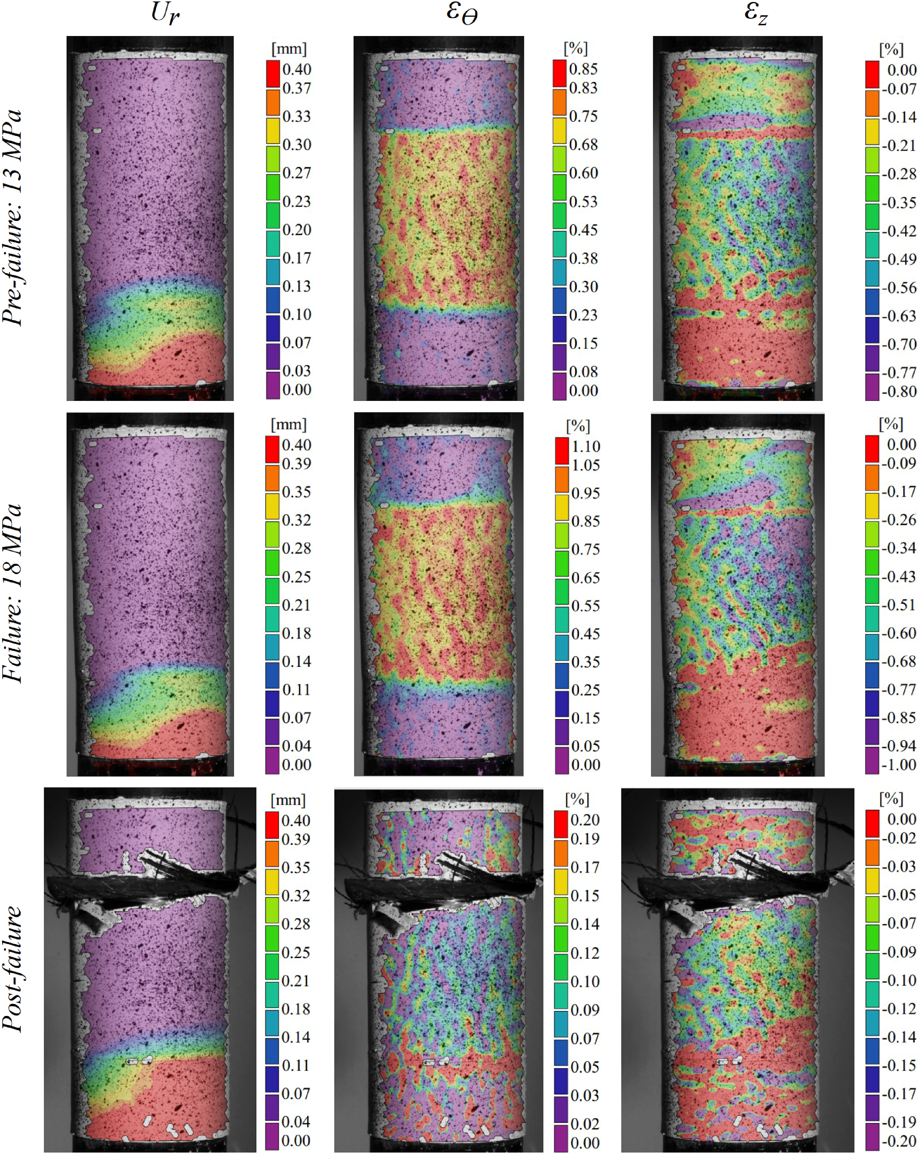
The radial displacement ( Pressure × strain for cylinders wound at (a) ±35°, (b) ±45°, (c) ±55°, (d) ±65°, (e) ±75°, and (f) ±90°. The DIC results for the ±35° cylinders: radial displacement The DIC results for the ±45° cylinders: radial displacement The DIC results for the ±55° cylinders: radial displacement The DIC results for the ±65° cylinders: radial displacement The DIC results for the ±75° cylinders: radial displacement The DIC results for the ±90° cylinders: radial displacement 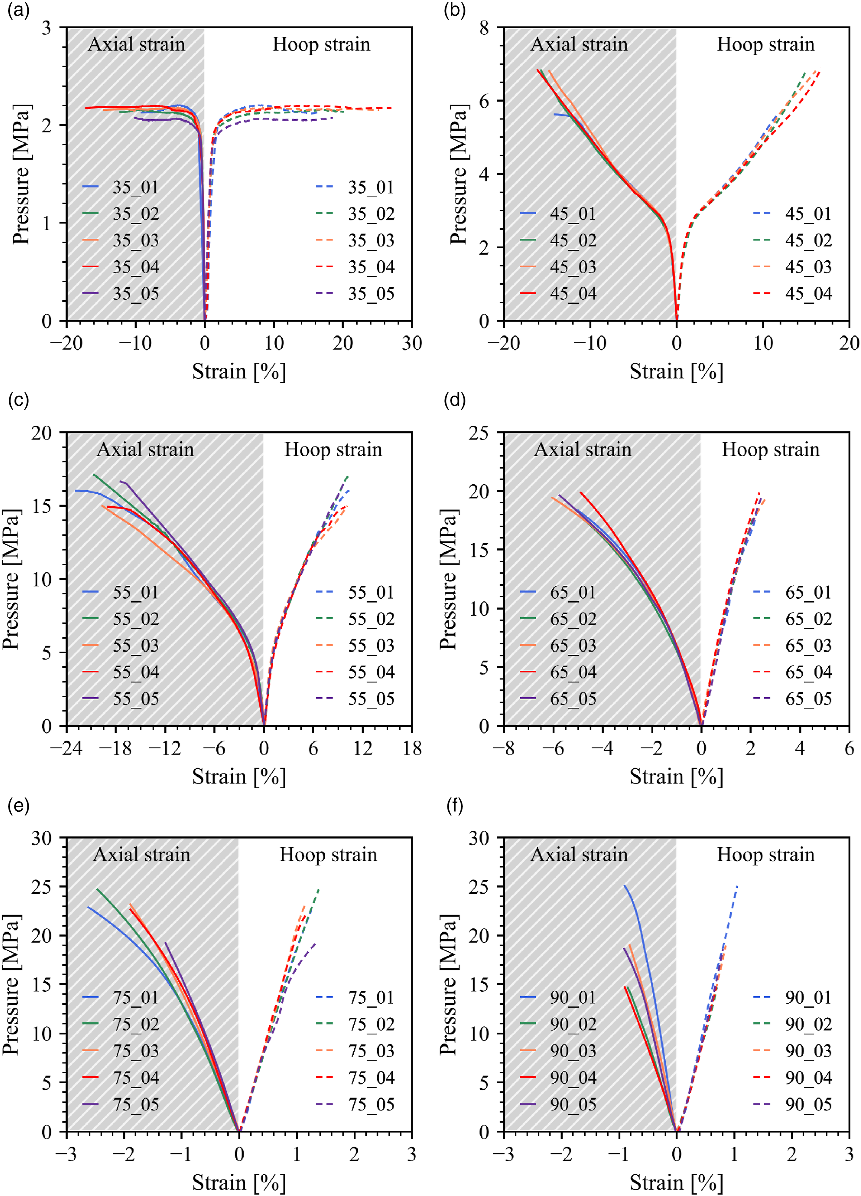
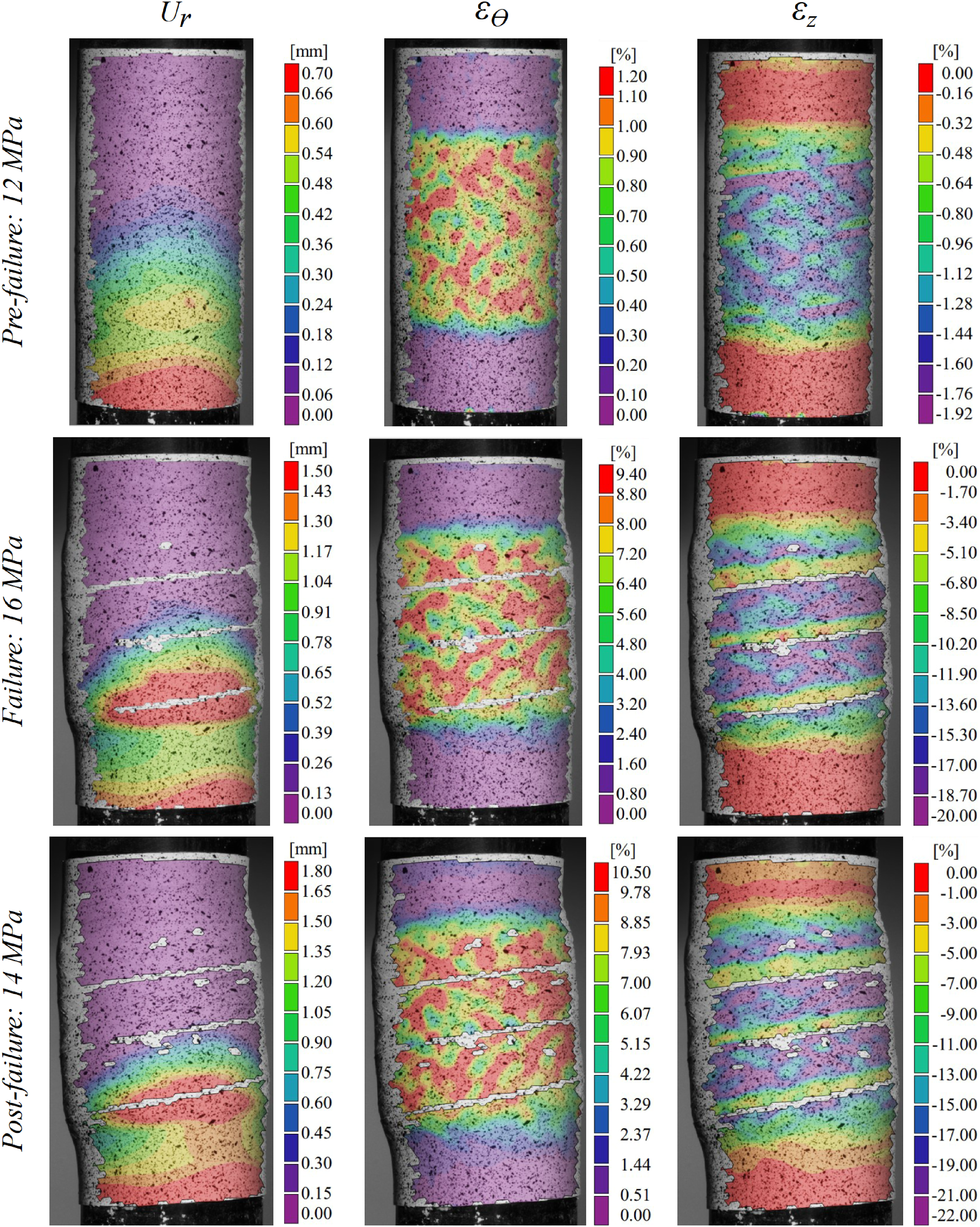
Cylinders wound at ±35°, ±45°, and ±55° do not undergo burst failure. Instead, large nonlinear deformations are observed in both hoop and axial directions. This behaviour is explained by Evans and Gibson. 50 When the initial fibre angle deviates from the stable one, the application of strain induces fibre rotation, resulting in nonlinear stress–strain relationships. As the matrix fails, the effective stiffness of the composite reduces, allowing the fibres to rotate with small increments of pressure and increasing strains until they reach a stable angle at which they can withstand the load without strain-induced rotation. The proportional limit of these cylindrical shells is determined by the intersection point between the pressure × hoop strain curve and a line parallel to the linear response, which is horizontally offset by 0.25% in hoop strain. This intersection of each curve identifies the end of the linear behaviour.
For the ±35° cylinder, this point is around 1.8 MPa of pressure, with 1.2% and −0.6% of the hoop and axial strains, respectively (a hoop-to-axial strain ratio of 2:1). In this case, the end of the linear regime also means the structural failure of the cylinder, as there is practically no increase in load for higher strains. Despite the pronounced bulging experienced by the cylinder, as seen in Figure 7, no visible damage is observed in the fibre tows.
The end of the linear regime for cylinders wound at ±45° occurs at a slightly higher pressure (2.2 MPa) than those at ±35°. In contrast to the previous case, residual strength is still observed in the nonlinear regime. However, strains propagate rapidly with small pressure increments, defining a potentially hazardous operating range. Therefore, structural failure is also linked to a significant reduction in stiffness after the end of the linear-elastic regime. Hoop and axial deformations occur in a more balanced manner, with magnitudes around 1% in each direction, resulting in a more uniform expansion along the pressurised region, as depicted in Figure 8. Once again, despite the significant rotation of the fibre tows, no associated macroscopic major damage is identified.
The ±55° winding angle is the recommended angle to withstand internal pressurisation in closed-end vessels, where the walls are subjected to a 2:1 hoop-to-axial stress ratio. However, for the proposed test setup, consisting of cylinders with open and unconstrained ends, the stress state is different, with hoop stress being the highest and the others negligible in comparison. It is interesting to note that the strains resulting from pressurisation follow an approximate 1:2 ratio in the hoop-to-axial direction. The proportional limit is reached at pressures around 5.2 MPa. Nonetheless, there is a significant remaining strength where the effective stiffness decreases with the continuous increase in pressure up to ca. 16 MPa. In this process, progressive failure due to matrix shear dominates, 51 resulting in a small lateral displacement of the specimen during the test (Figure 9). Analyses of the measured strain fields for these three angles align well with the findings presented by Spencer and Hull. 52
Filament-wound shells with angles of ±65° (Figure 10) and ±75° (Figure 11) experience burst failure, unlike the previous ones. In both cases, small strains are recorded in the hoop direction before the abrupt collapse of the cylinder walls, highlighting the better performance of the reinforcing fibres oriented at these angles. Larger strains are observed in the axial direction, implying shrinking of the cylinders. Deviations from linearity are also more pronounced in the axial direction. The cylinders wound at ±75° achieve the highest capacity to withstand internal pressure, followed by the ±65° sample.
Cylinders wound at ±90° do not form a mosaic pattern. The failure pressure for this winding angle falls between those observed for the ±55° and ±65° angles. However, the failure mode is entirely different from the other tested cylinders. It occurs along a circumferential line parallel to the fibre tow at the pressurised end of the cylinder. In this region, bending stresses in the axial direction are non-negligible, as indicated by the axial strain gradient in Figure 12. The difference in terms of fibre architecture, lacking interweaving regions, is detrimental to the hoop pressure ability of the cylinders. 53 Similar results regarding pressure capacity variation with the winding angle were reported by Martins et al. 29
Conclusions
This paper explores an alternative laboratory-scale test method to conventional hydrostatic pressure tests and tests based on ring specimens for filament-wound cylindrical shells. The featured test proved effective for several winding angles and, compared to hydrostatic tests, show advantages like good loading control, easy assembly, reduced time and costs, improved safety, and the possibility to use DIC for monitoring strain and displacement fields of the specimens. Also, considering that it allows the evaluation of cylinders with helical windings, the proposed test does not have that limitation faced by ring-based tests.
The hoop stiffness of the cylinders increased with the winding angle up to ±90° (hoop winding). The load-carrying ability increased with the winding angle up to ±75°. Specimens wound at ±35°, ±45°, and ±55° angles exhibited matrix-dominant failure, while those wound at ±65°, ±75°, and ±90° showed abrupt brittle failure. The cylinder with hoop-oriented winding, nevertheless, failed along a circumferential line parallel to the fibre tow at the end of the pressurised region, where bending stresses in the axial direction are non-negligible.
Footnotes
Declaration of conflicting interests
The author(s) declared no potential conflicts of interest with respect to the research, authorship, and/or publication of this article.
Funding
The author(s) disclosed receipt of the following financial support for the research, authorship, and/or publication of this article: CAPES/DAAD (PROBRAL project Nos. 88881.198774/2018-01 and 57447163), FAPERGS (Inova Clusters Tecnológicos project No. 22/2551-0000839-9), and CNPq/EQUINOR (project No. 440115/2019-1). HA is supported by the Royal Academy of Engineering, UK, under the Research Fellowship scheme (Grant No. RF/201920/19/150).
Data Availability Statement
Data available on request from the authors.