
Abstract
Carbon fibre reinforced polymer (CFRP) laminates nano-enhanced with carbon nanofibers (CNFs): 0.75 wt% and 0.5 wt% of epoxies Sicomin and Ebalta, respectively, were manufactured and their static and viscoelastic behaviour analyzed. After 180 min, the bending stress decreases and creep displacement increases over time, with Ebalta nano-enhanced resin laminates with CNFs showing the best results. A strong dependence of creep behaviour and stress relaxation is obtained with the applied stress level. The results show that laminates produced with pure Sicomin resin increased creep displacement by 1%, for a bending stress of 200 MPa, and 2 times greater for the bending stress of 700 MPa. The viscoelastic behaviour of CFRP composites nano-enhanced with CNFs was accurately predicted by the Kohlrausch-Williams-Watts (KWW) model and Findley power law.
Keywords
Introduction
Epoxy-based composites, such as, carbon fibre reinforced polymers (CFRP) have been widely applied in aerospace, energy and many other fields where a lightweight material is required, due to their high specific strength and modulus, fatigue resistance, good thermal and electrical conductivities, excellent creep resistance and remarkable design.1–4 However, their outstanding mechanical performance largely depends on the cohesion between the matrix and fibre reinforcement, also an effective nanoscale reinforcement can be provided by the addition of carbon nanofillers.5–7
Extensive research has resulted in remarkable property improvements of carbon nanotubes (CNTs) reinforced epoxy composites. It was noted that as the loading of CNTs increased up to 10 wt%, the failure strength improved slightly. 8 For instance, the addition of up 1 wt% of CNTs, the failure strength of the composites improves 3 times and the Young’s modulus doubled.5,8 Nevertheless, besides the considerable values reported, considering the properties of the CNTs by themselves, the improvements in these properties are lower than expected. Their large surface-to-volume ratio leads to agglomeration due to the strong attraction between CNTs and the large van der Waals forces.9–11 On the other hand, even with the increase of the body weight ratio of CNTs in the polymer matrix, the properties tend to decrease. 12 Another disadvantage is the chemically inert nature of CNTs leading to poor interfacial interactions with epoxy matrix.10,13 High energy input and mechanical dispersion are used with success to improve the dispersion of CNTs. Advances in chemical modification and functionalization of CNTs also improve the surface bonds and facilitate the transfer of stress between the CNTs and the polymer matrix.5,13,14 This improvement was related with C–F covalent, semi-ionic, ionic and van der Waals interactions which brings about enhanced interfacial interactions.10,14 These difficulties are mainly felt in the multi-walled carbon nanotubes (MWCNTs) due to their strong inter-tube interaction and large surface area. 15
The addition of CNTs into an epoxy matrix significantly reduces the creep deformation; as an example, when adding 0.25 wt% of CNTs, a reduction of up to 30% in the creep strain is observed. However, the creep improvement is only evident for small levels of reinforcement. When the nanotube fraction is increased to more than 1% by weight, the creep performance deteriorates rapidly due to poor quality dispersion of the nanotubes in the epoxy resin. 16
In previous works, 17 it was verified that the use of carbon nanofibers (CNFs) benefits the mechanical properties of the epoxy resins. The improvements are mainly attributed to enhanced interfacial properties.17–19 Applying a simple manufacturing process, that can be implemented in the automotive, aeronautics, military and green energy production industries, is intended to optimize CFRP carbon fabric with an ideal percentage of CNFs to respond to new structural requirements. These functions are often related to load bearing and dynamic loading applications to increase the durability of this hierarchical laminate and predict the response in viscoelasticity and temperature dependence; therefore, it is very important to evaluate the response to stress relaxation and creep strength.20–22
In this work, the static bending response of several laminates involving matrices with different viscosities (285 ± 60 mPa×s for Sicomin resin and 250 ± 50 mPa×s for Ebalta resin) and reinforced with different CNFs contents (0.25, 0.5; 0.75 and 1 wt% of CNFs) was analyzed. Subsequently, considering the few studies found in the literature, a study will be carried out to evaluate the benefits of nano-reinforcements on the viscoelastic response of laminated composites. For this purpose, only the laminates involving the neat resin (resins without CNFs) and those containing the CNFs content that maximized the static properties will be subjected to stress relaxation and creep tests for different periods of time (3 h and 100 h). Finally, based on the experimental results for 3 h, the analytical Kohlrausch-Williams-Watts (KWW) and Findley models will be fitted and subsequently validated for 100 h by comparability with those obtained experimentally.
Materials and methods
Composite laminates involving two different resins were studied in this work. For this purpose, an epoxy resin SR 8100 with hardener SD 8824, both supplied by Sicomin, and an epoxy resin AH 150 with hardener IP 430, both supplied by Ebalta, were combined with eight layers of bidirectional carbon fibre 195-1000P (195 g/m2) using the hand lay-up technique. The plain weave used consists of carbon fibres at 0 and 90° with 98 ± 4% g/m2 in each direction, and more details about the resins can be found in previous work. 23 All layers were placed in the same direction to obtain plates with overall dimensions of 330 × 330 × t (mm), where t is the thickness of the laminates after curing (t = 1.5 ± 0.1 mm for laminates with Sicomin resin and 1.9 ± 0.1 for the Ebalta resin). Subsequently, they were placed inside a vacuum bag and subjected to a compressive load of 2.5 kN load to obtain a constant fibre volume fraction and uniform laminate thickness. Finally, according to the supplier´s guidelines, the laminates produced with the Sicomin resin were cured at room temperature for 24 h and subjected to a post-cure at 40°C for 24 h, while the laminates involving the Ebalta resin were cured at room temperature for 48 h and subjected to a post-cure at 80°C for 5 h. In both composites, the bag remained attached to a vacuum pump for the first 4 h to eliminate any air bubbles.
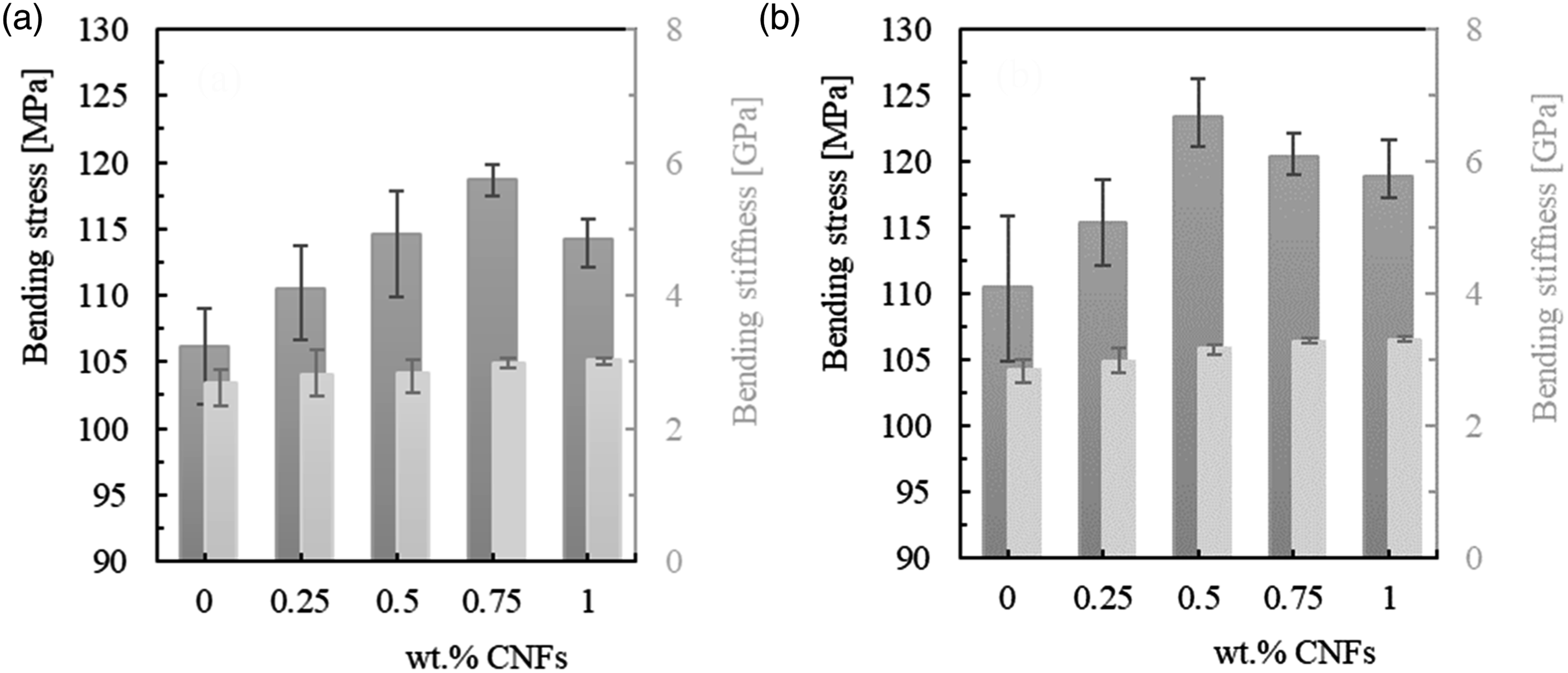
To assess the benefits of CNFs on the bending properties of the composite laminates, these resins were nano-enhanced with 0.25%, 0.5%; 0.75% and 1% by weight of CNFs. These nanofiber contents were also used in a previous study to evaluate the value that maximized the static properties of each resin,
23
and the results obtained are summarized in Figure 1. For this purpose, the carbon nanofibers used were supplied by Sigma-Aldrich which, according to the manufacturer's datasheet, are pyrolytically stripped (conical) with an average diameter of 130 nm, length between 20 and 200 μm and average specific surface area of 54 m2/g. Their mixture into the resin was conducted using a high-speed shear mixer at 1000 r/min, at room temperature for 3 h, followed by 10 min at 150 r/min for the hardener to disperse into the system. Simultaneously, this procedure was combined with an ultrasonic temperature-controlled bath (with a frequency of 40 kHz) to improve the dispersion of the nanofibers. Finally, the system was degassed in a vacuum oven. This optimized methodology is conveniently reported in the work of Santos et al.
19
After ensuring good dispersion of the CNFs into the resins, these systems (resin + CNFs) were combined with the carbon fibres using the procedure described above (similar to that used with the neat resins to produce carbon/epoxy laminates). Effect of CNFs content on bending stress and bending stiffness for the: (a) Sicomin resin; (b) Ebalta resin (detailed information can found in previous work
23
).
The samples used in this study were cut from those plates with the dimensions 80 × 10 × t (mm) and tested in the bending mode (see Figure 2). Regarding the three-point bending (3PB) tests, they were carried out at room temperature in a Shimadzu universal testing machine, model Autograph AGS-X, with a 10 kN load cell, at a displacement rate of 2 mm/min and, for each condition, at least five specimens were tested in accordance with the European Standard EN ISO 178:2003. The span used for all configurations was 40 mm. These tests were also useful for selecting the values used in the creep and stress relaxation tests to ensure that they were performed within the elastic regime of the composites. (a) Geometry of the specimens; (b) Schematic view of the three-point bending apparatus. All dimensions in mm.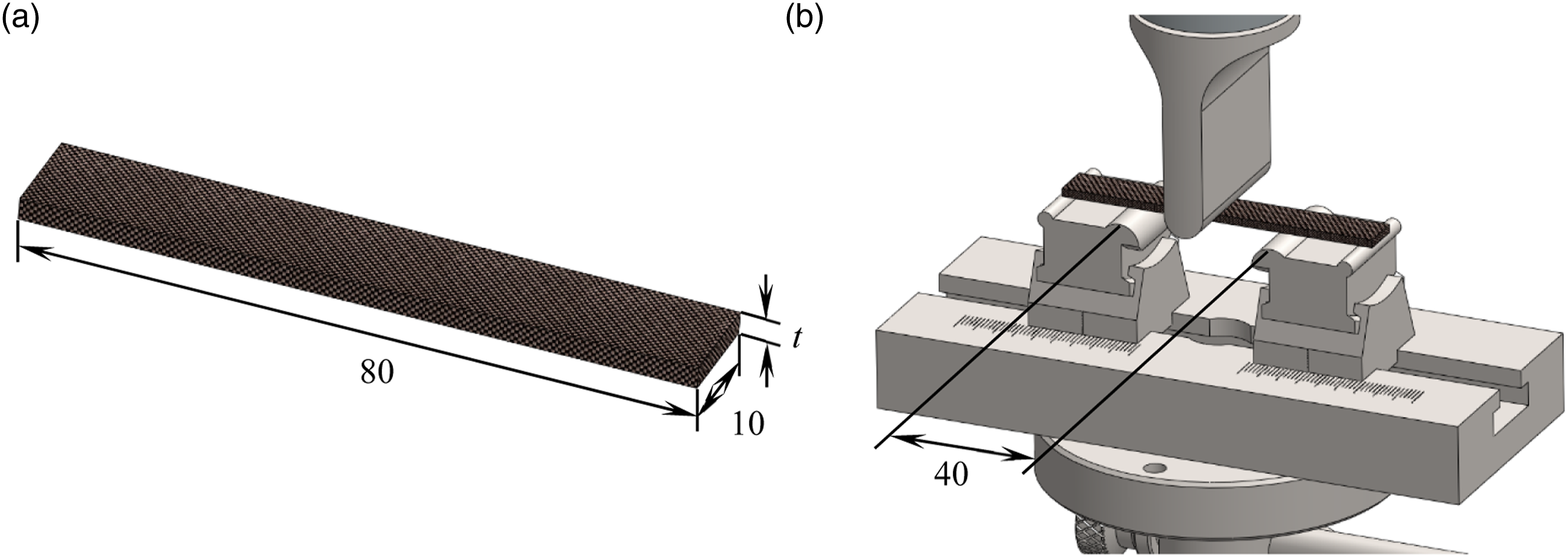
The same equipment was used to perform the stress relaxation and creep tests at room temperature and with samples similar to those described above. Note that these tests were only performed with laminates whose CNFs content maximized the static properties. Therefore, regarding the stress relaxation tests and according to the recommendations described in ASTM E328-13, a fixed strain was applied (corresponding to 200 MPa, 450 MPa and 700 MPa for composites involving the Sicomin resin, and 190 MPa, 380 MPa and 570 MPa for those involving the Ebalta resin) and the stress recorded during the loading time of 3 h. In terms of creep tests, they were carried out according to the recommendations described in ASTM D2990-09 standard. In this case, a fixed bending stress was applied (with values similar to those previously reported), and the displacement recorded during 3 h of loading. A 40 mm span was used in all the tests and at least three specimens were tested.
Finally, for the execution of this work plan about 40 days elapsed between production and the beginning of the last test, but to guarantee that all samples were tested under the same conditions, they were stored in controlled environmental conditions (no sun exposure, room temperature (22°C–24°C) and relative humidity between 55% and 60%). Subsequently, during testing, all specimens were also subjected to the same laboratory conditions (room temperature (22°C–24°C) and relative humidity between 55% and 60%).
Results
Static characterization
From the static tests performed to evaluate the CNFs content to maximize the bending properties, Figure 3 shows the typical curves obtained and which are representative of all others obtained in this study. Bending stress-strain curves for composite laminates with: (a) Sicomin matrix; (b) Ebalta matrix.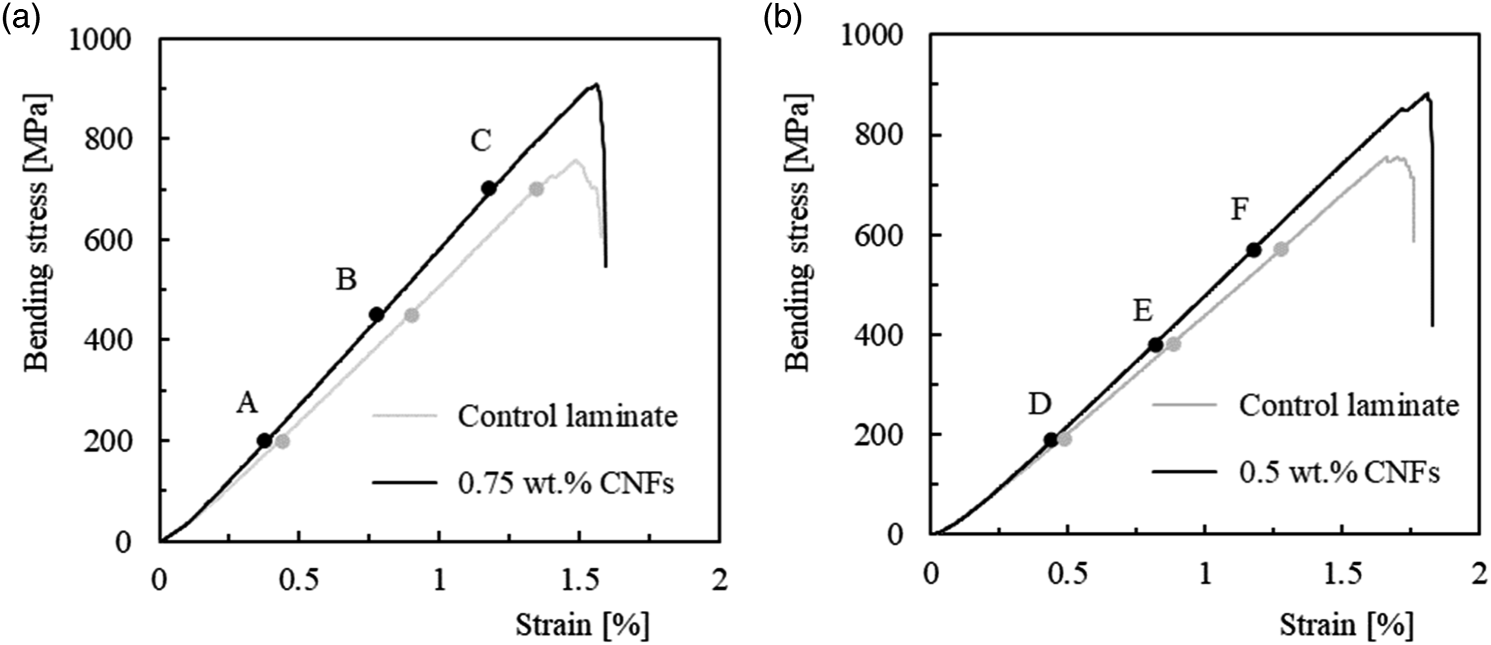
It is possible to observe that both composites show a quasi-brittle behaviour, where the bending stress increases linearly with the strain, culminating in a sudden drop after reaching the peak stress. Figure 4 shows the damage mechanism common to all composites, where it is possible to observe the existence of broken fibres under compression, accompanied by small delamination around them. Note that at the top of the image, due to the applied loading, there is a region subject to compression while the bottom is in tensile. According to the literature, this damage mechanism is typical of composites involving carbon fibres,17,24 due to their low compressive strength, in addition to high compressive stress concentration in the pin load contact region.
24
Typical failure damage observed for control laminates.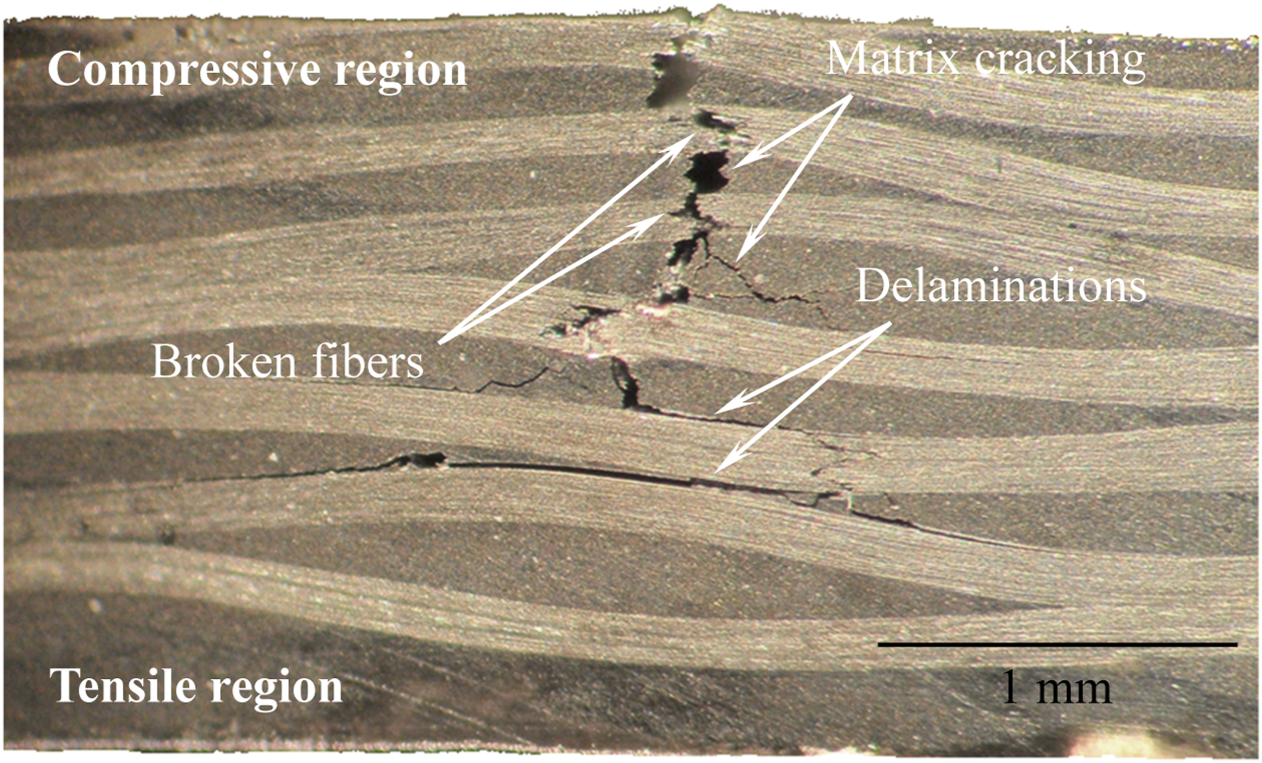
From these curves (Figure 3), the bending properties shown in Figure 5 are obtained. In terms of bending strength, for example, average values of 752.2 ± 15.0 MPa and 756.2 ± 13.9 MPa were found for laminates with neat Sicomin and Ebalta resins (resins without CNFs), respectively. Furthermore, the bending strength was maximized when the resins were filled with 0.75 wt% and 0.5 wt% of CNFs, respectively, and these values were about 20.4% (from 752.2 MPa to 905.3 MPa) and 12.5% (from 756.2 MPa to 850.9 MPa) higher than those obtained with the control laminates. Bending stress and bending stiffness for laminates produced with different wt.% CNFs for: (a) Sicomin resin; (b) Ebalta resin.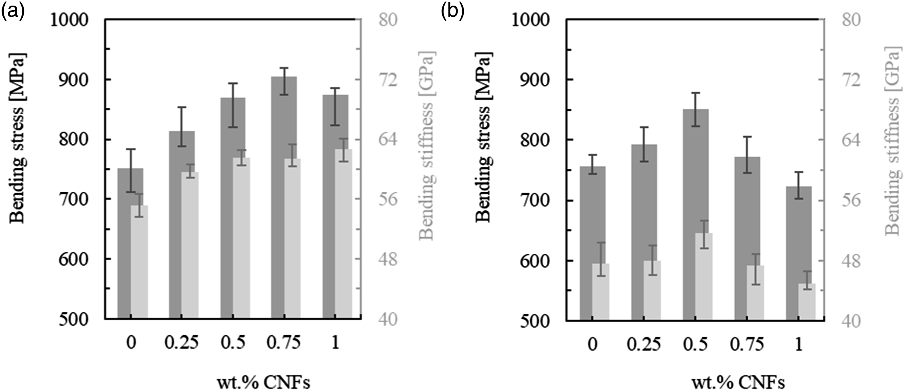
These results also highlight that the bending strength was maximized for the same CNFs content observed in the previous study (see Figure 1) involving these resins and the same nano-reinforcements. 23 In the previous mentioned study, it was observed that higher values of CNFs promoted agglomerates, which drastically affected the mechanical properties. Moreover, the difference in viscosities (250 ± 50 mPa.s for the Ebalta resin and 390 mPa.s for the Sicomin resin) was not relevant, given the higher physicochemical compatibility between Sicomin resin and CNFs. 23
In terms of creep and stress relaxation tests, these were performed involving control laminates (with neat resins) and laminates whose CNFs content maximized the bending strength (0.75 wt% and 0.5 wt% of CNFs for Sicomin and Ebalta resins, respectively). Figure 3 also shows the different bending stress levels used in the creep and stress relaxation tests. To ensure that all tests were performed within the elastic regime, stresses of 200 MPa (A), 450 MPa (B) and 700 MPa (C) were selected for laminates involving the Sicomin resin and for the Ebalta resin 190 MPa (D), 380 MPa (E) and 570 MPa (F). These values are close to 25%, 50% and 75% of the maximum bending stress for each laminate, respectively.
Stress relaxation
According to the bibliography, stress relaxation in polymer systems is based on physical and/or chemical processes. While molecular rearrangements that require little formation or rupture of primary bonds are expected in the first case, chain scission, crosslink scission or crosslink formation occur in the second case.25–27 However, when the polymers are reinforced with fibres, these hinder the molecular flow and delay the relaxation process, as shown in Figure 6. Stress relaxation curves obtained with samples produced with neat Ebalta resin (obtained from Ref.
28
) and carbon/epoxy laminates produced with neat Ebalta resin.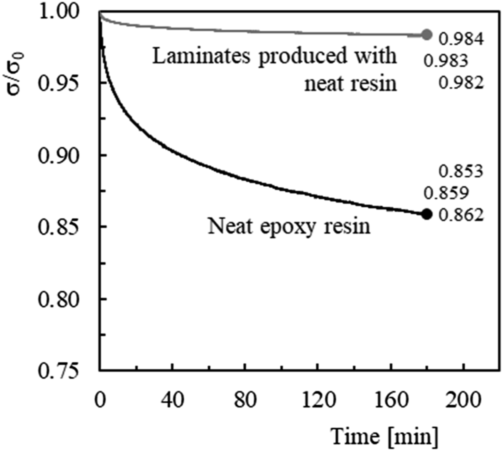
This figure depicts the benefits obtained with the introduction of carbon fibres, where
It is possible to observe that the epoxy resin relaxes much more than the composite, showing that the latter is 8.3 times less sensitive than the resin to the stress relaxation phenomenon. The fibres hinder the molecular flow and delay the relaxation process, although, the interface properties are very relevant because relaxation processes can occur due to the breaking of bonds and respective propagation. 22 Therefore, in composites, the stress relaxation phenomenon is a consequence of two mechanisms: matrix phase relaxation and fibre/matrix debonding zones with the respective crack propagation.27,29
Regarding the benefits obtained with resins reinforced with CNFs, Figure 7 presents the average bending stress versus time curves for all laminates and bending strains. Again, σ represents the bending stress at any given moment of the test and Stress relaxation curves for all bending strains and laminates with: (a) Neat Sicomin resin; (b) Neat Ebalta resin; (c) Sicomin resin enhanced with 0.75 wt% of CNFs; (d) Ebalta resin enhanced with 0.5 wt% of CNFs.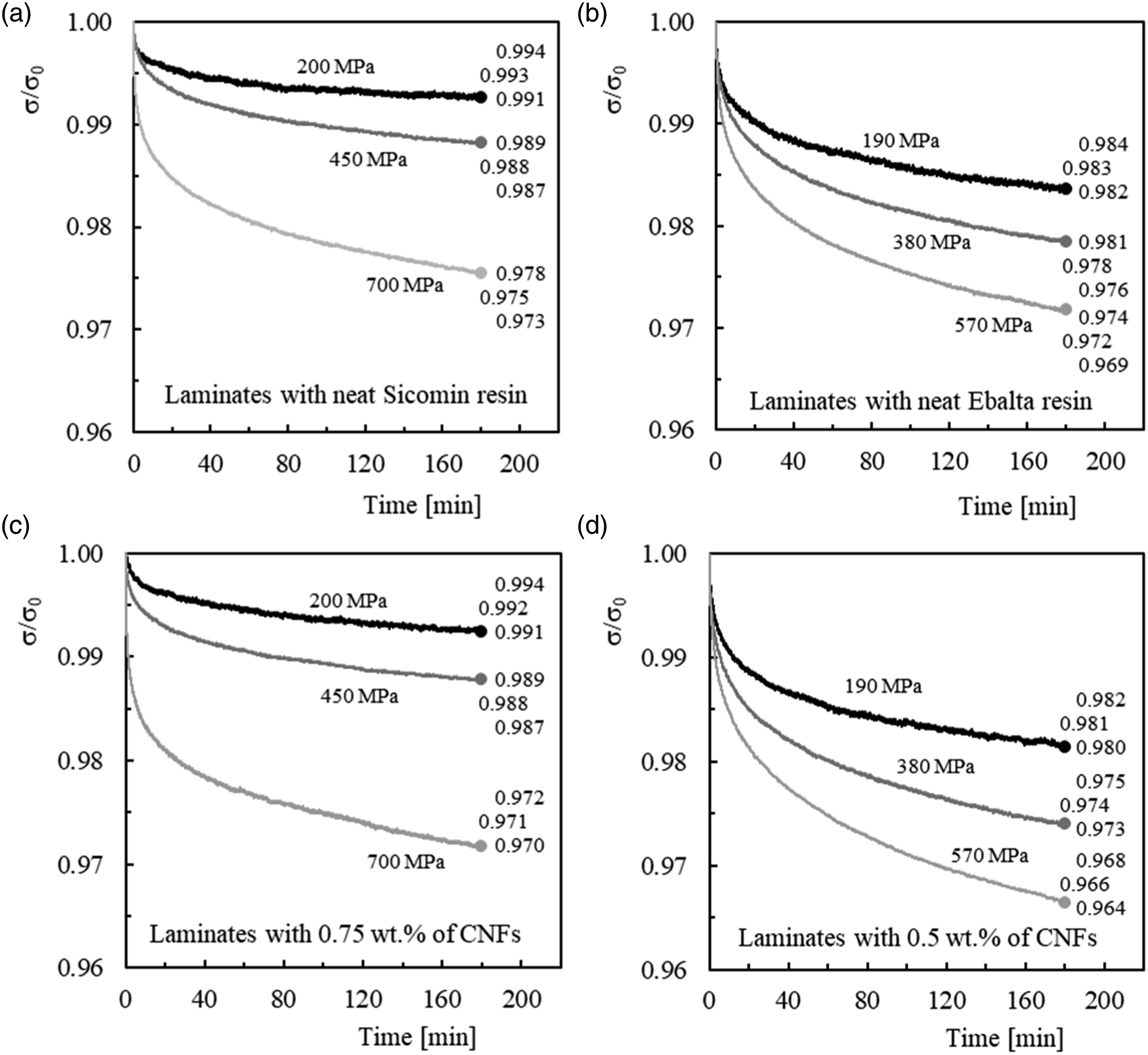
Regardless of resins and bending strain levels, it is possible to observe a decrease in bending stress with time. The bending stress never reached a constant value because this study focuses on short-term tests. In fact, they are an easy, fast and reliable method to predict the behaviour for longer periods of time.29,30 It is also noticed that higher bending strains promote higher stress relaxation values. Referring only to the values corresponding to laminates produced with neat Sicomin resin, the bending stress decreases by only 0.8% for the bending stress of 200 MPa, but this value is already 2.9% for the bending stress of 700 MPa (3.6 times higher). However, this evidence also extends to the other configurations analyzed. What´s more, as reported in literature,29,31–34 it is also noted that there is an initial period in which the decrease in bending stress is higher compared to the remaining time. For example, considering laminates produced with Sicomin resin nano-enhanced by 0.75 wt% of CNFs (Figure 7(c)), there is a decrease around 0.4%, 0.8% and 2.0% in the first 30 min for the bending strains corresponding to bending stresses of 200 MPa, 450 MPa and 700 MPa, respectively, while the remaining decrease (between 30 and 180 min) is only about 0.3%, 0.4% and 0.8%, respectively. Again, this evidence also extends to all configurations analyzed. Therefore, as previously reported, the stress relaxation response is due to the matrix phase relaxation and fibre/matrix debonding zones with the respective crack propagation.27,29 However, Figure 7 also shows that laminates with Ebalta resin show higher stress relaxation values than those observed for laminates produced with Sicomin resin. As reported by Santos et al., 23 this can be attributed to their different interfacial adhesion and different physical interactions resulting from the non-identical polarity of both resins. On the other hand, according to Vlasveld et al. 35 and Jian and Lau, 36 the deformation process in polymers under load is strongly dependent on the mobility of the chains and not only dependent on temperature. Finally, the CNFs effect is also shown in Figure 7, and considering the expected experimental variation and measurement errors, the almost identical results that are observed for the same resin typology reveal that CNFs do not have a deleterious effect on the relaxation behaviour of the laminates. This denotes that the dispersed nanoparticles bind to the matrix via interphases, bridging segments and junctions to support the load, but are not in sufficient quantity to promote immobility of the polymer chains.37–39 Furthermore, it should also be emphasized that the bending stresses used in these tests are the same for each type of resin, giving laminates with nano-reinforced resins a slight advantage due to their higher bending strength compared to laminates with neat resin.
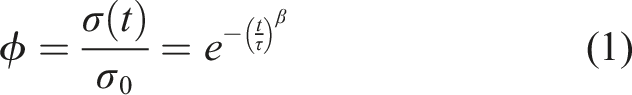
Literature presents several models to predict the behaviour of stress relaxation based on results obtained in short-term tests. In this context, Kohlrausch-Williams-Watts model (KWW) is preferable to those based on spring-dashpot systems, because it promotes more accurate predictions.
40
Although the constants involved in this model have no physical significance, it fits the experimental curves quite accurately and can be used to predict the stress relaxation response for longer lives.29,32,33,41 According to this model, the relaxation function
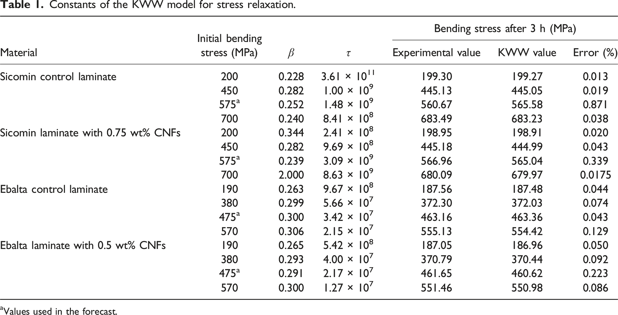
The comparison between the experimental and theoretical curves is shown in Figure 8 for the laminate produced with Ebalta resin reinforced with 0.5 wt% CNFs. However, this comparison is representative of all conditions analyzed, where the final bands represent the maximum and minimum values obtained in each condition analyzed. Table 1 summarizes all constants of the KWW model and respective error in relation to the experimental results, while Table 2 presents the constants of the equations that fit the KWW model (Figure 8(b)). In detail, Figure 8(a) shows the good accuracy obtained with this model, in which the error between the theoretical and experimental curves is only 0.05% after 180 min of testing. However, this evidence can be generalized to all conditions and materials because, as shown in Table 1, the maximum error obtained with this model is less than 0.13%. In terms of prediction, Reis et al.29,32,41 suggested that when the parameters of the KWW model are presented against the applied stresses, it is possible to fit a function capable of being used as a prediction tool to predict the stress relaxation response for any bending displacement. (a) Comparison between experimental and theoretical curves for laminates with Ebalta resin reinforced with 0.5 wt% CNFs and bending stress of 190 MPa; (b) KWW parameters versus bending stress for laminates with Ebalta resin reinforced with 0.5 wt% CNFs. Constants of the KWW model for stress relaxation. aValues used in the forecast. Parameters of the equations that fit the KWW model. R2 = Squared correlation coefficient.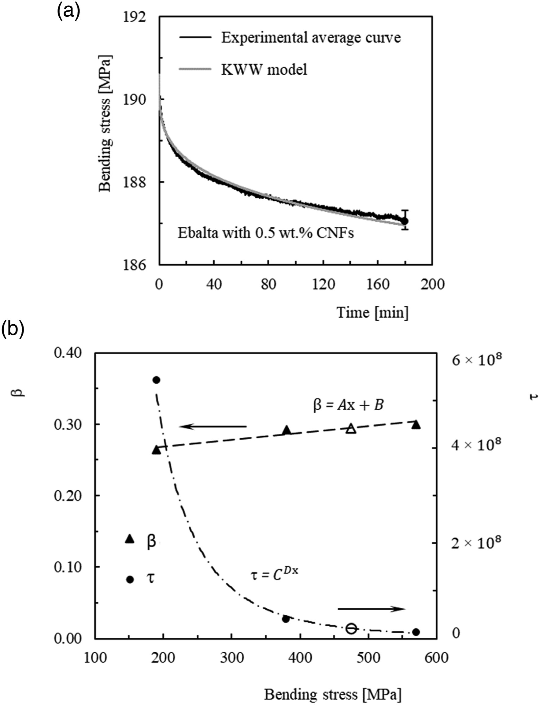
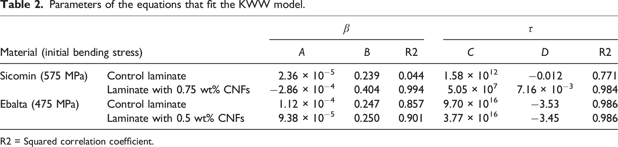
In this context, Figure 8(b) illustrates this methodology for laminates produced with Ebalta resin reinforced with 0.5 wt% of CNFs, as well as the bending stress value of 475 MPa (corresponding to the white marks: β = 0.291 and τ = 2.17 × 10⁷) that will be used for validation. This procedure was applied to all laminates and the values of the respective equations used to predict the stress relaxation response are shown in Table 2. Therefore, considering the values shown in Figure 8(b) (β = 0.291 and τ = 2.17 × 10⁷), it is possible to conclude that the error obtained with the methodology described above is less than 0.23%. However, when all materials are considered, the maximum error observed is only 0.87%, which reveals the good accuracy of this methodology (see Table 2).
Finally, the ability of this model to predict the structural behaviour for longer periods of time was also analyzed and, for this purpose, the reasonable accuracy obtained is shown in Figure 9 for a bending stress of 475 MPa and 100 h of testing (33.4 times longer than the time used in short-term tests). In this case, the observed error is less than 0.6%, and although the theoretical curves lead to lower values of stress relaxation than those obtained experimentally, they are within the scatter of the experimental results. Therefore, the reasonable accuracy obtained shows that the methodology used to estimate the effect of bending stress on stress relaxation for long periods of time can be used with some confidence. Nonetheless, further studies for other materials and longer periods of time will be needed to confirm the robustness of the model. Comparison between experimental and theoretical curves for 100 h and bending stress of 475 MPa.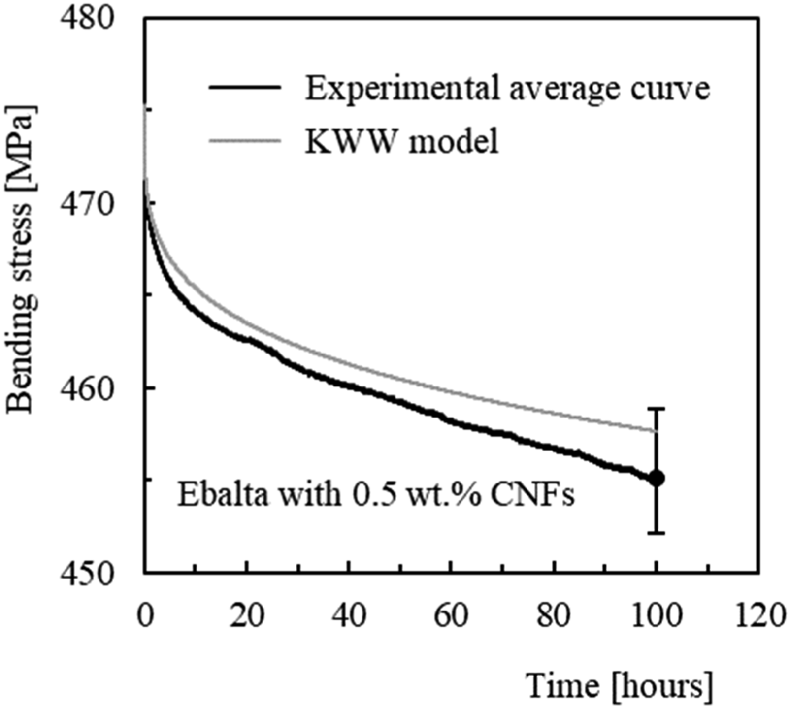
Creep
In terms of creep, this phenomenon in polymers happens even at room temperature and for low stress levels as a consequence of the molecular motion in backbone polymer arrangement.21,42–44 However, as shown in Figure 10, the creep process is delayed by the presence of carbon fibres because the elastic deformation and viscous flow are retarded. Inevitably, the fibre/matrix interface proves to be very important because the bonds’ breakage and their propagation control the creep displacement.6,21 Creep curves obtained with samples produced with neat Ebalta resin (obtained from Ref.
28
) and carbon/epoxy laminates produced with neat Ebalta resin.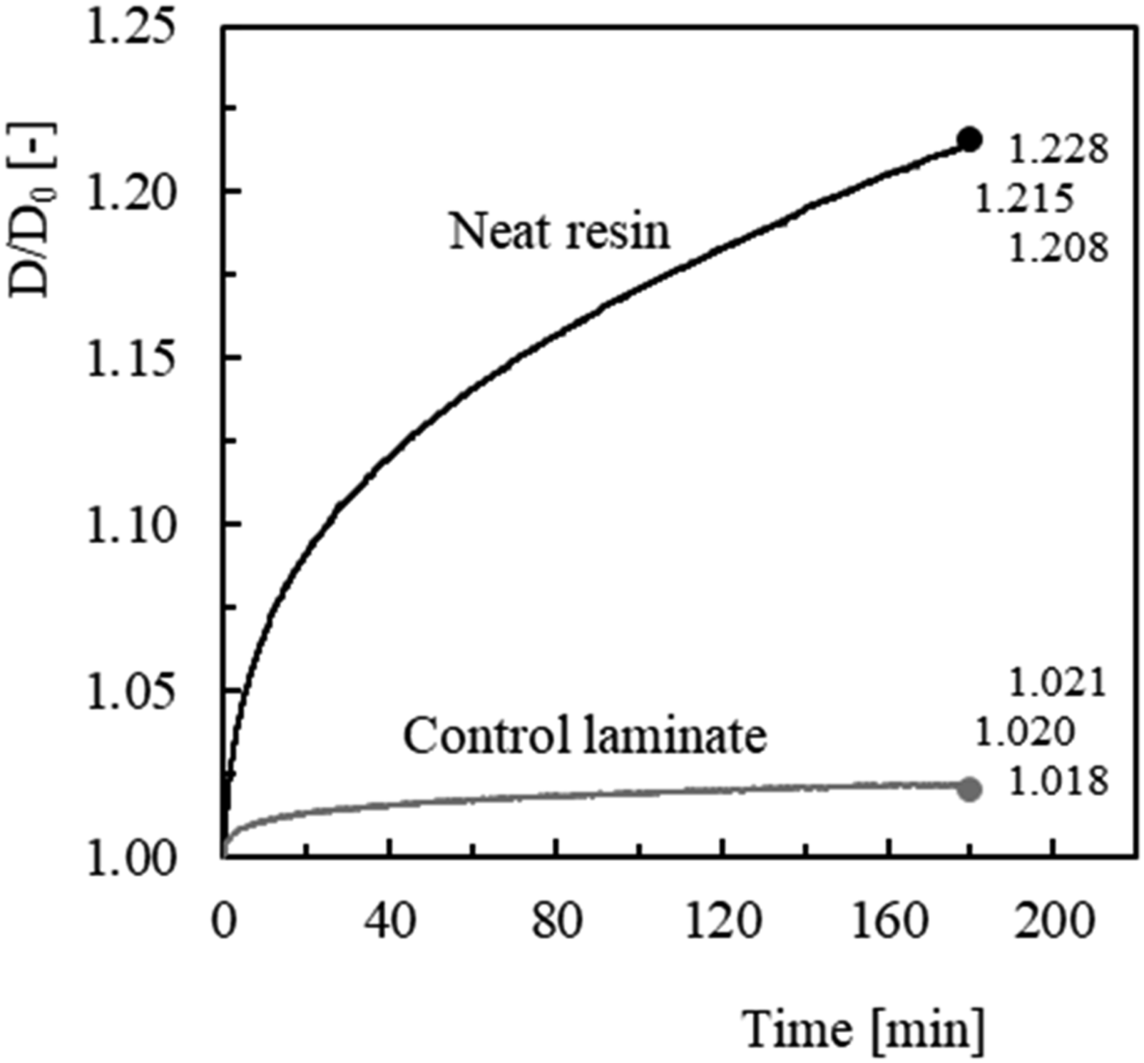
Similar to what was observed for stress relaxation, these curves also show that the resin exhibits a higher creep displacement than the composite. For example, after 180 min, the resin has a creep deformation almost 11 times higher than the composite, which evidences that carbon fibres retard the elastic deformation and the viscous flow of the matrix.6,21
In relation to the benefits obtained with resins reinforced with CNFs, Figure 11 presents the average creep displacement versus time curves for all laminates and bending stresses, where the displacement presented is the displacement at any time of the test (D) divided by its initial value (D0). The values presented for 180 min represent the average value and respective maximum and minimum values observed in each test/condition. For all laminates and bending stresses, it is possible to observe an increase in creep displacement over time. In detail, all curves present an instantaneous displacement, which depends on the stress level, followed by the primary and secondary creep regimes that characterize the typical creep curves. However, for the analyzed conditions, the third regime is expected to occur only for higher bending stresses or longer periods of time. On the other hand, there is a strong dependence of the creep behaviour with the applied stress level. Considering the control laminates produced with neat Sicomin resin, for example, while creep displacement increases around 1% for a bending stress of 200 MPa, this value is about 2 times higher for the bending stress of 700 MPa. These values for laminates produced with Ebalta resin are 2% and 1.4 times higher, respectively, for bending stresses of 190 MPa and 570 MPa. Furthermore, comparing both laminates, the creep displacements are higher for laminates produced with Ebalta resin due to the higher mobility of their polymer chains.35,36 Finally, similar to what was observed in the stress relaxation behaviour, CNFs do not have a noxious effect on the creep behaviour of the laminates when considering the observed experimental variation and no measurement errors occurred. The dispersed CNFs bind to the matrix via interphase, bridging segments and junctions to support the load, but are not sufficient to improve the restriction to slippage, realignment and motion of polymeric chains.37–39 Creep curves for all bending stresses and laminates with: (a) neat Sicomin resin; (b) neat Ebalta resin; (c) Sicomin resin enhanced with 0.75 wt% of CNFs; (d) Ebalta resin enhanced with 0.5 wt% of CNFs.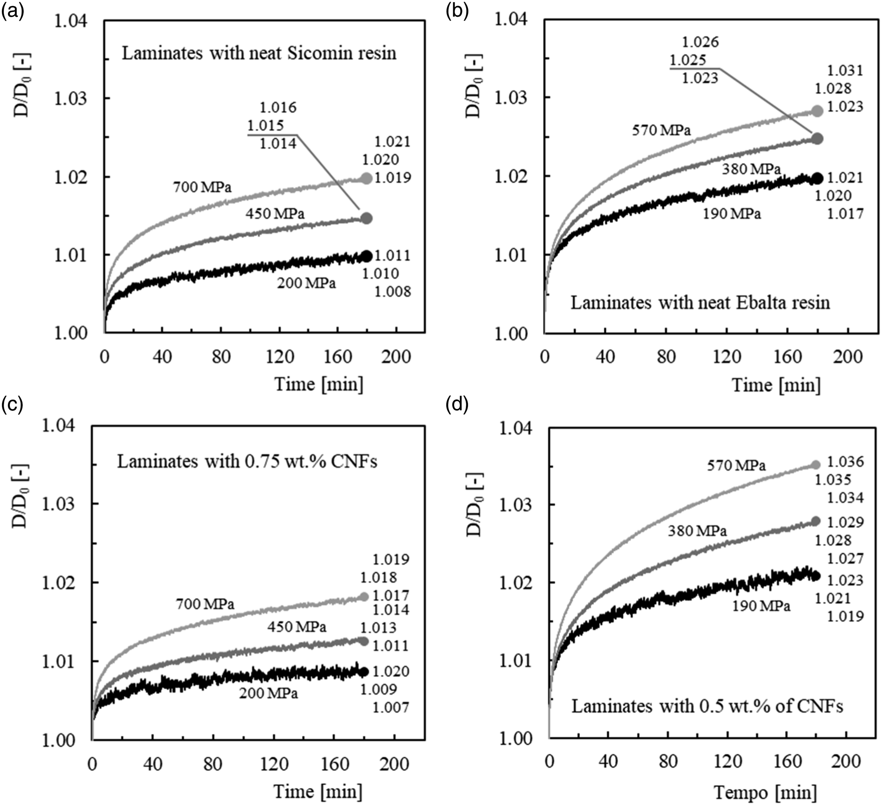
In terms of creep prediction, two models will be compared. Findley law (equation (2)) is widely used to describe the creep behaviour of composite materials20,43,45,46 and in some studies it is applied to short-term creep tests,46–48 which is given by
The other one is the KWW equation,
29
which is given by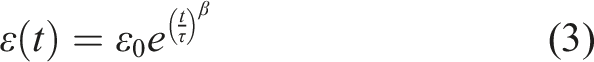
In this context, Figure 12 compares the experimental and theoretical curves obtained with the KWW and Findley models for laminates produced with Ebalta resin reinforced with 0.5 wt% CNFs. This evaluation is representative of all analyzed conditions, where the final bands represent the maximum and minimum values obtained in each analyzed condition. Tables 3 and 4 summarize all the constants of Findley’s law and the KWW model, respectively, while Tables 5 and 6 present the constants of the equations that fit the two models (Figure 12(b) and 12(c)). (a) Comparison between experimental and theoretical curves for laminates with Ebalta resin reinforced with 0.5 wt% CNFs and a bending stress of 190 MPa; (b) KWW parameters versus bending stress; (c) Findley parameters versus bending stress. Constants of Findlay’s law for creep. aValues used in the forecast. Constants of KWW model for creep. aValues used in the forecast. Constants of the equations that fit the Findley model. R2 = Squared correlation coefficient. Constants of the equations that fit the KWW model. R2 = Squared correlation coefficient.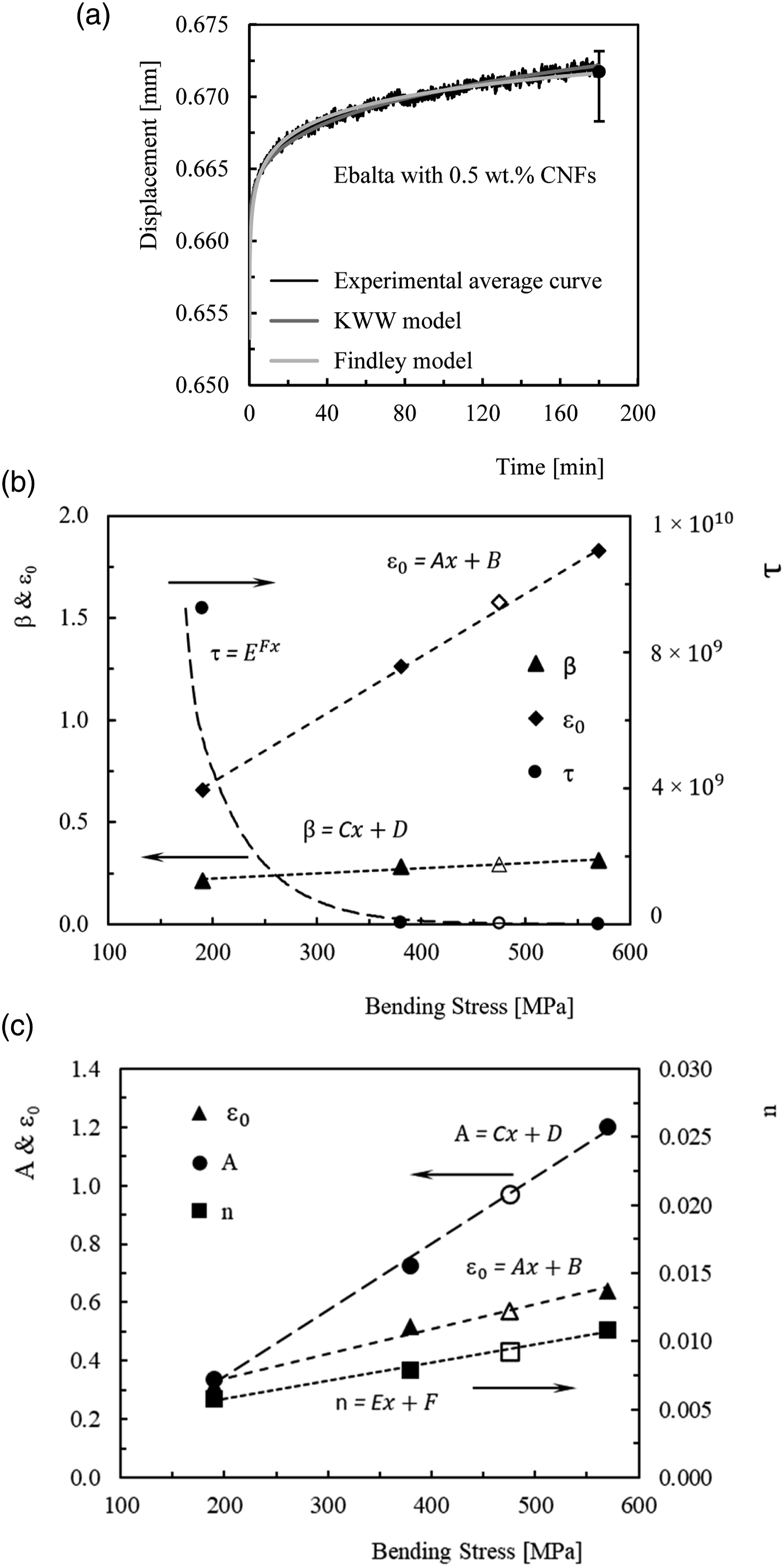
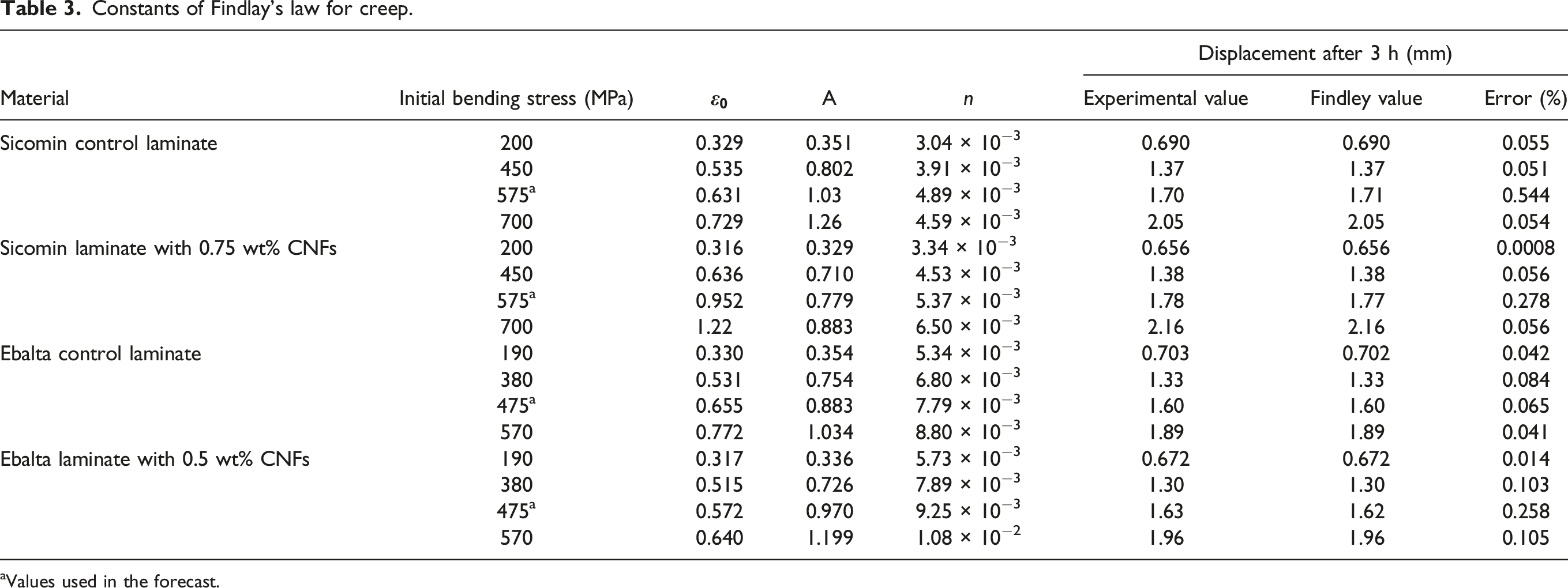
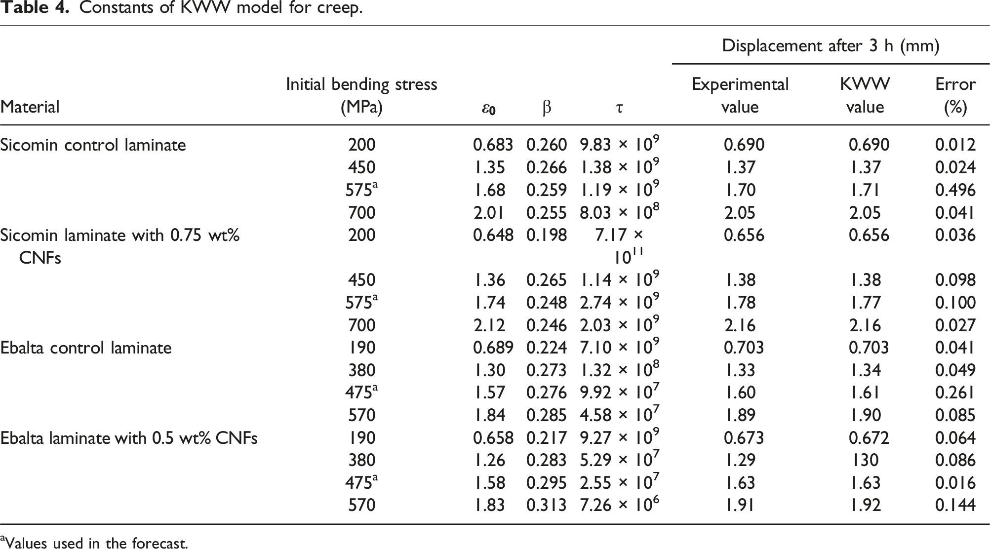
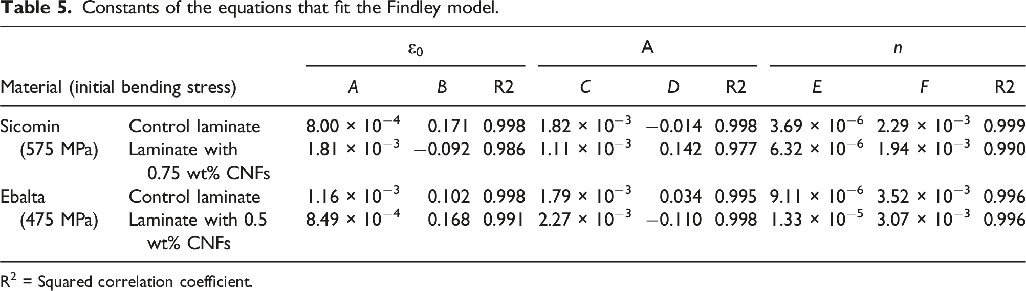
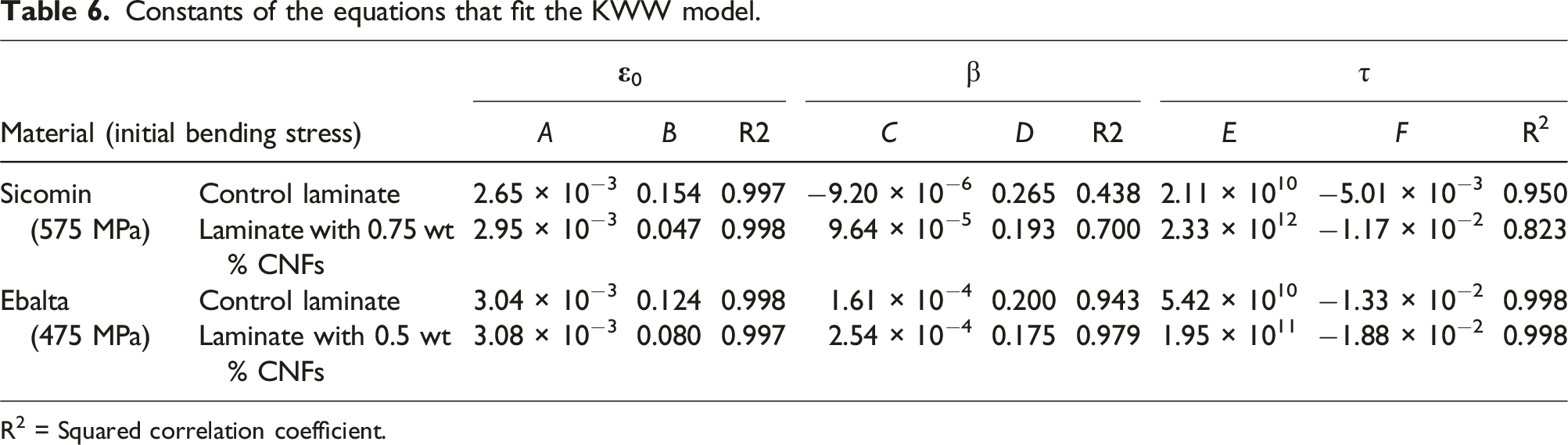
From Figure 12(a), it is possible to observe the good accuracy obtained with both models, in which the errors between the theoretical and experimental curves are 0.014% and 0.064% after 180 min of testing and for Findley’s law and the KWW model, respectively. However, this evidence can be generalized to all conditions and materials because, as shown in Tables 3 and 4, the maximum error obtained with these models is less than 0.6%. In terms of prediction, a methodology similar to that used for stress relaxation is utilized to predict the creep response for any bending stress. 29 In this context, Figures 12(b) and 12(c) illustrate this methodology for laminates produced with Ebalta resin reinforced with 0.5 wt% of CNFs, as well as the bending stress value of 475 MPa (corresponding to the white marks) that will be used for validation. Nevertheless, this procedure was applied to all materials and the values of the respective equations used to predict the creep displacement are shown in Tables 5 and 6
Considering the values shown in Figure 12(b) (
Finally, the ability of these models to predict the structural behaviour for longer periods of time was evaluated and the good accuracy obtained is shown in Figure 13 for a bending stress of 475 MPa and 100 h of testing (33.4 times longer than the time used in short-term tests). It is possible to observe that the error obtained by Findley’s law is around 0.2% and by the KWW model is about 0.4%. Furthermore, it is noticed that Findley's law leads to creep displacements slightly higher than the experimental values, while with the KWW model they are slightly lower. However, in both cases, the theoretical values are within the experimental scatter, revealing that this methodology can be used to estimate the effect of bending stress on the creep response for longer periods of time with good accuracy. However, similar to the results observed for stress relaxation, further studies for other materials and longer periods of time will be needed to confirm the robustness of the models. Comparison between experimental and theoretical curves for 100 h and bending stress of 475 MPa.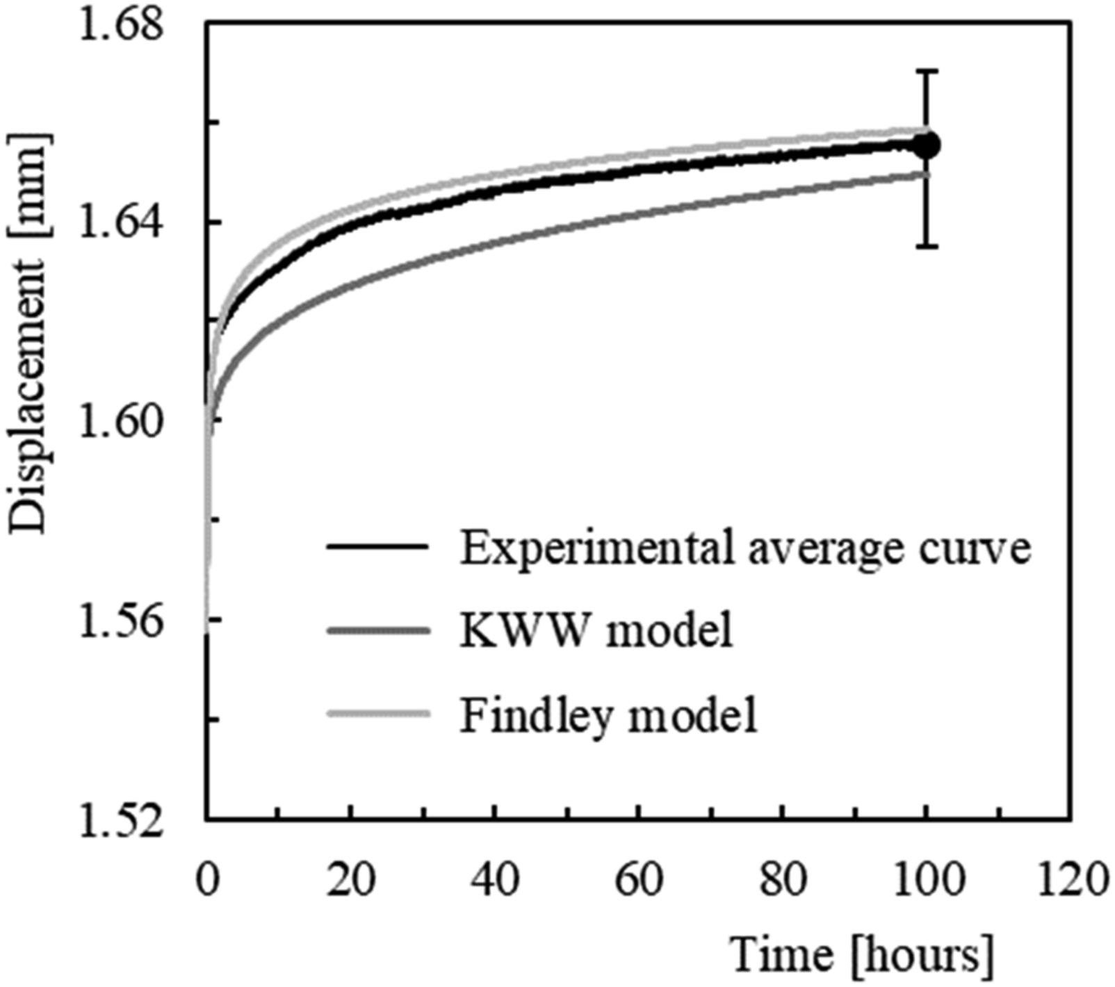
Conclusions
In the present work, the viscoelastic properties of CFRP composite laminates produced by hand lay-up technique, with two epoxies resins Sicomin and Ebalta, nano-enhanced by CNFs were studied. From the results of the different characterization tests, the main conclusions were drawn: - Static tests show a quasi-brittle behaviour and the bending stress was maximized when the epoxies resins Sicomin and Ebalta were filled with 0.75 wt% and 0.5 wt% of CNFs, respectively. These values are about 20.4% (from 752.2 MPa to 905.3 MPa) and 12.5% (from 756.2 MPa to 850.9 MPa) higher than those obtained with the control laminates. - Stress relaxation and creep tests show that, for both resins, a strong dependence of the viscoelastic behaviour with the applied stress level. However, identical results were obtained between the filled and the control laminates. The addition of CNFs does not have a deleterious effect on the relaxation behaviour of the laminates. This denotes that the dispersed nanoparticles bind to the matrix via interphases, bridging segments and junctions to support the load, but are not in sufficient quantity to promote immobility of the polymer chains. - The viscoelastic behaviour of CFRP composites nano-enhanced with CNFs was accurately predicted by the Kohlrausch-Williams-Watts (KWW) model and Findley power law, where a maximum error of 0.9% and 0.6% for stress relaxation and creep, respectively, was obtained.
Footnotes
Declaration of conflicting interests
The author(s) declared no potential conflicts of interest with respect to the research, authorship, and/or publication of this article.
Funding
The author(s) disclosed receipt of the following financial support for the research, authorship, and/or publication of this article: This work was supported by the FCT - Fundação para a Ciência e a Tecnologia, I.P./MCTES, through national funds (PIDDAC), within the scope of the Unit I&D C-MAST (Centre for Mechanical and Aerospace Science and Technology), Project UIDB/00151/2020. This research was also sponsored by national funds through FCT-Fundação para a Ciência e a Tecnologia, under the projects UIDB/00285/2020 and LA/P/0112/2020.
Data Availability Statement
The authors declare that the data supporting the findings of this study are available within the article.