
Abstract
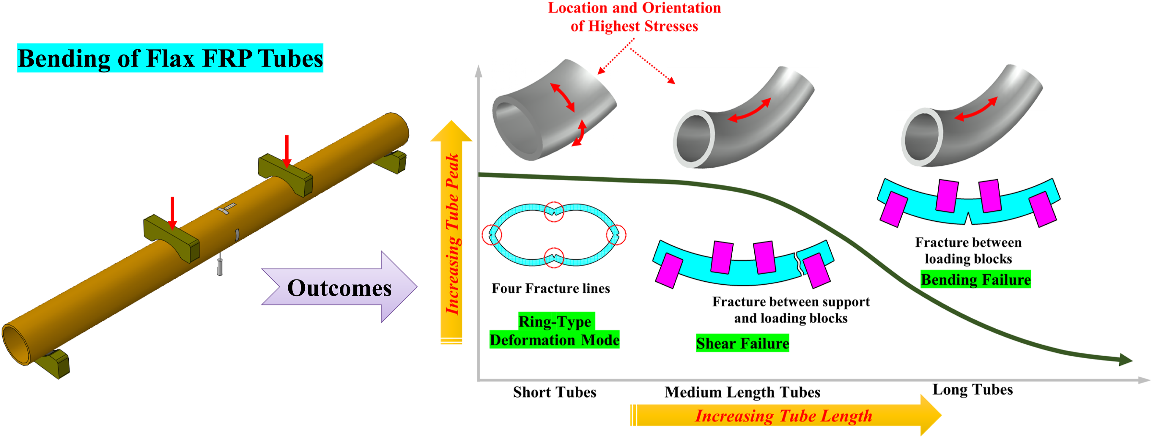
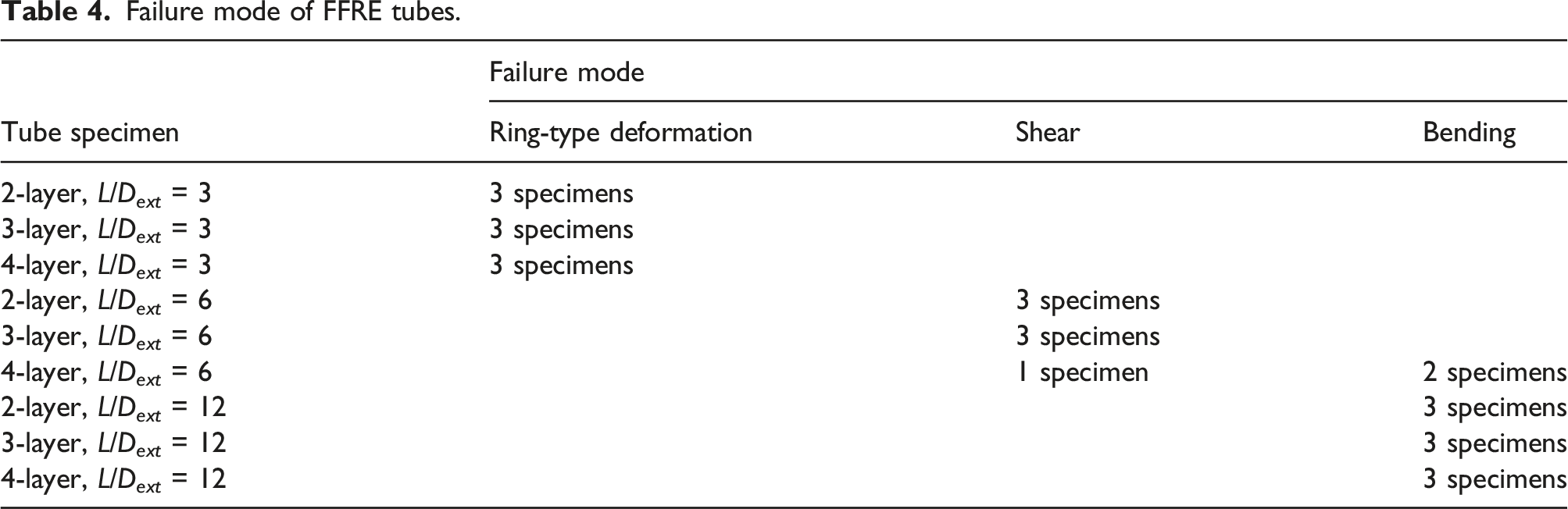
Flax fibre-reinforced polymer was used to manufacture 27 tubes. A parametric study was conducted to investigate the effect of length and wall thickness on the tubes’ bending capacity, strain behaviour, and failure mechanism which was investigated by conducting four-point loading experiments. The results indicated that with increasing the tube length, the failure mode of the tubes changed from ring-type deformation mode for short tubes to shear mode for medium-length and then to the bending mode for long tubes. While for short tubes, the largest strains developed in the hoop direction of the cross-section at mid-height, bottom, or top; for medium-length and long tubes, the largest strains occurred in the axial direction of the top or bottom cross-section.
Highlights
• Tubes’ failure mode changed from ring-type to shear, then bending with increasing length. • The largest strains changed from hoop to axial direction with increasing tube length. • Short tubes had comparable bending capacity to medium-length tubes.
Introduction
The use of plant fibres as a construction material has been increasing with the primary reason for this growth being the sustainability of plant fibres when compared to their counterpart synthetic fibres. 1 Substitution of synthetic fibres with plant fibres in various composite components has recently become a focus in composite research.2–8 Amongst 20 commonly used plant fibres, flax fibre had the best potential combination of high specific stiffness and strength and low cost to substitute glass fibre for structural applications, 9 and flax fibre-reinforced epoxy (FFRE) composites had comparable tensile strength to glass FRE (GFRE) composite. 10 Additionally, flax fibre is readily available, has a short growing cycle, and has minimal carbon foot-print when compared to counterpart synthetic and natural fibres.11,12
There is much literature regarding the mechanical and structural performance characteristics of various configurations of structural components manufactured or retrofitted with FFRE composites. Akin and Rashidi 13 showed that the confinement of concrete columns with FFRE caused a substantial gain in the strength and ultimate strain capacity of the columns. Huang et al. 14 reported that FFRE was an effective material for retrofitting damaged concrete beams. Bai et al. 15 declared that FFRE confinement improved the dynamic response of concrete members when subjected to impact loading. Codispoti et al. 16 showed that among flax, hemp, jute, sisal, and coir fibre FRE composites, FFRE was the most suitable plant fibre for retrofitting masonry structures. In the earlier studies by the authors of the current paper, FFRE pipes were shown to have great potential as a viable option to replace the application of conventional pipes.3,6,11,12,17–20
Tubes are extensively employed in a wide array of applications in various structural types in the construction, 21 pipeline,17,22 automotive, 23 aircraft industrial sectors, 24 and bending actions are the primary loading type for various tubular components in the course of installation and operation. For example, tubular members, when designed as elevated above-ground pipes, are subjected to bending actions due to the weight of the pipe material and the contained fluid and foundation subsidence.17,25 For buried pipes, land sliding and liquefaction and seismic loads can cause bending action to rise withing the pipe length. 26
The study is conducted as part of a thorough investigation of the structural and mechanical performance characteristics of FFRE tubes and is novel in that the effect of tube length and thickness on the bending response characteristics of FFRE tubes is investigated. The outcomes will be used in designing tubes that proved to have great potential to replace the use of counterpart tube members manufactured from non-sustainable materials. In the reported study, 27 FFRE tubes with varying numbers of fabric layers and varying length-to-external diameter ratios (L/D ext ) were manufactured and tested when subjected to four-point loading. The objective of this study is to carry out a parametric analysis to investigate the effect of the number of fabric layers and L/D ext ratio on the bending capacity, hoop and longitudinal strains, and failure mode of the FFRE tubes are investigated.
Experimental procedures
Material process
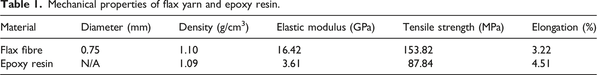
Mechanical properties of flax yarn and epoxy resin.
For tube manufacture, first, the external surface of a PVC tube (as a mandrel) with an external diameter of 60 mm was rubbed with formwork oil, then four polyethylene plastic stripes were aligned on the PVC tube’s external surface. A polyethylene plastic sheet was firmly wrapped and taped around the PVC tube. Flax fabric was completely saturated with resin and wrapped tightly around the PVC tube such that the wefts aligned the tube axial axis and the warps aligned transverse to the tube axial axis. FFRE tubes were then cured for 48 h and removed from the PVC tubes afterwards. FFRE tubes were then ready for testing. The details of the tube manufacturing process are thoroughly described in the earlier study by the authors. 11
Test specimens and instrumentation
Geometric properties of FFRE tubes.
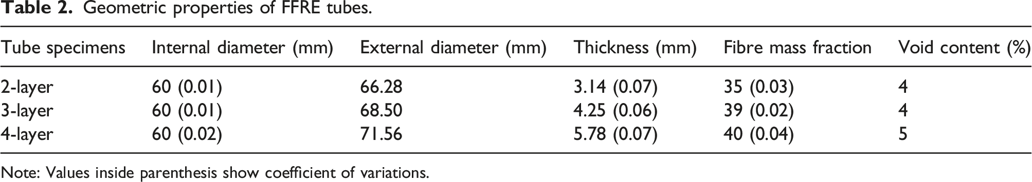
Note: Values inside parenthesis show coefficient of variations.
Four-point loading tests on the tube specimens were conducted using a 100 kN Instron machine, with the loading rate setting to 2 mm/min. The schematic view of the test set-up is shown in Figure 1. The tubes were placed on two support blocks with a sector length equal to 120° at 25 mm overlay from each tube end, and the loading was applied to the tubes using two loading blocks with similar sector length to support blocks at the 1/3rd and the 2/3rd of the tube span. Six strain gauges (product of Tokyo Measuring Instrument Lab, type BFLAB) were installed at the tube mid-span cross-section, four of which were aligned along the tube hoop direction at the mid-height of the cross-section and the tube top and the tube bottom, and two strain gauges were aligned along the tube axial direction at the tube top and the tube bottom. Vertical displacement of the tube specimens at the bottom of the tube mid-span was measured using a linear variable displacement transducer (LVDT, RDP, series LDC). Schematic view of test set-up for four-point loading on tubes.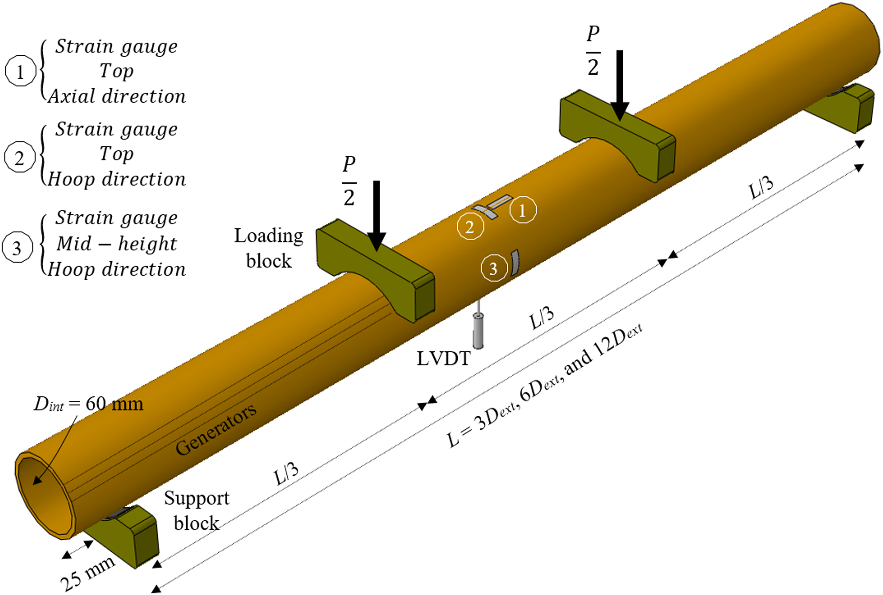
Mechanical properties of tube material
Mechanical properties of FFRE composite with varying numbers of fabric layer.
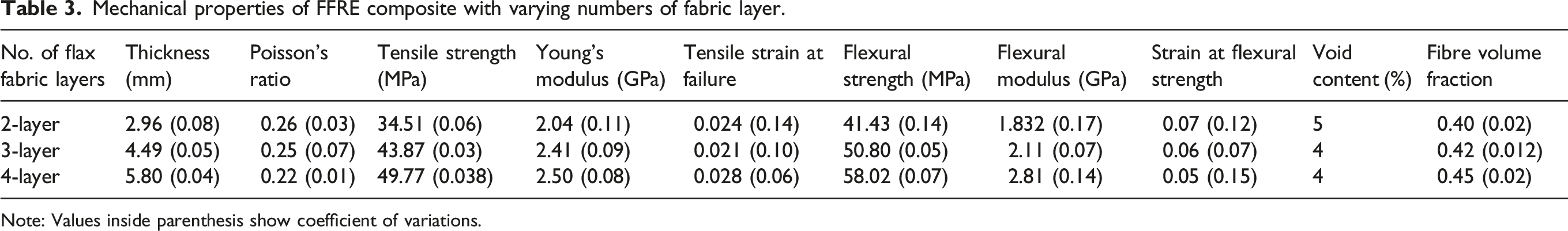
Note: Values inside parenthesis show coefficient of variations.
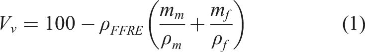
The averaged values of void content for the tubes and the coupon samples are given in Tables 2 and 3, respectively.
Results and discussion
Failure mechanism
Tubes with L/D
ext
= 3 were ovalised when subjected to four-point loading, and the cross-sectional deformation was in the same direction as the cross-sectional deformation beneath the loading blocks. Minimal bending of the generators (imaginary lines at an equal distance from the tube axial axis that form the tube geometry,
21
see Figure 1) occurred up to the tube fracture load, and the primary deformation was hoop bending around the generators. Four horizontal fracture lines developed at the mid-height, the top, and the bottom of the cross-section (Figure 2(a) and (b)), with this failure mode resembling the failure of tubes when laterally compressed between rigid plates at the top and bottom, which is recognised as the ring-type deformation mode.3,34 Failure mode of FFRE tubes with various L/D
ext
ratios. (a) 4-layer tube with L/D
ext
= 3 after test, (b) Final cross-section of 4-layer tube with L/D
ext
= 3, (c) Beam-like bending deformation mode of tube with L/D
ext
= 12, (d) Fracture of 3-layer tube with L/D
ext
= 12, (e) 3-layer tube with L/D
ext
= 6 and (f) 4-layer tube with L/D
ext
= 6.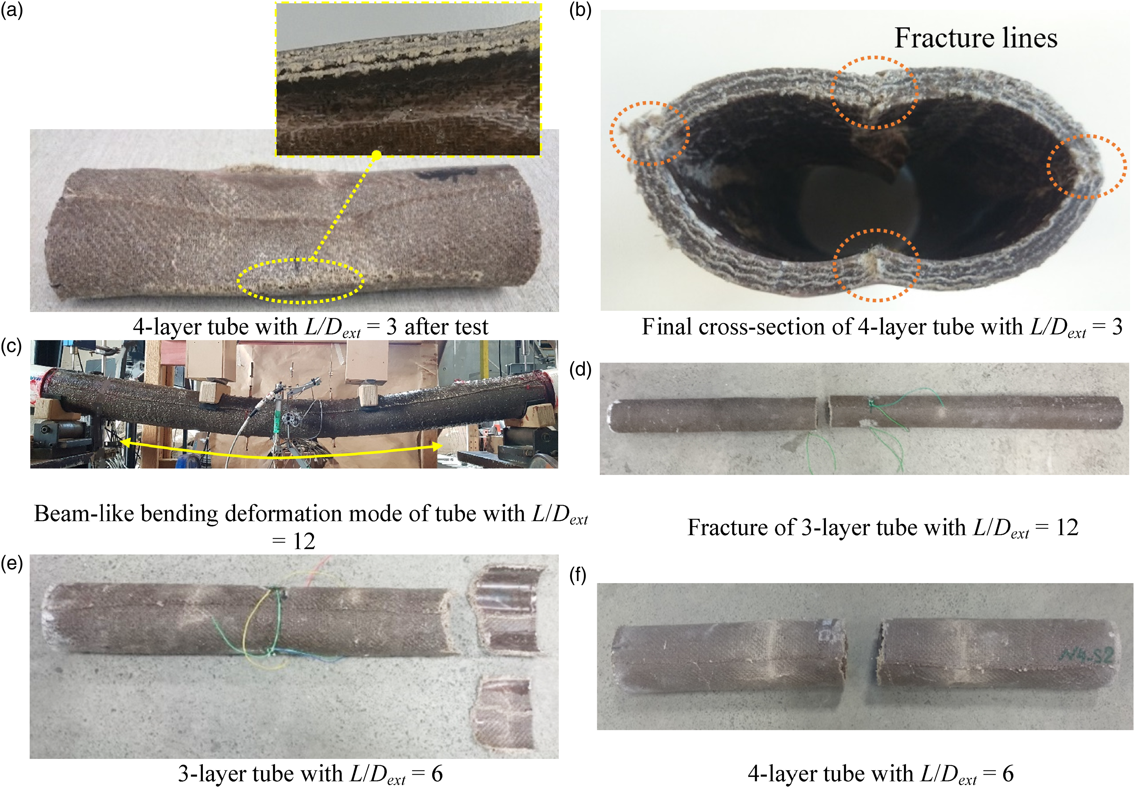
Failure mode of FFRE tubes.
Load-displacement relationships
In Figure 3, load-displacement relationships of three repeated tests of two-layer tubes with L/D
ext
of 3, three-layer tubes with L/D
ext
ratios of 6, and three-layer tubes with L/D
ext
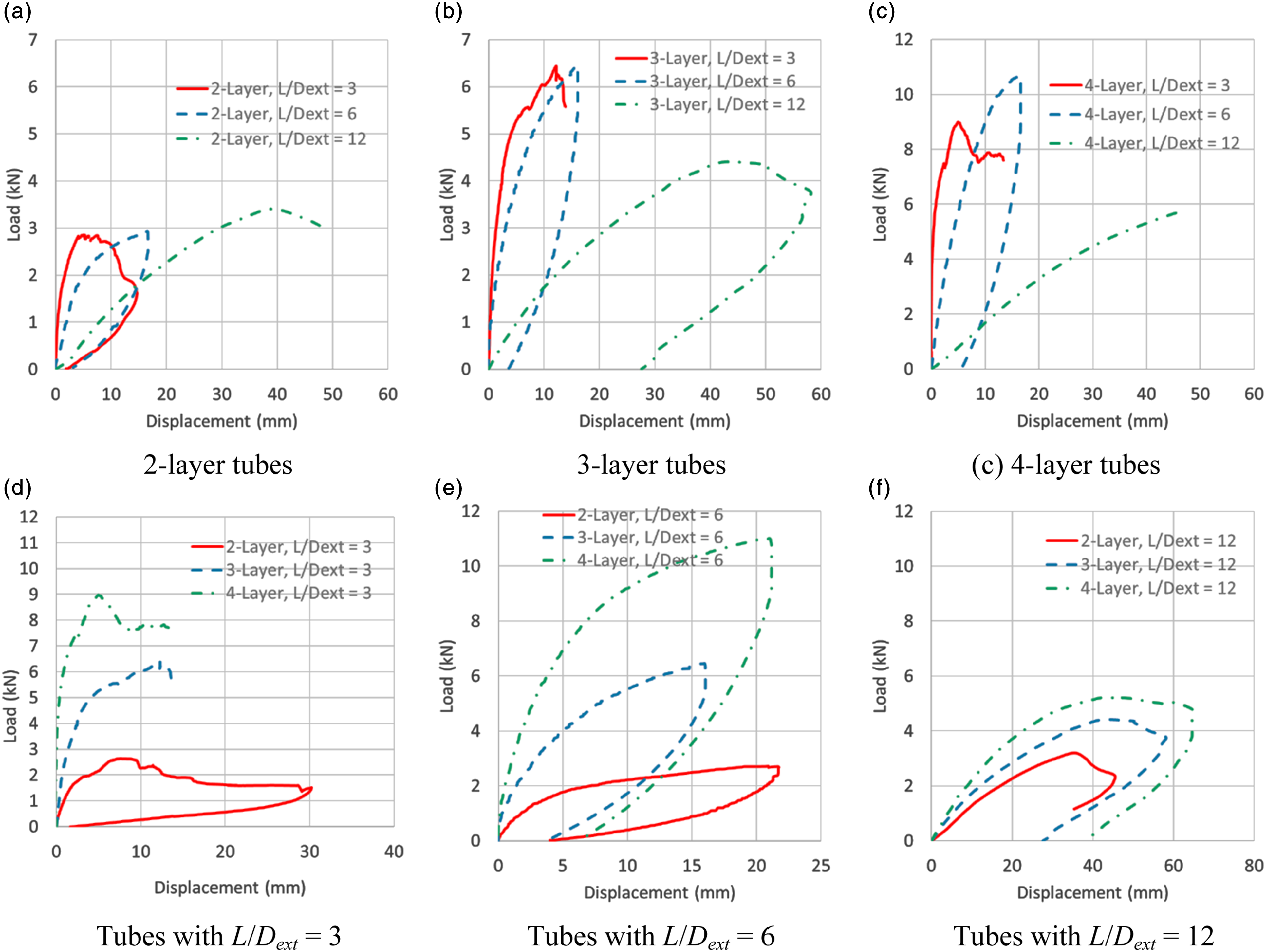
ratios of 12, as examples of nine groups of tubes, are presented. Remarkable similarities in the load-displacement response of the three repeated tests were established, considering tube manufacturing technique (manual fabric winding) and constituent materials (plant fibre). In Figure 4(a)–(c), the load-displacement relationships of tubes with the same number of fabric layers but various L/D
ext
ratios, and in Figure 4(d)–(f), the load-displacement relationships for tubes with the same L/D
ext
ratio but various numbers of fabric layers are presented. The results indicated that with increasing the L/D
ext
ratio or decreasing the number of fabric layers, the stiffness of the tubes decreased due to reducing the moment of inertia of the tube cross-section. Load-displacement relationships of three repeated testes of FFRE tubes with similar L/D
ext
ratios and number of fabric layers. (a) 2-layer tubes with L/D
ext
= 3, (b) 3-layer tubes with L/D
ext
= 6 and (c) 3-layer tubes with L/D
ext
= 12. Load versus vertical displacement relationships of FFRE tubes. (a) 2-layer tubes, (b) 3-lyaer tubes, (c) 4-layer tubes, (d) Tubes with L/D
ext
= 3, (e) Tubes with L/D
ext
= 6 and (f) Tubes with L/D
ext
= 12.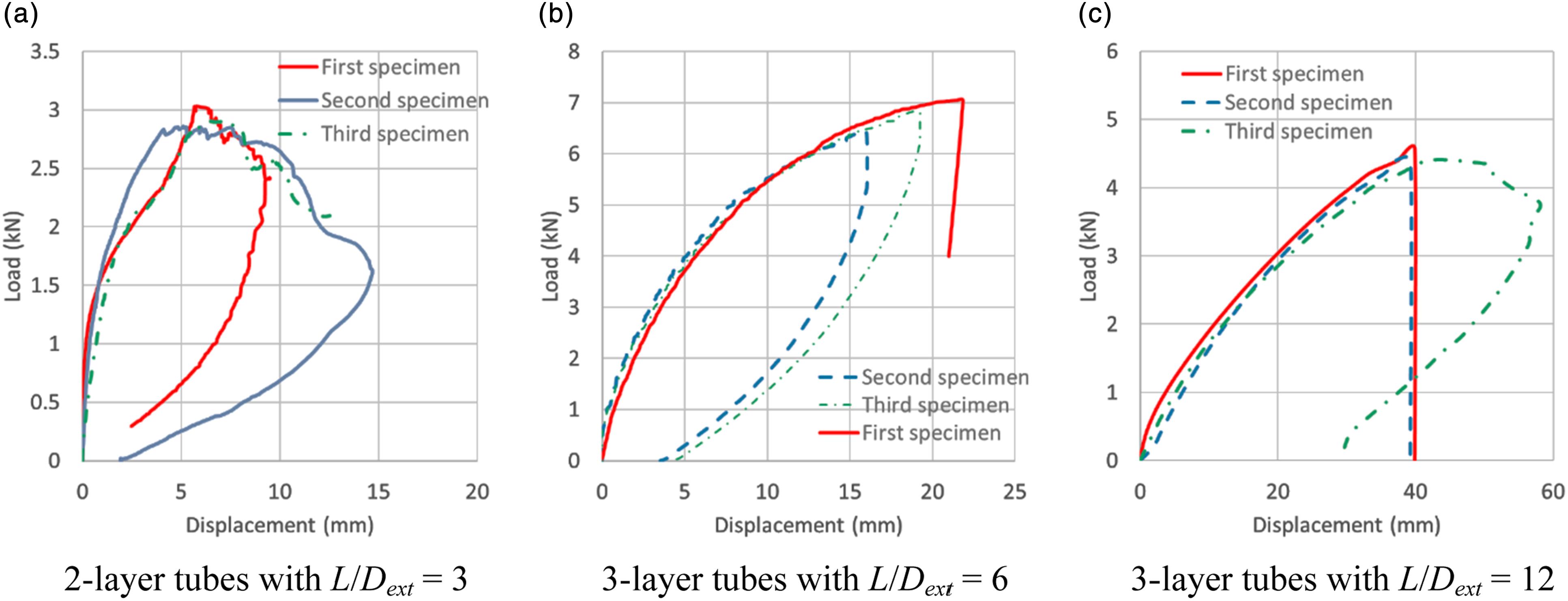
The average values of the peak load for tubes with the same number of fabric layers but various L/D
ext
ratios are shown in Figure 5(a), and the average values of the peak load for tubes with the same L/Dext ratios but various numbers of fabric layers are shown in Figure 5(b). The results revealed that tubes with L/Dext = 3 and 6 had comparable but larger values of peak load when compared to tubes with L/D
ext
= 12. The results also showed that peak loads increased by increasing the number of fabric layers. Average peak load of tubes with different L/D
ext
ratios and numbers of fabric layers. (a) Tubes with the same number of fabric layers and (b) Tubes with the same L/D
ext
ratio. Note: Values inside parentheses indicate coefficient of variations.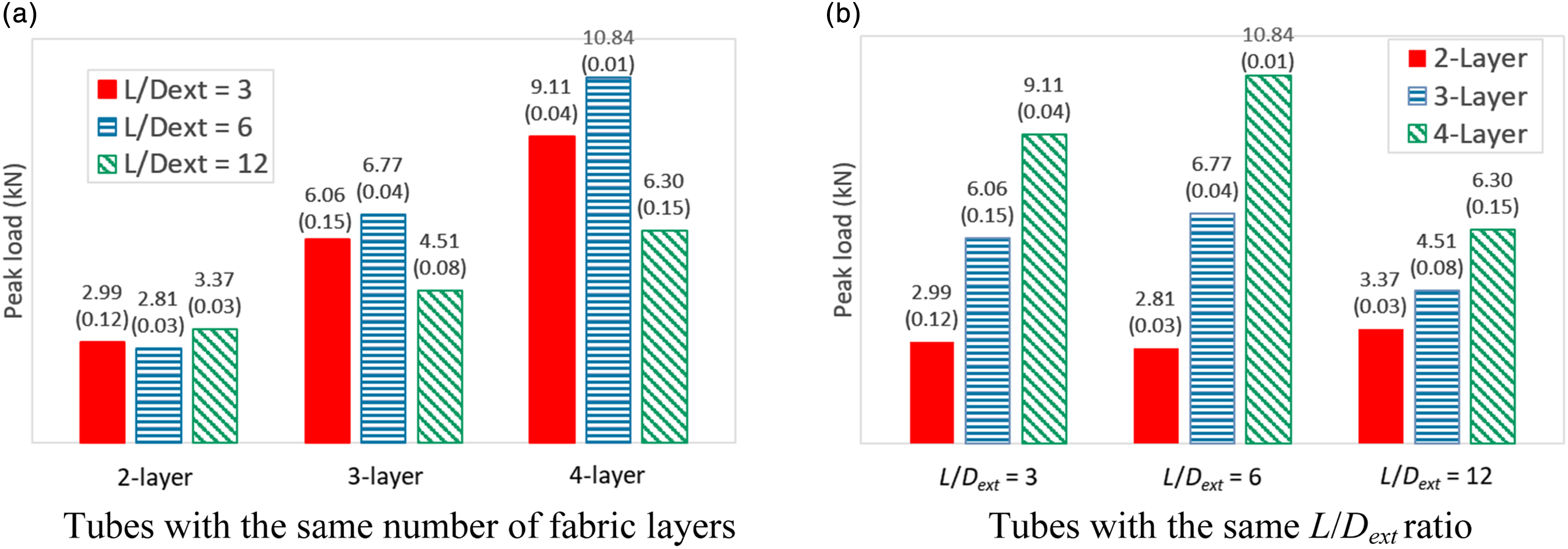
Strain response
Load-strain relationships of three tubes for six strain gauges at various locations and orientations of the tube mid-length are shown in Figure 6. The absolute values of longitudinal and hoop strains at the top and the mid-height of the cross-section were similar to the counterpart strains at the bottom and the opposite side of the mid-height of the cross-section, respectively (Figure 6). Therefore, in Figure 7, longitudinal and hoop strains at the bottom and hoop strains at one side of the mid-height of the cross-section are only presented. In Figure 7, load-strain relationships of the tubes with various L/D
ext
ratios and different numbers of fabric layers at different locations in the tube cross-section are presented. Longitudinal strains developed at the tube bottom surface were tensile due to the beam-like bending deformation mode, and hoop strains recorded at the mid-height of the cross-section were tensile due to the tube cross-sectional ovalisation. For the case of tubes with L/D
ext
= 3, hoop strains at the bottom surface of the cross-section were compressive due to the inward deformation of the cross-section at the bottom (Figure 2(b)), whilst for tubes with L/D
ext
= 6 and 12, the hoop strains at the bottom surface of the cross-section were compressive because of Poisson’s ratio effect. Comparison of axial and hoop strains at various locations of tube mid-length cross-section. (a) 2-layer tube with L/D
ext
= 3, first specimen, (b) 4-layer tube with L/D
ext
= 6, second specimen and (c) 3-layer tube with L/D
ext
= 12, first specimen. Load versus strain relationships at various locations of FFRE tubes. (a) 2-layer tube with L/D
ext
= 3, third specimen, (b) 4-layer tube with L/D
ext
= 6, first specimen and (c) 3-layer tube with L/D
ext
= 12, third specimen.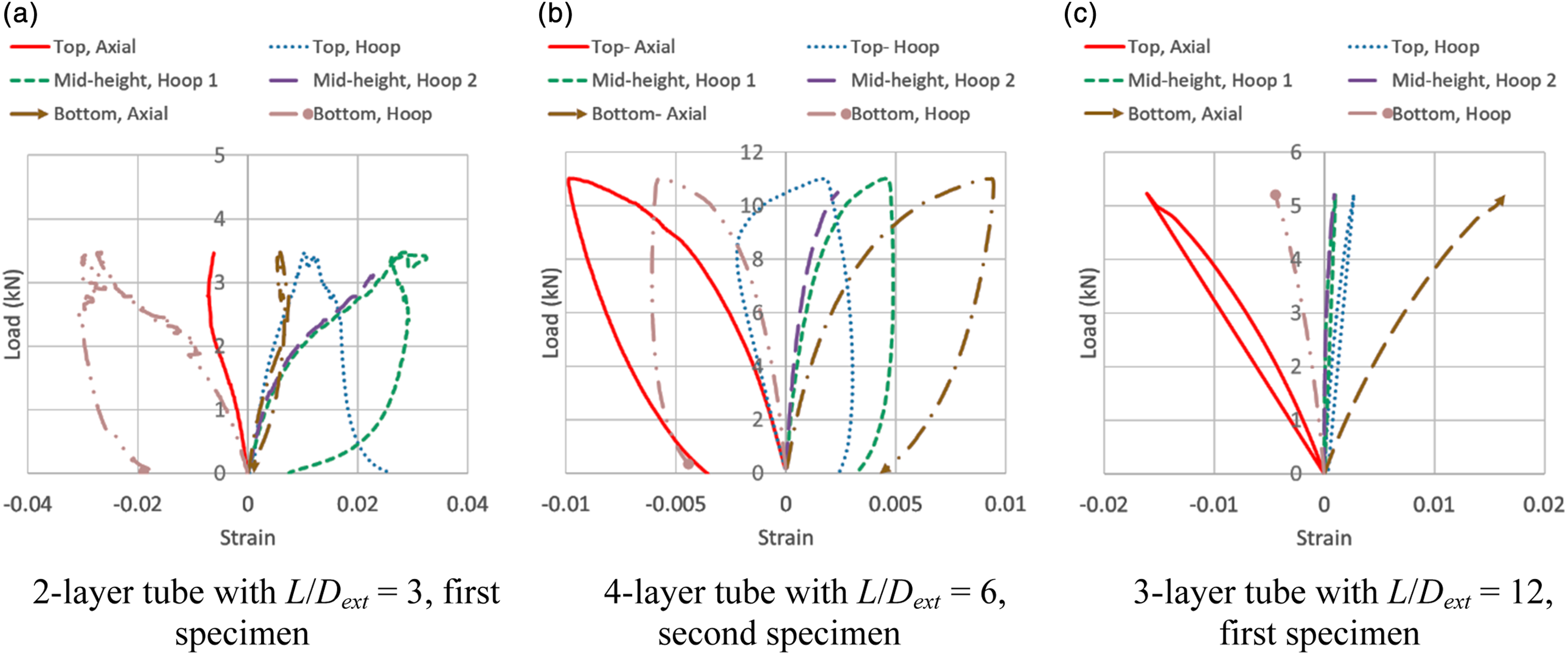
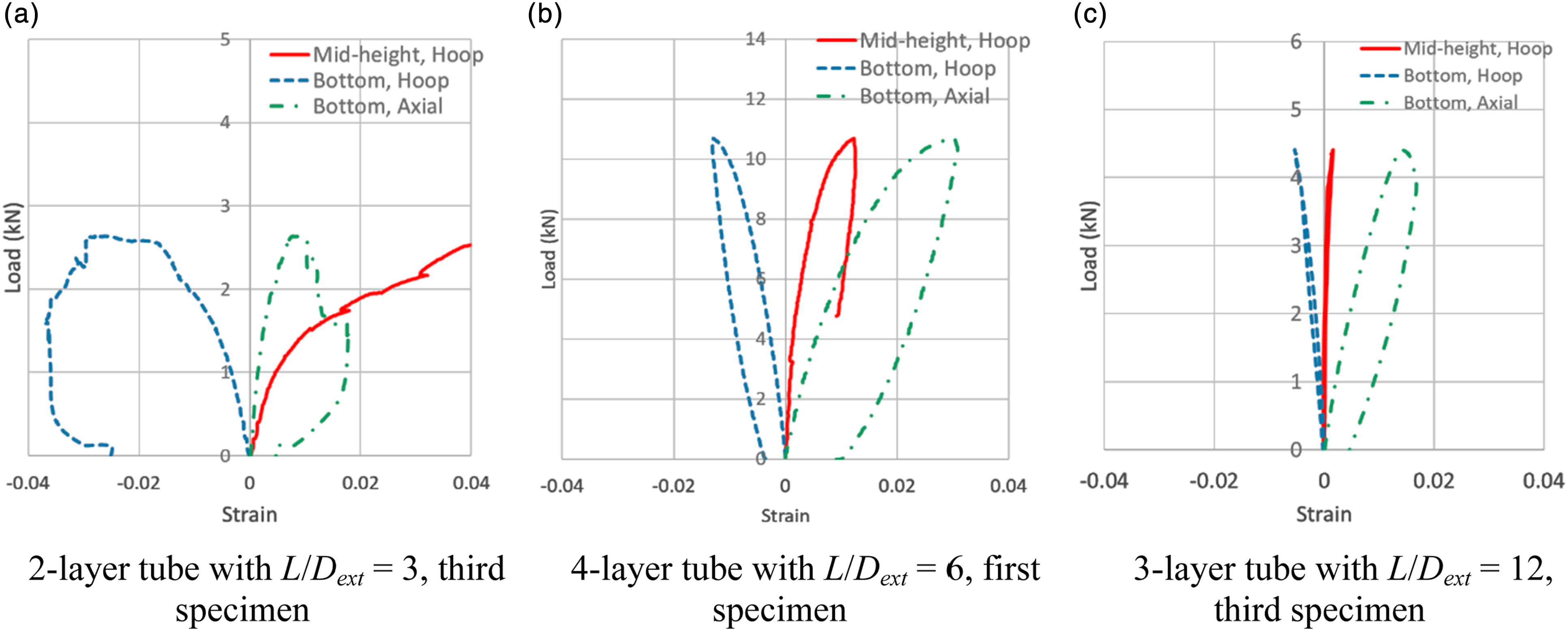
In the case of tubes with L/Dext = 3 and for a given load, the largest absolute strains occurred in the hoop direction of either the cross-sectional mid-height or the bottom surface of the cross-section, resulting from gross ring-type deformation mode (Figure 2(a) and (b)). In the case of tubes with L/D ext = 6 and 12, longitudinal strains at the tube bottom surface were the largest due to excessive beam-like bending deformation mode (Figure 2(e)). The results indicated that by increasing the L/Dext ratio, the location of the largest strains was changed from the hoop direction at the mid-height, the bottom or the top of the cross-section to the longitudinal strains at the bottom or the top of the tubes.
In Figure 8(a)–(c), load versus strain relationships for tubes with the same number of fabric layers but various L/Dext ratios, and in Figure 8(d)–(f), load versus strain relationships for tubes with the same L/D
ext
ratio but varying numbers of fabric layers at the location of the largest strains are depicted. The results showed that for a given number of fabric layers and a given load, the largest strains either developed in tubes with L/D
ext
= 3 or in tubes with L/D
ext
= 12, and for a given L/D
ext
ratio and a given load, strains decreased with increasing the number of fabric layers due to increasing the tube stiffness. Load versus strain relationships of FFRE tubes at location of largest strains. (a) 2-layer tubes, (b) 3-layer tubes, (c) 4-layer tubes, (d) Tubes with L/D
ext
= 3, (e) Tubes with L/D
ext
= 6 and (f) Tubes with L/D
ext
= 12.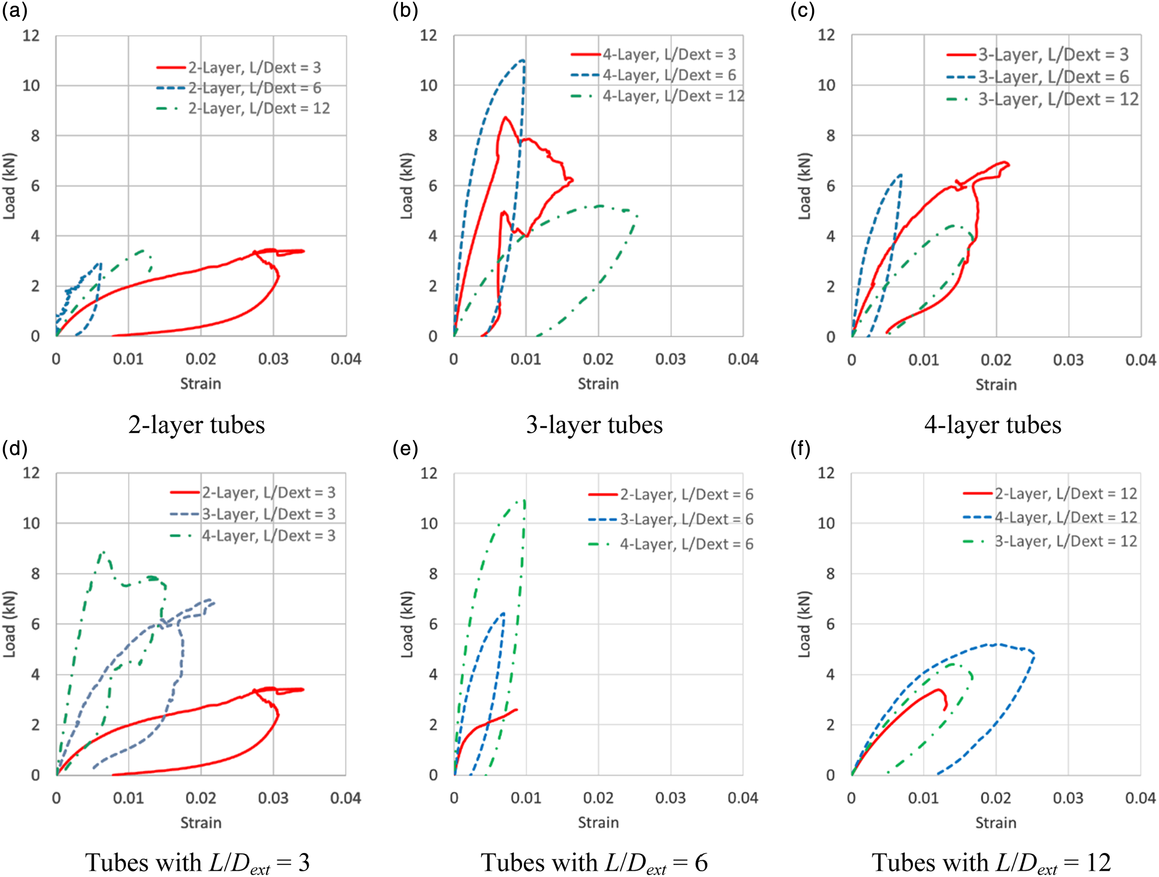
Conclusions
The effect of the length-to-diameter ratio (L/D = 3, 6, and 12) and the number of fabric layers (2, 3, and 4) on the response of flax fibre-reinforced epoxy polymer (FFRE) tubes, when subjected to four-point loading, was investigated. For a given number of fabric layers, the failure mode of tubes depended on the L/D ratio. The failure mode of tubes with L/D = 3 was akin to the failure of tubes when subjected to lateral compression via parallel rigid plates at the top and the bottom and consisted of the development of four fracture lines at the top, the bottom, and the mid-height of the tube cross-section. While tubes with L/D = 6 fractured either due to excessive shear or bending stresses, tubes with L/D = 12 fractured in the tube mid-span area due to the excessive bending stresses. Although the stiffness of tubes decreased with increasing the L/D ratio, tubes with L/D = 6 and 12 had comparable but larger values of peak load when compared to tubes with L/D = 12. The location of the largest strains developed in the cross-section depended on the L/D ratio. For tubes with L/D = 3, the largest strains were in the hoop direction of the mid-height, the bottom, or the top of the cross-section. For tubes with L/D = 6 and 12, the largest strains developed in the axial direction and at the bottom or the top of the cross-section.
The concrete message of the current research is that whilst for the bending design of short tubes (L/D ≤ 3), hoop stresses dominated the design criteria for the bending design of long tubes (L/D ≥ 12); longitudinal stresses dominated the design criteria. Both longitudinal and circumferential stresses dominated the design criteria for the bending design of medium-length tubes (3 < L/D < 12).
Footnotes
Declaration of conflicting interests
The author(s) declared no potential conflicts of interest with respect to the research, authorship, and/or publication of this article.
Funding
The author(s) received no financial support for the research, authorship, and/or publication of this article.