
Abstract
In the study, parts are fused deposition modeling–printed using polylactic acid filaments filled with copper, brass, bronze, tungsten, and carbon fiber. Wear and three-point bending tests are applied to FDM-printed specimens and it is yielded that on-edge oriented specimens had higher flexural strength while flat orientation contributed to wear resistance. Wear tracks are examined, and mostly abrasive wear is detected in the dry sliding condition while adhesive, fatigue and abrasive wear is observed in the wet sliding condition. Brass-filled polylactic acid specimens showed highest flexural strength and flexural modulus with 46.73 MPa and 1.53 GPa, respectively. Besides, the most wear resistant filler is determined as tungsten for dry and wet sliding conditions.
Introduction
In the material extrusion, fused deposition modeling (FDM) or fused filament fabrication (FFF) is a low-cost and easy-to-manufacture technique in terms of 3D printer equipment, filament, and software for printing of thermoplastic polymer parts. 1 In the manufacture of thermoplastic polymer parts, a large number of polymers are utilized in the form of filament, such as acrylonitrile-butadiene-styrene (ABS), 2 polylactic acid (PLA), 3 polycarbonate (PC), 4 polyethylene terephthalate glycol (PETG), 5 polypropylene (PP), 6 and polyether ether ketone (PEEK). 7 It is stated that 8 ABS and PLA are the most studied polymers in FDM/FFF additive manufacturing system. In the trend of replacing petrochemical-based polymers, utilization of PLA is progressively increasing 9 in the areas such as biomedical, 10 membranes, 11 fibers and food packaging. 12
PLA is a synthetic, versatile, biodegradable, aliphatic polyester, which is mostly derived by polymerizing of agricultural lactide and lactic acid.13,14 The most utilized synthesis routes of PLA are direct polycondensation of lactic acid and ring-opening polymerization of lactide. 15 Its mechanical properties such as density, ultimate tensile strength, elastic modulus, and stiffness are higher compared to most of the polymers, but it suffers due to low ductility and toughness. Some plasticizer and additives are blended with PLA to improve its low mechanical properties.16,17 However, additional fillers are needed to increase its performance and functionality to enhance its application area. 18
Mechanical properties of FDM-printed parts depend on numerous printing parameters such as air gap, build orientation, extrusion temperature, infill density, infill pattern, layer thickness, print speed, raster width, and raster orientation. 19 It is reported that the most critical FDM process parameters are build orientation, layer thickness, infill pattern, infill density, and nozzle diameter 20 in FDM-printed parts. Altan et al. 21 investigated the effect of layer thickness, nozzle temperature and printing speed on surface roughness and tensile strength of FDM-printed PLA parts. The most dominant printing parameters are determined as layer thickness and printing speed. Moreover, lower values of layer thickness unveiled increased tensile behavior and surface roughness. In addition, nozzle temperature and using of a cooling fan affected the properties insignificantly. Rajpurohit and Dave 22 studied the effect of layer thickness, raster angle, and raster width on tensile strength of FDM-printed PLA specimens. Compatible with Altan et al., 21 lower layer thickness revealed higher tensile strength due to higher bonding area between layers. Also, raster width proportionally increased the tensile strength up to the formation of voids in the interlayers and lower raster angle values provided higher tensile strength. Singh et al. 3 conducted a detailed investigation on the effect of infill density (40%, 60%, and 80%) and raster pattern (grid, triangle, and concentric) for varied build orientations (horizontal, on-edge, and vertical) in terms of tensile properties of FDM-printed PLA parts. The highest tensile strength is reached for concentric raster pattern, 80% infill density and on-edge orientation. In terms of build orientation, horizontal and on-edge orientations followed parallel loading criteria which are compatible with the parallel deposition. That is why horizontal and on-edge orientations provided higher tensile strength of FDM-printed PLA parts. Eryildiz 23 experimentally investigated build orientation effect on tensile properties of FDM-printed PLA parts and it is revealed that highest and lowest tensile strength are obtained with flat and upright orientations, respectively. The intralayer and interlayer phenomena enabled the difference in the tensile strength of PLA parts.
Modifying printing parameters of pure PLA parts in FDM process can enhance its mechanical properties up to a certain point, that is why reinforcing PLA parts with different filler materials are under scope of the industry. Thereby, various fillers are blended with PLA to provide higher performance in terms of durability, toughness, tribological, thermal, and electrical properties. Graphite, 24 copper, 25 aluminum, 26 CF, 27 bio-ceramics, 28 and carbon nanotube 29 are the most studied reinforcements in the PLA filaments. Kottasamy et al. 30 studied copper reinforcement (25 and 80 wt.%) in the FDM-printed PLA specimens in terms of tensile, compression and flexural strengths and printing parameters are defined as 0.4 mm nozzle diameter, 210°C extruder temperature, 30 mm·s−1 printing speed, and 60°C print bed temperature. It is reported that 25 wt.% Cu addition showed superior mechanical resistance compared to 80 wt.% reinforcement in terms of tensile, compressive, and flexural strengths. Venkata Pavan et al. 31 blended 20–30 μm copper particulates with PLA powder in ratios of 4, 8, 12, 16, and 20 wt.% and investigated the effect of process parameters on impact and shear behavior in terms of following parameters: 190–230°C extruder temperature, 50–70°C bed temperature with 100% infill percentage for 12 wt.% Cu-filled PLA parts. It is mentioned that adding filler material more than 20% is hard to extrude composite filament continuously. Increase in filler ratio lowered ductility and enhanced hardness and filament density. Liu et al. 32 studied the effect of build orientation and raster angle on mechanical properties of composite PLA parts. Wood and chopped CF addition to pure PLA lowered its properties and on-edge orientation of composite PLA provided highest strength while the upright orientation gave the lowest strength for the following printing parameters: 200°C nozzle temperature, 80 mm·min−1 printing speed, 0.4 mm nozzle diameter, and 100% infill density. Maqsood and Rimasauskas 33 examined the tensile and flexural properties of PLA parts reinforced with short, continuous, and short/continuous CF. Continuous CF-filled PLA gave the highest tensile and flexural strength, and increasing CF ratio provided higher elastic modulus, but lowered ductility. Two different FDM printers are used, and separate printing parameters are selected: 1.5–and 0.4 mm nozzle diameter, 3 and 25 mm·s−1 printing speed, 210°C and 250°C extruder temperature, 90°C and 75°C bed temperature and 100% infill density. Cao et al. 34 investigated tensile properties of FDM-printed CF-filled PLA parts. 5 mm/s printing speed, 210°C extruder temperature, 60°C bed temperature, 0.4 mm nozzle diameter and 100% infill density are selected as printing parameters. Crystallization degree of CF-filled PLA is higher than the neat PLA which attributed to the heterogenous nucleation effect of variously oriented fiber in the matrix. In terms of tensile properties, bad bonding, and varied orientations of fibers lead to lower tensile strength of CF-filled PLA compared to the neat PLA. Selvamani 35 investigated the tensile properties of FDM-printed PLA parts filled with 15 and 70 wt.% brass reinforcements for varied infill patterns with 50% infill density for the following printing parameters: 0.4 mm nozzle diameter, 190°C nozzle temperature, 60°C bed temperature, and 30 mm·s−1 printing speed. Highest tensile strength, elastic modulus and yield strength are achieved with 15 wt.% brass reinforcement for concentric infill pattern due to stronger bonding strength. Hanon et al. 36 examined dry sliding wear properties and tensile strength of FDM-printed bronze-filled PLA parts for different build orientations. On-edge printed parts gave the highest tensile strength and vertical oriented parts provided lowest wear depths. For bronze-filled PLA printing, following parameters are used: 0.4 mm nozzle diameter, 195°C extruder temperature, 60°C bed temperature. Moradi et al. 37 experimentally investigated bronze-filled PLA parts in terms of process parameters on mechanical properties. Following printing parameters are utilized to print the specimens: 0.45 mm nozzle diameter, 60 mm·s−1, and nozzle temperature between 190 and 235°C. It is reported that increase in layer thickness significantly improved tensile resistance, but maximum failure load is affected most by layer thickness, infill percentage, and extruder temperature. Yoon et al. 38 studied X-ray shields made of tungsten-filled PLA manufactured by FDM. The filament consisted of 90% tungsten and X-ray shields are printed in rectangular shape with varied thicknesses. The following process parameters are utilized in the printing: 0.4- and 0.8- mm nozzle diameter, 0.1–0.4 mm layer height, 213°C extruder temperature, 65°C bed temperature, 100% infill density, and 50 mm·s−1 printing speed. It is shown that 1 mm thick shield sheet provided more than 90% shielding rate compared to commercial lead-based shields which can be a promising substitutive instead of lead shields. Maguluri et al. 39 investigated effect of printing parameters on mechanical properties of neat PLA parts by adjusting nozzle temperature 190–220°C, infill density 50–100%, printing speed 20–40 mm·s−1. It is determined that printing speed has not noteworthy effect on mechanical properties in terms of establishing strong bonding. It is also stated that 220°C nozzle temperature with 100% infill density provided better surface quality, higher tensile strength, and elastic modulus.
FDM-printed pure or composite PLA related studies provided detailed examinations in terms of tensile, compressive, and flexural properties, however a comprehensive tribological aspect is not provided for FDM-printed composite PLA parts. Our study focused on the tribological and flexural behavior of FDM-printed composite PLA parts, and the study aims to fill the gap in the literature in terms of wear and flexural behavior of parts fabricated with composite filaments. Tribological and flexural results are evaluated in terms of build orientation and its relationship with reinforcement material is revealed. Wear tracks and damages in tests are characterized using scanning electron microscope (SEM) and elemental analysis (EDS) is made to prove the reinforcement material.
Material and method
FDM printing parameters and PLA filaments with fillers
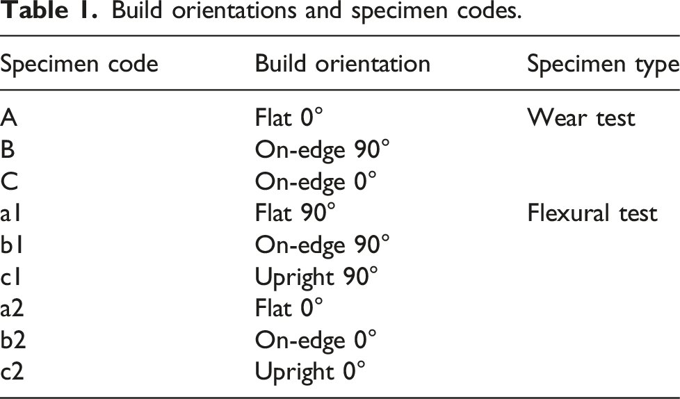
Build orientations and specimen codes.
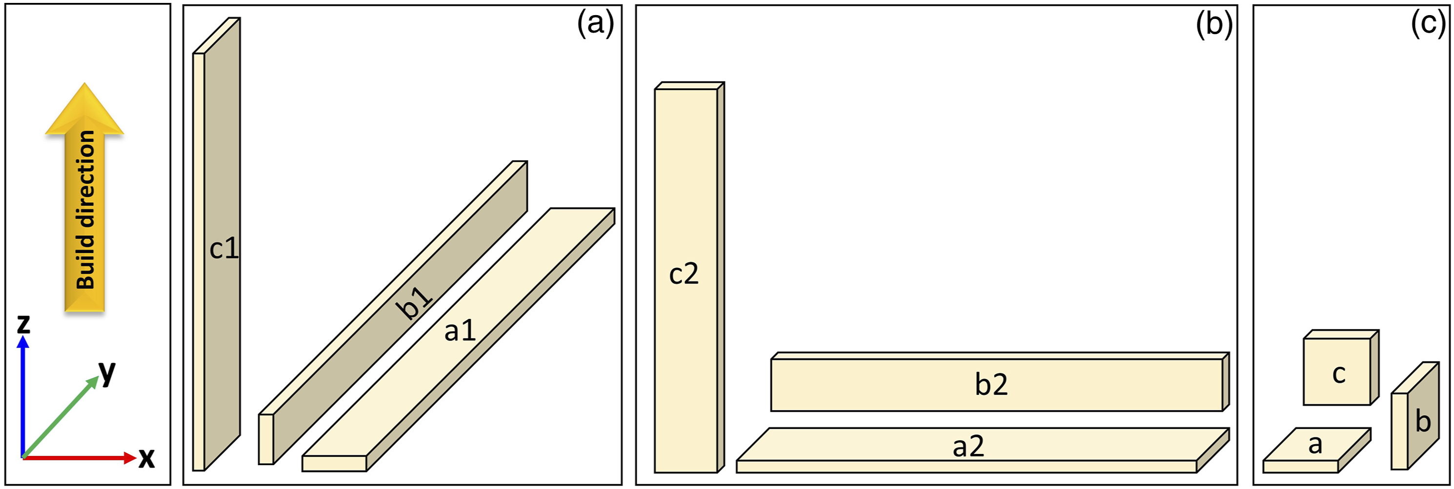
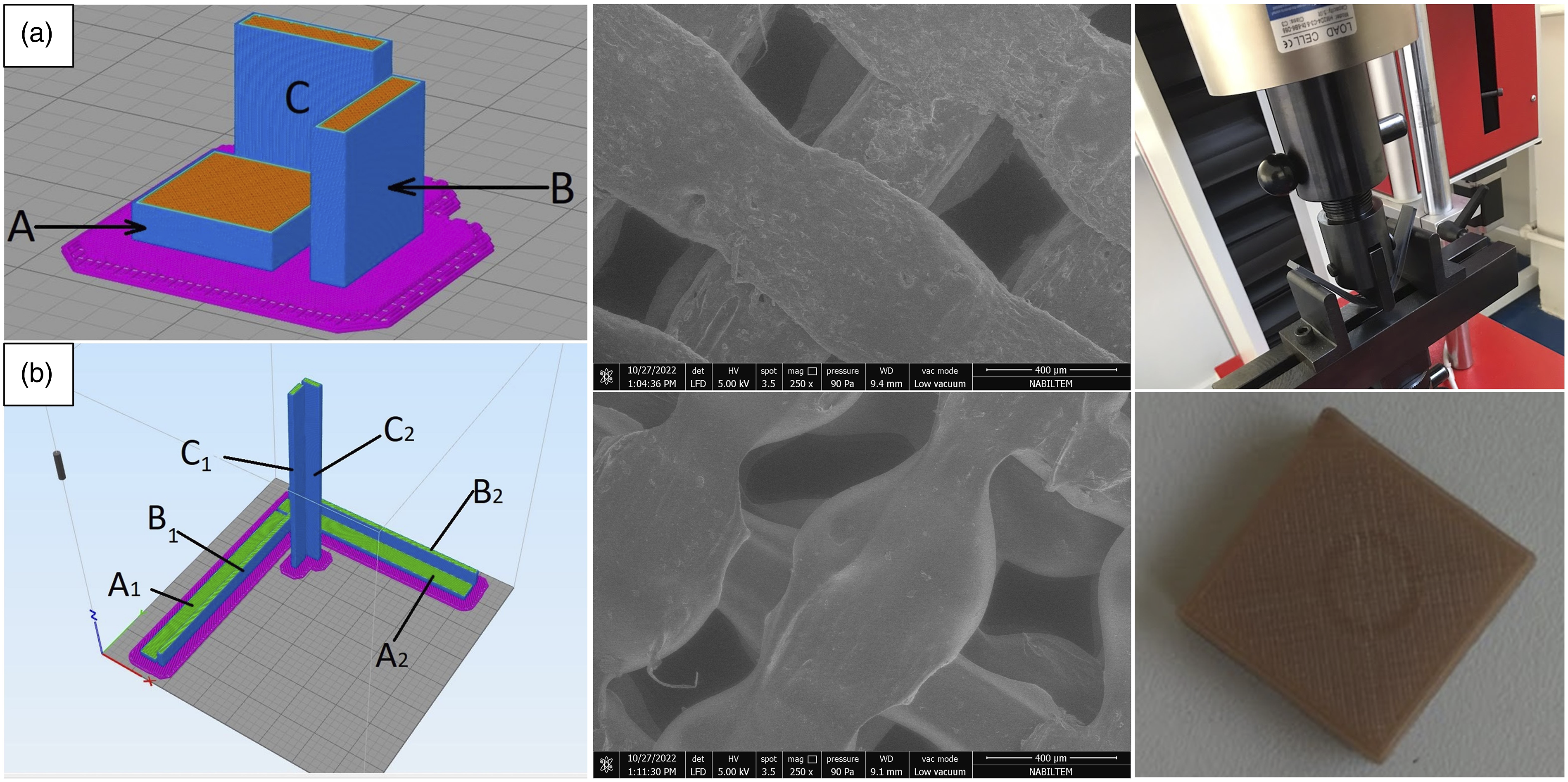
Build orientations of FDM-printed specimens for bending tests; (a) a1, b1, and c1 orientations, (b) a2, b2, c2 orientations, and for wear tests; (c) a, b, and c orientations.
Test methods and characterization
Dry and wet sliding properties of specimens are investigated using a ball-on-disk tribometer (Turkyus tribometer, Turkey) according to ASTM G99-17 standard. Alumina ball is selected as counter-face and it has 6 mm diameter, 99.5% purity, 3.86 g·cm−3 density and HV1410 hardness. Wear tests are performed using sliding speed of 25 mm·s−1 for a sliding distance of 150 m under an applied load of 15 N for 7 mm wear track diameter. Dry wear tests are performed at room temperature (RT); and wet wear tests are performed in a saline water medium (3.5 wt.% salt dissolved in deionized water) at RT. Test parameters are kept constant for dry and wet wear tests. Bending tests are accomplished using a compressive test apparatus with 5 kN capacity. Test speed is determined as 2 mm·min−1 and a pre-load of 1 N is applied. Microscopic characterization and elemental analysis of the worn specimens are accomplished using a SEM (Fei Quanta Feg 250) equipped with an EDS detector.
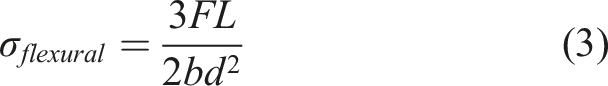
Wear rate, flexural strength, and flexural modulus calculation
Volume loss and wear rate values of worn specimens are calculated using equations (1) and (2) where Vloss is the volume loss, R is the wear track radius, r is the ball radius, d is the wear track width, W
R
is the wear rate, L is the sliding distance and p is the applied load

Results and discussion
Examination of as-printed surface and elemental analysis of filler particles
Top surfaces of FDM-printed specimens are examined, and micrographs are illustrated in Figure 2. Internal air gaps are detected between deposited rasters for copper, brass, and tungsten-filled PLA specimens. It is reported
40
that filler material addition to base polymer may increase the overall viscosity of melted filament during deposition process. Even if the infill density is kept at 100%, air gaps occurred in the intersections which can be attributed to the filler effect on polymer viscosity.41,42 Ji et al.
43
also observed air gap on the surface of Cu-filled PLA part with 100% infill density. Air gaps in the intersections can be associated with filler concentration, nozzle blockage of fillers, and inadequate extrusion power through the nozzle.44,45 Also, it is stated
46
that increase in filler ratio deteriorate dimensional tolerances. Subsequently, defects such as air gaps decrease the mechanical properties of printed specimens.
47
Various fillers differently affected the melted filament’s distribution over previously deposited layer. Copper, brass, and tungsten-filled PLA filaments formed large internal air gaps between rasters compared to bronze and carbon fiber fillers. Surface examination of as-printed PLA samples with (a) copper, (b) bronze, (c) carbon fiber, (d) brass, (e) tungsten fillers.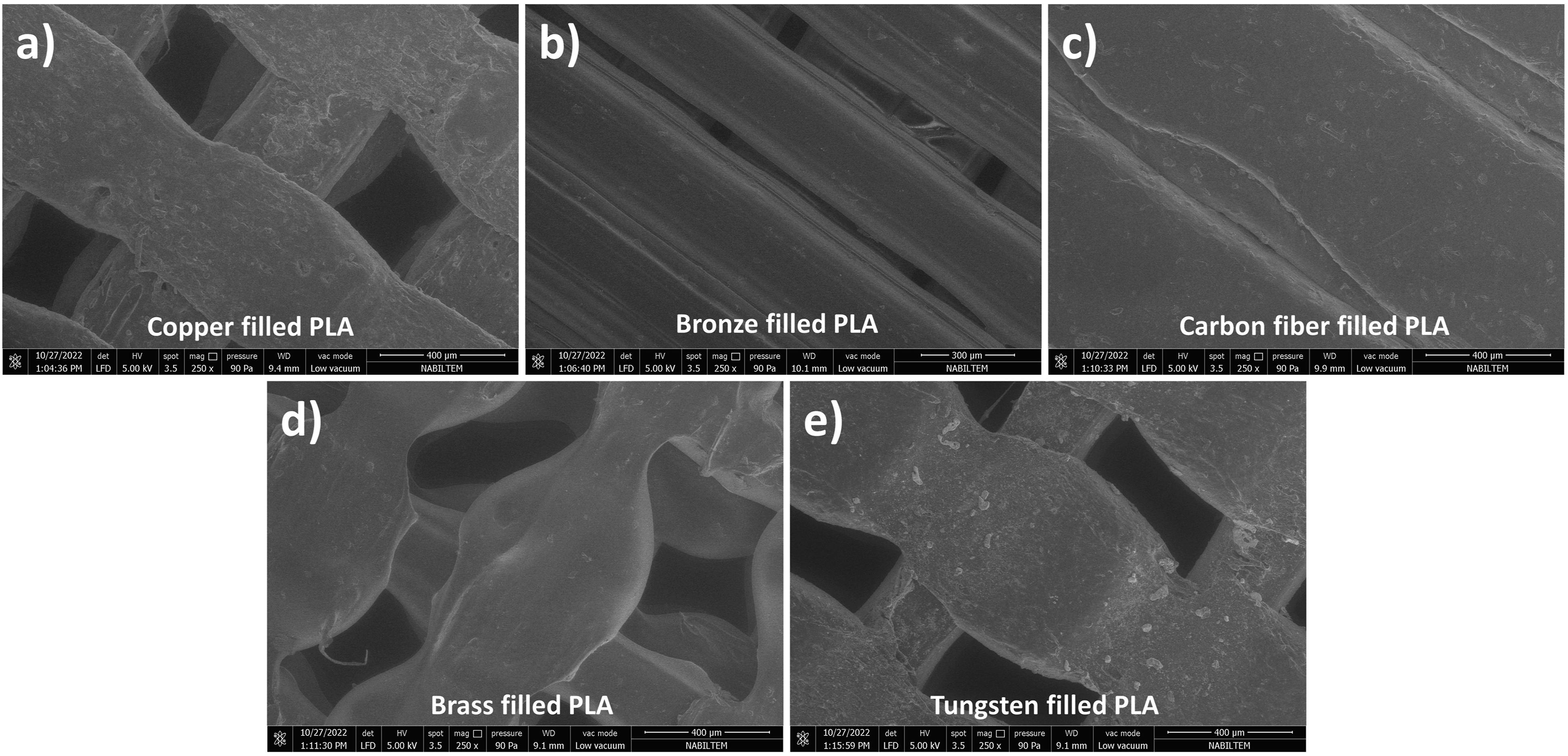
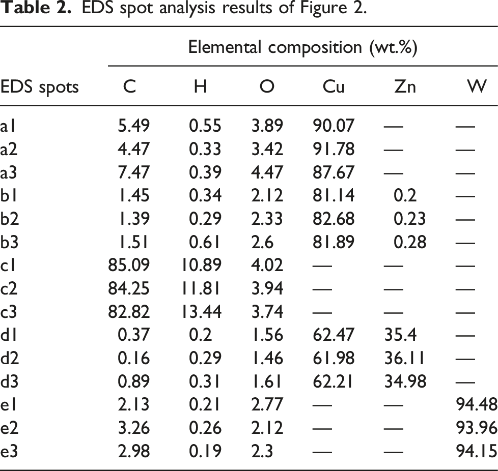
Specific spots on the specimens’ surfaces are subjected to elemental analysis and the results are depicted and tabulated in Figure 3 and Table 2, respectively. The particles on the surfaces of composite PLA parts are analyzed for each FDM-printed specimen. Copper and tungsten particles are identified easily in the analysis due to their one-element structure. However, brass, bronze, and carbon fiber particles are analyzed in detail according to their composition elements. Due to the C, H, and O composition of PLA matrix, all results include a certain amount of matrix elements and compatible with the literature
48
in terms of expected basic elements in the matrix. It is showed that filler materials coincide with the analysis results in Table 2. EDS spot analysis of (a) copper, (b) bronze, (c) carbon fiber, (d) brass, (e) tungsten-filled PLA surfaces. EDS spot analysis results of Figure 2.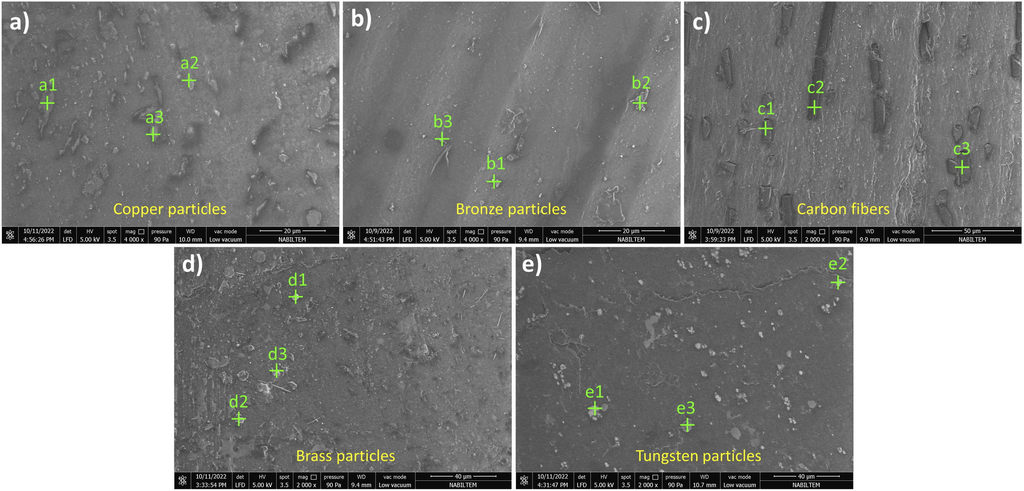
Wear track evaluations
Wear specimens are printed in different build orientations and subjected to rotational wear test in dry and wet sliding conditions. Wear behavior of surfaces are investigated to reveal the effect of sliding condition on build orientation. Also, effect of filler material is shown in terms of build orientation and sliding condition. SEM micrographs of brass-filled PLA parts are illustrated in Figure 4. In dry sliding condition (Figure 4(a), 4(b), 4(c)), main wear mechanism is smooth abrasive wear in which small particles of debris in flat 0° and on-edge 90° orientations and cyclic friction related cracks in on-edge 0° orientation are observed. A harsher abrasive wear behavior is detected in c orientation which can be attributed to on-edge 0° orientation on the print bed. In the on-edge 0° orientation, the print roughness is dominant on the large surface so that cyclic friction deforms the weak interlayer adhesion on the surface and cracks occur. A similar wear behavior is not observed for on-edge 90° orientation which can be attributed to transversal orientation against abrasive ball. In wet sliding condition (Figure 4(d), 4(e), 4(f)), mostly fatigue wear related characteristics are seen such as fatigue wear zones, pitting and spalling. The saline water medium lowered the severeness of abrasive wear and repetitive smooth friction started to loosen the particles on the surface. Herewith, loosened particle left the surface so that pitting and spalling mechanisms are observed. SEM micrographs of FDM-printed brass-filled PLA parts for conditions of (a) dry and orientation a, (b) dry and orientation b, (c) dry and orientation c, (d) wet and orientation a, (e) wet and orientation b, (f) wet and orientation c.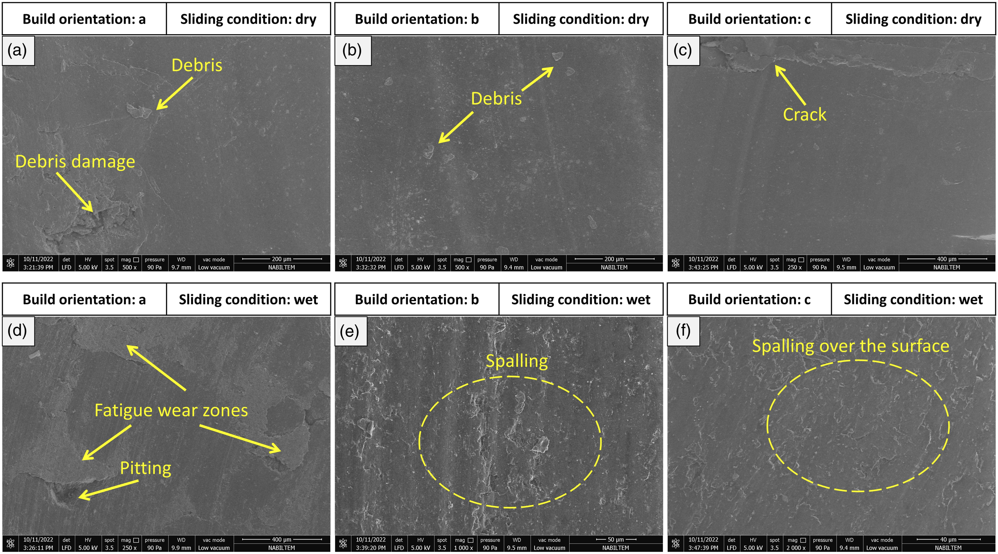
Wear tracks of bronzed-filled PLA parts are observed in the SEM and micrographs are provided in Figure 5. Figure 5(a), 5(b) and 5(c) correspond to wear tracks in dry sliding condition. Abrasive wear-based wear behavior is seen in the dry sliding condition which are grooves. Grooves are developed after dragging of debris or broken particles by the motion of abrasive ball on the wear track. Its magnitude depends on the hardness of debris, applied load and sliding speed. In Figure 4(a), openings are detected on the wear tracks which are formed between adjacent lines. Applied friction deformed the surface and weak interlayer bounds are broken. Weak interlayer bound results after poor cooling of previous deposited line or thermal shrinkage.
1
In wet sliding condition, smooth abrasive wear mechanism transformed to a mixed abrasive-adhesive wear mechanism. Plowing mechanism dismantled the embedded bronze particles so that delamination took place with the cyclic friction forces on the cavities of dismantled bronze particles. Stronger bonded bronze particles in the PLA matrix did not leave the surface so they are abraded by the abrasive ball’s repetitive motion. In terms of build orientations, flat orientation provided lower resistance against wear, however, orientations of on-edge 0° and 90° resisted against friction and a poor abrasive wear occurred. SEM micrographs of FDM-printed bronze-filled PLA parts for conditions of (a) dry and orientation a, (b) dry and orientation b, (c) dry and orientation c, (d) wet and orientation a, (e) wet and orientation b, (f) wet and orientation c.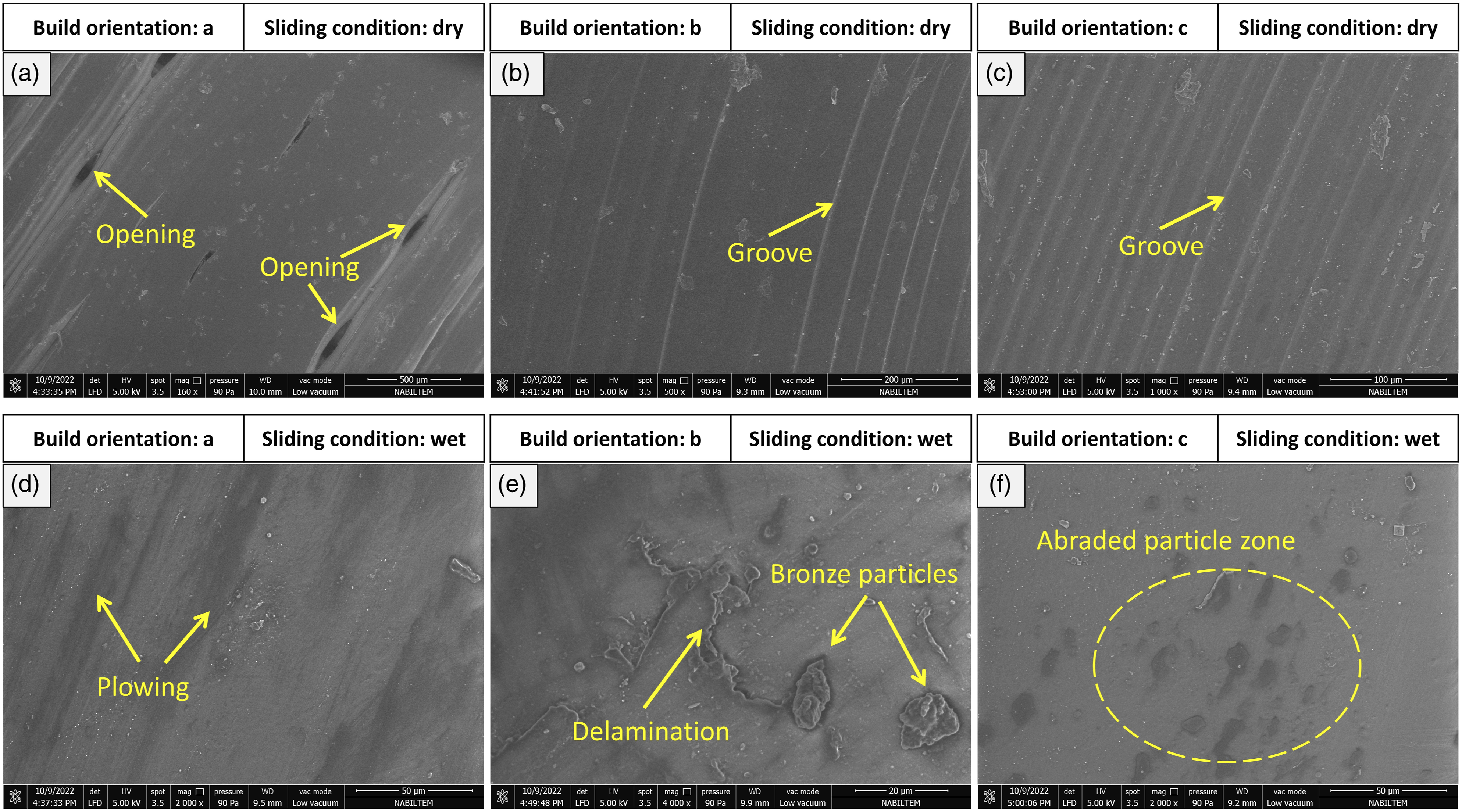
Figure 6 illustrates wear track morphologies of carbon fiber-filled PLA parts for dry and wet sliding conditions. As dry sliding condition (Figure 6(a), 6(b), 6(c)) shows that a smooth abrasive wear is present in which mild plowing occurred in the wear tracks. Besides, abraded surface edges formed ridges along the plowing lines. The repetitive friction abraded mildly the wear track and the abrasion allowed carbon fibers to show up as in Figure 6(c). In the wet sliding condition, a mixed wear behavior developed which is composed of mild abrasive and adhesive wear. Delamination is resulted based on adhesive wear, but carbon fiber pullout is related to abrasive wear. After some time in abrasive wear, alumina ball is covered with polymer particles, and it starts to develop adhesive mechanism. Cyclic adhesive friction loosens fibers in the surface and the amount of carbon fiber pullout increases. In terms of build orientation, flat orientation provides better interlayer adhesion between the deposition lines so that smoother wear track is obtained. On the contrary, on-edge orientations have lower interlayer adhesion and higher roughness on the surfaces which are suitable for wear. That is why, harsher wear mechanisms are observed for on-edge oriented specimens (Figure 6(b) and (c)). SEM micrographs of FDM-printed carbon fiber-filled PLA parts for conditions of (a) dry and orientation a, (b) dry and orientation b, (c) dry and orientation c, (d) wet and orientation a, (e) wet and orientation b, (f) wet and orientation c.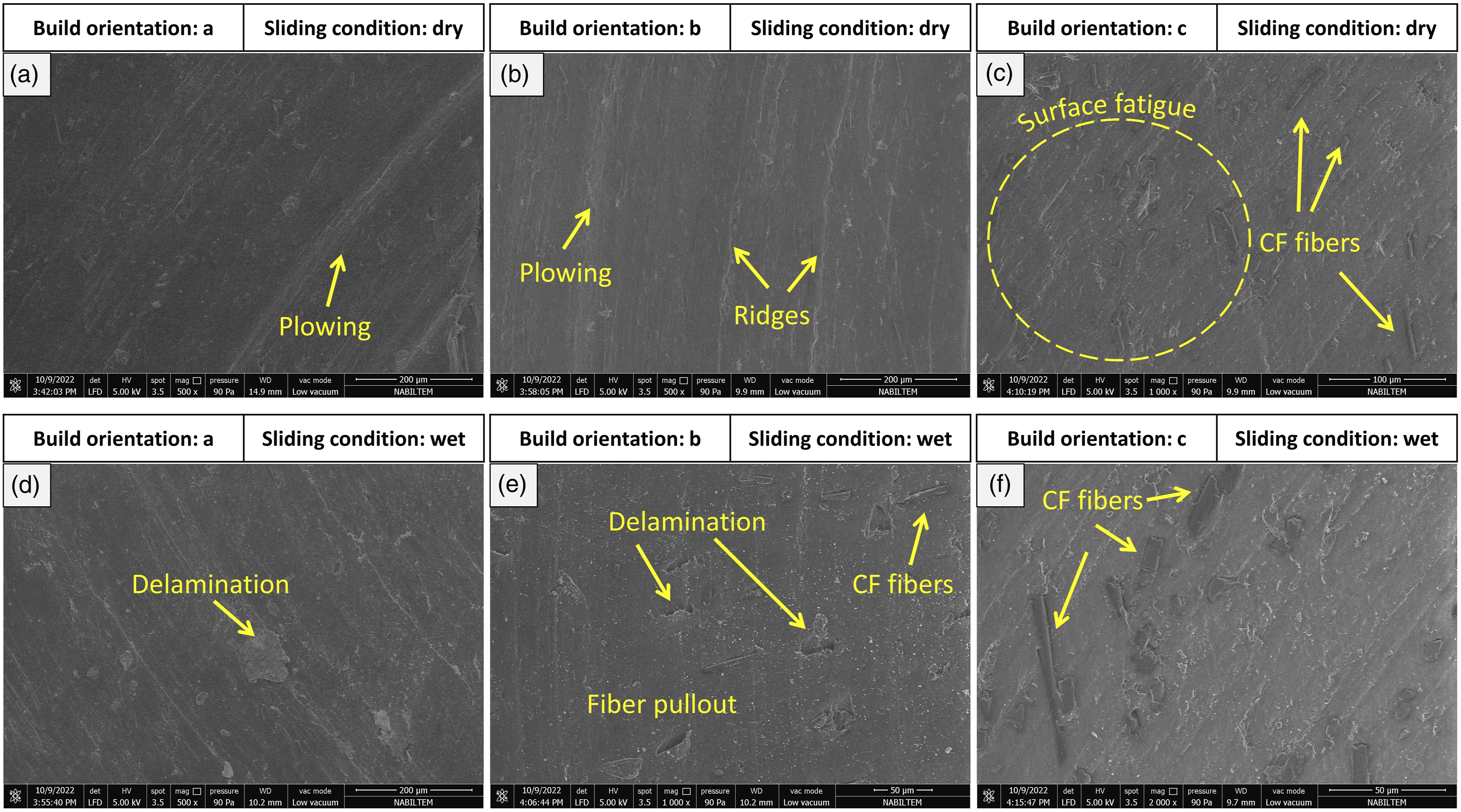
Figure 7 depicts the wear behavior of copper-filled PLA specimens in dry and wet sliding conditions. Debris and grooves are detected over the surface and pitting occurred. In dry sliding condition, after a cyclic abrasive deformation over the wear track, grooves are formed, and pitting mechanism takes place when the debris adhere to the alumina ball and pull the loosened particles out of surface. Unlike, abrasive wear mechanism also occurred in the wet sliding condition in which grooves, scars and pitting are observed. Cracks resulted in voids which can be attributed to deposition line intersections where adhesion is weak. Wet medium lowered the effects of friction on the surface, but fretting behavior is also seen which is mostly related to tribo-corrosive wear mechanism. Sliding condition is not related to wear behavior, abrasive wear is the only mechanism for copper-filled PLA specimen. However, build orientation has a slight difference in wet sliding condition in which flat orientation provided weaker wear surface so that voids and cracks are formed due to low adhesion between layers. SEM micrographs of FDM-printed copper-filled PLA parts for conditions of (a) dry and orientation a, (b) dry and orientation b, (c) dry and orientation c, (d) wet and orientation a, (e) wet and orientation b, (f) wet and orientation c.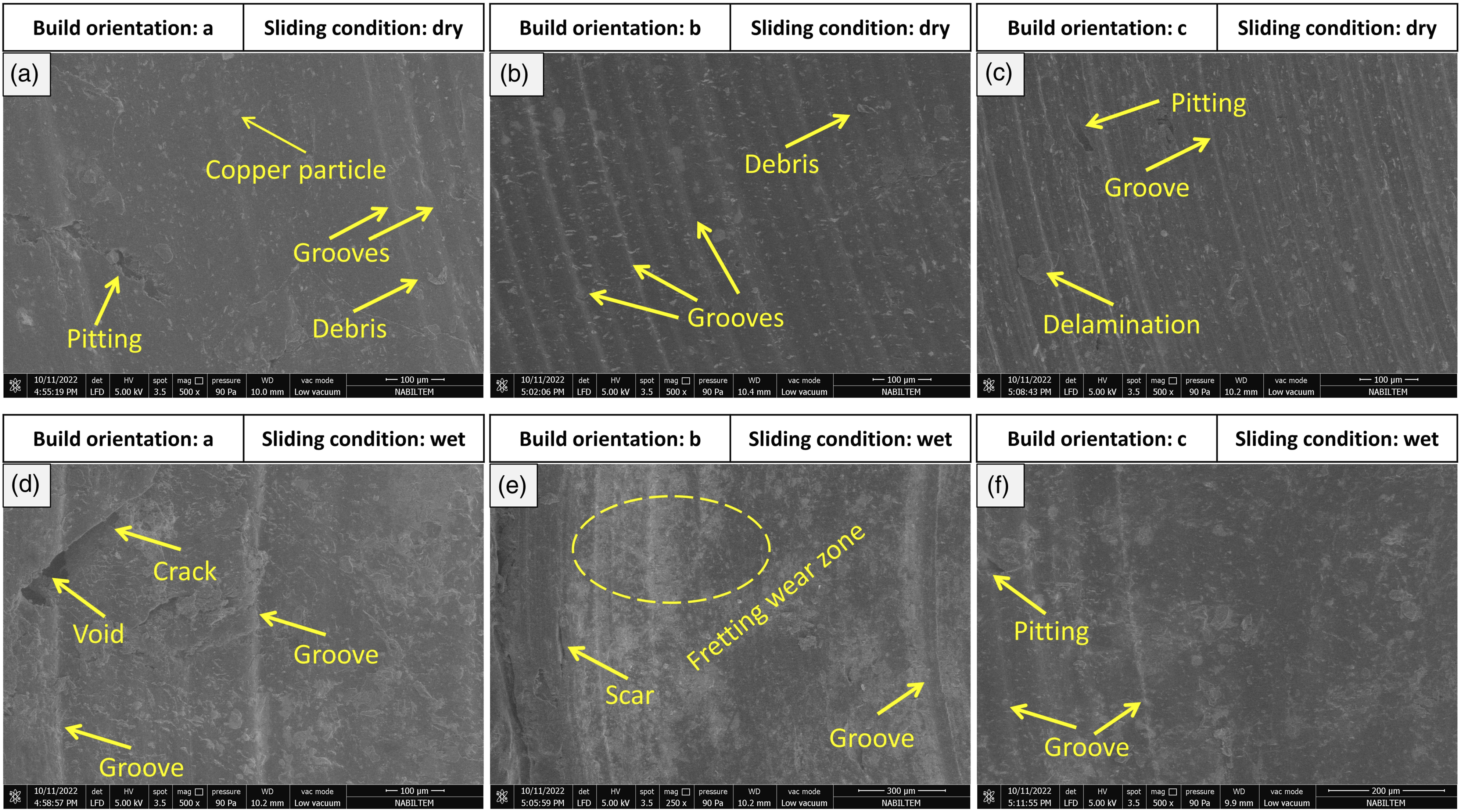
Figure 8 illustrates wear track morphologies of tungsten-filled PLA specimens in dry and wet sliding conditions. Mixed wear behavior is observed in dry and wet sliding conditions. Debris and delamination are seen on wear tracks along with fatigue and spalling zones. Cyclic friction on the surface enabled microcracks and resulted in sub-surface deformation and polymer flakes are peeled off from the surface. As a result, spalling and fatigue zones are formed over the wear track. Due to tungsten's hardness, microcracks involved in the formation of delamination. Adhered particles to the ball scratched the wear track and mild grooves are also formed. After repetitive abrasive friction on the surface, adjacent deposition lines which have weak adhesion revealed openings. In dry sliding condition, build orientation has not influence on wear behavior, but on-edge 0° orientation resisted against wear so that only mild grooves are occurred. SEM micrographs of FDM-printed tungsten-filled PLA parts for conditions of (a) dry and orientation a, (b) dry and orientation b, (c) dry and orientation c, (d) wet and orientation a, (e) wet and orientation b, (f) wet and orientation c.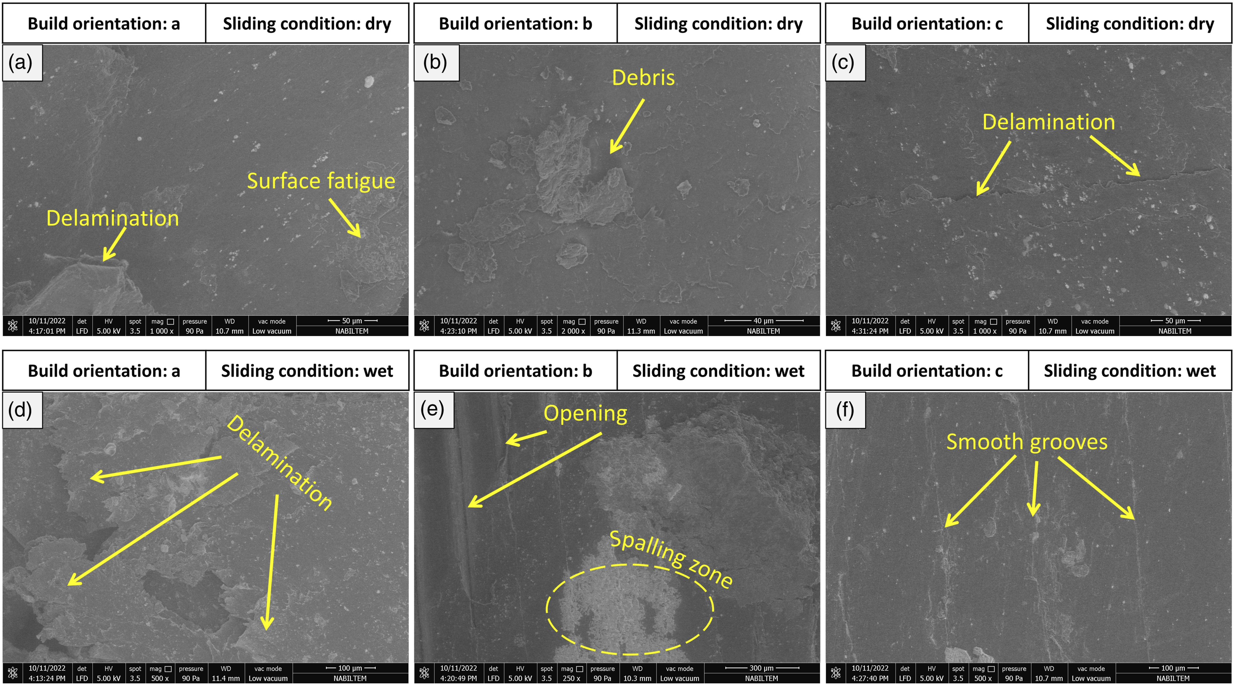
Results are compared with the current literature. Ertane et al. 49 revealed that FDM-printed PLA surrounds the filler material in the matrix and enables interlocking so that resistance against wear of composite is improved. In the current study, fiber and particle fillers are strongly bonded to the PLA matrix. It is mentioned that void appearance depends on the amount of filler volume in the matrix. But it is also stated 50 that void formation mechanism is a result of various parameters such as nozzle size, nozzle shape, melt flow velocity, bed temperature, and cooling rate. Wear modes in this study such as scar, pitting and grooves are also observed in another study. 51
Specific wear rate
Specific wear rate values of composite PLA parts are calculated, and results are illustrated in Figure 9. In dry sliding condition, the most wear resistant orientation is flat 0° which provided lowest specific wear rate values for all fillers except tungsten. It is showed
36
that highest mechanical strength is obtained with on-edge orientation for bronze-filled PLA specimen. It can be related to good bonding of layers during deposition process, successful cooling of previously deposited layers, low roughness on the surface, and low shrinkage on the wear surface. As the build orientation changes from flat 0° to on-edge 90° and on-edge 0°, wear resistance lowers which can be the result of rough surface for wear, impurities at the end of each deposition lines, and thermal shrinkage. Impurities at the end of deposition lines form an unstable layer which is a rough surface. It can be concluded that best wear resistance can be obtained by flat 0° orientation in the dry sliding condition. On the contrary, there are not significant differences in the wear resistance of specimens in the wet sliding condition. This can be associated with lubrication effect of saline water. By means of lubrication, magnitude of friction lowers and wears resistance of the surface increases. It is concluded that build orientation is not a characteristic and significant parameter in the wet sliding condition for tribological investigations. Specifically, tungsten-filled PLA composite specimens have the highest resistance against wear for dry and wet sliding conditions. High hardness of tungsten provided rigidity and resisted friction in the wear test. Besides rigidity, polymer matrix enabled flexibility so that the effect of deformation is absorbed. However, filler materials which are softer and more ductile than tungsten cannot resist the friction as much and other filler materials yielded higher specific wear rate values. It seems that carbon fiber-filled specimen showed similar wear resistance for dry and wet conditions. It is also showed that
52
wear behavior of CF-filled PLA did not changed much for varied layer thickness and higher infill densities which is related to the strong bond between fibers and matrix. Specific wear rate values of FDM-printed composite PLA specimens for (a) dry sliding, (b) wet sliding.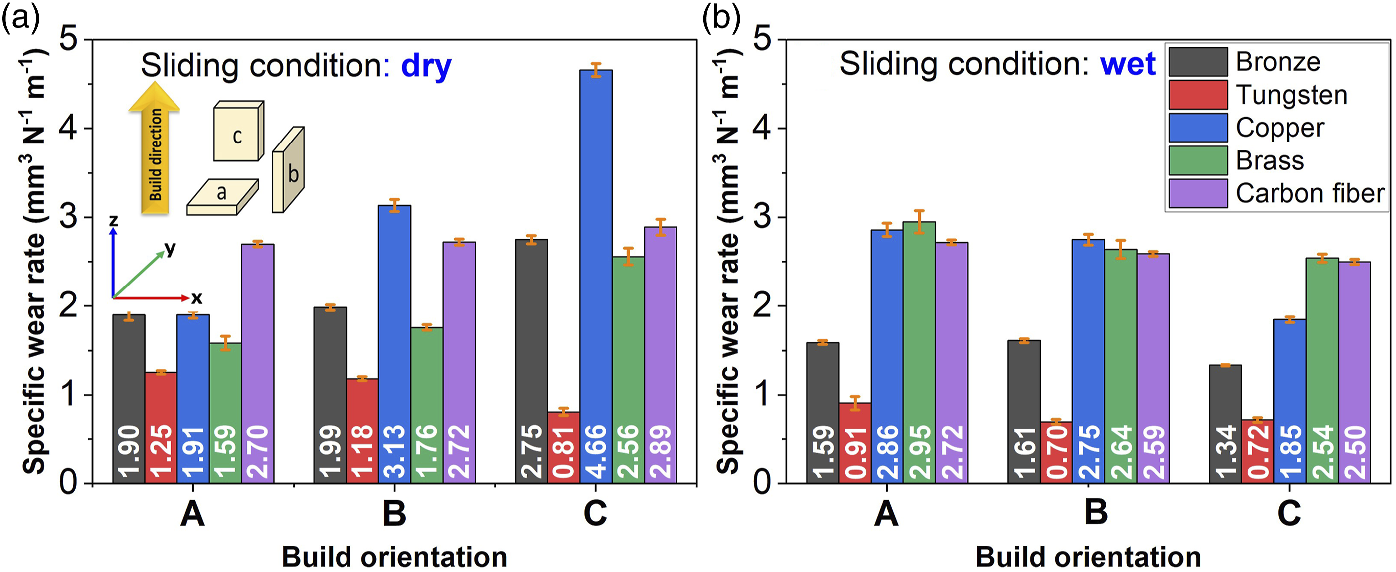
Coefficient of friction
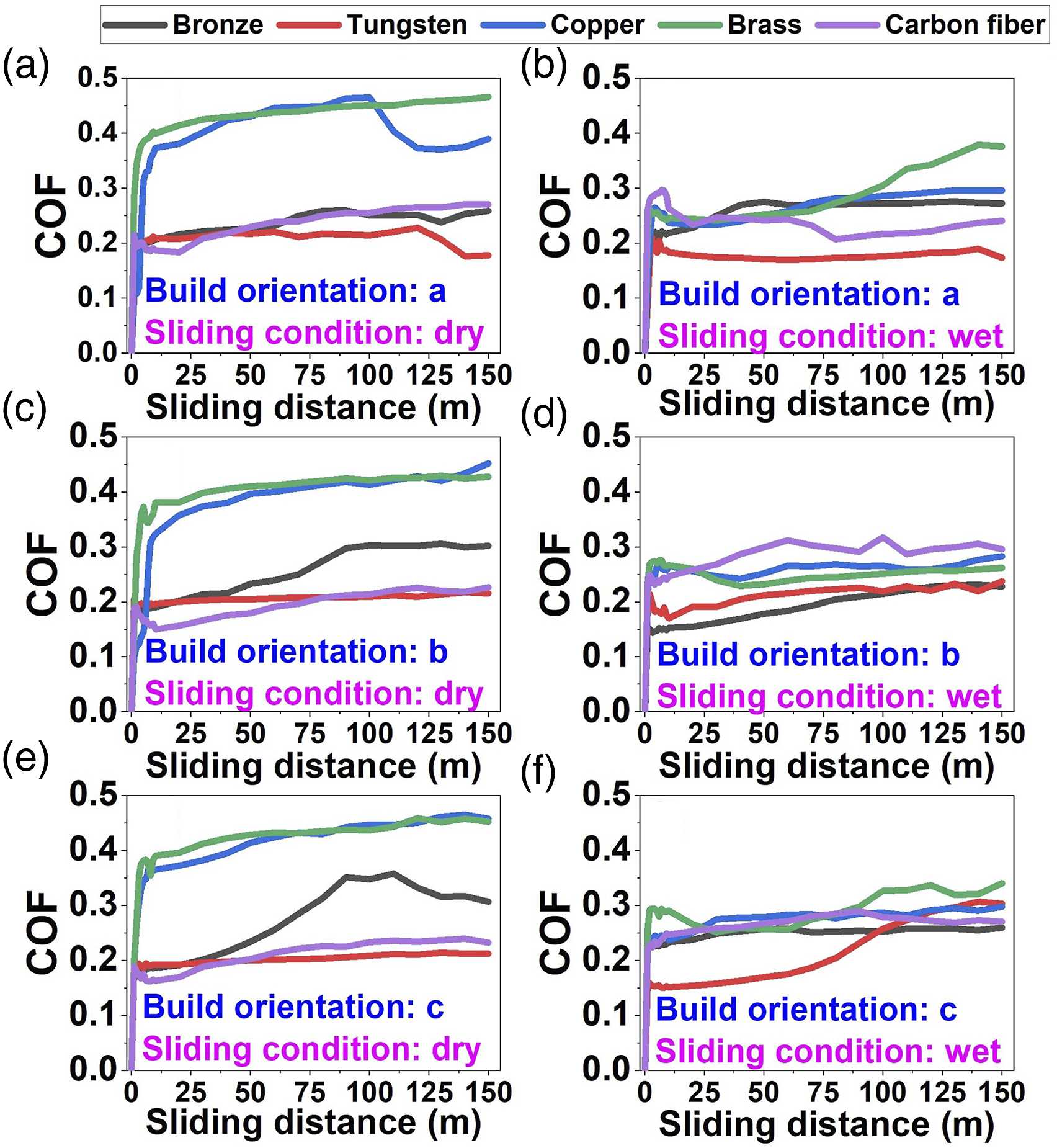
FDM-printed specimens are subjected to wear test and recorded coefficient of friction (COF) values are illustrated in Figures 10 and 11. Tungsten filler provided a stable COF value during tests due to its rigid, hard and wear resistant structure. In dry sliding condition, it revealed a constant COF value of 0.20, however there is fluctuations in the wet sliding condition which is associated with floating debris in the wear medium. Highest COF value is obtained with brass filler in the dry sliding condition for all orientations. Flexible structure of brass does not resist against friction and heat generation softens polymer surface which enables a rough friction surface so that a fluctuating COF value is recorded in the tests. Wet sliding condition lowered the COF value of brass-filled PLA, but it has highest COF values in flat and on-edge 0° orientation and second highest COF value for on-edge 90° orientation. Carbon fiber-filled PLA specimen provided lower COF value compared to bronze, brass and copper-filled specimens for dry sliding condition. High modulus of elasticity and high mechanical strength of carbon fiber maintained a balanced friction regime.
53
In wet sliding condition, balanced friction mode of carbon fiber-filled PLA specimen corrupted due to stuck particles of carbon fiber and polymer to the abrasive ball so that recorded COF values increased. Copper-filled PLA specimen showed one of the highest COF values which is attributed to low wear resistance and high ductility.
54
Lower COF values are recorded in the wet sliding test of copper-filled PLA specimen which can be attributed to good ductility properties and absence of pulled off particles in the wear medium. Bronze-filled PLA specimen had moderate COF value compared to other filler materials in the dry sliding condition. Alloying elements in bronze enabled a moderate balanced friction regime and resistance against wear is improved. In terms of build orientations, there are slight differences in average COF values for dry and wet sliding conditions. Mostly, COF values are decreased in wet sliding condition except carbon fiber-filled specimen which can be affiliated with water degradation of carbon fibers.
55
As it is seen, mechanical strength of metallic filler materials directly effects COF value in which durable filler materials reveal smoother friction. Besides, it is showed that filler materials affect the polymer crystallization characteristics
56
which results in altered mechanical properties. Average COF values of FDM-printed composite PLA specimens for (a) dry sliding, (b) wet sliding. COF values of FDM-printed composite PLA specimens for conditions of (a) dry and orientation a, (b) wet and orientation a, (c) dry and orientation b, (d) wet and orientation b, (e) dry and orientation c, (f) wet and orientation c.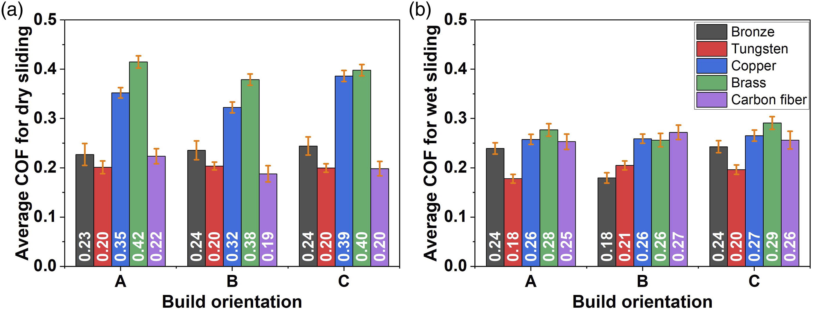
Flexural behavior
Three-point bending tests are applied and results of FDM-printed composite PLA specimens are illustrated in Figure 12. Brass-filled PLA specimens have higher flexural strength and modulus compared to other specimens. Brass filler’s ductile and durable properties improved its resistance against bending stress and higher flexural strength is obtained. Highest flexural strength and modulus are obtained with on-edge 0° and flat 90° orientations with 46.73 MPa and 1.53 GPa, respectively. Bronze-filled PLA specimens had highest flexural strength and modulus values after brass filler with 30 MPa and 1.40 GPa, respectively. Higher values can be attached with alloyed microstructure of bronze filler which has good mechanical properties. Its flexural strength and modulus are obtained with on-edge 0° orientation. Copper-filled PLA specimens have moderate flexural strength and modulus and on-edge 0° orientation provided highest flexural properties in the bending test with 28.57 MPa and 0.82 GPa, respectively. Compared with brass and bronze, pure copper had lower resistance against bending which can be the result of pure structure. Its ductile and flexible structure is not enough to overtake brass and bronze in bending tests. Carbon fiber-filled PLA specimens are only superior over tungsten filler in terms of flexural strength and has the poorest flexural modulus among other filler materials. Poor flexural properties can be attributed to anisotropic loading of specimens in the bending test. Carbon fiber may have not resisted the applied force perpendicular to the fiber orientation. Besides, carbon fiber orientation in the filament is not investigated so that mixed orientation of fiber in the PLA matrix may have formed a stress zone and notch effect lowered the flexural resistance. Hereby, on-edge 0° orientation provided the highest results for flexural strength and modulus with 24.81 MPa and 0.56 GPa, respectively. Tungsten-filled PLA specimens have the lowest flexural strength and modulus values compared to other filler materials which is associated with hard and rigid structure of tungsten. It is presumed that hard particles in the PLA matrix provided higher stress points during bending and cracks are developed which resulted in low flexural strength and modulus. However, highest flexural strength and modulus are obtained for on-edge 90° and upright 90° orientations with 21.92, respectively. Higher flexural strength and modulus values are obtained for on-edge 0° for most of the filler material. Build orientation effect are very obvious in bending tests which is attributed to high adhesion between layers. Short distance in the printing path enabled to compound of uncooled previously built layer and as-built layer which formed strong bonds between layers. Stronger bonds between rasters resisted against the applied load perpendicular to the specimen’s surface. Poorest build orientation is flat 90° which is related to the delamination during bending test. Printing path along the specimen’s longitudinal dimension did not resist the applied force and wear bonding between rasters are separated and delamination occurred. Shorter paths in the printing process of test specimens provides stronger bonds between rasters and layers so that higher strength properties are obtained in terms of bending test. As the distance of printing path is increased, poor bonding of previously built layer to the as-built layer takes place so that printing defects occur such as delamination, separation, and fracture. Increasing filler ratio in the matrix deteriorates flexural behavior of brass reinforced PLA due to lower interlayer adhesion energy.
35
Filler addition of 20% in the study seem applicable for flexural tests. Also, irregular shaped and heterogenous sized filler particulates generate notch-effect in terms of applied load. Notch-effect can be minimized by addition of regular shaped and homogenous sized filler materials. Flexural strength and flexural modulus of (a) copper, (b) brass, (c) tungsten, (d) bronze, (e) carbon fiber-filled specimens.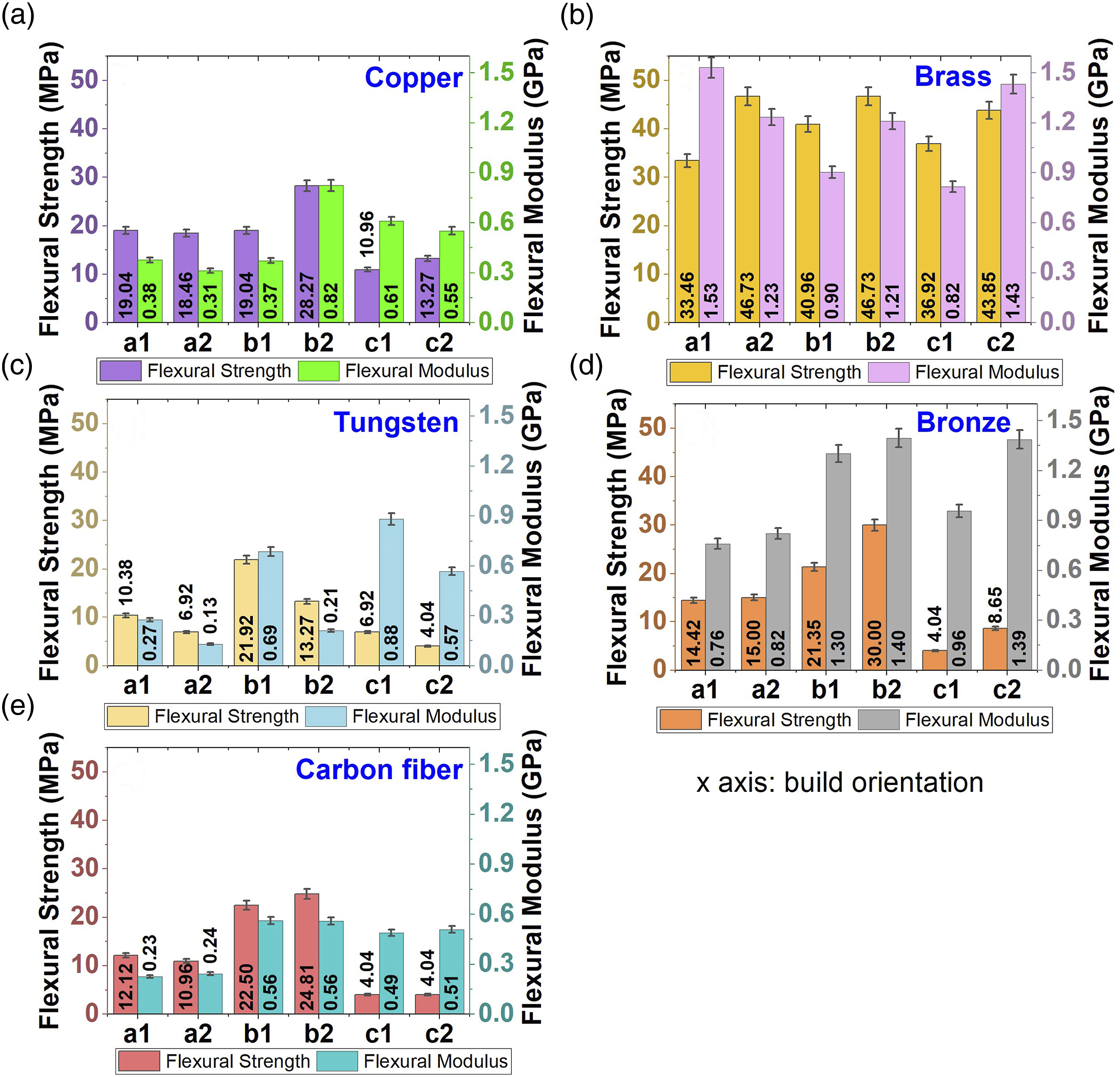
Conclusion
In the study, PLA filaments are used with various filler materials to print composite PLA parts for tribological and bending tests. SEM investigations, wear and bending tests revealed the following outcomes: • Distribution of melted filament on previously built layer has not big influence on the flexural properties of material. Because wide air gaps in the brass-filled PLA specimen provided the highest flexural resistance. For wear tests, air gaps in the raster intersections of tungsten-filled PLA specimen have not any influence on wear resistance. • Smooth or harsh abrasive wear is observed for the dry sliding condition, and adhesive, fatigue, and abrasive wear are determined for the wet sliding condition. • Wear resistance of FDM-printed specimens depends on wear medium. In dry sliding condition, the most wear resistant build orientation is flat 0° and it decreases with the orientations of on-edge 90° and on-edge 0°. In wet sliding condition, there is not significant variations in the specific wear rate values. • In terms of COF values, tungsten-filled PLA specimen revealed lowest COF while highest COF values are obtained with brass-filled PLA specimens in dry and wet sliding conditions. This can be affiliated with filler material’s mechanical properties. Brass particles are clinged to the abrasive ball and a rough wear is occurred and tungsten particles are hard and pulled out from the surface. • On-edge 0° orientation provided higher flexural strength and modulus values in the bending tests. Short deposition path enables stronger bonding in the rasters and provides resistance against applied load. • Build orientations are opposing for wear and bending tests in which on-edge 0° orientation allows stronger flexural properties while it is worsening the wear resistance. As a result, on-edge 0° orientation provides good flexural resistance and wear resistance can be obtained with flat 0° orientation. • Tungsten-filled PLA specimens are suitable for high wear resistant applications in dry and saline water environments. Bioinert structure of tungsten enables wear resistant applications which are possible in the biomedical industry. Also brass-filled PLA parts are proper to use in applications which require flexibility. This can be associated with composite PLA sheets for thermoforming process for various applications.
Footnotes
Declaration of conflicting interests
The author(s) declared no potential conflicts of interest with respect to the research, authorship, and/or publication of this article.
Funding
The author(s) received no financial support for the research, authorship, and/or publication of this article.