
Abstract
A stochastic morphological modelling framework has been established to predict the tensile behaviour of Randomly Oriented Strands made of ultra-thin Carbon Fibre Reinforced Thermoplastic prepreg tapes. The tape properties from their distributions are generated in a Monte Carlo simulation. The Young’s modulus of a laminate is accurately predicted using classical laminate theory. Fibre-dominant tensile failure is also accurately predicted in Carbon Fibre Reinforced Thermoplastics Sheet Moulding Compounds using Weibull theory. Material discontinuity is accounted for via the introduction of a stress concentration factor, as a result of tape overlaps. The predicted tensile strength values and scatter were found to increase with increasing tape length, which agrees well with literature data, and thus demonstrates the reliability of the proposed modelling framework. The rapid modelling framework is well-suited for application in structures.
Keywords
Introduction
Carbon Fibre Reinforced Thermoplastics (CFRTP) materials have received substantial consideration from the automotive industry due to their high-performance characteristics, low weight and convenient recycling ability. An advanced material called CFRTP Sheet Mounding Compounds (SMC) made of ultra-thin chopped carbon prepreg tapes, used for low-cost moulding of complex structures such as cars, has been studied at the Takahashi Lab.1–6 It is hereby referred to as CFRTP-SMC. The Takahashi Lab’s manufacturing methods significantly improved the strength of CFRTP-SMC by controlling moulding pressure and tape length. A fibre-dominant failure was consistently observed under tension.1,2,4,6 Compared with other existing SMC materials, such as Forged Composite® (Automobili Lamborghini S.p.A), 7 the CFRTP-SMC is twice as strong. Not only can CFRTP-SMC be recycled but it can also be made from waste materials such as prepreg off-cuts.
Despite the promising mechanical properties of this sustainable material, it is difficult to accurately predict their tensile strength without using complex numerical models due to the complex morphology of the Randomly Oriented Strands (ROS). The existing modelling methods for ROS have been reviewed by Visweswaraiah et al. 8 Morphological models which can represent the micro-structure of the ROS composites were developed for failure predictions. For example, Harper et al. 9 developed a geometrical modelling scheme to produce representative architectures for discontinuous fibre composites made of large fibre bundles. Based on the scheme, they used a detailed FE model to accurately predict mechanical properties such as tensile modulus and Ultimate tensile strength. Kravchenko et al. 10 developed a detailed Finite Element (FE) model for the prediction of tensile properties of stochastic Prepreg Platelet Moulded Composites (PPMC). The model can capture non-linearity of the PPMC material. Owing to their 3D nature, these FE models can be computationally expensive to run. Among the morphological failure prediction methods, there is one based on the ‘weakest-link’ principle which assumes that the weakest cross-section will break first, for example, see Nacre. 11 It has since been implemented to ROS by Pimenta and Robinson, 12 and Selezneva, 13 who successfully addressed interlaminar failure in ROS. However, experiments of the CFRTP-SMC material from the Takahashi Lab indicate fibre-dominant failures without global tape poll-outs in References 1,2, which are very different from the other ROS. This calls for a new modelling framework to address brittle failures in the CFRTP-SMC material. So far, models have been developed for the prediction of elastic moduli,3,5,14 but tensile failure has not been covered yet.
Although the ‘weakest-link’ principle was referred to by Selezneva et al., 13 the ‘weakest-link’ theory was originally introduced by Weibull 15 to explain size effects in solids. It assumes that when the weakest link in the chain breaks, the entire chain will fail, which makes it suitable for predicting brittle failure of solids. Sometimes referred to as Weibull theory, it was also implemented to explain size effects in continuous fibre composite materials. 16 The same theory was used to link the strength scaling in unidirectional, quasi-isotropic and open-hole quasi-isotropic continuous carbon fibre composites. 17 Weibull theory was then used as a fibre failure criterion for modelling fibre-dominant failure in continuous carbon fibre composites.18,19 To the authors’ best knowledge, Weibull theory has never been applied to a morphological model for the failure prediction of ROS.
This paper presents a stochastic morphological modelling framework for the tensile failure prediction of ROS. The model successfully predicts the fibre-dominant failure of the CFRTP-SMC material made of ultra-thin chopped prepreg tapes using Weibull theory. Material discontinuity is addressed by the introduction of a stress concentration factor induced by tape overlaps. The predicted Young’s modulus, tensile strain to failure and strength of the CFRTP-SMC laminate are cross-validated with experimental results obtained from literature. A parametric study is conducted for different tape lengths, and the results are compared with the available data to assess the robustness of the framework. The model is quick to run, so can be used when designing structures made of ROS that exhibit fibre-dominant failures such as CFRTP-SMC.
Experimental data
Material fabrication
Tape geometrical and material information.
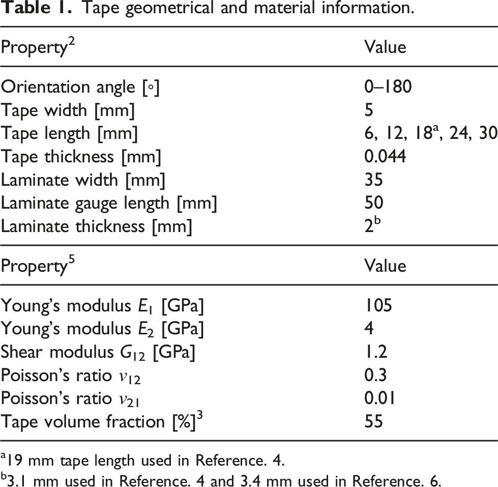
a19 mm tape length used in Reference. 4.
Tensile tests
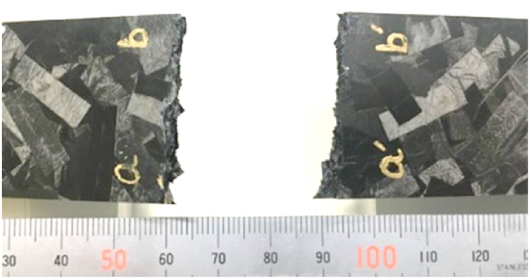
The current CFRTP-SMC laminate with ultra-thin chopped carbon tapes, which was also referred to as SM-1t CTT material, exhibited fibre-dominant tensile failure according to Wan et al.2,6 The brittle failure was examined through stress-strain response, acoustic emission and fractography examination by Wan et al.
6
Up to ultimate failure, the stress–strain curve was approximately linear. The acoustic emission hits also indicated limited damage until approaching the end. Furthermore, the broken specimen exhibited distinctive brittle fracture surface as shown in Figure 1.
6
Photo of a typical broken specimen showing fibre-dominated failure.
6
Modelling approach
Modelling assumptions and limitations
The current stochastic morphological modelling framework is established in
To achieve rapid tensile failure predictions, the following assumptions were made: the movement of chopped tapes, generation of defects, for example, voids and wrinkles during compression moulding are ignored; the chopped tapes can overlap without changing their morphology; the strength of the chopped tapes of different lengths is constant; and the model is 2D, but divided into ‘layers’ of ROS, which are introduced for the calculation of Young’s modulus and stress concentration factor.
The main limitation of the model is that it does not consider resin failures or the consequent tape debonding. It is suitable for the current CFRTP-SMC material but should be used with caution for other SMC materials.
Laminate generation and elastic response
The moulding area, where chopped tapes are randomly distributed, is a rectangle offset by the length of one tape t
l
from the boundary of the laminate, as displayed in Figure 2(a). The coordinates of each tape centre, x and y and its rotation angle θ, cf. Figure 2(b), follow uniform distributions with Geometrical information for (a) moulding and laminate areas (b) a tape.
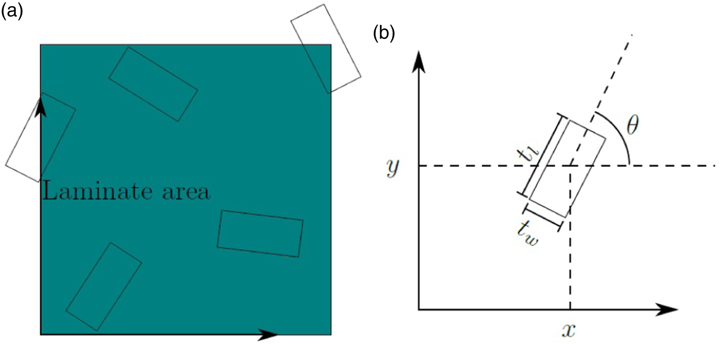
It is important to note that only the chopped tapes that fall wholly or partially inside of the laminate area are considered for calculation of the volume fraction, overlap area, etc. The volume fraction of the laminate, V
f
, is proportional to the ratio between the area filled by the chopped tapes and the laminate area, that is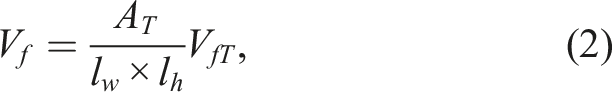


Although the current model is 2D and has no depth, the layer concept is introduced to assist the calculation of Young’s modulus and tensile strength. The laminate is divided into multiple layers, each of which has a thickness of t t , for example, a 2 mm–thick laminate has approximately 1/0.044; 44 layers.
The elastic stiffness matrix of the laminate has been formulated using classical laminate theory.
20
The stiffness matrix of an individual tape is defined as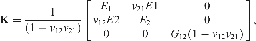

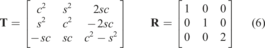
A force F applied to the laminate is related to its mid-plane strain ϵ and curvature κ by the following algebraic equation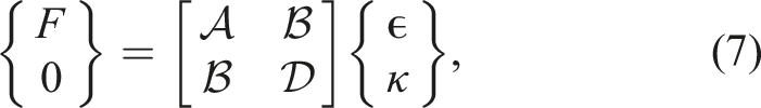
The force F is prescribed as a series of load increments, and translated into an applied nominal stress σ
N
, via the cross-sectional area of the laminate, that is,
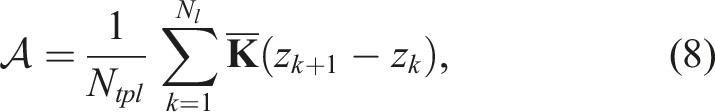
Equation (7) is used to find the corresponding mid-plane strain ϵ and curvature κ, which is then converted into the fibre-direction stress of the chopped tapes according to equation (11) in which z is the location of the ‘layer’ where the tapes are located
Weibull failure criterion
In the previous work by Xu et al.,
18
fibre failure in continuous fibre composites assumed an equal probability of survival between the model and a unit volume of material, and the adopted criterion was a function of both the volume and the stress through the Weibull integration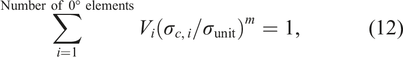
For the current CFRTP-SMC material which exhibits fibre-dominant failure, the same fibre failure criterion based on Weibull theory can be used. The fibre failure parameters are assumed as σunit = 3131 MPa and m = 41, based on a similar IM7 carbon fibres (Hexcel Co., US) reported by Xu et al., 19 but some modifications to equation (12) are required to address fibre discontinuity.
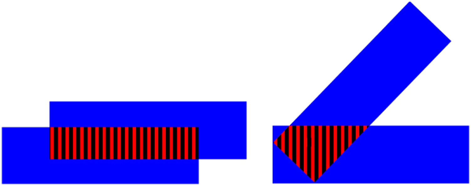
Chopped tapes with an angle smaller than 1° are identified (Figure 3). They are referred to as ‘critical tapes’. One degree is chosen because it is the typical fibre misalignment angle in fibre composite structures. These ‘critical tapes’ are expected to have the highest stress in the fibre direction, so most likely to fail. According to Weibull theory, the failure of these ‘critical tapes’, the weakest link, will trigger the failure of the laminate. Larger tape angles will be less critical due to less fibre-direction stress in them. According to equation (12), the fibre-direction stress will be raised to the power of m = 41, so its contribution to failure will reduce dramatically if the stress is less. Distribution of ‘critical tapes’ in blue in the gauge section of a tensile specimen.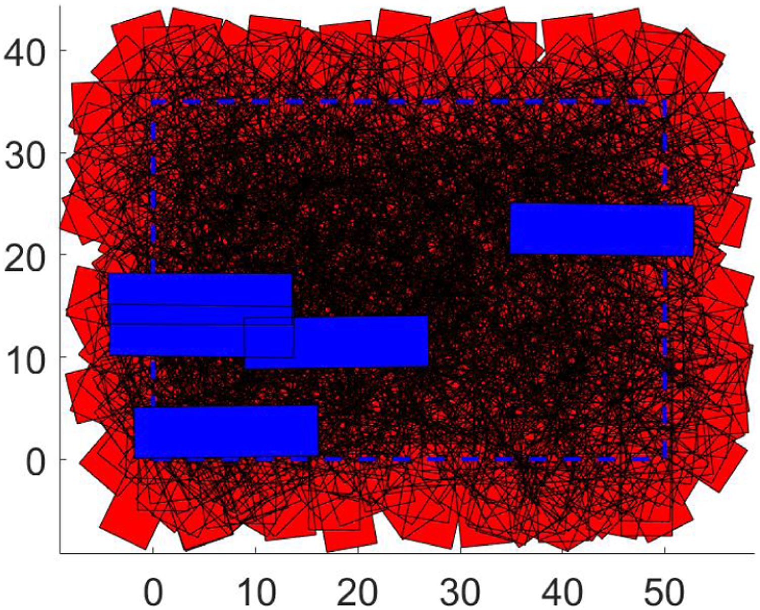
Within the range of these ‘critical tapes’, they are seen as continuous. The other angled tapes which touch these ‘critical tapes’ in each layer are seen as discontinuous. The force carried by the other angled tapes therefore needs to be transferred to the ‘critical tapes’. This results in an increase of stress in the ‘critical tapes’ through a Stress Concentration Factor (SCF). The SCF is defined as the ratio between the resultant loading-direction stress taken by the ‘critical tapes’ σ
c
, including those transferred from the overlapped angled tapes σ
a
, and the fibre-direction stress taken by the ‘critical tapes’, that is,
The resultant loading-direction stress in the ‘critical tape’ is calculated via the total force applied in a ‘critical tape’ F
t
, divided by its cross-sectional area, .that is, ‘Critical tapes’ overlapped with angled tapes in red hatched region.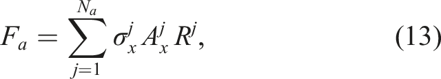
Finally,
For each ‘critical tape’, its fibre-direction stress will be updated by multiplying the SCF, and seen as a ‘0° element’ in equation (12). Then all ‘critical tapes’ are integrated in as a failure check. Once the condition in equation (12) is fulfilled, the strain to failure and tensile strength of the laminate, ϵ N and σ N , can be determined at the failure load step.
Modelling results
The current section highlights use of the proposed modelling framework to predict laminate tensile properties, such as the Young’s modulus, strain to failure and tensile strength. Results were compared against an experimental set from literature.
Predicted material fabrication properties
The contour plot shown in Figure 5(a) illustrates the regions where there are few layers (blue) and where there are an excessive number of layers (yellow) from a Monte Carlo simulation. The corresponding frequency distribution of number of layers is shown in Figure 5(b). This plot is based on 36 000 grid sample points which are uniformly distributed along the laminate area. After careful examination of the statistical distribution of tapes, the mean layer number is very close to the previously estimated value of 44 from equation (4). (a) Overlapping area based on number of layers contour plot and (b) corresponding histogram of number of layers.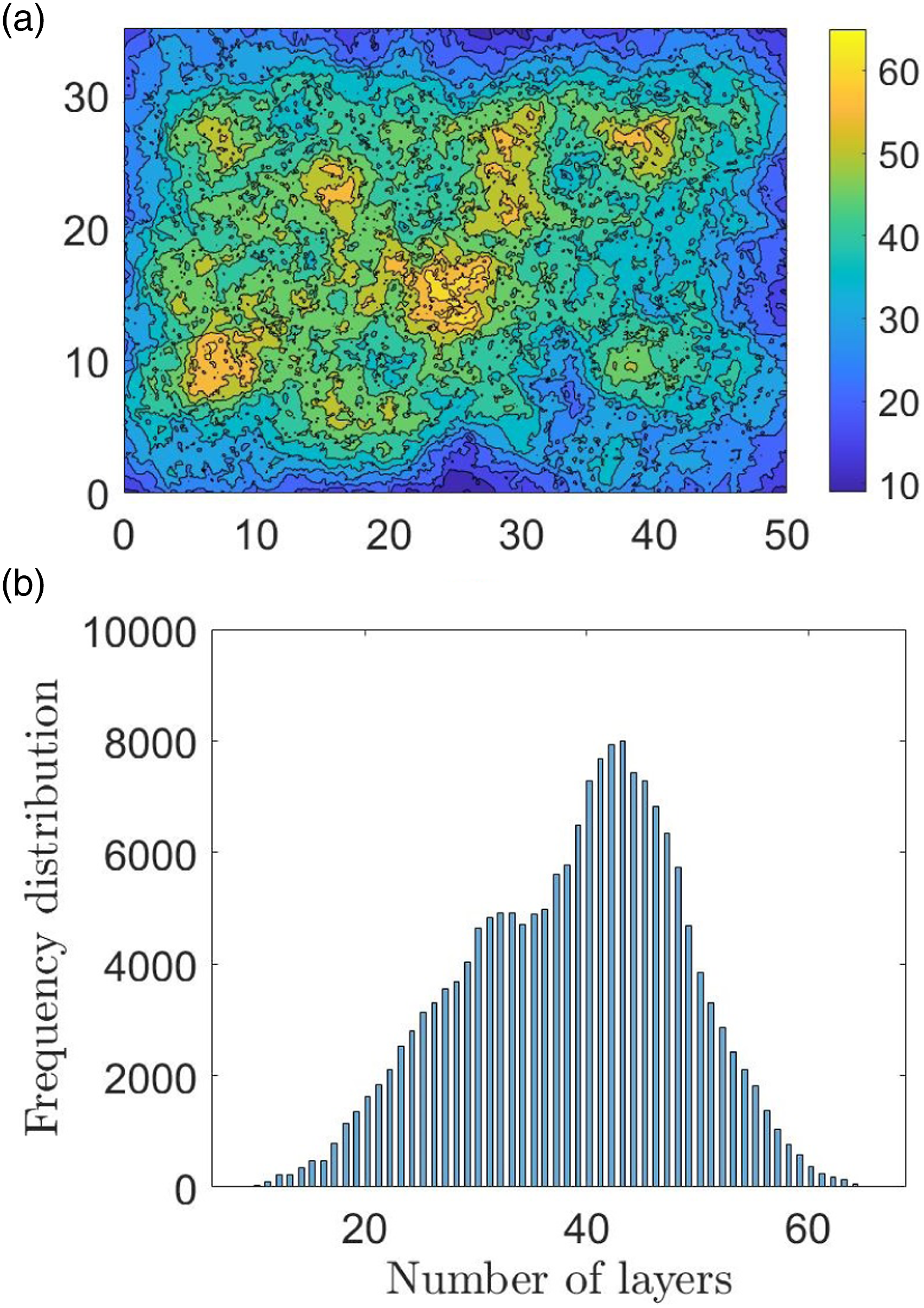
Predicted tensile properties
The current modelling results are compared against the available experimental results in the literature as shown in Figure 6. Here the tape sizes in the models were chosen as 19 × 5 × 3.1 [mm] and 18 × 5 × 3.4 [mm] to match the experiments in Reference 4 and 6, respectively. Each tape size has been sampled 20 times to account for the randomness of the fabrication process, which is well over the typical specimen number in experiments. Results comparison of (a) Young’s modulus (b) tensile strength.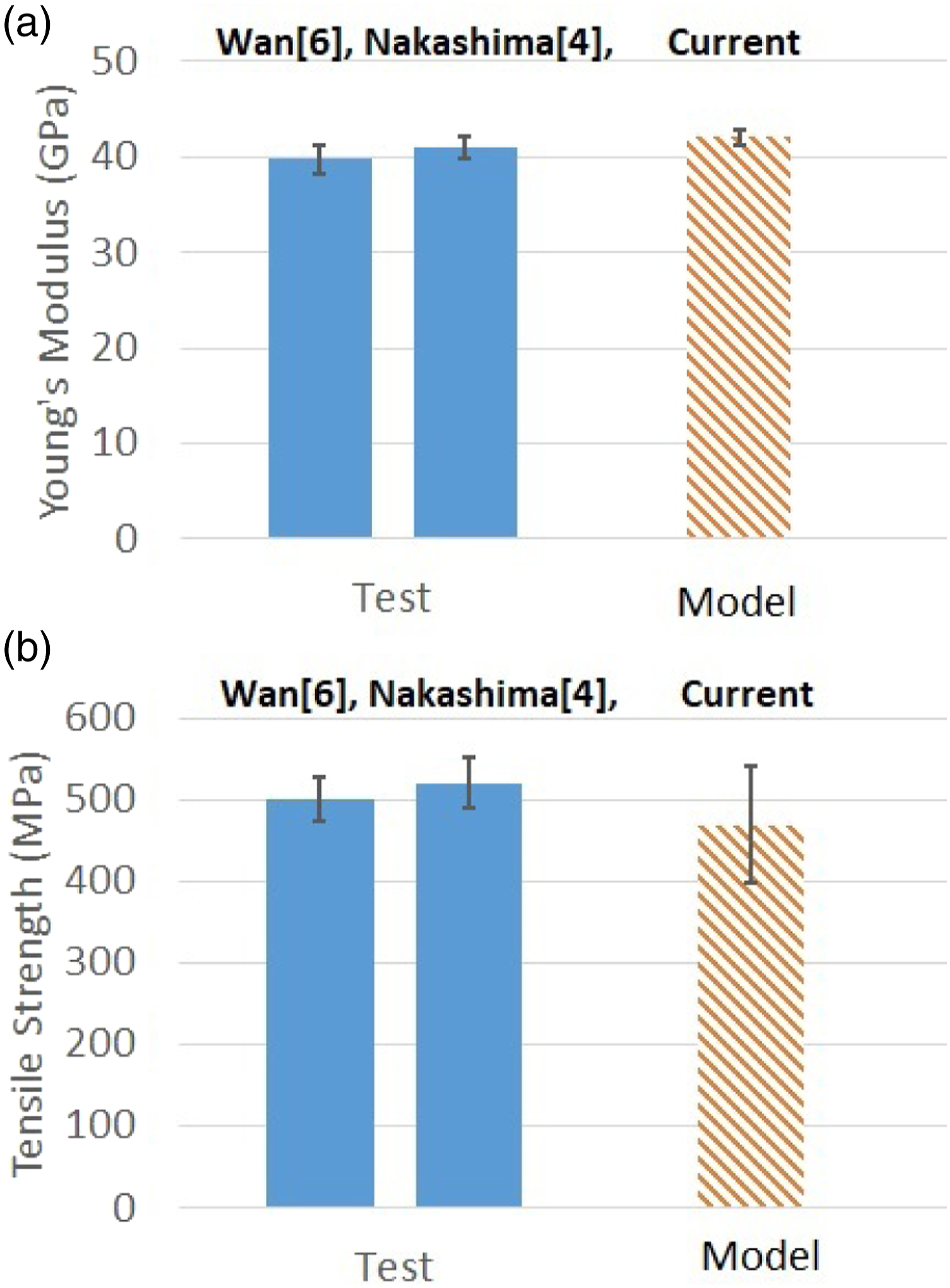
The predicted Young’s modulus correlates well with the experimental results in Nakashima et al. 4 and Wan et al. 6 The modelling and experimental scatter for Young’s modulus is not large. A small scatter is expected as the laminate would behave like an in-plane isotropic material if the tapes are randomly mixed, and the modulus is an average property of all tapes. Specifically, the predicted mean Young’s modulus is within 5.73% from the measured mean value by Wan et al. 6
The predicted tensile strength correlates well with the experimental results in Nakashima et al. 4 and Wan et al. 6 The modelling scatter for tensile strength is noticeably larger than in experiments. Due to the random nature of ROS, the test results of the same CFRTP-SMC material in the literature based on small sample sizes may not show the real scatter for tensile strength. If matching the model sample size, the scatter may correlate better. Specifically, the predicted mean tensile strength is within 6.27% from the measured mean value by Wan et al. 6 The measured values are mostly within the standard deviation of the modelling results.
A parametric study on tape lengths
A parametric analysis has been conducted to analyse the influence of tape size on tensile properties of the material. Five tape sizes (6 × 5, 12 × 5, 18 × 5, 24 × 5 and 30 × 5 [mm]) were considered. The modelled laminate thickness is 2 mm to match the experiments. 2 The run time for a total of 100 different configurations is 161 min by using one CPU.
As shown in Figure 7(a), the predicted Young’s modulus is within 4.27% of the average value of the experimental data (18 × 5 [mm]) reported by Wan et al.
6
The measured average values from2,6 always fall within the standard deviation of the simulations. In the parametric study, the Young’s modulus is insensitive to the tape size, which, however, does not agree with the overall trend observed by Yamashita et al.
2
This will be discussed later.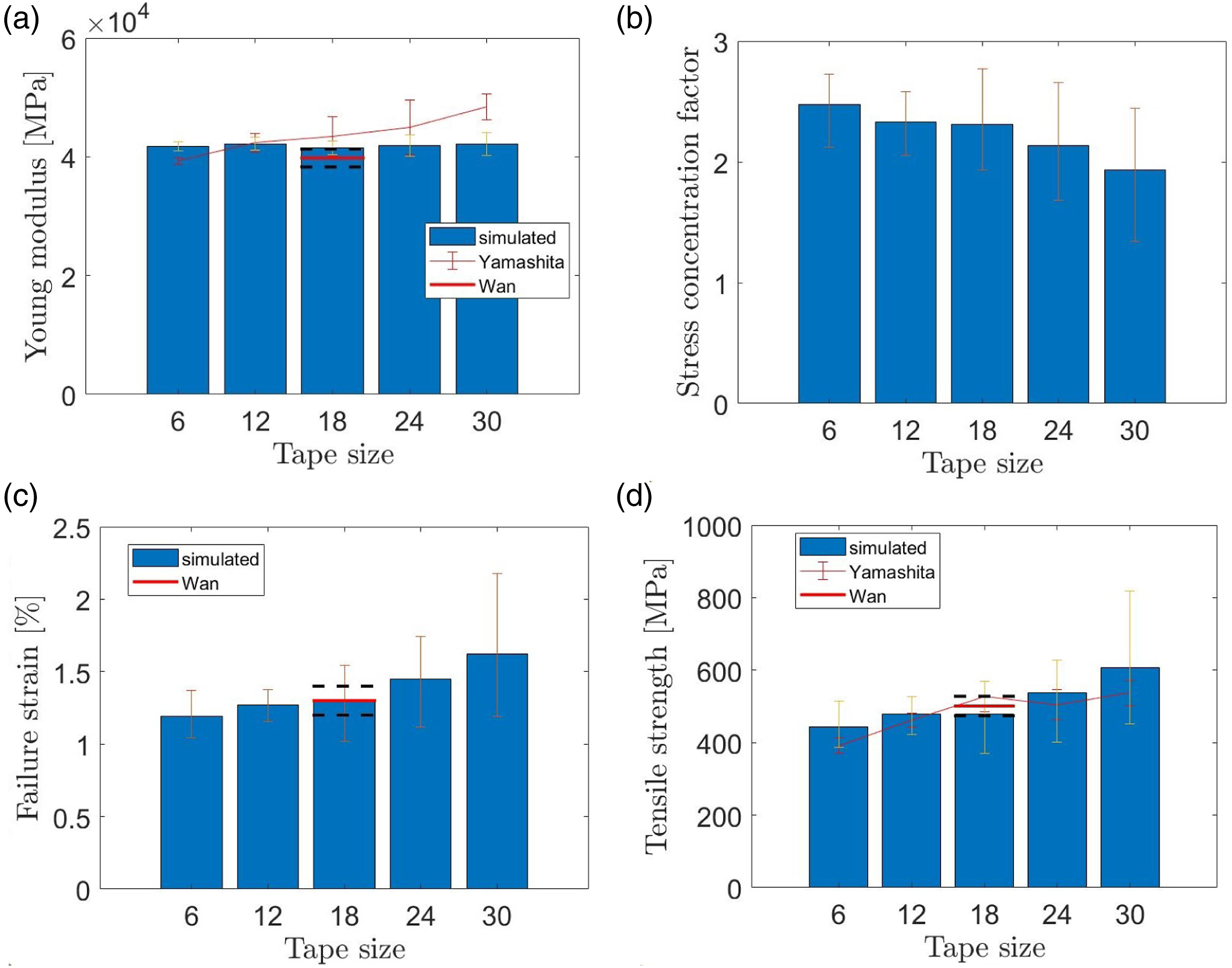
Agreement with experimental data, horizontal lines, is discussed with respect to the tape size (18 × 5 [mm]). 6 For strain to failure and tensile strength, there is a close agreement with the experimental average values (within 4.43% for 18 × 5 [mm]). The experiments scatter is mostly within the standard deviation of the simulations which is larger. In the parametric study, as the tape length increases the SCF decreases (Figure 7(b)), presumably because fewer and longer chopped tapes interact with each other less. As a result, both properties increased with the tape length as shown in Figure 7(c), Figure 7(d). Correspondingly, their variability also increased. The increasing trend is consistent with the literature reviewed by Visweswaraiah et al. 8. The predicted tensile strength values agree well with Yamashita et al. 2 as shown in Figure 7(d).
Discussion
The current model predicts an approximately constant modulus for laminates with different tape sizes, which is different from the experimental results in Reference 2. This may be because the current model ignores the change of fibre orientation during compression moulding, which might be influenced by different tape dimensions. Without considering material processing, and if the ROS are sufficiently mixed, the laminate is expected to be in-plane isotropic, so the laminate Young’s modulus is not dependent on tape dimensions in the current model.
The aspect ratio of the tape length to tape thickness was found to affect the tensile properties. 10 In the current work, since only one tape thickness (44 μm) is considered, the tape size effect can also be seen as the aspect ratio effect. It would be desirable to consider other tape thicknesses. Compared to the existing models,10–13 the current model focuses on the prediction of tensile failure of CFRTP-SMC which was observed to be fibre-dominant according to References 2 and 6. In the CFRTP-SMC material, the ultra-thin chopped carbon tapes and the tough thermoplastic resin can both suppress tape debonding. As the tape thickness increases, tape pull-outs will occur, 6 which is out of scope of the current modelling framework.
The average run time of the proposed model is 1.6 min for each tensile failure prediction of a 50 × 35 × 2 [mm] laminate by using one CPU. In contrast, Harper et al. 9 conducted a force-directed algorithm of a comparable 38 × 38 × 3 [mm] laminate. Their detailed FE model took around 4 h in each case with a similar 50% volume fraction by using one CPU. Hence, the current rapid modelling framework is more suitable for application in structures.
Conclusions
A stochastic morphological modelling framework was established for predicting the tensile properties of Randomly Orientated Strands (ROS). The framework has successfully predicted the statistical distributions of Young’s modulus, strain to failure and tensile strength of a Carbon Fibre Reinforced Thermoplastics Sheet Mounding Compounds (CFRTP-SMC) laminate made of ultra-thin chopped prepreg tapes. Weibull theory was implemented for predicting fibre-dominant failure in CFRTP-SMC laminate. Fibre discontinuity was addressed by introducing a stress concentration factor which is determined by tape overlaps. For 18 × 5 [mm] chopped tapes, the current model achieves a high prediction accuracy for Young’s modulus and tensile strength compared against the literature data.
A parametric study was done for different chopped tape sizes. It was found that the predicted Young’s modulus is not sensitive to tape size. The predicted tensile strength and scatter increase with increasing tape length, which agrees well with the literature data. This demonstrates that the proposed modelling framework is robust when dealing with different tape sizes.
The current modelling framework is quick to run so suitable for application in structures. It can reduce the current dependency on expensive coupon testing, shorten the design cycle and increase production rates.
Footnotes
Acknowledgements
The authors would like to thank Professor Jun Takahashi and Dr Yi Wan from the University of Tokyo in Japan, and Professor Michael R. Wisnom from the University of Bristol in the UK for providing valuable information and advice.
Declaration of conflicting interests
The author(s) declared no potential conflicts of interest with respect to the research, authorship, and/or publication of this article.
Funding
The authors disclosed receipt of the following financial support for the research, authorship, and/or publication of this article: This work was supported by the Vice Chancellor’s Early Career Research Development Awards from the University of the West of England in the UK. The work was also partially funded by the Royal Society (IEC∖R3∖213017).
Data availability statement
The raw data required to reproduce these findings cannot be shared at this time as the data also forms part of an ongoing study.