
Abstract
Coreless filament winding is a manufacturing process used for fiber-reinforced composites, resulting in high-performance lightweight lattice structures. Load transmission elements, which are assembled from commercially available standardized parts, often restrict the component design. A novel adaptive winding pin was developed, which is made by additive manufacturing and can therefore be adjusted to specific load conditions resulting from its position within the component. This allows to decouple the fiber arrangement from the winding pin orientation, which allows a fully volumetric framework design of components. A predictive model for the pin capacity was derived and experimentality validated. The hooking conditions, pin capacity, and occupancy were considered in the creation of a digital design tool.
Introduction
The cross-industry applications of fiber-reinforced composites for structural components with profile, planar, or shell shapes have been described in the literature.1–5 The manufacturing process of coreless filament winding (CFW)6,7 allows its utilization in shells 8 and lattice frameworks. 9 For technical applications where high specific mechanical properties are required, CFW offers a superior performance, since it allows for full control over the component geometry and fiber orientation.
Filament winding 10 is a manufacturing process that is often used for pressure tanks, in which impregnated rovings are continuously placed onto a cylindrical mandrel under persistent tension. The mandrel defines the shape 11 and surface quality of the produced composite, limits the design freedom, and increases the initial production cost. CFW evolved from this by removing the mandrel 12 and introducing spatially arranged point-like elements, called anchors, to place the fibers around them. Such anchors are held in place by a winding fixture, which can be shaped like a plate, frame, mold, or mandrel. The fibers do not touch the fixture, but if they do, it is considered a hybrid 13 CFW process. Fibers impregnated with thermoset resins are placed around the anchors in a specific order, the winding syntax. 14 The fibers often mechanically interact with each other during the winding process. This, the syntax, and the geometrical arrangement of the anchors largely define the shape and performance of the component. 15 After the winding is completed, the resin is cured with/without thermal treatment, depending on the resin formulation/component requirements. After curing, the fixture is removed for most applications. 16 In some cases, it remains in the component as part of the supporting structure. 17 Some part of the anchor almost always remains within the component as a load transmission element.
At present, many components realized in CFW are shell-shaped. 18 Apart from the design strategy, 19 where stiffness is created from shape, the reason why the often-used shell shape is used are the restrictions 20 of the anchor type deployed in the fiber arrangement. Moreover, recent utilizations21,22 of CFW for construction have demonstrated an amount of deployed material that has caused separate fiber bundles to merge together and thus cause the lattice appearance to transition into a continuous shell. In order to exploit the full potential of CFW, a new anchor is needed to remove this limitation and allow the creation of volumetric, sparse, and fully stressed framework structures, which are more useful for engineering applications with dynamic load cases. 23 According to the state of the art, during the design process the capacity and occupancy of the winding pins were estimated based on the designer’s experience or determined empirically, which caused design iterations. Formulas for calculating cable or robe drums 24 cannot be transferred to CFW due to the very different nature of the process.
The aim of this research was to derive an algorithm that predicts the winding pin capacity and occupancy as well as to develop a novel anchor that decouples the fiber net from the pin orientation.
Anchors
Point load application is a common task in the design of fiber-reinforced composites. 25 In the case of planar sandwich or monolithic 26 components, metallic inserts27,28 are integrated during production29,30 or subsequently attached31,32 to a drilled hole.33,34 Joint elements can also be attached to the component perimeter35,36 or directly glued onto the surface. 37 Objects manufactured with CFW often already have such features, provided by the anchors, which can be used for load transmission. Therefore, during the design phase anchors for CFW can be divided into two groups: ones used later for load transmission and those that are used only for shaping the fiber arrangement by redirecting the fibers at a specific point in space. The remaining parts of the anchors are often metallic and can be used as a mechanical buffer when high forces are acting on the component. For example, a metallic sleeve can prevent the threads 38 of a bolt from damaging the composite in these cases. Another function that is performed by these elements is the tolerance compensation during assembly. 39
There are several types of anchors, see Figure 1. The relevant parameters of the anchors are the price, maximum capacity, minimum bending radius, hold down feature for fibers, reusability, compatible winding fixture materials, and if their constituents remain in the component. State-of-the-art anchors used in CFW: (a) already-placed fiber bundles, (b) sleeves on water-soluble mold covered by PTFE foil, (c) nails (already removed) on mandrel with grooves, (d) grooves, (e) metallic cylinders and forming mold, (f) undercuts, (g) hooks (cleat-like elements), (h) spikes on cylindrical mandrel, (i) custom pins, (j) nails (already removed) with a heat shrink tube, (k) rivets on foam, (l) eyelets, (m) sleeve/washer winding pins on metallic frame, and (n) vertical fiber angle at winding pin.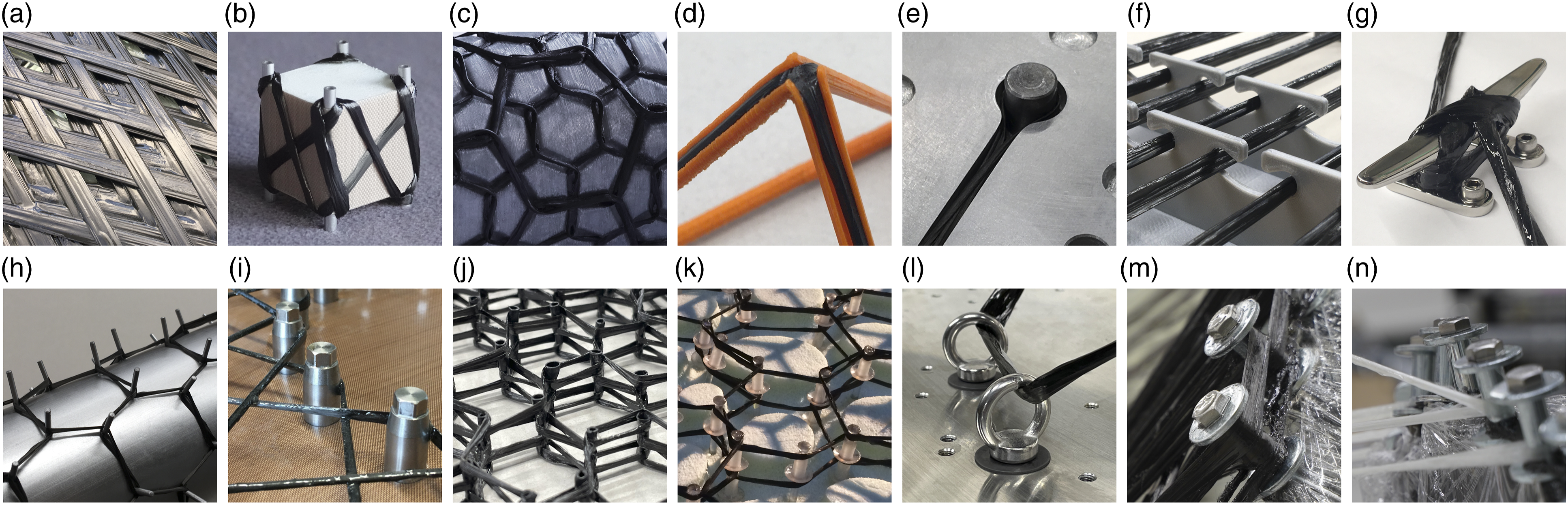
Eyelets are almost never used, as they require the fibers to be threaded through them, which is not yet feasible in terms of an automated manufacturing process. The pin category includes slender, often cylindrical, protruding and attachable elements, around which the fibers are wound using a hooking motion. Sleeve/washer combinations 16 (see Figure 1 m and n), which can be fastened with an internal bolt, are most often used in CFW. The combination with metallic fixtures makes them suitable for high fiber tensions, 40 which are typical for large components. Release agents should be applied to washers and bolts. One advantage is that the washers prevent the fibers from sliding off, thus creating a more compact fiber strand. 41 A disadvantage of the washers is that they can cut filaments during contact while hooking motions, as well as the limited number of angles possible between the fiber and pin. If this angle range is exceeded, the fibers are deposited on the perimeter of the washers and the mechanical performance decreases significantly due to the kinking 42 of the fibers. The consequence is a geometrical dependency between the pin and fiber orientation, which imposes a geometric limit on the assembly configuration. 43 Nails and spikes can be used as pins without the hold down feature. These are typically attached to wooden fixtures and used with low fiber tension for small prototypes. Another type of element is hooks, which are undercuts, pockets, or indentations within the winding fixture or the component. The fibers are in contact with the edges of those undercuts. 17 No circular hooking motion can take place and fibers can be positioned from one side only. Grooves have similar features to those of hooks. The winding fixture or component contains elongated grooves on its surface, into which fibers are placed. 44 The depth, width, and orientation correspond to the fiber material used. The winding fixture can be 3D-printed or grooves can be milled into a component. 45 The use of continuous surfaces to support fibers includes the edges and faces of the winding fixture, as well as freshly placed and already-cured fiber bundles.
Winding fixtures are defined by the way they hold the anchors in place. They can be made of metal, plastic, timber, or foam 46 by differential construction methods or milling. The criteria for the fixture selection are the cost, type of anchor, reusability of the fixture, maximum fiber tension, design freedom, and maximum curing temperature. Additional restrictions may apply if the fixture remains within the component.
Adaptive winding pin design
The developed anchor should allow fibers to be received from as many directions as possible to enable the volumetric design of CFW objects. The result of the development was an additive manufactured pin which uses a bolt connection. To be adjustable to any position within the fiber net, the complete CAD model of the winding pin was parameterized.
First iteration
The first iteration (see Figure 2) of the adaptive winding pin has a base containing a threaded hole in the bottom center. From this, a constricted pole extends upwards to a sphere. From there, several arms pultrude in different directions, which can be adjusted to match the fiber net. At the end of each arm, a disc prevents fibers from slipping off. There is a measuring tip on the outward facing surface of each disc, enabling the position and alignment of the pin can be measured before and after winding. The measuring tip is inlaid in the contour so as to not damage fibers during winding. The fibers can be placed around the pin covering the arms, sphere, and pole so that only the outer surfaces of the discs and base remain uncovered. The entire pin stays in the component. It is disadvantageous that the base limits the bolt hole depth and the central sphere reduces the pin capacity, preventing a uniform fiber placement because of surface discontinuities, which was improved in the final iteration. This iteration of the pin should be used for prototyping. First iteration of the adaptive winding pin. Top: regular configurations with 3 and 2 upwards facingarms. Bottom left: an irregular configuration with 3 arms. Bottom right: a configuration with 4 arms facing downwards.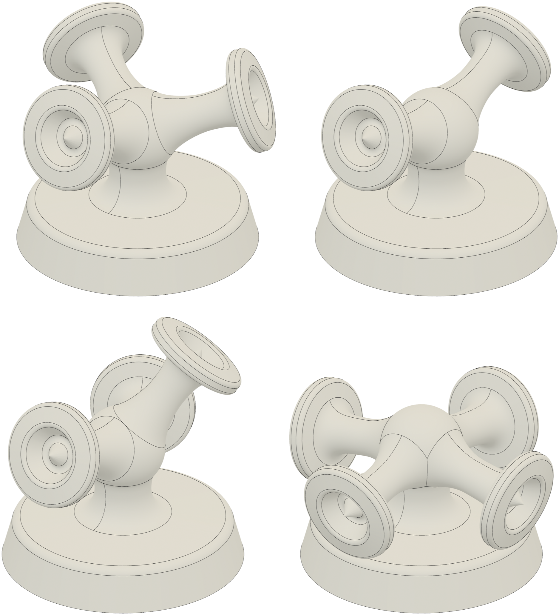
Final iteration
In the final iteration of the winding pin, the threaded hole was incorporated up to the center of the pin and the sphere was eliminated to introduce rounding with a constant curvature, see Figure 3. As a result, the screw-in depth could be increased without lengthening the pin and thus its lever arm. Almost all the surface discontinuities could be removed, which improved the fiber deposition quality.
40
Additionally, a bottom-mounted 3D-printed adapter was introduced. It could be used to clamp the pin to profiles of a modular fixture system. The reusable adapter was attached to the pin via a grub screw by the already-existing central bolt hole and removed after curing the component. The adapter includes parallel clamping surfaces to fix the pin during preprocessing and contains a slot on the bottom to align the pin with a screwdriver during assembly. The base is hexagonally shaped to make it easier to clamp the pin and align it. Final iteration of the adaptive winding pin. From left to right: several variants of the pin with 1, 2, 3, and 4 arms, including the adapter, the attachment to the profiles of the modular fixture system, and zebrastripe—analysis of a 3-arm configuration.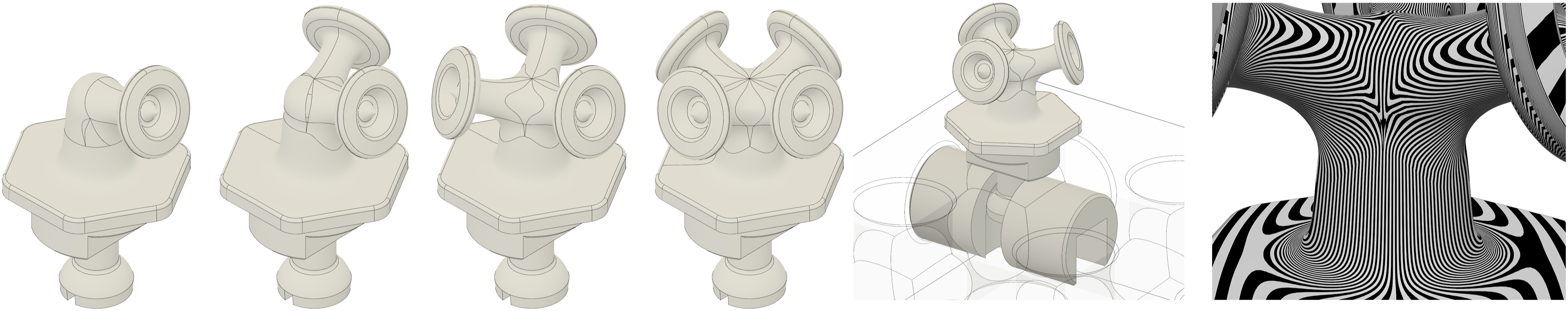
Geometric design parameters
The CAD model was driven by form-defining geometrical parameters: the height of the pin, the length of each arm, the horizontal and vertical angles of each arm, disc diameter Cross-sectional views of the final iteration of the adaptive winding pin. Top: configuration of the pin mounted to the modular fixture system. 1: base; 2: pole; 3: arm; 4: disc; 5: measuring tip; 6: grub screw; 7: adaptor; 8: planer surfaces for clamping; 9: screwdriver slot; 10: profile of the modular fixture system. Bottom: configuration of the pin after winding and assembly, parameters of the CAD model: height of the pin (blue), length of the arm (green), horizontal and vertical angles of each arm, disc diameter D_i, arm diameter d_i, base diameter D_j, pole diameter d_j, and bolt size.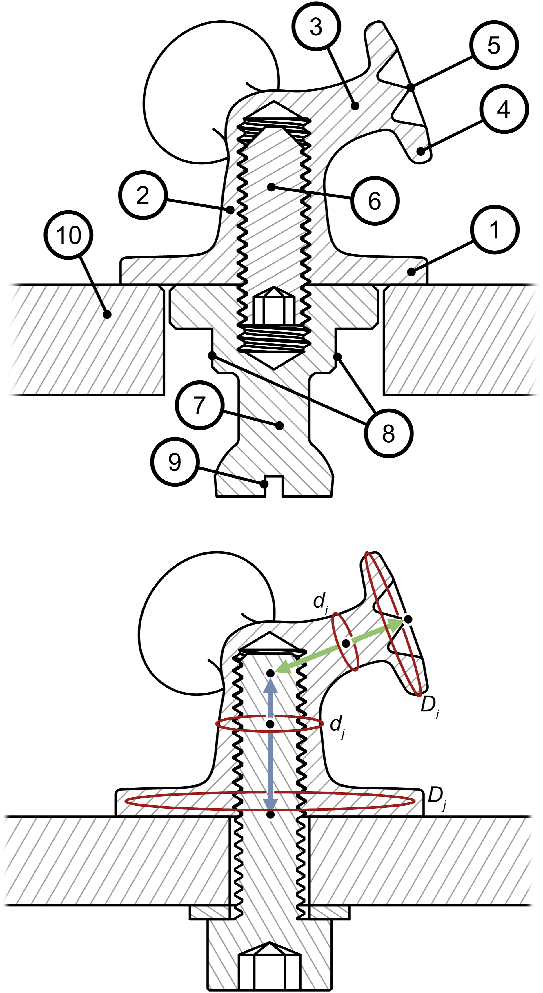
Winding technique
Compared to a sleeve/washer winding pin, the complexity of the fiber hooking increased due to the higher number of fiber placement possibilities. This allows fiber bundle alignments that are not perpendicular to the pole or arms. For example, the fiber can approach and depart the pin at the upper midpoint and hook around one of the arms from below. Fiber kinks caused by discs should be avoided by contacting the pin from orientations as far away from the discs as possible. Additionally, it is mechanically advantageous to place fiber bundles that are parallel to each other on the same side of a pin so that they are not separated. In general, the pin should be filled from the inside out and from the bottom up to minimize lever arms.
Additive manufacturing of the winding pin
The winding pin was produced by laser powder bed fusion (LPBF) using aluminum powder. An additive manufacturing process is the only feasible fabrication option because of the high geometrical complexity. Other materials such as titanium or stainless steel may be needed depending on the structural design. The use of plastics would be limited to low-performance applications. The pin surface has a high roughness set by the LPBF process parameters, see Figure 5. Therefore, relative movements between the filaments and the pin surface can damage the rovings. A smoothing post-process for all contact surfaces is not economically feasible. Sandblasting is effective but labor-intensive, whereas barrel tumbling produces unsatisfactory results on the relevant surfaces of the inner pin areas.
47
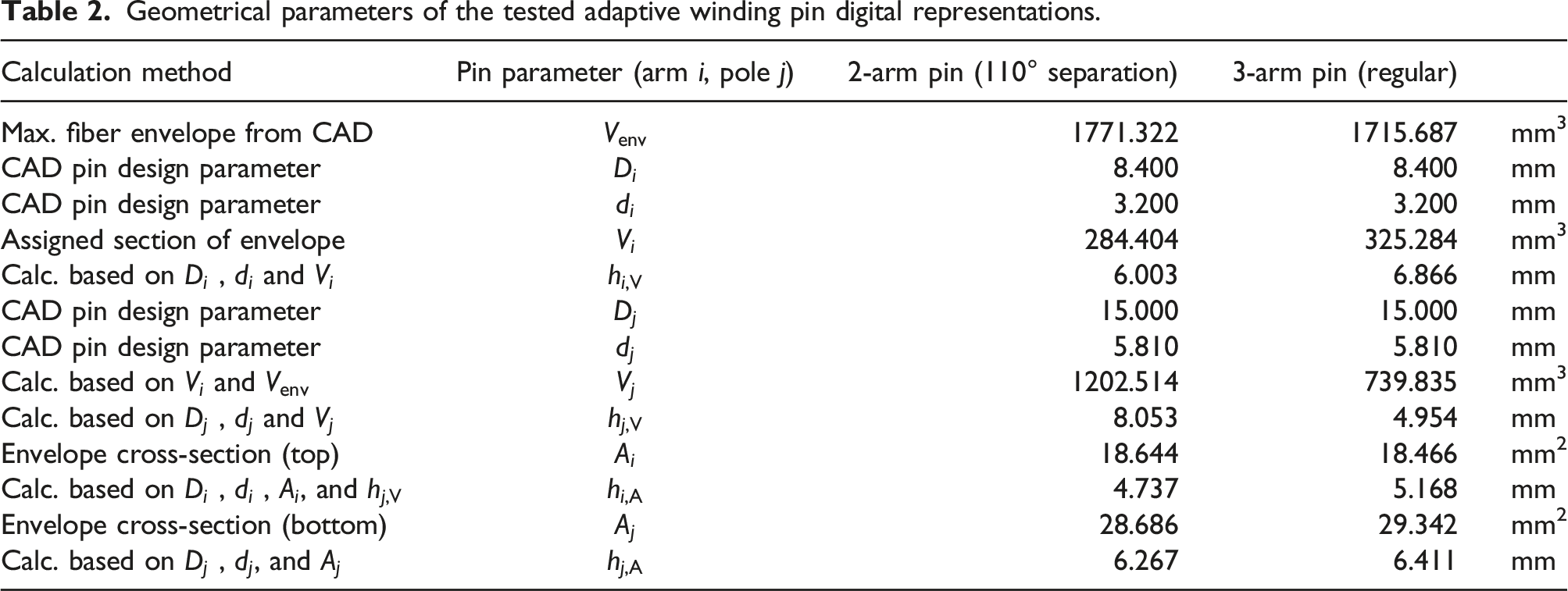
However, the use of a special winding technique48,49 can prevent fiber damage, but its implementation in robotic systems remains an open challenge due to the required complexity of the trajectories. Another potential way to mitigate minor surface irregularities would be to apply a dip coating. This would create an additional interface between the fiber composite and the pin surface, which could affect load transmission. The orientation of the pin during the printing is of decisive importance, since this determines the areas where support structures are needed to realize overhangs. Areas with support structures have more surface imperfections and should preferably not be located where fibers are mainly placed. This aspect requires quality-enhancing advancements in the LPBF process, since coatings cannot compensate for such major imperfections. Regular 3-arm adaptive winding pin made from aluminum and ready for winding. The underlaying profiles of the modular fixture system are covered by PTFE foil and the gap in between is protected by vacuum sealing tape. For the parameters of this pin, see Table 2.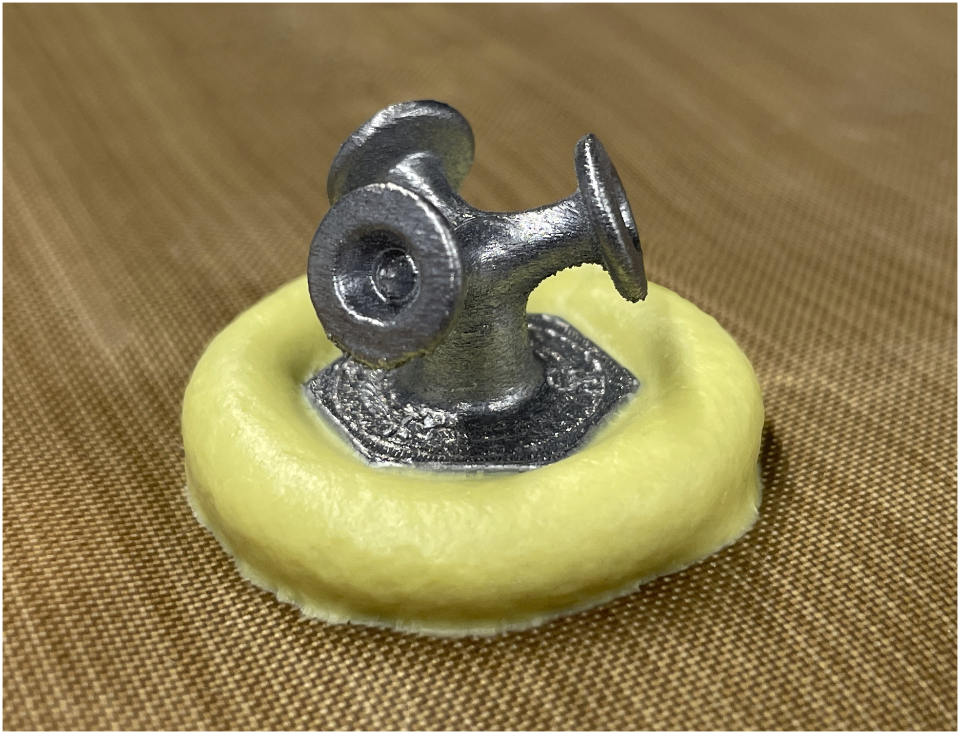
Digital representation of the winding pin
To integrate the adaptive pin into the digital design process, it is represented as multiple regular sleeve/washer winding pins, see Figure 6. The total volume Method for converting the fiber envelope of the adaptive winding pin into a sleeve/washer equivalent. From left to right: identification of the sub winding points WPS, main winding point WPM, and their orientation unit vectors; complete fiber envelope (orange); identification of the cross-sectional areas (green) and minimum volume section (blue); representation of the winding pin as separate imaginary sleeve/washer configurations.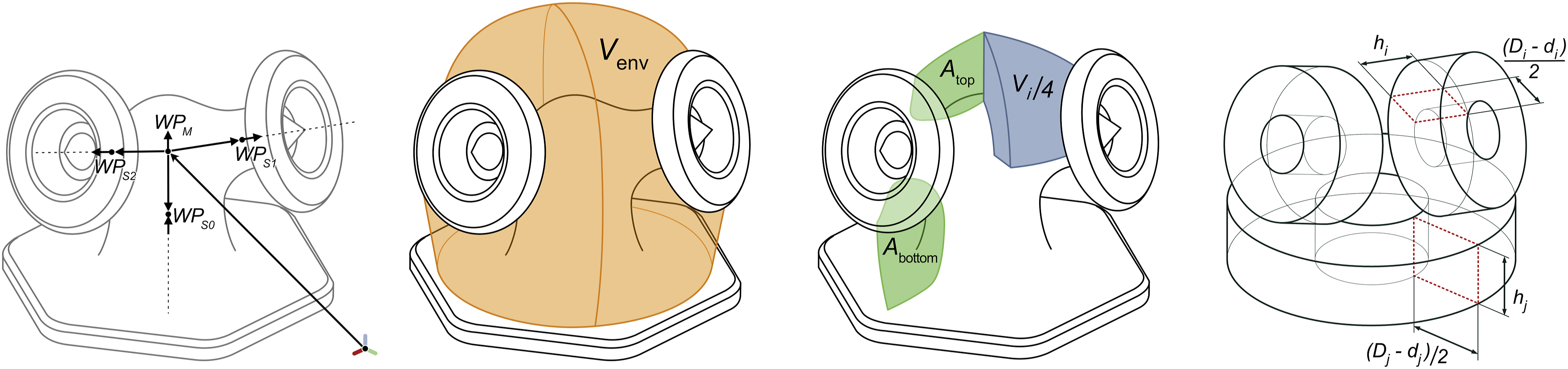
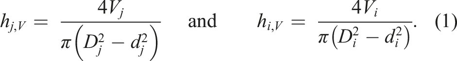
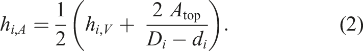
Alternatively, the sleeve/washer parameters can be calculated from the cross-sectional area of a cut of the fiber envelope in the angular orientation of each arm. In this case, the height of the imaginary sleeve of the pole can be calculated by
Winding syntax
The winding syntax 14 is a list of indicators of the winding points sorted by the chronological order in which the fiber is hooked onto the anchor of the winding point. The indicators are usually integers and refer to the winding point parameters (cartesian coordinates and orientation of the anchor). In the case of the adaptive winding pin, the winding syntax must be specified on the level of the sub winding points. The winding syntax defines the spatial arrangement of the fiber bundles between the anchors and the distances between anchors.
Hooking syntax and hooking condition
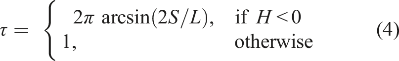
The hooking syntax of a pin describes the sequence in which fibers are hooked around it. It can be derived from the winding syntax and consists of a list of turns Exemplary visualization of different hooking conditions H.
Winding pin capacity
The pin capacity is defined as the ability of the winding pin to absorb fiber bundles. It is depleted if the next hooking would result in fibers slipping off the pin. Therefore, the same pin can have different capacities depending on the hooking syntax. The maximum volume a pin offers to absorb fibers is given as
Winding pin occupancy model
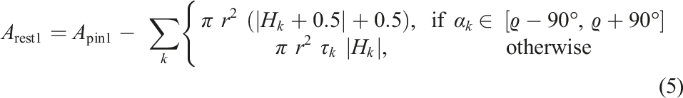
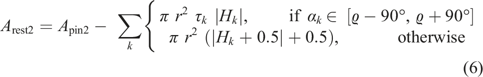
The occupancy of the pin cannot just be approximated by the ratio sum of all fiber volumes and Flowchart of the winding pin occupancy model algorithm. The procedure consists of three domains, after the parameter initialization (top domain), the filling of the pin layers with fiber volumes is approximated in an iteratively procedure (bottom left domain), followed by a stepwise reduction of the cross-sectional pin areas to obtain the occupancy (bottom right domain). The label “sum incl. tau” refers to the right side of the equations (5) and (6). Experimental testing of the occupancy algorithm for several non-trivial cases, see Table 1 and 3. Top: Sleeve/washer winding pin test case 4, the pin is completely filled as further addition of fibers would create an instable fiber accumulation. Middle: Sleeve/washer winding pin test case 5 (left pin) and case 12 (right pin), the left pin is not completely filled while the right one is, although in both cases the pin volume is not fully occupied. In the right pin fibers are about to slip over the edge of the washer at the lateral areas. Bottom: 3-arm winding pin test case 3, although only the pole and the arm in the front received fibers, the capacity of the whole pin is exhausted at this hooking step.
Since the algorithm is intended for early design phases, only a few parameters are known, such as the fiber net configuration, winding pin geometry, and fiber properties. Therefore, the algorithm relies on a model that involves several simplifications. The most important one is the neglection of compression in the fiber composite caused by fiber tension. Its implementation would require comprehensive information about the dynamic behavior of the manufacturing equipment, which is highly dependent on the component geometry and the trajectory creation methods used. The second most relevant simplification is the assumption of a constant fiber volume ratio and the absence of voids. In CFW, the fiber volume ratio varies substantially along the fiber. The void content can be significant since in CFW consolidation is primarily generated by curvature. Incorporating these aspects would require a computational model of the impregnated fiber composite material interacting with the manufacturing system. Furthermore, geometric simplifications are made with respect to fiber interactions (fiber sliding and bending, deformations of bundles, and interaction beyond the washer perimeter) that would require a physics-based soft-body simulation.
From these simplifications, the hypotheses for the developed algorithm can be derived: • The main hypothesis states that the calculation can be split into a first step, where fiber distribution is approximated based on volumes, and a second step, where the occupancy is evaluated based on hooking conditions and the pin cross-sectional area. • The second hypothesis is that the fiber volume between the washers can be mapped to quantized concentric layers and assigned to a single angular position per winding step to sufficiently approximate the fiber accumulation. • The third hypothesis states that the occupancy can be calculated by considering a single cross-sectional plane that intersects the winding pin at the angular position of the fiber distribution peak. • The fourth hypothesis states that this angular position can be found by averaging the fiber distribution, similar to a center of gravity determination by using the fiber volumes as weighting factors and the layer distance from the center as lever arm.
The fiber bundle imaginary radius can be given in mm as

If
To visualize the fiber net, the bundle diameter of each edge between two nodes (anchors) can be inserted to its corresponding position in the adjacency matrix
50
of the winding object. To implement information on the winding pin occupancy, the diameter
Results and discussion
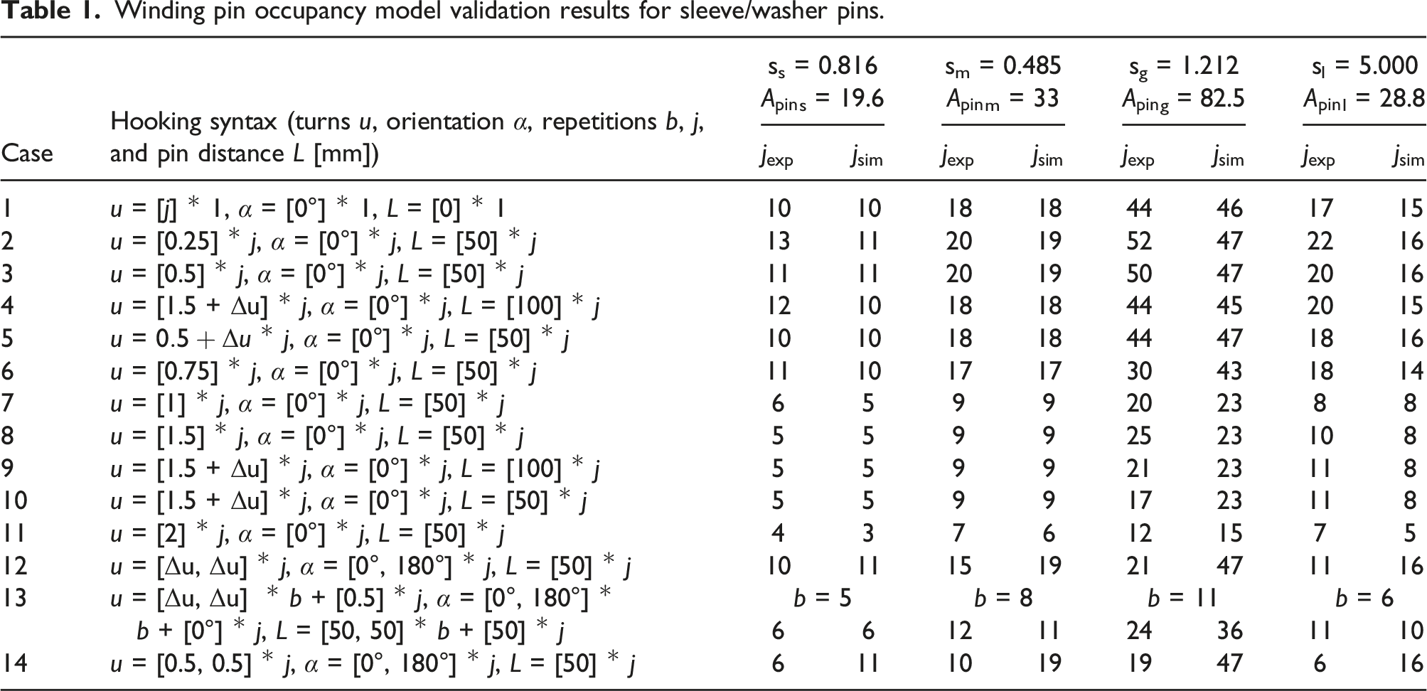
Winding pin occupancy model validation results for sleeve/washer pins.
Model validation for sleeve/washer winding pins
Sleeve/washer winding pins with different parameters (Ss = 4 mm, Ws = 8.9 mm, hs = 4 mm; Sm = 4 mm, Wm = 12.25 mm, hm = 4 mm; Sg = 4 mm, Wg = 12.25 mm, hg = 10 mm; Sl = 5 mm, Wl = 7.4 mm, and hl = 12 mm) were used, each with a slenderness
Case 1 represents the filling of the pin as conducted with a cable drum. Case 2 and 3 (
In general, the algorithm shown in the section on the winding pin occupancy model predicts the capacity of the sleeve/washer winding pins sufficiently well for the design process. For
Pin m was predicted most accurately and pin s also showed only small deviations, since for both the capacity war primarily geometrically determined. For pins with a larger
Model validation for adaptive winding pins
Geometrical parameters of the tested adaptive winding pin digital representations.
Winding pin occupancy model validation results for adaptive pins.
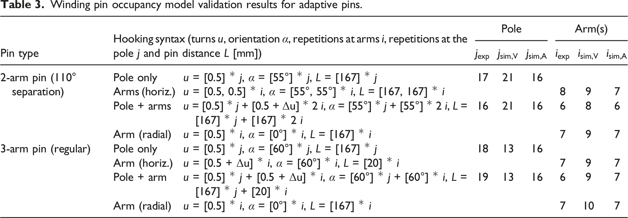
Both pins were tested in four cases. In the first one, the hooking was performed at the pole only. In the second, the fibers were spanned horizontally between the arms in such a way that they passed over the pin center, as mentioned in the section on the winding technique. For the 2-arm pin, both arms were used, whereas with the other one only one was filled. In the third case, the pole and then subsequently the arms were filled with the same hooking condition as that in case two. In the last case, only one arm was filled, with radial fibers attaching orthogonally from the arm axis.
Two methods for converting the adaptive pin geometry into a sleeve/washer equivalent were tested. For the tested hooking syntaxes, the method depending on the cross-sectional area performed better and, in contrast to the volume-based method, tended to underestimate rather than overestimate the capacity. The prediction made by the volume-based method was more accurate for the pole than for the arms. The area-based method also performed well in cases where the pole and arms were both filled. Therefore, the total fiber envelope can be divided and assessed for the sub winding points separately.
For both types of winding pins, the model performed sufficiently to be used as a design tool for CFW. Therefore, the underlying hypotheses can be considered as sufficiently confirmed in this context. The justification for this method is twofold: The calculation only relies on parameters (material and geometry) which can be easily obtained even in early design phases and the calculation time is around 100 milliseconds per pin. A highly detailed physics–based soft-body simulation of the fiber–fiber, fiber–pin, and fiber–equipment interaction potentially predicts the occupancy more precisely, but it involves the consideration of many parameters (see simplifications in the section on the winding pin occupancy model) and has to model numerous contacts between entities. Most of those parameters are unknown during the design phase.
Conclusions
The developed adaptive winding pin was deployed in laboratory-scale winding sessions to verify its design idea. The pin allows one to attach fibers from various directions without fiber kinks and removes the dependency between the pin orientation and the fiber net. By parameterizing the winding pin geometry, the individual orientation of each arm can be easily adapted to the local fiber net configuration of the pin position in the component. By using LPBF, each winding pin can be made in a unique shape at no additional costs. This is the prerequisite for each winding pin to be individually tailored to the structural requirements of the fiber net. This could lead to higher performing CFW structure in the future. The adaptive winding pin eliminates some design restrictions and allows the material to be placed only where it is needed. The multiple contact areas within a single adaptive pin facilitate a fiber placement which is more appropriate for the material due to the larger bending radius. This can help to prevent failure close to the pin, allows one to separate or merge fiber bundles, and also opens up more complex hooking syntaxes that are yet to be researched. This more homogeneous fiber arrangement could reduce variations in the structural performance. It was shown that the fiber should preferably be attached to an arm from the inside of the pin, rather than the outside. An adaptive pin is a prerequisite for voluminous, sparse, and fully stressed framework structures. However, the price of the metallic additive manufacturing limits the industrial application of the pin at large scales or in large quantities. The use of the modular fixture system in combination with the winding pin adapters helps to shorten the preparation time of the winding sessions without sacrificing geometric accuracy. The only drawback is that pin positions are mainly restricted to a grid. The winding pin capacity model can be used for relevant hooking syntaxes and typical winding pin geometries. It can also sufficiently be applied to the adaptive pin. Due to its integration in digital process planning tools, the pin capacity can be directly assessed during the early design phases, which is another step towards the realization of a fully automated CFW process chain.
Footnotes
Acknowledgments
The authors would like to express their gratitude towards their fellow researchers Erik Dieringer, Peter Hoffrogge, René Klink, Markus Merkel, Ralf Müllner and Christof Ocker. In particular, we would like to thank the Institute for Virtual Product Development at Aalen University of Applied Sciences (Zentrum für virtuelle Produktentwicklung an der Hochschule Aalen) for the additive manufacturing of the winding pins.
Author contributions
Pascal Mindermann: Conceptualization, Methodology, Software, Validation, Formal analysis, Investigation, Data Curation, Writing - Original Draft, Writing - Review and Editing, Visualization, Project administration, Funding acquisition;
Götz T. Gresser: Validation, Resources, Supervision.
Declaration of conflicting interests
The authors declared no potential conflicts of interest with respect to the research, authorship, and/or publication of this article.
Data availability statement
Data is contained within the manuscript.
Funding
The author(s) disclosed receipt of the following financial support for the research, authorship, and/or publication of this article: The authors would like to thank the Ministerium für Wissenschaft, Forschung und Kunst Baden-Württemberg (MWK; Ministry of Sciences, Research and the Arts of Baden-Wuerttemberg) for funding this research.