
Abstract
The assessment and reduction of haemolysis within mechanical circulatory support (MCS) remains a concern with regard to device safety and regulatory approval. Numerical methods for predicting haemolysis have typically been applied to rotary MCS devices and the extent to which these methods apply to positive-displacement MCS is unclear. The aim of this study was to evaluate the suitability of these methods for assessing haemolysis in positive-displacement blood pumps. Eulerian scalar-transport and Lagrangian particle-tracking approaches derived from the shear-based power-law relationship were used to calculate haemolysis in a computational fluid dynamics model of the Realheart total artificial heart. A range of power-law constants and their effect on simulated haemolysis were also investigated. Both Eulerian and Lagrangian methods identified the same key mechanism of haemolysis: leakage flow through the bileaflet valves. Whilst the magnitude of haemolysis varied with different power-law constants, the method of haemolysis generation remained consistent. The Eulerian method was more robust and reliable at identifying sites of haemolysis generation, as it was able to capture the persistent leakage flow throughout the entire pumping cycle. This study paves the way for different positive-displacement MCS devices to be compared across different operating conditions, enabling the optimisation of these pumps for improved patient outcomes.
Keywords
Introduction
Heart failure impacts approximately 64 million people globally. 1 For severe cases, a heart transplant is recommended, however the limited number of donor hearts have led to growing waiting lists. 2 Longer wait times increase the risk of transplant failure, 3 so to bridge the gap to transplant, doctors can use mechanical circulatory support (MCS) devices to assist in cardiac function.
Most MCS devices can be separated into two categories based on pumping method: rotary and positive-displacement. Rotary devices use axial or centrifugal rotation to impart energy to the fluid, generating a pressure head, whilst positive-displacement devices repeatedly displace a fixed fluid volume. Ventricular assist devices (VADs) are usually axial 4 or centrifugal5,6 though some are positive-displacement.7–10 Total artificial hearts (TAHs) are usually positive-displacement pumps,11–13 however some are rotary. 14 The Realheart TAH, developed by Scandinavian Real Heart, is a novel four-chamber positive-displacement TAH that has both atria and ventricles, and uses a displacing atrioventricular (AV) plane to produce pulsatile flow governed by a pair of bileaflet mechanical heart valves. 15
Haemolysis and thromboemboli are noted side effects of chronic MCS. Haemolysis is the damage and subsequent rupture of red blood cells, leading to the release of haemoglobin into the surrounding plasma.
16
Mechanically induced haemolysis has been shown to occur when red blood cells are exposed to elevated fluid stresses.
17
The haemolysis index
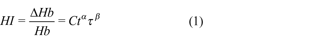
where
Various attempts have been made to model haemolysis in blood-contacting medical devices, where damage can either be calculated in an Eulerian or Lagrangian frame of reference. Garon and Farinas
26
developed an Eulerian approach, linearising the damage function (equation (1)) in time and applying it as a source term in a transport equation for the linearised index of haemolysis
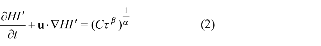
Equation (2) is solved using the velocity field and describes the haemolysis production within the entire domain. This method is commonly employed in simulating haemolysis in MCS devices, particularly rotary flow VADs. Fraser et al. 22 investigated haemolysis in various axial and centrifugal blood pumps, deriving device-specific empirical constants. Gil et al. 27 showed superior haemocompatibility in the HeartMate 3 compared to the HVAD, while Zhang et al. 28 suggested better haemocompatibility of the CH-VAD compared to the HVAD and HeartMate II under normal and hypertensive conditions. However, the Eulerian approach, as highlighted by Faghih and Sharp, 29 has several limitations, most notably that it only holds true for cases with no streamwise velocity variation, something inherent to many blood pumps. 30
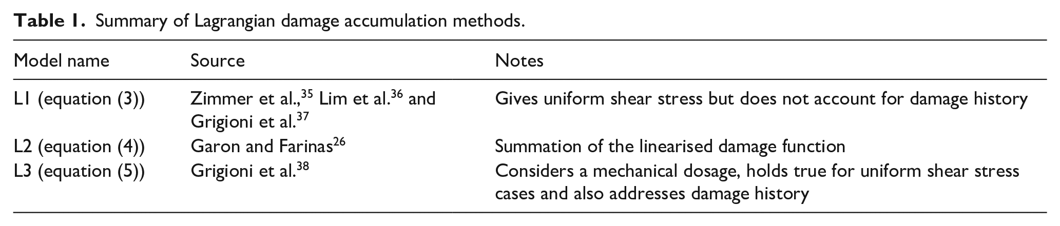
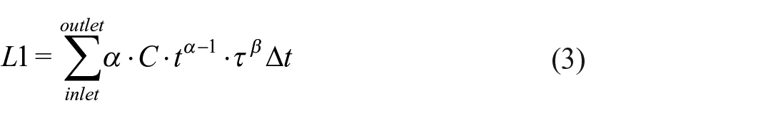
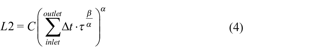
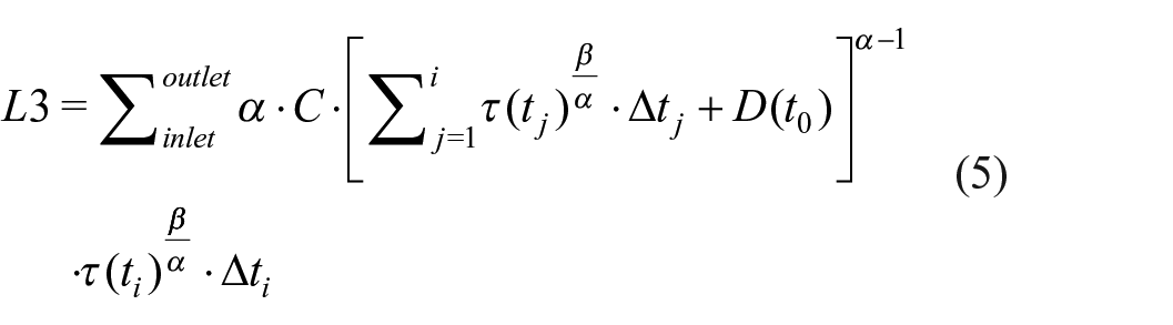
In the Lagrangian approach, damage is assessed by integrating the shear stress along particle tracks from the inlet of the device to the outlet. 31 Various damage models based on this formulation, from equations (3) to (5), are summarised in Table 1. Excluded from this list is the direct integration method by Yano et al. 32 and Song et al. 33 which has been deemed inaccurate, and the time-dependent shear loading history method by Goubergrits and Affeld, 34 found to be similar to L2. 31
Summary of Lagrangian damage accumulation methods.
where equation (5) was derived from the time derivative of a mechanical dose,
The Lagrangian method is less commonly applied to MCS, possibly due to additional post-processing requirements or the simplicity of implementing the Eulerian approach. Taskin et al. 31 compared both Eulerian and Lagrangian methods in axial shearing devices and VADs, finding neither accurately predicted the magnitude of haemolysis, though the Eulerian method could predict relative haemolysis. Wiegmann et al. 39 used a Lagrangian approach to assess rotary pump design, showing that haemolysis was negatively correlated with hydraulic efficiency.
Modelling haemolysis in positive-displacement devices is less common compared to rotary devices, with several shortcomings in the approaches that have been used. Xu et al. 40 used a Lagrangian method to analyse the effect of pusher-plate motion profiles on haemolysis in a positive-displacement VAD, but did not consider the motion and subsequent haemolysis from the bileaflet valves, a site of significant haemolytic potential.41,42 Richez et al. 43 estimated haemolysis in the Carmat TAH using average shear values during the systolic phase, neglecting the full range of shear stresses. Bierewirtz et al. 13 included an Eulerian estimation of haemolysis in the Shuttlepump TAH, although in that work the method for incorporating transient geometry and flow is not investigated.
The aim of this study was to assess the effectiveness of different shear-based haemolysis models in capturing haemolytic effects within a positive-displacement MCS device. Using a computational fluid dynamics (CFD) model of the Realheart TAH, Eulerian and Lagrangian methods were compared. Utilising different empirical constants from the literature for damage estimation, the suitability of these approaches and their applicability to positive-displacement blood pumps were assessed.
Methods
Computational domain
A CFD model of the Realheart TAH V11.2 was created using an approach similar to that used for the V11c. 44 This method used fluid-structure interactions (FSI) for the valve leaflets, enabling their movement in response to fluid forces. 45 Both V11.2 and V11c are considered legacy devices and differ slightly in shape, but both operate using the same positive-displacement principle. In the V11.2, the outflow valve has been repositioned upstream and rotated by 90°, while the atrial inflow has been centrally relocated to enhance anatomical fit (see Figure 1(a)).
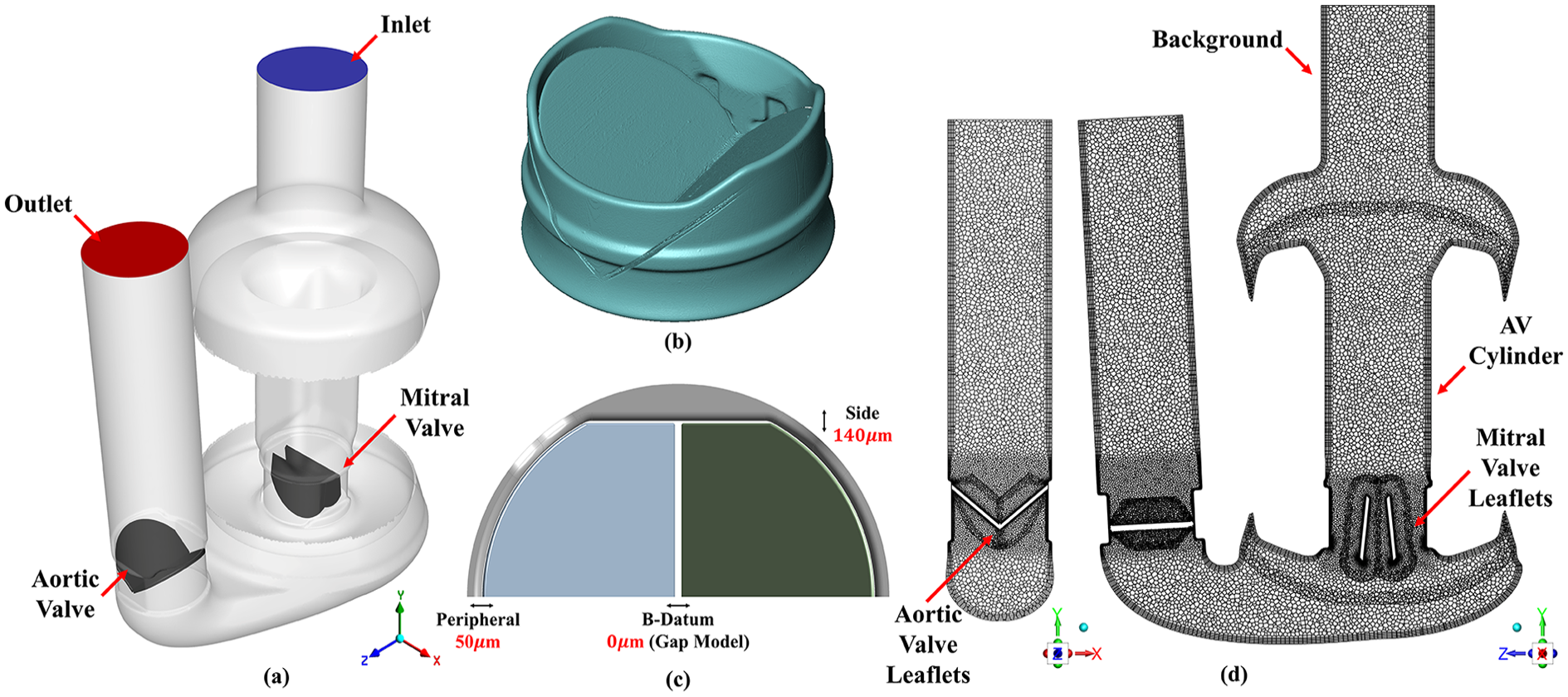
Computational domain and mesh of the Realheart V112 showing (a) location of the inlet (blue), outlet (red), mitral and aortic valves (dark grey). (b) 3D rendering from micro-CT scan of ON-X bileaflet mechanical heart valve from which valve geometry was derived. (c) Valve gap sizes implemented into the CFD model of the ON-X valve, with the gap model implemented between the leaflets approximating full closure at this location. (d) Mid-plane mesh of the CFD model, showing location of the six overset zones: background, AV cylinder, two mitral valve leaflets and two aortic valve leaflets. Left view is mid-plane mesh of the closed aortic valve, whilst right view is mid-plane of closed mitral valve. The same set of views are presented for contour plots in the results.
Valve model
A 3D model of a closed ON-X bileaflet mechanical heart valve was generated using a Nikon XT 225 micro-CT scanner (Nikon Metrology, Inc. MI, USA), shown in Figure 1(b). This enabled the size of the leaflets, housing and gaps around the edges of the leaflets to be accurately measured. The average peripheral tip gap was 50 µm and the gap near the hinge mechanism was 140 µm. These measurements were incorporated into an existing CAD model of the ON-X valve using Ansys DesignModeler V2022R2 (Ansys Inc. PA, USA), as shown in Figure 1(c). This model excluded the hinge geometry, instead using a constant 140 µm side gap and limiting the leaflets to rotate between 0° (fully closed) and 44° (fully open) around a single axis. 44 Micro-CT post-processing was achieved using Avizo 9.0 (Thermo Fisher Scientific, MA, USA).
Meshing
An overset meshing approach was used to combine the moving components into a single continuous mesh which contained a background zone, a translating AV cylinder zone, two mesh zones for the translating and rotating mitral valve leaflets and two mesh zones for the rotating aortic valve leaflets (Figure 1(d)). Ansys Fluent Meshing V2022 R2 (Ansys Inc. PA, USA) was used to mesh each individual overset zone before later combining to form the full device.
Regurgitant leakage flow through a closed mechanical heart valve has been shown to play a major role in the haemolytic potential of MCS devices.46–49 Therefore, to create the appropriate mesh for the full device, a mesh sensitivity study was conducted in which a pressure gradient was applied to a static closed valve within a fluid cylinder, inducing leakage flow. Four meshes were created by reducing both global and local mesh sizing around the valve leaflets. Between the two leaflets, where no gap existed and both leaflets touched, the gap model function, as previously used in the V11c model, 44 was applied to approximate a perfect seal. Bulk flow mesh parameters for the rest of the pump were the same from the validated model of v11c in our previous study. 44 The most suitable mesh, resulting in a total of 5.1 million elements, was chosen for the full device. Further details on the mesh sensitivity study are available in the Supplemental Material.
Haemolysis models
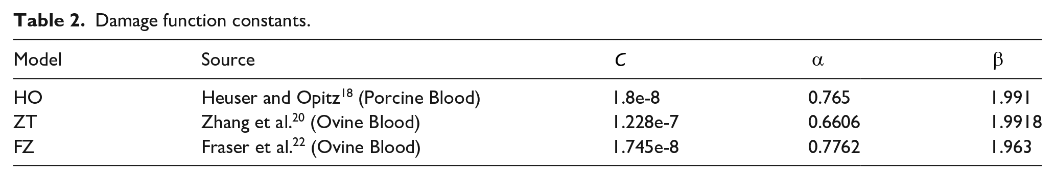
Haemolysis was solved using Lagrangian and Eulerian approaches. For both model types, three sets of empirically derived damage function constants,
noting that
Damage function constants.
In the Eulerian approach, the transient form of the passive scalar transport model was solved, as shown in equation (2), to calculate
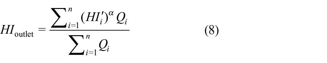
where
For the Lagrangian approach, 100 particles were seeded at a random location on the inlet face at every time step during the second cycle, totalling approximately 26,000 particles. After the second cycle, the injection was disabled and the particles were tracked until leaving the domain through either the inlet or outlet.
The three Lagrangian formulations outlined in equations (3–5) were then calculated for each of the empirical constants shown in Table 2 for only those particles that exited the domain through the outlet. Particle post-processing was performed using MATLAB 2022b (Mathworks, MA, USA).
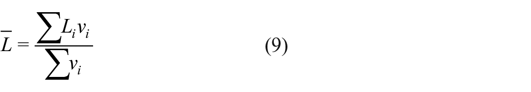
To calculate an average Lagrangian haemolysis from all the particles,
Collectively, three Eulerian and nine Lagrangian values of
Boundary conditions
A constant pressure of 10 mmHg was assigned at the inlet. At the outlet, a two-element Windkessel model was applied to approximate downstream compliance,
Numerical procedure
Ansys Fluent V2022 R2 (Ansys Inc. PA, USA) was used to solve: the Unsteady Reynolds Averaged Navier Stokes equations, with a
Second-order upwind discretisation schemes were used for all equations utilising a least-squares gradient method. High resolution tracking was used for the particles with a maximum number of steps of 5000 and a step length factor of 5.
Heart rate and stroke length were set to 105 bpm and 23.7 mm, respectively, based on unpublished in vitro estimates for producing a cardiac output of approximately 5 L/min.
The model was solved on a Microsoft Azure cloud HPC system operated by the University of Bath,
50
using 120 AMD EPYC 7V73X (Milan-X) CPU cores, taking approximately 40,000 core hours to complete. Cyclic convergence was assessed by calculating the relative error between cyclic averages of
Results
Flow field
Figure 2 shows the key flow field results from the last (ninth) cycle. Average flow rate was 4.95 L/min, peaking at 18 L/min at mid systole. Mean pressure head was 107 mmHg, with a pulse pressure of 45 mmHg and a peak of 140 mmHg shortly before end systole. Leakage flow, driven by pressure gradients across the valves, was observed during systole (around the mitral valve) and diastole (around the aortic valve). During diastole the mean aortic leakage flow rate was 0.5 L/min, accumulating 3 mL of leakage volume per cycle. Peak leakage velocity was in the side gaps, with an approximate magnitude of 4.75 and 3.75 m/s during systole (mitral valve) and diastole (aortic valve) respectively. Peak leakage flow through the peripheral tip was 1.5 and 1.1 m/s during systole and diastole respectively. Leakage flow during systole correlated with increasing pressure gradients and mitral valve translation velocity, peaking around mid-systole, while pressure gradients peaked just before end-systole. The ninth cycle velocity and pressure contours can be seen in Supplemental Videos S1 and S2.
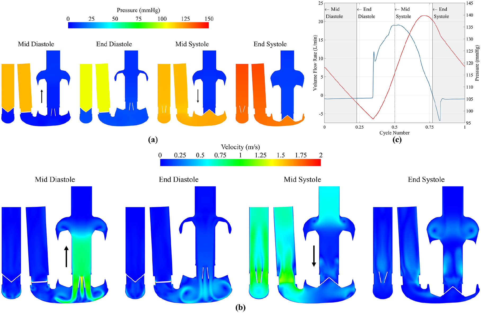
(a) Pressure and (b) velocity flow field contour plots at mid diastole, end diastole, mid systole and end systole. Pressure contours are clipped between 0 and 150 Pa. Velocity contours clipped between 0 and 2 m/s. Black arrows indicate direction of AV plane motion, downwards during systole and upwards during diastole. (c) Volume flow rate and pressure at the outlet, showing the time points equating to mid diastole, end diastole, mid systole and end systole.
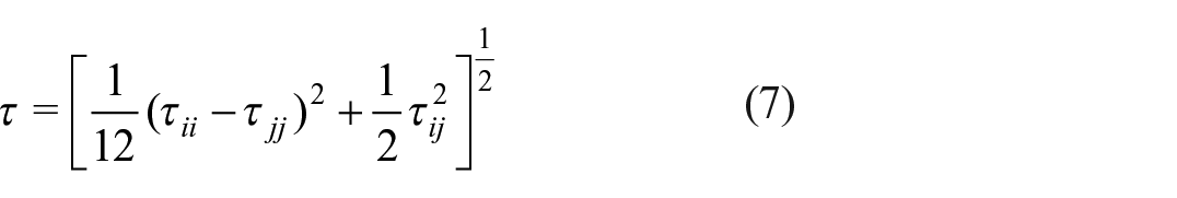
Shear stress
Figure 3(a) shows the volume-averaged scalar shear stress, with peaks labelled 1–4 corresponding to key events in the cardiac cycle. At these times, the volumetric distribution of shear stress was investigated and presented in Figure 3(b) alongside the time-averaged mean value. Higher stresses were present at valve openings (2 and 4), but over a small volume of fluid. About 99% of the volume was below 3.9, 2.9, 3.5 and 2.9 Pa for points 1–4 respectively, and 3.1 Pa for the mean value.
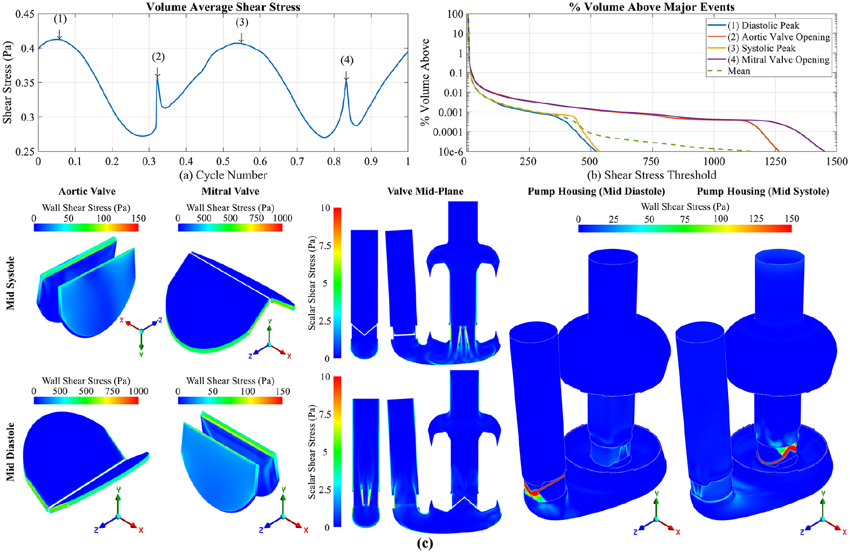
(a) Volume average shear stress over one cycle with time points 1: mid diastole, 2: aortic valve, opening 3: mid systole, 4: mitral valve opening. (b) Percentage volume above a threshold shear stress for the four defined time points, including the mean percentage volume above a threshold shear in green. (c) Wall shear stress on the valve leaflets and pump housing, and scalar shear stress on the mid-plane of the valves at mid systole and mid diastole. Closed valves are clipped to between 0 and 1000 Pa, whilst open valves and pump housing are between 0 and 150 Pa. Scalar shear stress clipped to 0 and 10 Pa. Note the aortic valve at mid systole is viewed upside down.
Figure 3(c) shows wall shear stress on the valve leaflets and pump housing at time points 1 and 3, as well as the scalar shear stress in the bulk flow. The highest wall shear on the valves occurs in the side gaps (140 µm width) of both aortic and mitral valves, peaking at 530 Pa during diastole (aortic valve) and 540 Pa during systole (mitral valve). Shear in the peripheral tip gaps (50 µm width) were lower, with values of 430 Pa during diastole (aortic) and 440 Pa during systole (mitral). The highest stresses observed on the pump housing was around the closed valve leaflets as expected, with some elevated wall shear, approximately 30–50 Pa, in the housing around the open valve at points 1 and 3. Scalar shear stress in the bulk flow was elevated downstream of the open valves at each time point where the three-jet structure was present, with approximate values between 5 and 7 Pa.
For the open valves, the highest shear was on the leading edge of the leaflets: flow in the
Eulerian haemolysis
In Figure 4(a),
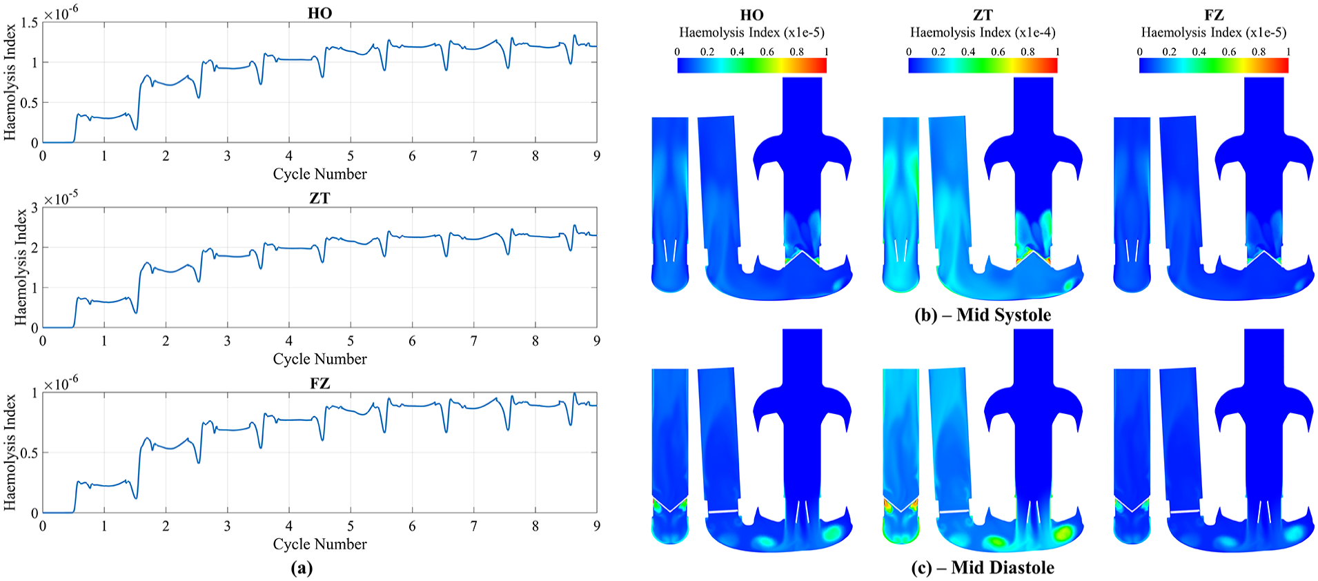
(a) Transient Eulerian mass-weighted haemolysis index results for HO, ZT and FZ constants at the outlet. Contour plots of the Eulerian haemolysis index at (b) mid systole and (c) mid diastole for HO, ZT and FZ constants. Note that HO and FZ are clipped between 0 and 1e-5, whilst ZT is clipped between 0 and 1e-4.
The
Lagrangian haemolysis
Of the total 25,800 particles that were injected, 12,172 (47.2%) escaped through the inlet, 11,027 (42.7%) escaped through the outlet and 2,601 (10.1%) remained after nine cycles, predominately in the ventricle and outflow. Only particles that travelled from the inlet to the outlet were considered for further analysis. The paths that particles took can be seen in Supplemental Video S4. Additional information regarding convergence of haemolysis results with regards to number of particles and particle time step can be found in the Supplemental Materials.
Figure 5 a plots the final
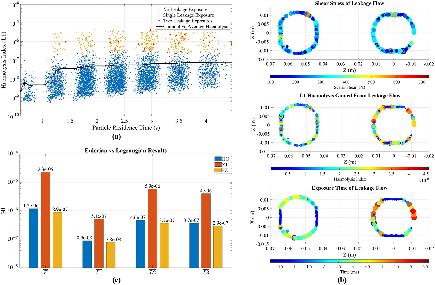
(a) Particle residence time against Haemolysis index using L1 formulation and FZ constants, showing no leakage exposure (blue), single leakage exposure (yellow) and two leakage exposures (red). (b) Shear stress, approximate exposure time and haemolysis index gained from leakage flow events. (c) Comparison of last cycle mean Eulerian haemolysis index and mean Lagrangian formulations for HO, ZT and FZ constants. Note the HI scale is logarithmic.
As residence time increased,
Figure 5(b) displays the shear stress, exposure time and resulting accumulation of haemolysis for particles experiencing leakage flow. There was relatively consistent exposure around the edges of the aortic valve during diastole (203 Pa ± 87 Pa) and mitral valve during systole (214 Pa ± 99 Pa). Exposure time was calculated using particle velocity and gap distance of 0.85 mm, the thickness of the leaflet when closed. Results aligned with observations of the velocity field in Figure 2(b), indicating side leakage flow had higher velocity, resulting in 4–5× smaller exposure times compared to the peripheral tip gap. Results show that the mitral valve was slightly more haemolytic
Figure 5(c) presents
Regarding the remaining particles within the domain, the majority were located in the ventricle and outflow. Using FZ constants and the
Discussion
In this study, one Eulerian and three Lagrangian approaches to simulating haemolysis were used in conjunction with three sets of empirical damage function constants from the literature to assess haemolysis generation in a positive-displacement TAH using a CFD and FSI approach.
Most haemolysis simulations focus on continuous flow rotary blood pumps which have statistically steady temporal behaviour, although the instantaneous flow field is unsteady. This allows for steady-state assumptions which enables the simulation of haemolysis as a post-processing step. However, positive-displacement pumps produce inherently unsteady pulsatile flow, thus requiring a transient simulation and complicating the post-processing step of estimating haemolysis. In this study, Eulerian and Lagrangian haemolysis was simulated at the same time as the flow field, yielding results that asymptotically tended toward comparable single-pass cycle-steady solutions that could be compared with experimental measurements of the modified index of haemolysis:
Gao et al.
51
used the same approaches as Taskin et al.
31
to simulate haemolysis in a roller pump. Both studies showed the same order for the Lagrangian methods that was found in this study
The variation in haemolysis with choice of empirical constants broadly followed the differences in the constants themselves. ZT’s
Bludszuweit’s equivalent scalar shear stress combined the nine components of the stress tensor into a scalar for the haemolysis source term. 52 This scalar shear stress was hypothesised to correlate with membrane failure in red blood cells, making it a suitable choice for using in haemolysis simulations. 53 There are several other equivalent stress formulations in use, such as the von Mises, which is based on the second invariant of the viscous stress tensor, or the Tresca criterion, which considers maximum stresses.54,55 Yu et al. 55 investigated haemolysis using various equivalent stress formulations, and showed that the choice of empirical damage constants had a much greater impact on solution outcome than choice of equivalent stress, a result echoed by others. 56 Additionally, whilst this study employed a turbulent approach, turbulent stresses were not considered due to the uncertainty surrounding their impact on the solution.57,58
Another explanation for Eulerian and Lagrangian differences may come from how they captured the key haemolysis mechanism: leakage flow past closed valve leaflets. Micro-CT scans of the ON-X valve showed no b-datum gap, with 140 µm hinge side gaps and 50 µm peripheral tip gaps. This resulted in sustained larger leakage jets around the hinge region, noting that this region was not explicitly modelled, and smaller jets on the periphery. Manning et al. 59 observed similar behaviour in vitro, supporting this modelling approach. Leakage flow was persistent throughout the cycle, generating haemolysis consistently in the Eulerian approach. However, the Lagrangian approach indicated that while leakage flow contributed most to haemolysis, high shear exposure occurred only for a few particles, resulting in discontinuous exposure events. The remaining particles after nine cycles were shown to be more haemolytic than the current average of escaped particles. They would ultimately become more haemolysed as they traversed the rest of the pump towards the outlet. However, since the majority were in the ventricle or the outflow further haemolysis would be small. Convergence with regards to the number of seeded particles was observed, as shown in the Supplemental Materials, indicating that seeding additional particles would not significantly change the calculated haemolysis value.
Despite differences between the two approaches, Taskin et al.
31
highlighted the ability to effectively calculate relative differences in haemolysis in different fluid-flow environments and operating condition using the shear-based Eulerian method, albeit with significant error compared to experimental values. These errors originate from the simplification of the mechanical and biological processes involved in haemolysis that are required to compute it in a simplified way.
16
Improvements to the capture of these mechanisms, such as strain-based or explicit cell modelling, will ultimately lead to more accurate haemolysis predictions, but at greater complexity and computational cost. The empirical constants in this study were chosen for their extensive use in the literature and the possibility of comparison to other blood pumps. Taking the Eulerian results with FZ constants, and comparing this study to Fraser et al.,
22
the Realheart TAH potentially generates lower relative haemolysis than the four simulated VADs from that study (approximately
Finally, the Eulerian method is better suited to visualising and understanding the underlying mechanisms of haemolysis generation and ways of optimising the design of the device. When particles are post-processed to understand their shear stress history, the results are viewed in an Eulerian frame anyway (Figure 5(b)). It is uncertain whether a particle, or enough particles, will experience the primary mechanisms for haemolysis, making optimisations of the pump challenging. Thus, the Eulerian method can be the preferred approach for tackling optimisation.
Limitations
Particles were generally exposed to leakage flow shear stress during the middle of systole and diastole when the time step was at its largest. As particle shear stress data was sampled at the same time as the flow field, there may have been insufficient temporal accuracy to capture the short leakage flow exposure of a particle. To overcome this, smaller solution time steps, or local time-stepping for each particle could be used in future studies, but at an increased computational cost. Additionally, micro-CT capture of the valve was not under pressurised conditions, possibly leading to an overestimation of leaflet gap size and subsequent amount of leakage flow. This could be rectified in future studies by imaging the valve under pressure.
Conclusion
In conclusion, a transient CFD model, utilising a previously validated FSI valve motion methodology, was employed to evaluate shear-based haemolysis models in the Realheart TAH V112. The study used Eulerian and Lagrangian methods with different empirical damage constants, finding that both methods captured the primary driver of haemolysis: leakage flow around closed valve leaflets, and that the choice of constants did not impact this capture. However, the Eulerian method, with ease of implementation and improved visualisation of damage, was more suitable for modelling haemolysis in this application. Future research will focus on validating simulated results against experiments and exploring haemolysis variations with operating conditions and device design changes.
Supplemental Material
sj-docx-1-jao-10.1177_03913988241267797 – Supplemental material for Assessment of haemolysis models for a positive-displacement total artificial heart
Supplemental material, sj-docx-1-jao-10.1177_03913988241267797 for Assessment of haemolysis models for a positive-displacement total artificial heart by Joseph Bornoff, Shaikh Faisal Zaman, Azad Najar, Thomas Finocchiaro, Ina Laura Perkins, Andrew N Cookson and Katharine H Fraser in The International Journal of Artificial Organs
Supplemental Material
sj-pdf-2-jao-10.1177_03913988241267797 – Supplemental material for Assessment of haemolysis models for a positive-displacement total artificial heart
Supplemental material, sj-pdf-2-jao-10.1177_03913988241267797 for Assessment of haemolysis models for a positive-displacement total artificial heart by Joseph Bornoff, Shaikh Faisal Zaman, Azad Najar, Thomas Finocchiaro, Ina Laura Perkins, Andrew N Cookson and Katharine H Fraser in The International Journal of Artificial Organs
Supplemental Material
sj-pdf-3-jao-10.1177_03913988241267797 – Supplemental material for Assessment of haemolysis models for a positive-displacement total artificial heart
Supplemental material, sj-pdf-3-jao-10.1177_03913988241267797 for Assessment of haemolysis models for a positive-displacement total artificial heart by Joseph Bornoff, Shaikh Faisal Zaman, Azad Najar, Thomas Finocchiaro, Ina Laura Perkins, Andrew N Cookson and Katharine H Fraser in The International Journal of Artificial Organs
Footnotes
Acknowledgements
The authors gratefully acknowledge the University of Bath’s Research Computing Group (doi.org/10.15125/b6cd-s854) for their support in this work.
Declaration of conflicting interests
The author(s) declared the following potential conflicts of interest with respect to the research, authorship, and/or publication of this article: S.F.Z, A.N., T.F. and I.L.P. are employees of or consultants to and/or shareholders of Scandinavian Real Heart AB. J.B., A.N.C. and K.H.F. declare no potential conflicts of interest.
Funding
The author(s) disclosed receipt of the following financial support for the research, authorship, and/or publication of this article: J.B. PhD funded 50/50 from Scandinavian Real Heart AB and EPSRC (Reference: 2426107).
Supplemental material
Supplemental material for this article is available online.
References
Supplementary Material
Please find the following supplemental material available below.
For Open Access articles published under a Creative Commons License, all supplemental material carries the same license as the article it is associated with.
For non-Open Access articles published, all supplemental material carries a non-exclusive license, and permission requests for re-use of supplemental material or any part of supplemental material shall be sent directly to the copyright owner as specified in the copyright notice associated with the article.