
Abstract
The transverse joint sealant for a jointed plain concrete pavement (JPCP) minimizes the entry of moisture, deicing salts, and incompressibles. This reduces the potential for the development of durability issues, erosion, pumping, faulting, spalling, and blow-ups. Sealant performance is influenced by sealant material, joint reservoir design, and the timing and quality of the installation. A laboratory study was performed to evaluate three joint design/material combinations subjected to simulated joint opening/closing and vehicle load fatigue that would occur in a 15 ft JPCP throughout a 42-year service life and freeze-thaw cycles. Data collected from an instrumented pavement was used to establish the loading conditions throughout the 42 years. Extensibility testing was performed on newly sealed joints as well as sealed joints with the simulated service life loadings to assess the performance. The adhesive strength for the asphalt sealed joints (26 pounds per square inch [psi]) was found to be statistically significantly higher than the silicone sealed joints (22 psi). Additionally, it was observed that asphalt filled joints exhibited substantial cohesive failures because of the narrow joint width and the difficulty in adequately filling the joint. From these results, it was concluded that silicone and asphalt sealant material and reservoir designs are sufficient to achieve long-term performance for 15 ft JPCPs for the JPCP design and environmental conditions considered, while asphalt filled joints are recommended for shorter slabs. These results assume that all joints are activated before sealing to prevent over- and under-filling of the joints, which can lead to premature sealant failure.
Introduction
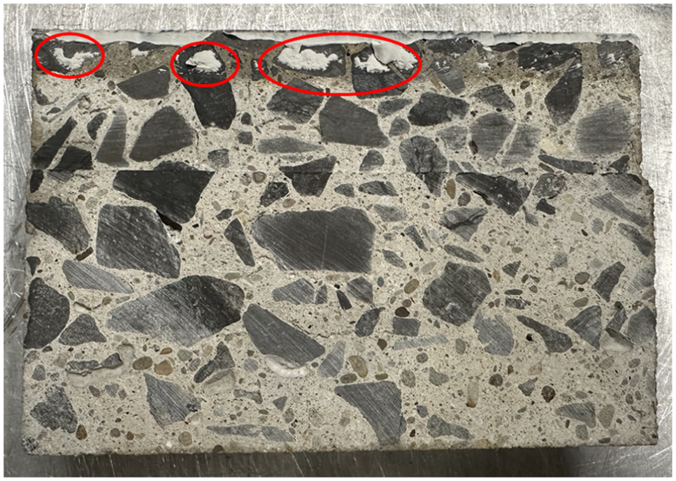
Transverse joints in jointed plain concrete pavements (JPCPs) are sawed to control cracking caused by temperature fluctuations. These joints are typically sealed or filled to minimize the infiltration of moisture and incompressibles into the joint. Infiltration of moisture can lead to erosion of the base layer and pumping, which can cause faulting and corner breaks. Some state departments of transportation (DOTs) specify the use of drainable bases and edge drains to facilitate movement of moisture from beneath the pavement that infiltrates through the unsealed or poorly sealed joints and pavement surface defects. Good sealant performance is still imperative, as the sealant also must also prevent incompressibles (sand, small stones, pebbles, etc.) from becoming lodged in the joint (Figure 1). A build-up of incompressibles in the joint can restrict joint closure during warmer temperatures resulting in spalling and potentially blowups ( 1 ). For these reasons, good joint sealant performance is imperative for mitigating pavement distresses and achieving the desired design life.
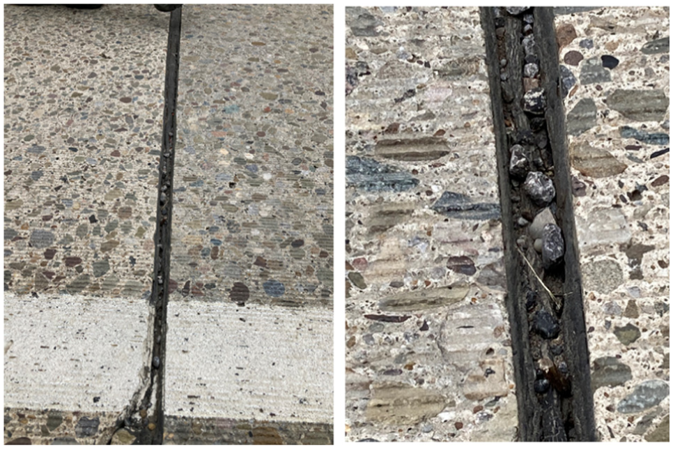
Wide joint with cohesive joint sealant failure and incompressibles, full view (left) and enlarged view (right) (SR-66, near Ford City, PA).
The main failure mechanisms for sealants are adhesive failures and cohesive failures.
Adhesive failure is caused by a loss of bond between the sealant material and the concrete reservoir walls. Proper adhesion of the sealant to the concrete is a function of bond strength, cleanliness of the bond surface, and depth of the sealant. Sealant bond strength requirements are specified in ASTM D5329 for hot-applied sealants and ASTM D412 for thermoplastic elastomers ( 2 , 3 ). These requirements must be satisfied for joint sealants used in concrete pavement construction. It has been noted by FHWA that some dolomitic limestone aggregates (e.g., river gravel) are more sensitive to silicone sealants than other aggregates ( 4 ). This can lead to decreased bond strength and a greater likelihood of adhesive failure. A chemically compatible sealant should be selected based on the aggregate type used in the concrete substrate to decrease the likelihood of a premature adhesive failure.
The cleanliness of the bond surface is also important for preventing adhesive failure. Bond surface cleanliness is dependent on the level of care taken to prepare the surface. Standard practice for joint preparation before sealing consists of power washing, media blasting and air-blowing the joint, and a final visual inspection ( 5 ). Slurry residue from saw cutting, debris, or excess moisture may be left inside the joint if proper care is not taken for each of these steps, making it more difficult for the sealant to bond to the concrete. Additionally, it is important that the sealant depth is sufficiently large to prevent premature adhesive failure. The depth of the sealant is specified through the shape factor, which is the ratio of the sealant width to depth (W:D). A smaller shape factor (larger sealant depth) will provide more bond area for the sealant, allowing bond stresses to dissipate over a larger surface. A sufficiently large sealant depth should be chosen—such that the bond stresses are less than the bond strength during joint opening—to decrease the likelihood of a premature adhesive failure.
Cohesive failure is exhibited by tearing within the sealant material caused by high tensile strains. During the winter months, drops in temperature cause the concrete pavement slab to contract and the joints to open. This induces strain into the sealant, with larger drops in temperature resulting in larger tensile strains and the possibility of premature cohesive failure. The likelihood of a cohesive failure will depend on the sealant properties (allowable strain) as well as the amount that the joint will open in the coldest month (a function of the slab length, concrete coefficient of thermal expansion (CTE), drying shrinkage, and the lowest pavement temperature). Sealant tensile properties are specified in ASTM D5329 for hot-applied sealants and ASTM D412 for thermoplastic elastomers ( 2 , 3 ). The allowable strain of a sealant is dependent on the type of sealant used, typically specified as 25% for asphalt sealants and 50% for silicone sealants. The maximum strain that develops at the time the joint opens must be less than the allowable strain, to prevent premature cohesive failures. This can be achieved by ensuring the sealant width is sufficiently large to reduce the strains for pavements with larger joint openings.
Proper construction, joint design, and sealant material selection are needed to prevent premature adhesive and cohesive failures and to mitigate the infiltration of moisture and incompressibles. Typical construction practices are specified in DOT construction manuals, which include joint sawing, cleaning, and sealing/filling procedures. Poor construction quality can play a significant role in premature joint failure. However, the scope of this study is limited to design and material selection to isolate the effects of poor construction quality from premature joint sealant failure. Joint reservoir design is conducted using prediction equations for estimating the maximum joint opening, which corresponds to the maximum strain. A sufficient sealant depth and width must be selected using this design process to limit the adhesive and cohesive stresses generated during joint opening. Material specifications, such as ASTM standards D5329 and D412, are used by state DOTs to ensure sealants meet adhesive and cohesive requirements for pavement construction ( 2 , 3 ). Despite this, premature adhesive and cohesive failures are still being reported by state DOTs ( 6 ). This could be because current design and material selection processes do not account for accumulated damage to the sealant resulting from fatigue loading representative of in situ conditions.
Some research has focused on evaluating the joint opening prediction equations used, along with the allowable strain and shape factor, to design the reservoir more effectively ( 7 ). Additionally, modified versions of the standard adhesion and cohesion tests have incorporated aging, sealant thickness, and moisture effects, but often neglect critical field conditions such as freeze-thaw cycles and fatigue loading ( 8 – 10 ). While some studies have attempted to include fatigue effects, many use unrealistic loading cycles or non-representative joint configurations ( 11 – 14 ). Therefore, there is a need to assess the performance of standard joint reservoir and sealant designs that have undergone fatigue conditions representative of the sealants of in situ pavements. The purpose of this laboratory study is to assess and quantify the performance of standard joint designs and sealant materials under typical long-term field loading conditions for Pennsylvania, U.S. The performance of varying joint reservoir geometries and sealant materials was assessed for newly sealed joints, as well as joints that had been subjected to long-term fatigue.
Methodology
Three joint sealant designs (Figure 2) were investigated: 1) asphalt sealed reservoir, 2) asphalt filled, and 3) silicone sealed reservoir. The asphalt sealant used was a Type IV material meeting the requirements of ASTM D6690 ( 15 ). The asphalt reservoir design followed Pennsylvania DOT (PennDOT) Detail D (Publication 72M), with a 0.375 in. width and 0.75 in. depth, yielding a shape factor (W:D) of 1:2 ( 16 ). The asphalt filled design followed American Concrete Paving Association recommendations, with a 0.25 in. width and 2.375 in. depth, resulting in a shape factor of 1:9.5 ( 17 ). The silicone sealant was a non-sag formulation with a tensile strength of 175 pounds per square inch (psi), as per ASTM D412, 35 psi at 100% elongation, and an elongation at break of approximately 1,000% ( 18 ). The silicone reservoir design followed PennDOT Type P (Publication 72M), with both width and depth of 0.375 in., giving a 1:1 shape factor ( 16 ).
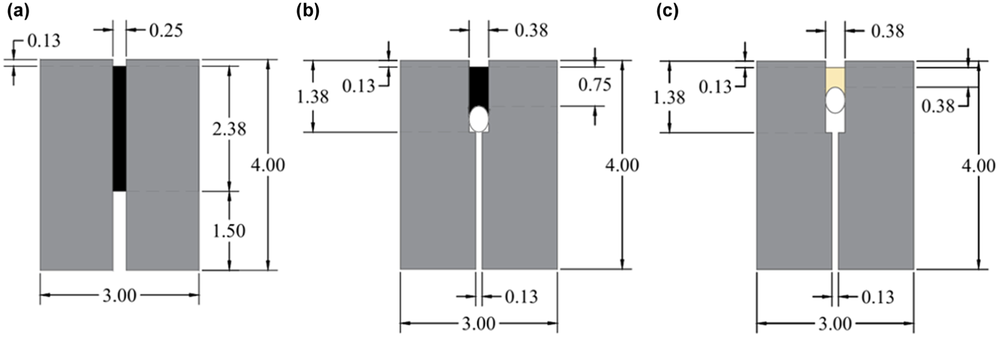
Cross-sectional dimensions of the specimens tested: (a) asphalt filled design, (b) asphalt reservoir, and (c) silicone reservoir design.
Specimen Fabrication
Custom forms were constructed to mold 3 x 4 x 6 in. specimens. The forms included 0.125 in. thick plastic spacers extending 1 in. outward from the bottom of the form to simulate a portion of an initial saw cut that would be constructed in the field and serve as a sawing reference. Four binding posts (two per face) were embedded in each mold (Figure 3) to facilitate mounting in the fatigue loading frame. Example cast specimens are shown in Figure 4.
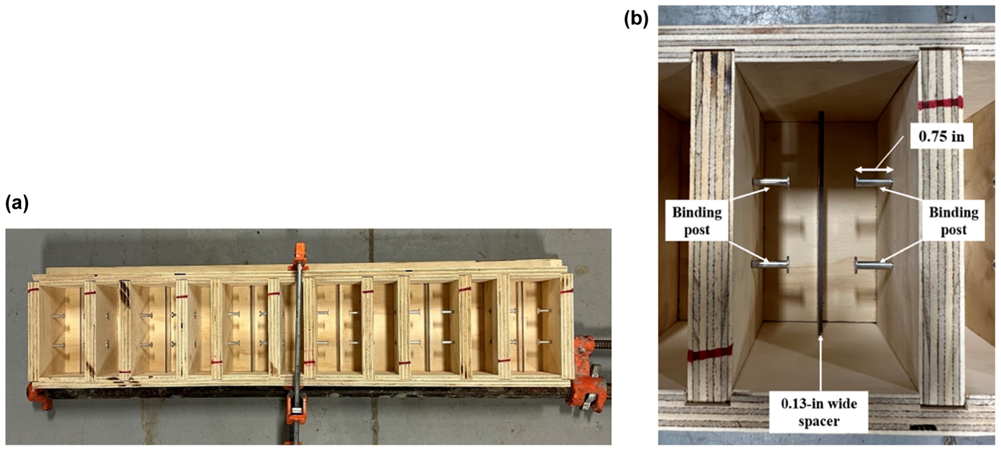
Form used for casting specimens: (a) full view (six molds) and (b) enlarged view (single specimen).
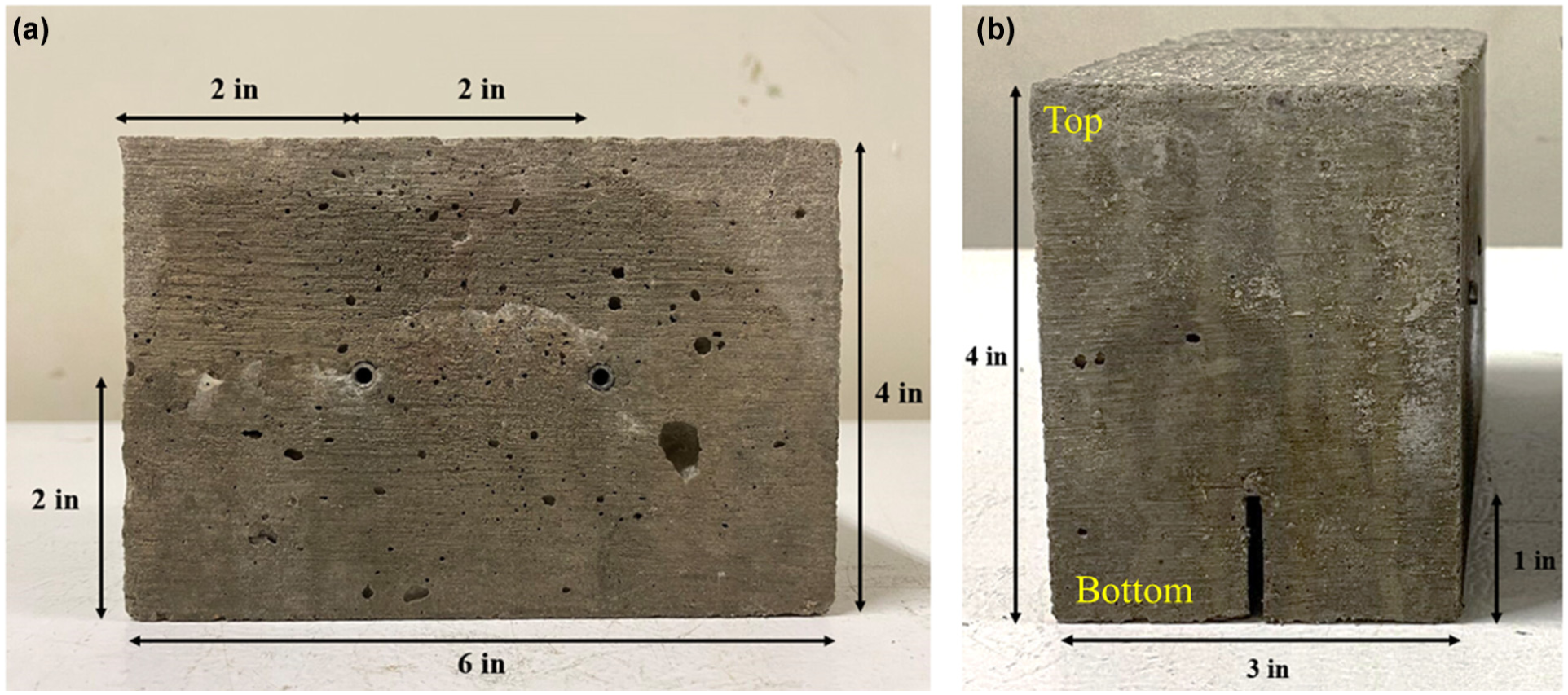
Cast specimen: (a) side view and (b) front view.
The concrete mixture used to cast the specimens represented a typical slipform paving mixture in Pennsylvania with a 0.42 water-cement ratio and limestone coarse aggregate sourced from Greer Limestone ( 19 ). Based on the US Geological Survey results for Morgantown, WV, it is believed that this is a dolomitic limestone ( 20 ). FHWA has released a technical brief stating that silicone sealants can be sensitive to certain dolomitic limestone aggregates (e.g., river gravel) compared with other aggregates ( 5 ). This may result in poor bond quality between the sealant and the concrete. The bond of the sealant to the limestone aggregate will be specifically evaluated as part of this study, since this limestone source is commonly used for constructing pavements in western Pennsylvania. The mixture, made with Type IL cement, had an average slump of 5.75 in. and air content of 5.6%. Mixing procedures, as well as slump and air testing, followed ASTM standards ( 21 – 23 ). Specimens were demolded after 24 h and wet cured for 7 days, as per ASTM C192 ( 22 ). The average compressive strength at 28-days was 5,700 psi, which was measured following ASTM C39 ( 24 ).
After 3 days of curing, when the compressive strength reached 3,500 psi, the reservoir was sawed into the top of the specimen. A saw cut was then made that ran the full depth of the specimen at the joint. Both halves of the sawn specimens were thoroughly cleaned with water and a utility brush and then dried with compressed air. This procedure ensured a consistent, clean surface for the sealant to adhere. Closed-cell backer rod was installed into the specimens to be sealed, which ensures that the asphalt and silicone sealants are placed at the appropriate depth. The silicone sealant was placed in the lab within 2 days after sawing/cleaning the reservoir. The asphalt sealant was placed by a contractor out in the field, approximately 1 month after casting. Further details on the construction of the specimens are available in Vandenbossche et al. ( 1 ).
An example of each specimen type is shown in Figure 5. Each half of the joint for every specimen is arbitrarily labeled as side A or side B, which is used during installation into the fatigue load frame, described later. A plastic spacer is inserted into the bottom of the joint to maintain the correct reservoir shape during storage and transport of the specimens. Additionally, hook-and-loop straps are used to securely hold the specimen together.
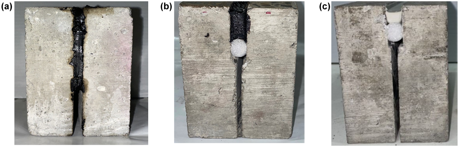
Examples of (a) asphalt filled, (b) asphalt reservoir, and (c) silicone reservoir specimens.
Test Procedure
The effect of fatigue on sealant performance was evaluated as follows. First, the extensibility of the sealant for each joint design was measured for specimens that were not fatigued. The other specimens were subjected to six freeze-thaw cycles. Then, 850 joint opening/closing cycles and 5,000 simulated vehicle loadings were applied, simulating 7 years of pavement service life. This process was repeated six times, simulating 42 years of fatigue exposure. Realistic loading conditions were identified using in situ strain data from an instrumented JPCP. These specimens were then tested for extensibility. Three replicates were tested for each parameter. Details of each of these components of the laboratory study are provided below.
Simulating 7 years of joint opening/closing and vehicle loading at a time allowed the researchers to analyze the deterioration to the joints at incremental points throughout the life of the pavement. Additionally, based on preliminary results, most joint sealant materials and reservoir designs did not exhibit significant deterioration until nearly 30 years of simulated joint opening/closing and vehicle loading. The silicone sealed joints did not develop any noticeable adhesive or cohesive failures after 42 years of simulated loading ( 1 ). Therefore, it was decided that the testing period would simulate the life of a concrete pavement up until the point of reconstruction to analyze the impact of cold weather joint opening/closing and vehicle loading on the different joint designs.
It should be noted that this investigation did not consider the effects of aging resulting from oxidation. Solar radiation typically has a more significant impact on asphalt sealant than silicone sealant. Oxidation of the asphalt results in an increase in the stiffness and makes it less pliable. For silicone sealants, exposure to ultraviolet radiation can result in a degradation of the sealant. It is recommended that the impact of these environmental effects be evaluated in future studies.
Freeze-Thaw Exposure
Each specimen was subjected to freeze-thaw cycles to simulate winter conditions. Before freezing, specimens were saturated in a cure room. Freeze-thaw action can damage the sealant or its bond with concrete because of water expansion and contraction. Freezing was performed in a freezer chest with a minimum temperature of −10°F. Saturated specimens were placed in baskets at the bottom of the freezer, while two non-sealed specimens with embedded thermocouples were used to monitor the internal temperature of the concrete specimens.
Specimens remained in the freezer until the internal temperature reached 5°F, which took approximately 7 h. This temperature was selected based on in situ data collected from a heavily instrumented pavement section of the SR-22 road in Murrysville, PA, which represents the average daily low pavement temperature in the winter minus two standard deviations ( 25 ). Afterward, specimens were transferred to a cure room (in accordance with ASTM C192) for 2 h until they stabilized at 73°F, and the specimens were re-saturated (see Figure 6) ( 22 ). This cycle duration allowed one freeze-thaw cycle to be completed per workday. The re-saturation of the specimens ensures that moisture is present in and around the joint for each freeze-thaw cycle, which is expected to accelerate joint sealant damage.
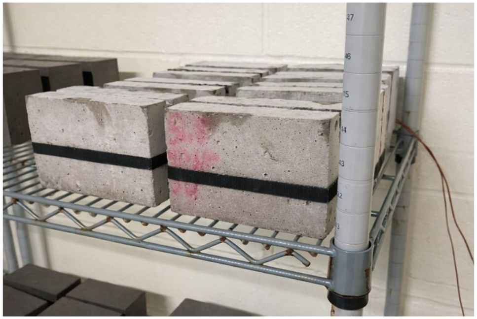
Specimens in the cure room at the beginning of the thaw cycle, with the thermocouple-embedded specimens against the back wall.
Each sealant material is required to meet freeze-thaw performance criteria (ASTM C920). Preliminary freeze-thaw testing was performed by subjecting each specimen design to 25 freeze-thaw cycles to observe if the changes in temperature were sufficient to affect the stiffness of the sealant. It was found that there was no visual damage accumulation for any of the specimens, but there was a slight decrease in sealant stiffness after the first few cycles. Therefore, it is believed that, although additional freeze-thaw cycles could potentially contribute to the degradation of the bond, it appears that the effects of changes on the properties of the sealant stabilized. It is recommended that additional freeze-thaw cycling be tested in future studies.
Fatigue Resulting from Joint Opening/Closing
The loading configuration used to simulate joint opening and closing is shown in Figure 7. This small-scale setup includes a 5.5 kip hydraulic actuator in displacement control to replicate joint opening/closing. Side A of the specimen was fixed to a base plate, while side B was attached to a top plate connected to the actuator’s load cell. The actuator displaced side B in a haversine wave at 1 Hz. Each specimen underwent 850 joint opening/closing cycles, representing 7 years of service.
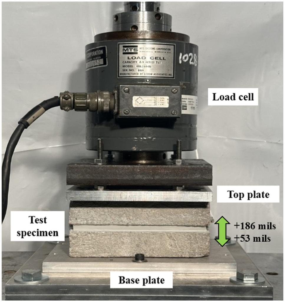
Joint opening/closing fatigue setup.
A heavily instrumented section of the SR-22 road near Murrysville, PA, established the in situ thermal conditions of a typical Pennsylvania JPCP ( 25 ). Pavement temperatures at slab mid-depth during January, February, November, and December, 2014, were used to calculate theoretical joint opening/closing. Based on the data collected from the SR-22, a temperature range of between 20°F and 50°F was determined to accurately represent the expected pavement temperatures in the winter months in Pittsburgh, PA. A target sealant temperature of 20°F was obtained before placing the specimen in the load frame. The sealant temperature at the end of the joint opening/closing fatiguing was approximately 50°F. The sealant temperature was monitored throughout the test with images taken with an FLIR E50 infrared camera (Figure 8).
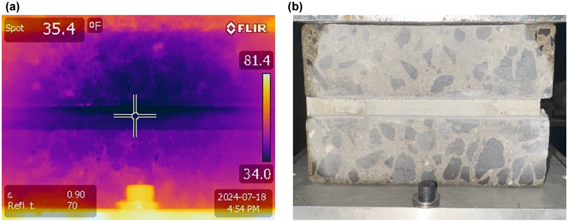
Joint opening/closing fatigue: (a) infrared photo and (b) corresponding specimen.
In situ temperature data from the SR-22 was also used to estimate typical joint opening/closing during the winter months in Pittsburgh, PA. January and February are typically colder than November and December, based on the in situ temperature data, which corresponds to a greater joint opening. The average daily pavement temperature for January and February in 2014, minus two standard deviations, was found to be 10°F, which can be considered an extreme temperature event. This temperature can be correlated to a joint opening using Equation 1, which is a revised version of the equation to estimate joint movement, established by Vandenbossche et al. ( 1 ). The pavement parameters used to calculate the estimated joint movement are listed in Table 1.

where
L = initial slab length (in.),
ΔT = temperature change (°F),
α = laboratory measured concrete CTE (10−6/°F),
The theoretical joint opening for this condition is +93 mil using the joint reservoir design parameters in Pennsylvania. During shakedown testing, no degradation was observed when fatiguing at these joint openings, so the values were re-evaluated. Next, it was assumed that only every other joint activated, making the effective slab length 30 ft. Then, the expected joint opening would be +186 mil. These joint openings were incorporated into the testing regime (previously described) in the following manner. The specimen is 20°F when it is placed into the load frame. The joint is opened to +119 mil. After the force stabilizes, a haversine wave with a minimum displacement of +53 mil and a maximum displacement of +186 mil is applied at a frequency of 1 Hz. A total of 850 cycles are applied. The specimen is then set back to its original position and is removed from the load frame. The condition of the sealant is assessed (permeability and stiffness), and then the complete procedure (fatiguing and condition assessment) is conducted five more times, for a total of six iterations. Details of the sealant condition assessment can be found in Vandenbossche et al. ( 1 ). It should be noted that the assessment of the permeability of the joint requires saturating the joint with water. This procedure ensures that moisture is present in and around the joint for each loading sequence.
Joint Movement Input Parameters
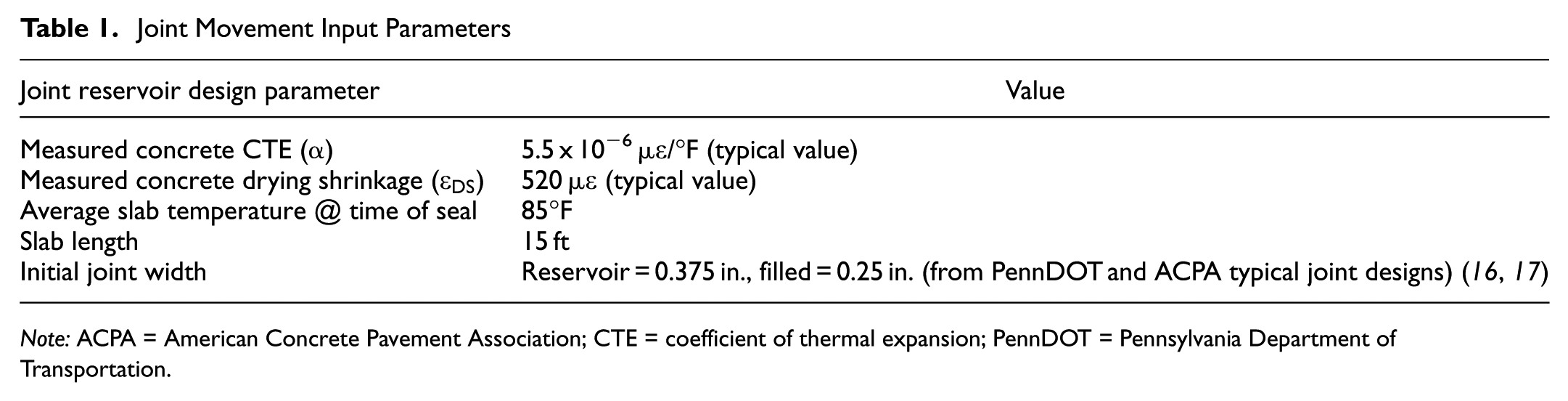
Note: ACPA = American Concrete Pavement Association; CTE = coefficient of thermal expansion; PennDOT = Pennsylvania Department of Transportation.
Fatigue Resulting from Vehicle Loads
To simulate a realistic JPCP joint life cycle, vehicle load effects were also considered. A fatigue loading frame (Figure 9) was used to replicate a vehicle crossing a transverse joint, causing differential deflection between the approach and leave slabs. Side A of the specimen was fixed to a bottom support, while a spacer beneath Side B prevented shear stress during installation. Side B was connected to a top arm linked to a 5.5 kip actuator.
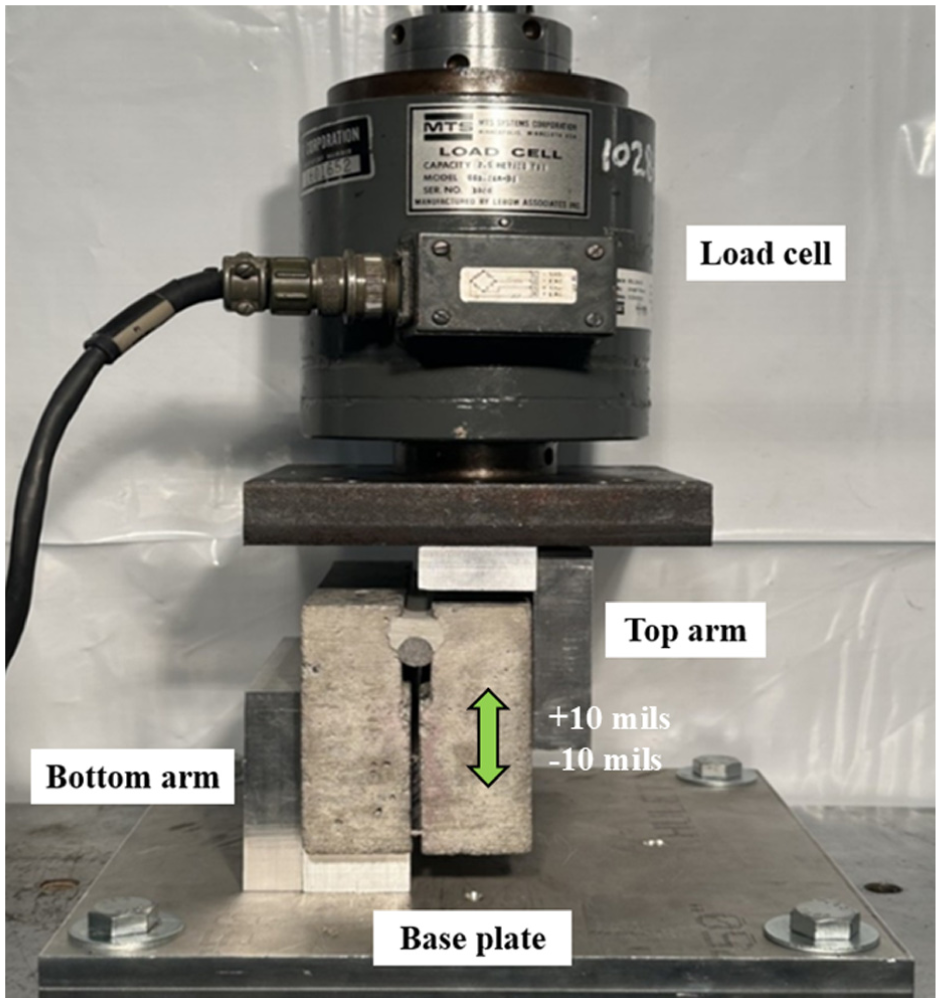
Load setup for simulating vehicle loads.
Testing was conducted at 20°F. Once the specimen was installed, the spacer was removed, and side B was displaced ±10 mil in a haversine wave at 5 Hz for 5,000 cycles in displacement control. This displacement reflects the maximum allowable relative deflection in doweled concrete pavements ( 26 ). The test simulates 7 years of winter truck loading, assuming 6,000 daily trucks with 0.1% producing critical 10 mil deflections. Sealant temperature was monitored using an infrared camera. After loading, the specimen was removed, secured with a hook-and-loop strap, and evaluated for condition. This process was repeated five more times for a total of six iterations.
Condition assessments were performed after joint opening/closing and after vehicle load simulations. It was found that joint sealant deterioration only occurred in response to joint opening/closing, and not to vehicle loading. Therefore, it was concluded that shear loading did not contribute to joint deterioration for any of the specimen designs after simulating 42 years in the field.
Extensibility
Quantifying the change in performance from the beginning to the end of the sealant life is critical in determining the impact of freeze-thaw exposure and fatigue conditions on the sealant. The change in extensibility at failure between newly sealed joints and sealants after 42 years of simulated in-service conditions was evaluated. The test began by placing the specimen into the load frame used for the joint opening/closing fatigue testing (Figure 7), which only loads the specimen in tension. The joint of the specimen was then opened 4.0 in. from its original sealed width at a rate of 2.0 in./min. This is an accelerated rate, compared with the extensibility testing defined in the standard ASTM D5329 bond test, but has been shown in previous studies to be effective ( 2 , 27 ). The temperature of the specimen at the time of testing was 30°F. This represents the average pavement surface temperature in the winter months when the joints would be fully opened, based on the data collected for the SR-22. The temperature of the sealant was monitored using an infrared camera. The sealant temperature, force, displacement, and the mode of failure were monitored throughout the test. Failure of each specimen was based on visual inspection and the peak tensile force during the test. The temperature at failure and mode of failure (adhesive and/or cohesive) were documented. Three replicates were tested for each test cell in the experiment design.
Results
This section describes and compares the results of the extensibility testing with summarized results, provided in Table 2. Typical load versus displacement curves for each sealant type are shown in Figure 10. “Failure” is defined as the time when the peak force is recorded, which is synonymous with the time that adhesive/cohesive failures initiate. It can be seen in the graph that the load required to open the joint is greater for the asphalt than the silicone, because the asphalt is significantly stiffer than the silicone at winter temperatures, which is representative of the test temperatures. The stiffer sealant will result in higher stress at the same strain.
Summary of Results from Extensibility Testing
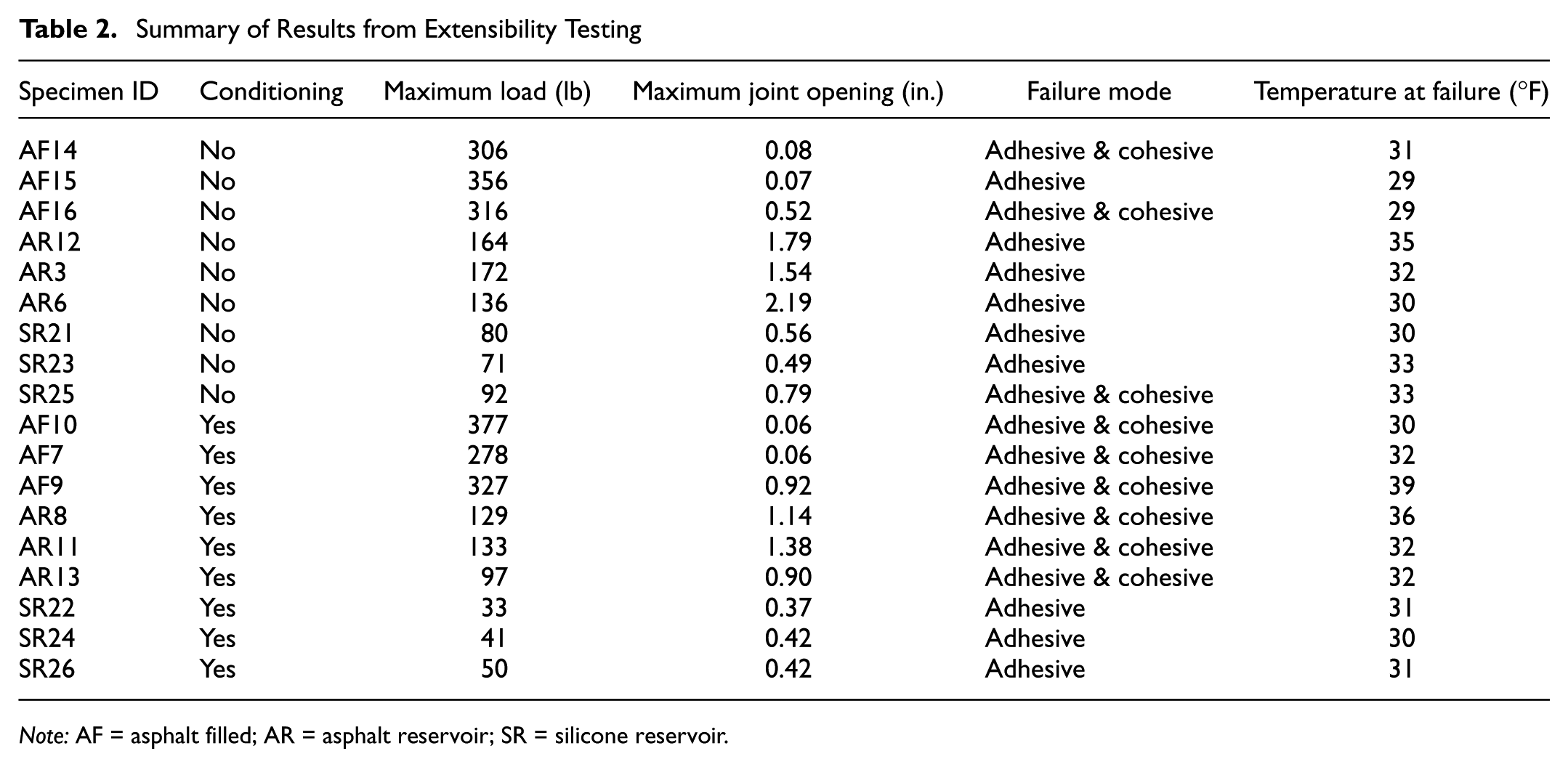
Note: AF = asphalt filled; AR = asphalt reservoir; SR = silicone reservoir.
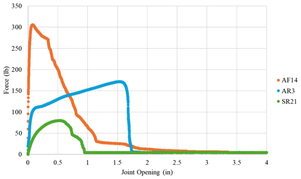
Typical force versus joint opening relationships for newly sealed specimens.
Joint Opening at Failure
The average and standard deviation of the joint opening and joint width at failure are provided in Table 3. It should also be noted that the standard deviation is quite high for the asphalt filled specimens. This reflects the difficulty in uniformly filling the joint, even under the ideal sealing conditions which existed. The joint width at failure was determined by adding the initial width of the reservoir (0.375 in. for asphalt reservoir and silicone reservoir or 0.25 in. for asphalt filled) to the joint opening at failure. The average and standard deviation of the difference in joint opening at failure are shown graphically in Figure 11. The asphalt reservoir specimens had the largest joint opening before failure, followed by the silicone reservoir, and then the asphalt filled. The newly sealed asphalt reservoir specimens opened 1.67 in. before failing. The newly sealed silicone reservoir specimens failed at an opening of 0.61 in. (narrower by more than 2.5 times). Two of the three newly filled asphalt filled specimens failed at an opening of 0.07 in. (narrower by more than 24 times). The joint opening/closing throughout the year for the SR-22 Smart Pavement, provided in Figure 12, shows that the change in joint opening throughout the year varies between 40 and 70 mil. These openings would be sufficiently large to fail one of the freshly sealed and two of the conditioned asphalt filled joints. It should be noted that these changes in joint opening are just the result of daily changes in temperature and do not include the additional opening that occurs in the field from long-term drying shrinkage.
Joint Characteristics at Failure for Extensibility Test
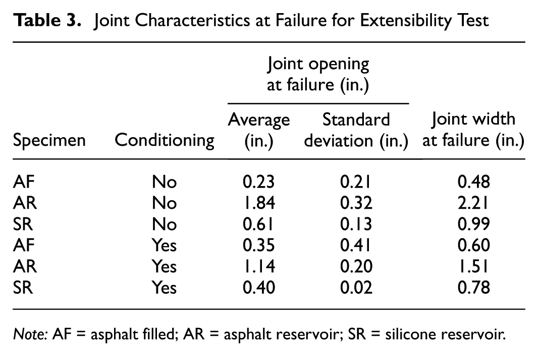
Note: AF = asphalt filled; AR = asphalt reservoir; SR = silicone reservoir.
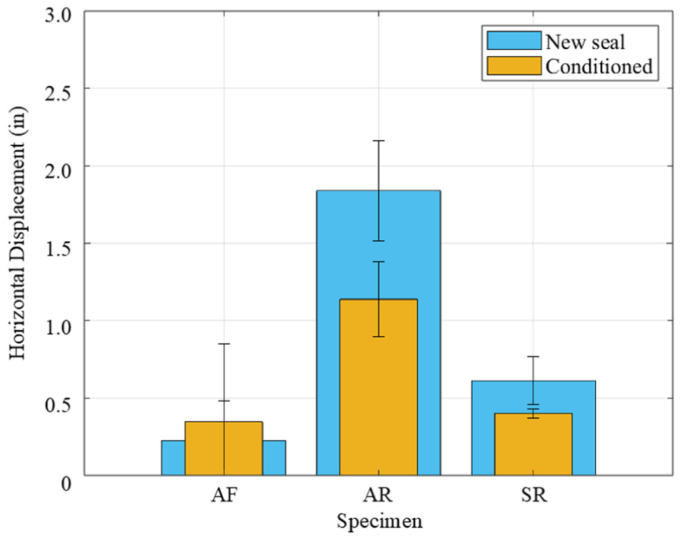
Joint opening at failure.
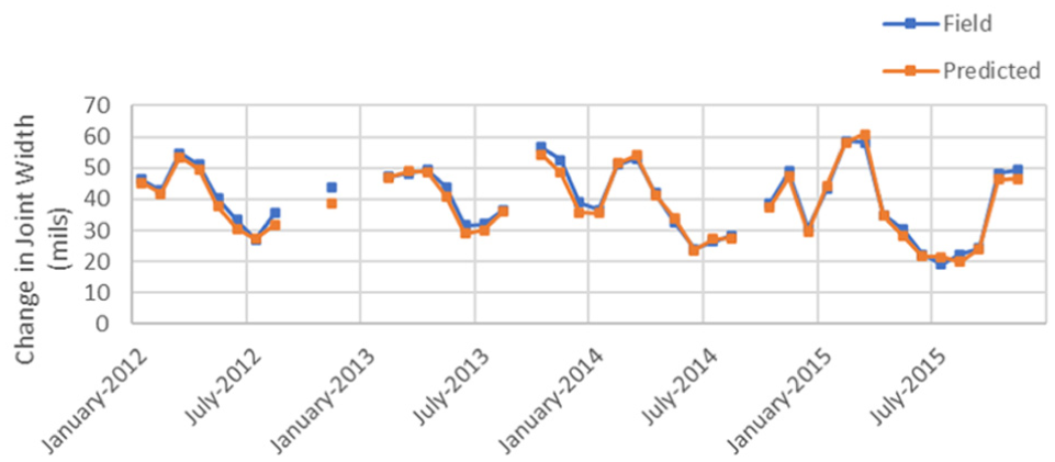
Field estimated versus predicted average monthly change in joint width at the top of the slab in the corners on the SR-22 road in Murrysville, PA.
The joint widths of the specimens at failure (Table 3) can be compared with the joint widths observed for pavements in Pennsylvania to assess the potential for failure in the field. The joint widths measured for the Smart Pavement on SR-22 after approximately 18 years in service were between 0.50 and 0.63 in., with an average of 0.58 in. These joint widths were measured in the fall with a pavement temperature around 72°F. A recent field survey of pavement joints on seven roadways in Pennsylvania documented joint widths up to 0.59 in. before resealing ( 28 ). This would be equivalent to a joint opening of about 0.25 in. Table 3- shows only the asphalt filled joint failed at openings significantly narrower than this. It should be noted that these joint widths are excessively wide, based on the original saw cut width of 0.375 in. This most likely occurs when sealants begin to fail, allowing incompressibles into the joints during the colder months. These sealant failures can occur early on in the pavement life if all joints do not activate before sealing, as this results in non-activated joints being undersealed, and activated joints being over-sealed. The undersealed joints are prone to sealant failure once all joints activate. Premature sealant failure can also occur as a result of poor construction practices during sealing. The incompressibles in the poorly sealed joint prevent closure during the summer months as the pavement temperatures increase and the concrete expands. This sustained stress will dissipate through creep, thereby effectively increasing the joint width at which the zero-stress state occurs. During the subsequent winter, when the slab contracts with decreasing temperatures, a wider joint width will be observed as a result of this change in zero-stress state. The cyclic yearly occurrence of this process will result in a progressively wider joint width over time that cannot be predicted using current joint width prediction equations. This explains why the predicted increase in joint opening during the winter would be about 0.1 in. for a maximum joint width of 0.475 in. for a typical 15 ft JPCP in Pennsylvania, but the joint widths noted in the field reviewed during summer months were commonly between 0.51–0.58 in. and 0.50–0.63 in. on road SR-22 ( 28 ).
The extensibility test was also used to evaluate the degradation of the sealant from freeze-thaw cycles and fatiguing. Table 3 shows the joint widths at failure were 0.60, 1.51, and 0.78 in. for the asphalt filled, asphalt reservoir, and silicone reservoir specimens, respectively, after conditioning. The reduction in performance resulting from the simulated 42 years of fatigue and the freeze-thaw cycles would not be sufficiently large for the asphalt and silicone reservoir specimens to fail, even with the larger joint widths observed in the field. Again, significant variability is observed for the filled joints, reflecting the difficulty in placing the sealant in the narrow joint and obtaining a uniform seal. The effect on the reduction in performance of the silicone sealant after an equivalent 42 years of fatigue was significantly less than that for the asphalt sealant. The average reduction in joint opening at failure resulting from conditioning was 0.53 in. for the asphalt reservoir compared with only 0.21 in. for the silicone reservoir specimens. This corresponds to a reduction in joint movement of 38% and 32%, respectively, compared with the joint movement at failure before conditioning.
Strain at Failure
When designing the reservoir, the width at which the reservoir is sawed is determined by multiplying the allowable strain for that sealant material by the calculated maximum joint opening. Therefore, the allowable strain for each sealant material can be compared with the ultimate strain at the mid-depth of the sealant for the laboratory specimens. The mid-depth ultimate strain is calculated by dividing the joint opening at failure by the width of the reservoir saw cut. As previously stated, the allowable strain for an asphalt sealant is typically 0.25, and 0.5 for silicone. These values should be substantially less than the ultimate strain, as the ultimate strain occurs at failure and allowable strain occurs repeatedly throughout the life of the sealant. The ultimate strain at the mid-depth of the sealant is shown graphically in Figure 13.
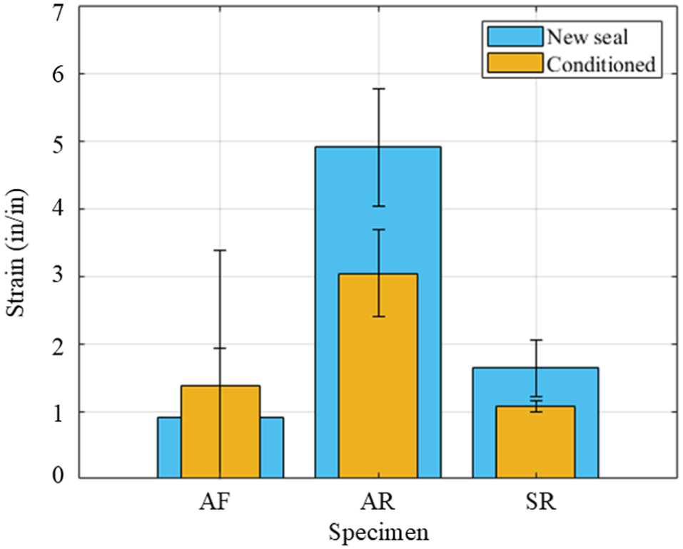
Mid-depth strain at failure.
It is shown that the asphalt reservoir joint experiences a significant amount of strain at failure for both the freshly sealed and conditioned (4.9 and 3.0 in./in., respectively) compared with the other design alternatives. Even after experiencing a simulated 42 years of joint opening/closing and vertical displacement caused by vehicle loads, the asphalt reservoir joint was extended over three times the initial width before failure. The asphalt filled joint can withstand only a fraction of this joint movement before failure, which failed at strains of 0.9 and 1.4 in./in. for the specimens without and with conditioning, respectively. The strain at failure for silicone specimens falls between the asphalt sealant alternatives, that being 1.6 and 1.1 in./in. for specimens without and with conditioning, respectively. While the difference between the strain at failure for the asphalt and silicone sealed reservoirs is statistically significant at a 95% confidence level, this is not the case for the asphalt filled joint, as there is a large amount of variability between specimens for this design/sealant configuration, as previously discussed. It is also interesting to note that the strain at failure is approximately 6 to 12 times (for asphalt) and 2 times (for silicone) the recommended allowable “working” strain suggested by the manufacturers (0.25 for asphalt; 0.5 for silicone). It was noted previously that dolomitic limestone aggregates can be sensitive to silicone sealants, resulting in poor bond quality. However, this behavior was not seen in the specimens for this study. As shown in Figure 14, the silicone sealant was seen to be able to adhere to the limestone aggregates, based on a forensic analysis after extensibility testing. Therefore, the difference in sealant strain before failure for the silicone reservoir specimens is not attributed to the limestone aggregate in the concrete substrate.
Conditioned silicone sample after extensibility testing.
It should be noted that aging resulting from oxidation and weathering is not considered. Oxidation causes a change in the chemical composition of the asphalt that contributes to an increase in stiffness and a decrease in resilience ( 29 ). This increase in stiffness translates into higher stress for equivalent strains, which reduces the ultimate strain at failure. Silicone sealants are resistant to the effects of oxidation, but can exhibit a reduction in stiffness as a result of exposure to ultraviolet radiation, although at a slower rate than the oxidation of the asphalt ( 30 ).
Failure Mode
The failure mode can be used to identify the stress type (adhesive or cohesive) dictating failure. The failure mode was documented at the conclusion of each extensibility test to determine if the failure initiated within the sealant (cohesive), between the sealant and the concrete (adhesion), or both. As was anticipated, the increase in the width of sealant installed and use of a backer rod with the reservoirs decreased the tensile strains and corresponding stresses within the sealant when the joint was opened. This shifted the failure mode from primarily adhesion to both adhesion and cohesion. The specimens with a sawed reservoir failed in adhesion 67% of the time compared with only 17% of the time for the asphalt filled joints (see Table 2). The asphalt reservoir joint only exhibited adhesive failures before fatiguing, but then exhibited both adhesive and cohesive failures after conditioning. This could be an indication that the asphalt became less pliable or accumulated damage during the conditioning. The silicone sealant reservoir design with the 1:1 shape factor results in a substantially smaller bond area between the sealant and concrete than the other joint designs (1.6 times and 3.8 times less area than the asphalt reservoir and asphalt filled joints, respectively). This translates to higher debonding stresses, which can contribute to adhesive failures.
Cohesive failures were commonly exhibited in the asphalt filled specimens. Small pebbles and debris can become lodged in the regions of the sealant where the cohesive failures develop during the winter months when the joints are wide, which then results in a build-up of stress during the summer months when the joints close. This can contribute to spalling or even blowups. An example of the typical cohesive failures observed is shown in Figure 15. These failures can be partly attributed to the difficulty in fully filling the narrow joint, which led to voids/gaps in the sealant that act as stress concentrations. The average measured void area for the conditioned asphalt filled joint was 3.25 in.2 with a standard deviation of 0.20 in.2. This means that 23% of the asphalt filled surface area consisted of voids/gaps by the end of the extensibility test. Also, the strains for the asphalt filled specimens were larger than the other designs at equivalent joint openings, as the initial joint width at the time of sealing was significantly narrower. This resulted in the initiation of cohesive failures at narrower joint openings than the asphalt and silicone reservoir joints. By designing a wider initial joint width and the use of a backer rod, these cohesive failures can be mitigated by reducing the strain within the sealant and reducing the likelihood of a poorly filled joint.
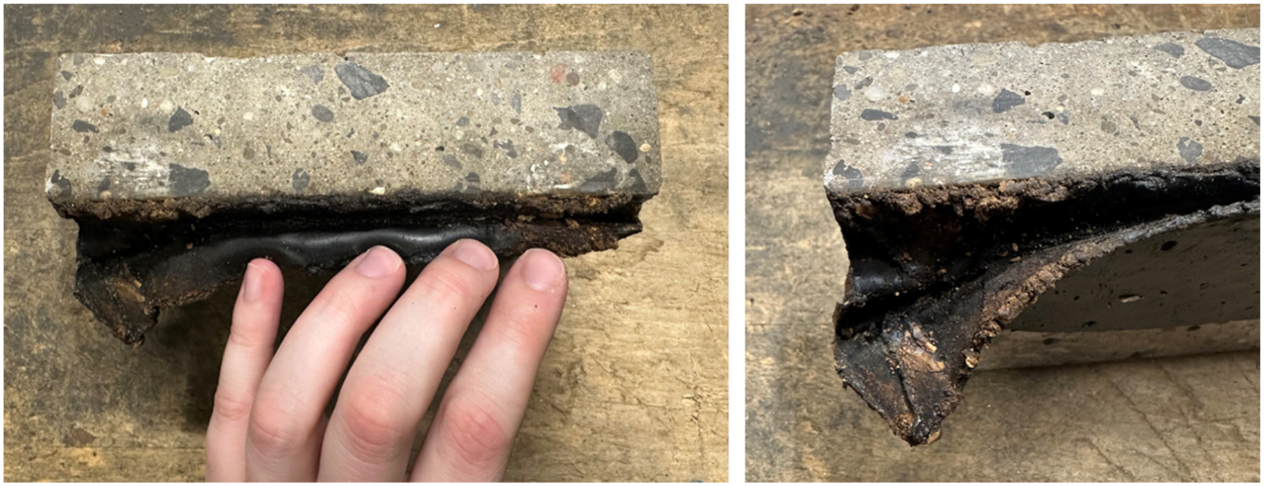
Typical cohesive failure for asphalt filled specimen: full length of specimen (left) and region of most damage (right).
Stress at Failure
The adhesive stress at failure was determined by dividing the peak load at failure by the cross-sectional area of the sealant at the interface of the concrete reservoir wall. The theoretical cross-sectional area at each interface for the asphalt reservoir, asphalt filled, and silicone reservoir designs were 6.00, 14.25, and 3.75 in.2, respectively. However, as shown in Figure 16, in one of the asphalt filled joints it was seen that the surface area of the sealant was less than the target value (13.25 in.2 compared with the 14.25 in.2 design). This reduced surface area was likely caused by the inability to adequately fill the narrow joint. This difference in designed and actual sealant surface area contributed to the variability within the data for the asphalt filled joints.
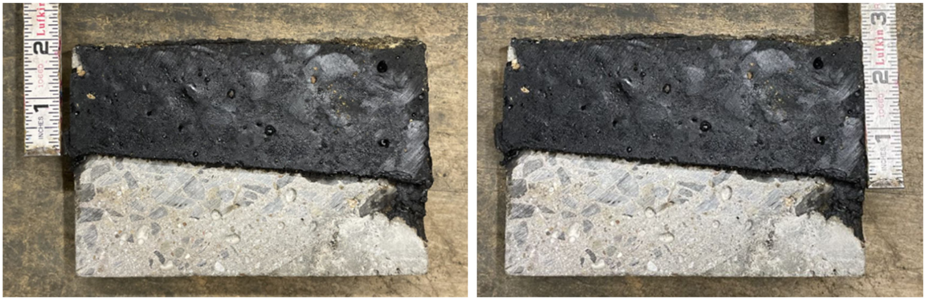
Example of a poorly filled joint with areas of shallower sealant depth (left) and larger sealant depth (right).
The adhesive stress at failure is shown in Figure 17. The asphalt reservoir experienced the largest adhesive stress at failure (26 psi for newly sealed and 17 psi for conditioned specimens), followed closely by the asphalt filled (23 psi for newly sealed and 23 psi for conditioned) and silicone reservoir specimens (22 psi for newly sealed and 11 psi for conditioned). When the specimen failed purely in adhesion, this stress at failure provides an estimate of the adhesive strength. The adhesive strength for the silicone specimens failing in adhesion was approximately 22 psi both with and without conditioning while that for the asphalt newly sealed asphalt specimens was (26 psi) was slightly greater.
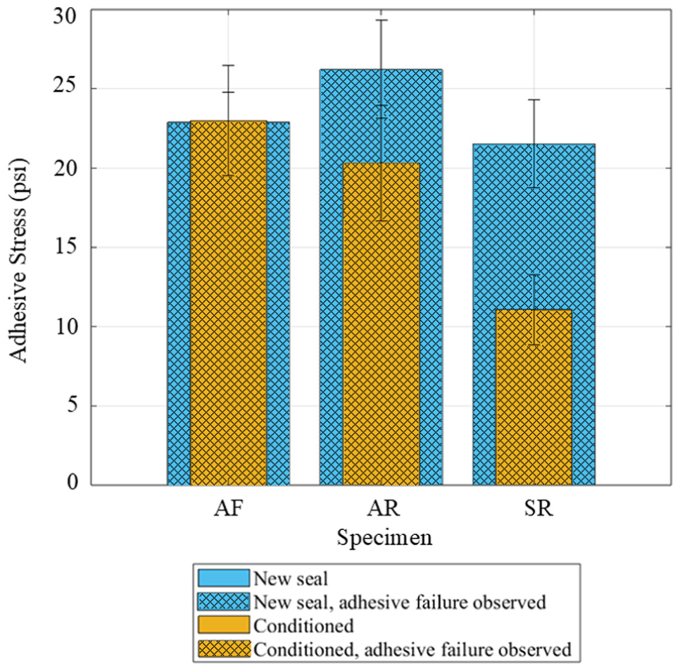
Adhesive stress at failure (cross-hatching indicates failure mode).
The adhesive stress at failure for the asphalt filled specimens is also approximately the same for both the newly sealed specimens and specimens that had been subjected to conditioning. This implies that the asphalt filled specimens that have been conditioned undergo the same stress at failure as the newly sealed specimens, but at a lower strain value, indicating that they become less pliable and more susceptible to damage with aging.
Since stress at failure is a function of the force normalized by the bonded area and the stiffness and bond strength of the material, it would be anticipated that the adhesive stress at failure should be the same for both the asphalt reservoir and filled specimens, since the stiffness and strength of the asphalt sealant are the same. However, the asphalt filled specimens failed at lower adhesive stress levels. This is because both adhesive and cohesive failure occurred simultaneously in the asphalt filled specimens. Also, small voids/gaps resulting from the difficulty in filling the narrow asphalt filled joint can lead to stress concentrations resulting in lower opening forces at failure. The higher stiffness of the asphalt at the lower test temperatures results in the development of higher adhesive stresses in the asphalt reservoir at the same joint opening than the silicone reservoir specimens. The shape factor (W:D) is also significantly higher (less material is required) for the silicone sealant, resulting in a substantially smaller area (6.00 in.2 versus 3.75 in.2) where the sealant is bonded to the concrete. This increases the magnitude of the stress that develops for the silicone reservoir compared with the asphalt reservoir at equivalent joint openings. Increasing the depth of the silicone sealant to that of the asphalt by applying the same shape factor would reduce the stress considerably. The asphalt reservoir and silicone reservoir specimens exhibited a statistically significant (at a 95% confidence level) reduction in stress of 34% and 49%, respectively, at failure after being exposed to 42 years of fatigue and freeze-thaw cycles. The joint opening at failure was decreased and the load required to achieve the joint opening was lower. Both contribute to the reduction in stress at failure when the specimens were conditioned before the extensibility testing.
The cohesive stress at failure was calculated by dividing the peak load by the cross-sectional area of the sealant along the length of the specimen corresponding to the opening at failure. The thickness of the sealant at midspan across the reservoir decreases as the joint opens, thereby creating a reduction in the cross-sectional area at this location and running parallel to the joint. The cross-sectional area corresponding to the joint opening at failure was calculated for each specimen and used to determine the cohesive stress at failure. Further information on derivation of the cross-sectional area can be found in Vandenbossche et al. and Tons, but will be excluded here because of space limitations ( 1 , 31 ). The cohesive stress at failure for newly sealed and conditioned specimens is shown in Figure 18. It is seen that the silicone reservoir specimens experienced the largest cohesive stress before failure. Yet, as shown in Table 2, only the silicone sealed specimen that exhibited the largest cohesive stress and joint opening (0.79 in.) at failure exhibited a cohesive failure, indicating that the actual cohesive strength is higher since the other specimens failed in adhesion. The asphalt filled specimens exhibited both cohesive and adhesive failures 60% of the time. It would be anticipated that the asphalt filled and asphalt reservoir specimens would fail at the same cohesive stress, but many of the specimens exhibited a mixed mode (cohesive and adhesive) failure.
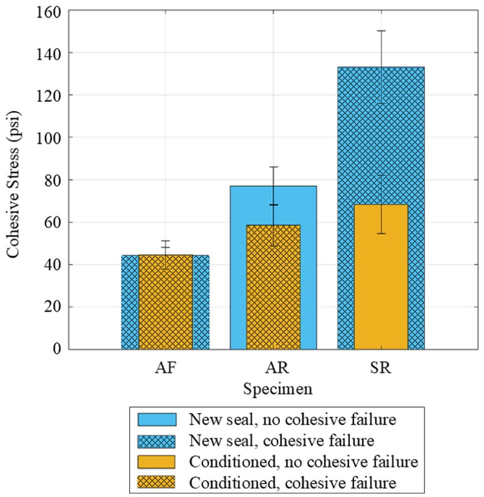
Cohesive stress at failure (cross-hatching indicates failure mode).
Because of the presence of a backer rod used for the asphalt reservoir and silicone reservoir specimens, it was expected that the strains that developed during joint opening would be greatest at the top of the sealant. These large strains at the surface of the sealant lead to the development of cohesive failures. As the cohesive failures propagate along the surface of the sealant, the stress in the bulk sealant material is dissipated at the surface, but it is believed that there is an increase in stress that develops at the interface between the sealant and the concrete as the stresses redistribute. This higher stress at the concrete interface leads to the development of adhesive failure, which propagates along the length of the joint, causing the sealant to peel away from the concrete wall. This phenomenon was seen for many of the asphalt filled and asphalt reservoir specimens where, first, cohesive failures developed, then adhesive failures followed. It was seen for several of the asphalt filled and asphalt reservoir specimens that the adhesive failure initiated along the surface of the sealant, which was expected. However, for the silicone reservoir specimens, cohesive failures were observed in only one specimen. By adopting a shape factor more similar to that of the asphalt reservoir design, it is anticipated that a larger joint opening at failure would be achieved, and the mode of failure would switch to cohesion. With a larger shape factor and a greater depth of sealant, the adhesive forces are dispersed over a larger surface area, leading to lower adhesive stresses for the same joint opening.
Conclusions and Recommendations
This study was conducted to quantify the effectiveness of standard PennDOT transverse joint reservoir designs for JPCPs. The designs considered for this study were asphalt filled, asphalt reservoir, and silicone reservoir design/material combinations. Concrete specimens were fabricated, sawed, and sealed to represent a section of a transverse joint. The difference in sealant extensibility was quantified by comparing specimens that had been exposed to freeze-thaw and fatigue cycles to newly sealed joints. The newly sealed asphalt reservoir, silicone reservoir, and asphalt filled specimens opened 1.84, 0.61, and 0.23 in., respectively, before failing. The joint opening/closing throughout the year for the SR-22 Smart Pavement was determined by Vandenbossche et al. and found to be between 0.040 and 0.070 in. ( 1 ) Based on these results, these openings would be sufficiently large to fail one of the freshly sealed and two of the conditioned asphalt filled joints. This indicates that an asphalt filled joint might be more appropriate for smaller slabs where smaller joint openings would be anticipated. Even though the filled joint is not necessarily meant to keep the joint watertight, the cohesive failures observed provide an opening in the sealant where pebbles and small debris could become lodged in the joint.
The strain at failure for freshly sealed and conditioned specimens was evaluated for each joint design: 4.9 and 3.0 in./in. for asphalt reservoir; 0.9 and 1.4 in./in. for asphalt filled; and 1.6 and 1.1 in./in. for silicone reservoir specimens. This is approximately 6 to 12 (for asphalt) and 2 (for silicone) times the recommended allowable “working” strain suggested by the manufacturers (0.25 in./in. for asphalt; 0.5 in./in. for silicone). The reduction in opening at failure for the silicone sealant after 42 years of simulated service life was 6% less than that for the asphalt sealant.
Newly sealed and conditioned asphalt filled specimens exhibited both adhesive and cohesive failure modes. Asphalt reservoir specimens exhibited only adhesive failures when newly sealed, but both modes after conditioning. Newly sealed silicone reservoir specimens exhibited both failure modes, but primarily adhesive failure after conditioning. The adhesive strength was slightly higher (22%) for the asphalt reservoir specimens than the silicone reservoir specimens before conditioning. This difference was statistically significant at a 95% confidence level. The performance of the silicone sealed reservoir could be improved by increasing sealant depth of sealant to achieve a shape factor closer to 2:1, as is used with asphalt sealant. Greater sealant depth increases the bond area and reduces adhesive stresses.
This study has shown that both the silicone and asphalt sealant material and reservoir designs evaluated are suitable to achieve long term performance for 15 ft JPCPs constructed in Pennsylvania. It should be noted that this silicone sealant did exhibit a good bond with the coarse aggregate even though a dolomitic limestone was used. This is assuming that the joints are sealed after all joints have activated through the full depth of the pavement. Otherwise, some joints will be under-sealed and others over-sealed once all joints activate, leading to premature sealant failure. In general, asphalt filled joints are not recommended for 15 ft slabs where larger joint opening/closings are expected, but are better suited for pavements with shorter slabs. Even though the intent for these designs is not necessarily to achieve a watertight seal, cohesive failures can develop. This provides the opportunity for small pebbles and debris to become lodged in the joint, leading to spalling and blow-ups. It should be noted that this investigation did not consider the effects of aging resulting from oxidation of the asphalt, which will increase the stiffness and make it less pliable, or a degradation of the stiffness of the silicone because of exposure to ultraviolet radiation. It is recommended that this be evaluated in future studies.
Footnotes
Acknowledgements
The authors gratefully acknowledge financial support from the Impactful Resilience Infrastructure Science and Engineering (IRISE) consortium at the University of Pittsburgh. They also thank Edward Skorpinski (Pennsylvania Turnpike Commission), James Young and Brandon Farrell (Gulisek) for coordinating site visits and field sealing of asphalt specimens; Lydia Peddicord (PennDOT) for field performance and sealant survey data; Tom Bryan (Bryan Concrete) and Justin Bryan (Neville Aggregates) for supplying admixtures and aggregates, respectively. Appreciation is also extended to Zachery Brody for his assistance with the literature review and testing protocol development, and to undergraduate researcher Jack Parkhurst for help with laboratory work and data processing.
Author Contributions
The authors confirm contribution to the paper as follows: study conception and design: J. Vandenbossche, M. Darnell; data collection: M. Darnell; analysis and interpretation of results: J. Vandenbossche, M. Darnell; draft manuscript preparation: J. Vandenbossche, M. Darnell. All authors reviewed the results and approved the final version of the manuscript.
Declaration of Conflicting Interests
The authors declared no potential conflicts of interest with respect to the research, authorship, and/or publication of this article.
Funding
The authors disclosed receipt of the following financial support for the research, authorship, and/or publication of this article: Funding and support was received through the Impactful Resilient Infrastructure Science and Engineering (IRISE) Consortium (Contract No. PITTIRISE2018).
Data Accessibility Statement
The data that support the findings of this study are available from the corresponding author on reasonable request.