
Abstract
Conventional railway sleeper (tie) lateral resistance tests often assess small lateral displacements (∼2 mm) and do not consider the vertical displacement (uplift) of sleepers through lateral plane rotation which, for installed sleepers, is constrained by the supported rail. Consequently, unrestrained tests tend to underpredict the lateral resistance achievable in service. This paper describes an alternative single sleeper push test (SSPT) methodology in which railway sleepers are restrained during laboratory lateral resistance tests, with a passive restraint system used to limit sleeper uplift. The lateral resistance of concrete and steel sleepers has been investigated using a SSPT in a ballast box with and without the use of the new restraint system. It has been found that, when unconstrained, both concrete and steel sleepers uplift, with the greatest uplift values seen for steel sleepers. In the more realistic restrained configuration, the lateral resistance of the concrete sleeper increased. The steel sleeper saw an even greater increase in lateral resistance and furthermore experienced a rising lateral resistance with increasing lateral displacements. An existing model was used, and expanded, to predict the buckling stability of track for both restraint conditions, with significantly lower minimum buckling temperatures found for both sleeper types when free to uplift. This study shows that partial restraint of sleepers, as imposed by the rail in track, has a tangible influence on the sleeper lateral resistance during push tests compared with unrestrained tests. The results of this study enhance the understanding of sleeper behavior during lateral track shifts, which has the potential to improve buckling risk mitigation strategies.
Keywords
The resistance to movement of sleepers in ballast tangential to the track direction (referred to hereafter as lateral resistance) is a key property of the track system, providing stability and playing a critical role in resisting movement of the track during buckling ( 1 ). The typical development of lateral resistance with respect to the lateral displacement of the sleeper moving through ballast consists of a rapid rise which levels off after a short distance (usually less than about 5 mm) and remains near constant thereafter. However, the compaction of the ballast and the type of sleeper can affect the shape of the curve, producing a slower rise or a lower resistance following a peak. Lateral resistance can be considered as the sum of the three components seen in Figure 1, which act on the bottom (Rb), side (Rs), and end (Re) of the sleeper. The Rb and Rs components are a result of frictional forces of the ballast against the sleeper as it moves, while the end pressure (Re) results from reaction forces of the ballast on the sleeper end.
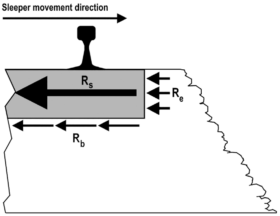
Components of sleeper–ballast lateral resistance for a side view of a sleeper in ballast.
Achieving large values of lateral resistance is highly desirable and is one of the main strategies for improving track safety when considering buckling resistance ( 1 ). Several methods to do this are available in the literature, such as consolidating the ballast, using lateral resistance end plates, adjusting the geometry of the shoulder, or using different types of sleepers ( 2 , 3 ). The material, mass, and shape of a sleeper can influence the magnitude and ratio of the components seen in Figure 1, and wooden, concrete, and steel sleepers each offer different lateral resistance values ( 3 , 4 ).
Significant differences exist between steel sleepers and their concrete monoblock counterparts. These geometric variations are shown in Figure 2, where the steel sleeper features a shell-like structure of a hollow inside and thin walls, while the concrete sleeper is a prism featuring a constant, filled cross-section. The difference in geometry also calls for different installation procedures, with steel sleepers requiring the ballast to be forced upwards and inside of the sleeper to fill the empty space of the shell design. Steel sleepers are also generally lighter than concrete sleepers and are comparable in mass with wooden types.
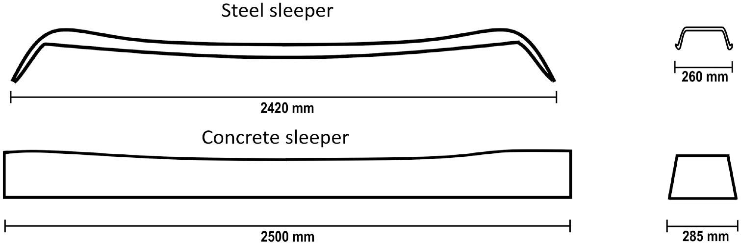
Side and end profiles of steel and concrete monoblock sleepers.
Within the published literature, a common method of testing the lateral resistance of a sleeper is to conduct a single sleeper push test (SSPT). As outlined by Le Pen and Powrie ( 5 ), in a laboratory setting, a sleeper is positioned in ballast and is displaced toward the shoulder (shown in Figure 3), with the load required to move the sleeper and the displacement recorded. On track, this test is performed by first unfastening the sleeper from the rail and then securing a ram to the sleeper and pushing off from the opposing rail ( 6 ). Alternatively, an entire track panel can be displaced in a track panel push test (TPPT) as described by De Iorio et al. ( 7 ). The track panel approach achieves higher measured lateral resistance values because of the flexural rigidity of the rail ( 8 ) and includes the summation of areas of influence from each individual sleeper ( 9 ). The SSPT is the most common test performed and is used as the basis for several British Standards. These include BS 500:2000 ( 10 ) for steel, BS EN 13230-6:2020 ( 11 ) for concrete, and BS EN 13145:2001 ( 12 ) for wood. Note that BS 500:2000 ( 10 ) outlines the specific procedure for testing lateral resistance properties, whilst its counterparts only state a required lateral resistance threshold.
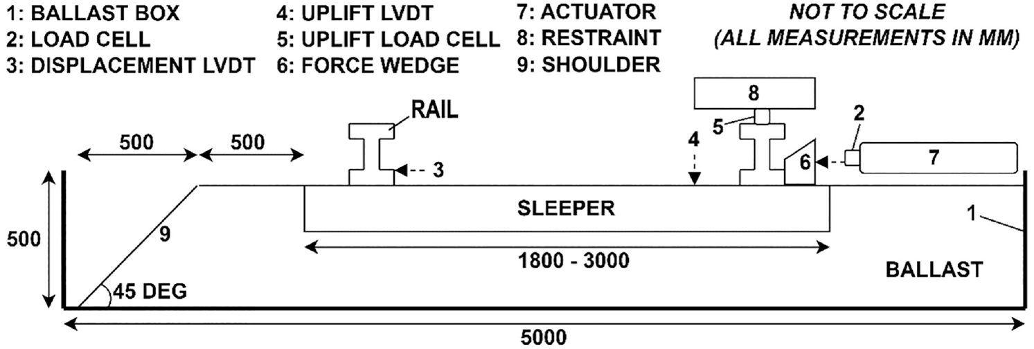
Sleeper test rig schematic.
While the lateral responses of wooden and concrete sleeper types are well documented, relatively little work has been done to investigate the lateral resistance of steel sleepers. Zakeri and Bakhtiary ( 13 ) performed single sleeper push tests to compare the lateral resistance of steel sleepers against concrete and wooden sleeper types, resulting in values of approximately 6.7 kN at 2 mm sleeper displacement with compacted ballast. Zakeri and Talebi ( 14 ), Zakeri et al. ( 15 ), and Jing et al. ( 16 ) investigated the increase in lateral resistance from installing stiffener webs and rubber pads inside steel sleepers. Both studies found that sleepers without additional stiffening measures reach approximately 4 kN lateral resistance, even with significant ballast compaction. In each of these studies, the SSPT is completed using a track panel and an unclipped sleeper and is typically performed in the field on existing sections of track. As an alternative to the quasi-static SSPT, Esmaeili et al. ( 17 ) considered the dynamic lateral resistance of steel sleepers through impact loading using a pendulum and compared the results against the static lateral resistance obtained through an SSPT. The static test for the steel sleeper generated values lower than those for the other sleeper types.
Initial exploratory SSPTs ( 18 ) of steel and concrete sleepers have been performed by the authors in accordance with BS 500:2000 ( 10 ), during which a rise in the vertical position of the sleepers (uplift) was noted. These tests were performed under laboratory conditions and found lateral resistance values close to those reported in the literature for small (<∼5 mm) displacements. However, over longer displacements, significant vertical movement was observed. This phenomenon is of interest as a potential source of disparity between the SSPT and the behavior of sleepers in track, where the weight and stiffness of the rail and sleeper as a combined structure would reduce sleeper uplift, if not eliminate it entirely. To the best knowledge of the authors, no work investigating the uplift of sleepers exists, neither in the abovementioned studies nor in the wider lateral resistance literature. This may be the result of many of the reported SSPTs being limited to a 2-mm maximum displacement, during which the uplift magnitude may not be significant enough to be noticed. While a short displacement limit may be acceptable for concrete sleepers where results show an assumption of constant lateral resistance past 2 mm could be made, based on the preliminary tests, this same assumption does not apply to steel sleeper types. Furthermore, as track buckles may exhibit a lateral track deformation of 300 mm and beyond ( 19 ), it is of interest to investigate SSPTs of longer displacements.
Based on the previously mentioned observations, this paper has two aims. The first is to report findings on the uplift behavior of sleepers during an SSPT through a longer push distance. The second is to quantify the influence of uplift on lateral resistance and the impact this has on the buckling stability of track. Both aims serve to examine the uplift behavior of sleepers under the influence of the greater track structure formed of the connected rails and sleepers, noting that sleepers are displaced during a track buckle. The findings of this research are of particular interest for understanding the behavior of steel sleepers, which were seen to exhibit greater uplift than concrete sleepers and for which the lateral resistance over longer displacements has not been investigated by other authors.
Methodology
To achieve the aims set out in the previous section, an alternative SSPT methodology has been designed. This involves the use of a guide restricting the vertical displacement of the sleeper; which represents the restraining forces of the rail and is hereafter called the partial uplift restraint. A steel and a concrete sleeper have been selected for comparison. While preliminary testing showed steel sleeper uplift to be the most prominent, concrete sleepers have also been considered as a means of comparison and to investigate the impact of sleeper shape and weight on uplift behavior. The test program involved firstly carrying out SSPTs for the two sleeper types in a ballast box with the vertical displacement of the trailing end of the sleeper limited by the restraint. Secondly, the tests were repeated for the same sleepers with no restriction on the vertical movement of the sleeper ends, recording the uplift displacement. For both tests, the lateral resistance of the sleepers was recorded. Finally, the lateral resistance profiles for both sleeper types and the two restraining conditions were applied in the buckling model developed by Grissom and Kerr, which was updated to allow for non-constant lateral resistance profiles.
Single Sleeper Push Tests
A ballast box of 5000 mm by 2500 mm by 500mm containing approximately 9 t of ballast graded in accordance with NR/L2/TRK/8100 ( 20 ) was built to test the lateral resistance of different types of railway sleepers at full scale in accordance with BS 500:2000 ( 10 ). The dimensions of the box, ballast, and shoulder can be seen in Figure 3. The ballast bed was formed coplanar to the sleeper top and the ballast shoulder angle was set to approximately 45° (the angle of natural repose), with the shoulder at a distance of 500 mm from the end of the sleeper.
The W560H steel sleeper and the G44 concrete sleeper were tested using the configuration above. The sleepers were assembled with pads, appropriate fasteners, and a rail section equivalent to the weight of the rail supported by a single sleeper in installation. The test did not include any additional downward weight on the sleeper (e.g., because of vehicles). The uplift of the rail caused by the precession wave before and after a moving vehicle was not considered in the scope of the tests. The lateral load was exerted on the sleeper using the Thomson 60 kN linear actuator seen in Figure 4. The actuator was positioned at the end of the sleeper furthest from the ballast shoulder (trailing end), with its centerline 75 mm above the top face of the sleeper to give clearance in case of sleeper uplift. A downward-angled wedge (item 6 in Figure 3), not fixed to the sleeper, was used as an interface between the actuator head (item 7) and the sleeper to transfer the force of the actuator to the fastener. This configuration allowed a horizontal force to be exerted on the sleeper at a low position, thus minimizing the moment on the sleeper while giving enough clearance to keep the actuator safe from damage caused by sleeper vertical movement. The horizontal and vertical sleeper displacements were monitored directly by Penny & Giles SLS130 (item 3) and Caldaro S1SF (item 4) linear variable differential transducers (LVDTs), respectively. The horizontal and vertical loads generated by the sleeper were measured by a VPG 50-kN (item 2) and two GLBM 20-kN (item 5) load cells, respectively.
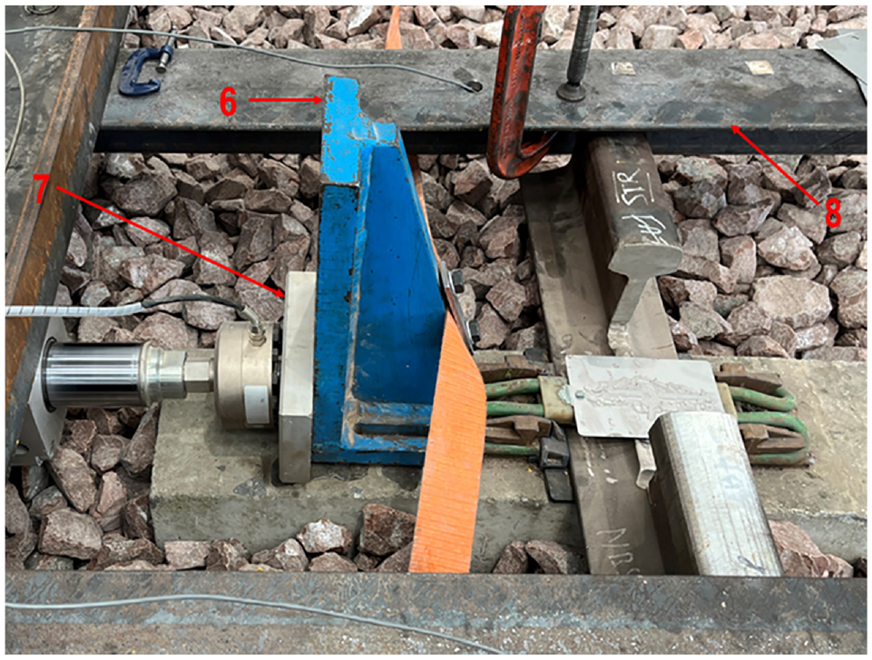
Wedge (6), actuator (7), and restraint (8) arrangement (copyright: Jacob Whittle and British Steel).
The Uplift Restraint
When developing SSPT methodology, a range of conditions limiting the uplift of the tested sleeper may be considered. Figure 5 shows a scale representing the reduction of uplift for a sleeper end rising because of lateral movement, ranging from complete freedom to uplift to full restraint of the sleeper. The former of these is the condition utilized by authors in previous SSPT investigations, where the sleeper was not restrained in the vertical direction. The opposite of this condition, on the right-hand side of the scale, is the fully restrained condition, which does not allow for any uplift of the sleeper. It is the view of the authors that both conditions are unrepresentative of the behavior of sleepers in track. A sleeper fastened to the rail as part of the larger track structure is not free to rise without the rail imparting a downward force opposing the vertical movement. However, the rail is not rigid, and its restraint is limited to the self-weight of the rail and sleepers, as these are usually not anchored to the underlying ground. Representing this in a laboratory test requires a flexible restraint system which partially restrains vertical sleeper movement, reducing uplift but not eliminating it entirely. The partially restrained condition specific to the test rig investigated here is shown in Figure 5 by the intermediate partially restrained condition, which limits the uplift from 20 mm to 15 mm during a steel sleeper lateral displacement of 60 mm.
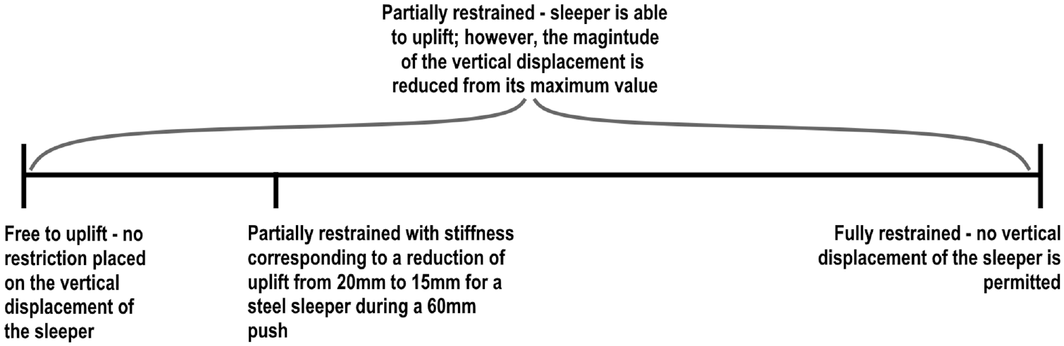
Scale representing the reduction of uplift for laterally displacing sleepers.
Preliminary tests conducted by the authors showed that sleepers tend to rotate, with only the trailing end of the sleeper experiencing uplift. Therefore, an uplift restraint (item 8) was designed to limit vertical displacements of the trailing end of the sleeper during testing. It is important to note that the restraint is not designed to exert initial vertical loads on the sleeper, for example, of the type which may be seen when investigating the influence of vehicle weight. Rather, the load exerted by the restraint is always a reaction force to an uplift of the sleeper, starting at a zero value when no uplift is experienced by the sleeper.
Defining the track conditions represented by the restraint involves a consideration of the source of loading that causes the sleeper to uplift as well as the effects of both the rail and the sleepers neighboring the sleeper of interest. For the work presented here, the uplift is assumed to be a function of the lateral displacement of the sleeper caused by a track buckle. The vertical forces exerted on the sleeper from the rail may be separated into three components. The first of these is the weight of the rail supported by the sleeper, which is dependent on the length of rail displaced upwards. A second component is the downward elastic restorative force caused by the rail deflecting. The final, third, component is the effect of the neighboring sleepers, which, during a buckle, would offer uplift forces either side of the sleeper of interest. Figure 6 shows these effects for a sleeper and rail section on the right and their counterparts for the uplift restraint during the SSPT on the left.
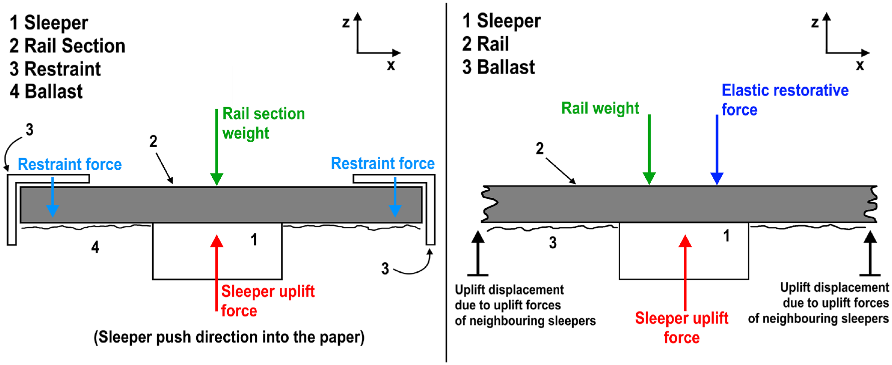
Diagram of the vertical forces on a section of rail during an single sleeper push test (SSPT) (left) representing the effects of the rail on an uplifting sleeper in service (right).
As can be seen, for the SSPT, the weight of the rail is accounted for by using a rail section fastened to the sleeper equivalent to the weight supported by a single sleeper in a track with 650-mm sleeper spacing, as specified in the BS 500:2000 test procedure ( 10 ) and the category 1 track specification in NR/L2/TRK/2102 ( 21 ). The uplift restraint is therefore a representation of the combined effect of the force caused by rail bending, the influence from neighboring sleepers, and any additional rail weight resulting from more than one sleeper uplifting. Although the extent that the rail in track reduces the uplift of sleepers during a buckle has not been investigated in the literature, an intermediate value has been chosen here. This provides a comparison against the free-to-uplift condition to study the effect restraining uplift has on lateral resistance. The restraint was designed to reduce the uplift of the sleeper during the SSPT such that, when a steel sleeper is pushed 60 mm, the magnitude of the uplift of the trailing end of the sleeper is reduced from 20 mm to 15 mm. To achieve this, two right-angle S275 steel sections of length several times that of the maximum push length were secured to the frame supporting the actuator, to interface with the head of the rail. Figure 7 shows the configuration of these beams and their proximity to the rail–sleeper assembly.
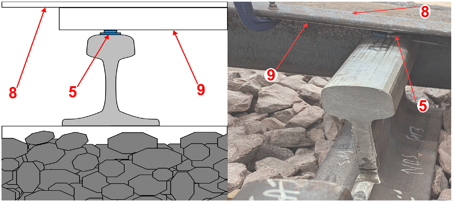
Diagram and photo of the restraint, including the restraint (item 8), uplift load cell (item 5), and shims (item 9) (copyright: Iwo Słodczyk and British Steel).
For both ends of the rail section, in-between the head of the rail and the restraint, a load cell was installed to measure the vertical force exerted by the restraint on the rail head. Thin shims were used to pack the space between the top of the load cells and the restraint to ensure initial contact. While this introduced an initial downward force on the sleeper, its magnitude was small (maximally one-tenth of the measured uplift forces) in comparison with the uplift forces measured during the test. To minimize the frictional resistance of the load cells interacting with the restraint, the contact between the top of the cells and the shims was lubricated. Furthermore, to account for the remaining friction in the contact, the coefficient of friction of the load cells sliding past the shims was determined experimentally before sleeper testing. The average coefficient of friction between one load cell and the restraint, under test conditions, was measured as 0.160 across six tests.
Following the SSPT using the uplift restraint, the behavior of the sleeper without the effect of the restraint was quantified. This was done by removing the beams, shims, and load cells measuring the uplift force, in place of which an LVDT was installed at the trailing end of the sleeper to measure the uplift displacement of the sleeper end. The test was limited to a shorter push distance because of the danger of impact between the rising sleeper end and the actuator arm.
Test Procedure and Program
Concrete and steel sleepers (as described in the “Single Sleeper Push Tests” section) were tested, two restraint conditions were considered, and for each test three repeats were performed, achieving a total of 12 tests. These are summarized in Table 1. Each SSPT followed a strict procedure: (i) First, the sleeper was positioned in the box and the ballast was formed co-planar with the sleeper top. (ii) The ballast around and underneath the sleeper was agitated using a Robel hand tamper and, in the case of the steel sleeper, ballast was manually pushed up into the hollow section of the sleeper. This was done to reduce voiding around and beneath the sleepers and to meet the manufacturer’s installation specifications ( 22 ). The ballast was not compacted beyond manually pushing the ballast to eliminate voids and ensuring contact with the sides and the leading face of the sleeper. (iii) The sleeper was pushed toward the ballast shoulder using the actuator, recording the displacement of the sleeper and the force exerted on the load cell on the head of the actuator. The sleeper was displaced at a constant rate of 10 mm/min up to 60 mm for restrained and 40 mm for unrestrained conditions by applying a load on the clip fastened to the trailing end of the sleeper through a wedge, as shown in Figure 4. All force and position data were acquired at a frequency of 10 Hz. (iv) Following testing, the actuator and sleeper were returned to their initial positions and the steps were repeated, starting from (ii). It should be noted that while all the ballast in the box was not replaced between tests, the ballast around and underneath the sleeper was agitated using a tamper to ensure the ballast condition for each test was as near as possible to that in previous tests.
Series of Tests Conducted Using the Sleeper Testing Rig
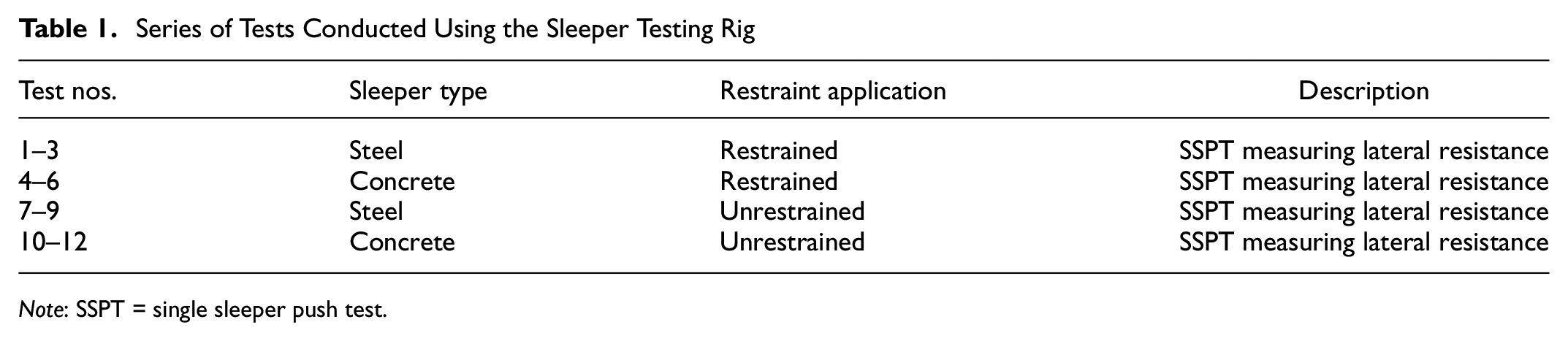
Note: SSPT = single sleeper push test.
Influence of Restrained Sleeper Lateral Resistance on Buckling Safety
The lateral resistance of sleepers in ballast is a key property when predicting the buckling safety of track (
1
). It influences the minimum buckling temperature increase (
To investigate the influence of lateral resistance on the property
To determine the temperature increase

where


and

for which
The general expression for the lateral displacement of the track (
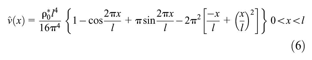
where

For the above formulas, the lateral resistance of sleepers in ballast

To calculate the
where, in the original model, a simplified expression for

As with


The value of

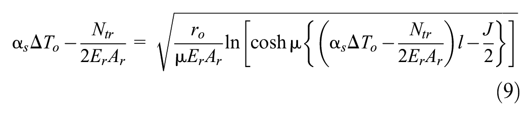
By substituting the expression for
The final step in implementing a variable lateral resistance in the buckling model was to define the function
The track parameters utilized in Equations 1–13 were as follows:


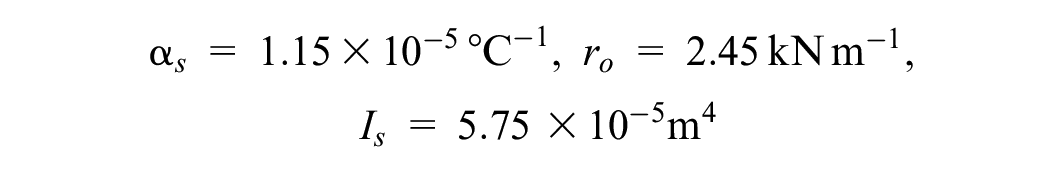
where
Results
To better understand the differences between the SSPT lateral resistance results and the behavior of sleepers in track, the uplift of sleepers has been examined from three different perspectives. Firstly, the magnitude of vertical displacement and the uplift forces when restrained were investigated. Secondly, the difference in lateral resistance between sleepers free to uplift and ones restrained using the partial restraint was examined. Finally, the effects of restrained and free-to-uplift lateral resistance on the buckling stability of track were considered. The sections below present the results of tests 1–12 (see Table 1) performed as described in the “Single Sleeper Push Tests” section. The uplift results are shown first, displaying the upward displacement of the sleepers and the force they exert on the restraint when it is utilized. The lateral resistance of the sleepers during the pushes is presented in the section following, with the restrained and unrestrained results shown first for concrete then for steel sleepers. The last section details the influence of the lateral resistance values on the buckling stability as well as the effect of assuming constant lateral resistance based on different values of SSPT push distance within the Grissom and Kerr model ( 23 ). A comprehensive record of the results presented throughout this section can be found in the Supplementary Material.
Uplift of Sleepers During SSPTs
Figure 8 shows the vertical displacement profiles for tests 7, 9, 11, and 12, which feature both sleeper types and were completed to BS 500:2000 ( 10 ) without a restraint. Tests 8 and 10 have been omitted owing to measurement device failure during the test; meanwhile, the results for test 9 are limited to a maximum lateral displacement of 48.2 mm, at which point the test was stopped to protect the actuator from collision with the rising sleeper end. Despite these limitations, the tests show a reasonable level of consistency for each of the different sleeper types. For concrete, the linear averaged gradient is 0.0933, in contrast with the much greater steel gradient of 0.376. The maximum values of uplift reached for steel and concrete sleepers are 20.9 mm and 6.72 mm, respectively.
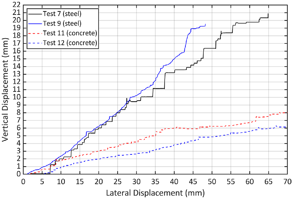
Uplift of the trailing ends of steel (solid line) and concrete (dashed line) sleepers without restraint.
In tests 1–6, three SSPTs were performed for each sleeper type with the restraint in place and the uplift loads recorded by the load cells (item 5). Figure 9 shows the change in the uplift load on the vertical axis, with the horizontal axis describing the movement of the sleeper toward the shoulder. As with the uplift displacements, the uplift loads increase with increasing lateral displacements for both types of sleeper. In agreement with the Figure 8 results, the steel sleeper produces significant uplift loads with a steep gradient. The uplift loads for concrete are much lower and show an initial incline which levels off in the region of 15–30 mm.
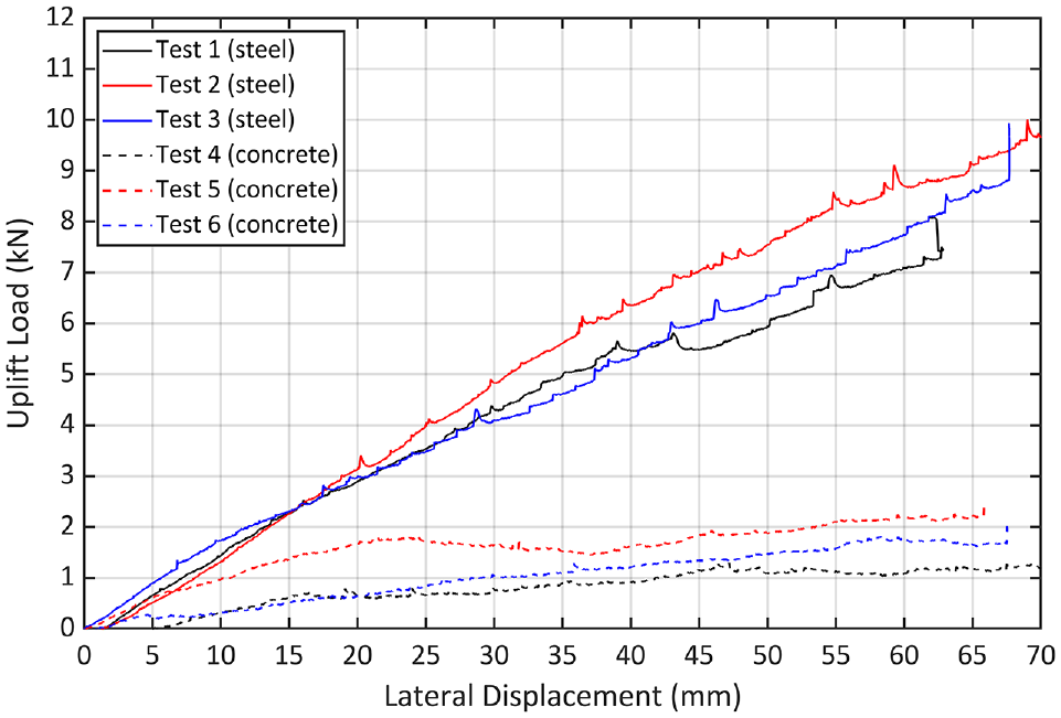
Uplift loads of steel (solid line) and concrete (dashed line) sleepers.
The presence of uplift can be seen (Figure 8) for both sleeper types beyond a 5-mm lateral displacement of the sleepers. The magnitude of the vertical displacement rises with lateral displacement and is substantial—greater than the downward displacement of the rail under train load ( 24 , 25 ). Additionally, the magnitude of uplift would be significant enough to affect the interaction of sleepers with ballast, reducing the effect of the bottom friction of sleepers during the test (see Figure 1).
Lateral Resistance Values
Lateral resistance values for tests 1–12 can be seen in Figures 10 and 11, with the restrained and unrestrained lateral resistance values shown in each figure for concrete and steel SSPTs, respectively. For these tests, the maximum displacement of the sleeper was limited to 40 mm, beyond which the unrestrained uplift posed a danger of impact between the sleeper and the actuator.
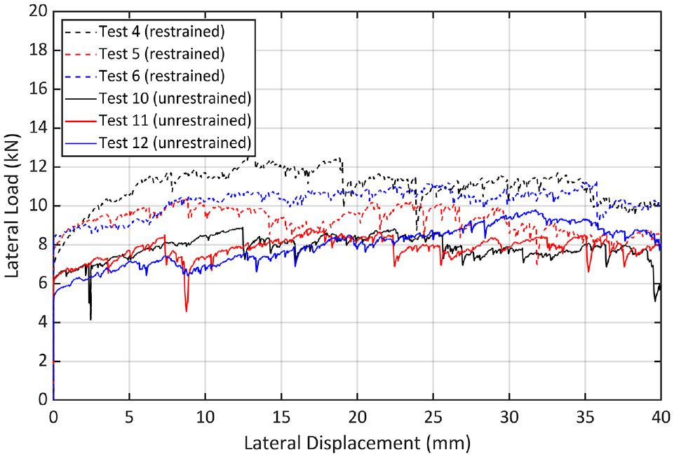
Lateral resistance of concrete sleepers with (dashed line) and without (solid line) the restraint.
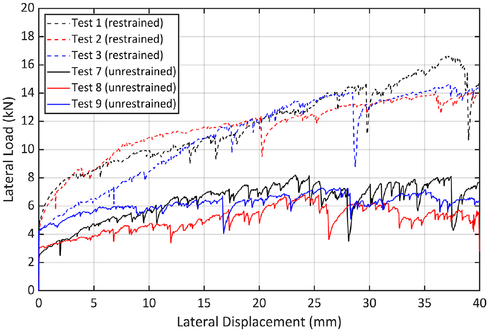
Lateral resistance of steel sleepers with (dashed line) and without (solid line) the restraint.
Figure 10 shows the lateral resistance results for the concrete sleepers tested, corrected for the frictional load, which was generated as the product of the coefficient of friction and the uplift force. The unrestrained tests show a characteristic shape of an initially high peak value followed by a region of constant lateral resistance which does not change significantly with sleeper displacement beyond 5 mm. The values recorded are broadly in agreement with the lateral resistance values of concrete sleepers investigated by other authors, including Zakeri et al. ( 26 ) and Le Pen and Powrie ( 5 ), as noted in Table 2. When the restraint was introduced, both the initial and the following steady lateral resistance value increased. The general shape of the lateral resistance curve also remained largely the same, albeit with slight differences for test 4 and test 5, which show the lateral resistance achieving a peak value and then relaxing to a lower lateral resistance.
Lateral Resistance Values for Concrete and Steel Sleepers for a 2-mm Push Distance
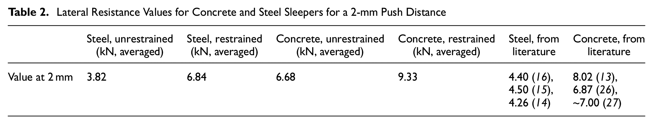
In contrast with the concrete sleeper, the steel sleeper results in Figure 11 show a significant difference between testing with and without the restraint. The lateral resistance curve generated by the unrestrained test achieves values of a lower magnitude compared with those of the concrete sleeper, with the values at small displacements being almost half those of concrete. The more realistic restrained steel test, on the other hand, generates lateral resistance values of a greater magnitude at every displacement point when compared with the unrestrained tests. Furthermore, the gradient of the lateral resistance increase in the region beyond 5 mm is also steeper when compared with the unrestrained condition. As with the concrete results, the steel sleeper results in Figure 11 were corrected for friction.
The lateral resistance values at 2 mm displacement for the unrestrained condition are in broad agreement with those reported by previous authors, as seen in Table 2, though a difference of up to about 17% lower in lateral resistance can be seen for values from this paper.
Buckling Safety
The Grissom and Kerr ( 23 ) buckling model was used to investigate the impact of the lateral resistance values presented in the “Lateral Resistance Values” section on the buckling stability of track. First, a function was estimated for the lateral resistance results, then buckling stability curves were calculated for each function with the other track parameter values as given in Equation 14. Finally, both the restrained-concrete and restrained-steel lateral resistance results were compared against buckling curves calculated using constant assumptions for a range of lateral resistance values.
Continuous Functions of Lateral Resistance
Figure 12 shows the recorded values of lateral resistance from tests 1–12 grouped by sleeper type and restraint condition into (a) unrestrained concrete, (b) restrained concrete, (c) unrestrained steel, and (d) restrained steel, with each grouping showing three tests and a function fitted to the data provided by the fit command in MATLAB.
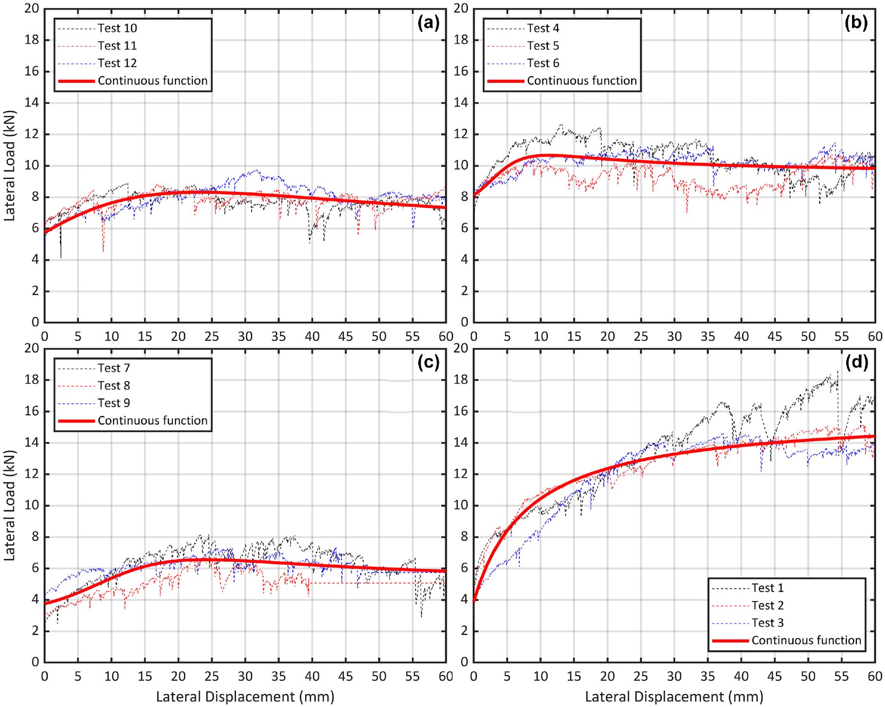
Lateral resistance results for (a) unrestrained concrete, (b) restrained concrete, (c) unrestrained steel, and (d) restrained steel, with a fitted function of continuous lateral resistance for each.
For each set of tests, the function approximates the recorded data and the assumed lateral resistance for large displacement values, assuming a constant lateral resistance beyond 60 mm equal to the value at 60 mm. For test 8, which was stopped early, a constant lateral resistance was assumed from the point of its greatest lateral displacement. Figure 12, a to c , exhibits similar characteristic curve shapes, albeit with different magnitudes of lateral resistance. In contrast, Figure 12d shows a different profile, with continually rising lateral resistance over the displacement range tested.
The following equations describe the fitted functions:
(a)

(b)

(c)

(d)

where
Impact on Buckling Stability
The equations for the fitted lateral resistance functions (Equations 15–18) were applied in the modified Grissom and Kerr buckling model to generate the post-buckling stability curves shown in Figure 13. A critical feature of these graphs is the minimum buckling temperature increase (
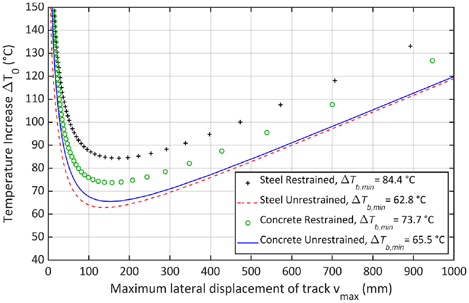
Buckling stability curves for the four functions of variable lateral resistance.
For the cases examined, the restrained tests predict higher
Influence of the Constant Lateral Resistance Function Assumption
Assumptions of constant lateral resistance, based on four values of sleeper lateral displacement
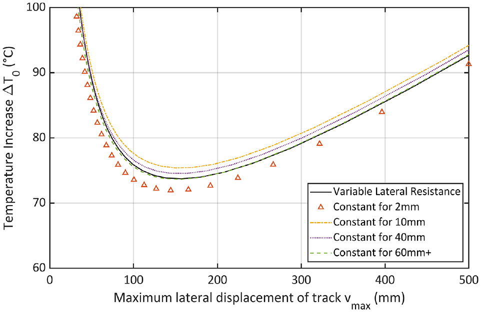
Buckling stability curves for the restrained concrete sleeper condition for variable and constant lateral resistance assumptions.
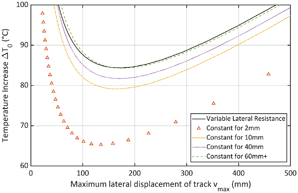
Buckling stability curves for the restrained steel sleeper condition for variable and constant lateral resistance assumptions.
When comparing Figures 14 and 15, a difference is seen in the grouping of the assumed constant lateral resistance curves versus that of the variable lateral resistance. For the concrete sleeper in Figure 14, each assumed constant value of the lateral resistance provides a buckling curve close to that given by the variable lateral resistance, with the greatest difference in
Discussion
The behavior of a concrete and a steel sleeper during push tests in a ballast box has been investigated in an effort to better understand their uplift, lateral resistance, and response to the presence of a vertical restraint. A difference in uplift behavior can be seen between the two types of sleepers, with steel sleepers experiencing much higher vertical displacements than their concrete counterparts. This difference in behavior could be the result of either or all of the following mechanisms. Firstly, the sleeperexperiences a moment due to the load exerted on it from the actuator. This load follows an axis above loads exerted on the sleeper in the opposite direction, in the same way as a lateral load imposed by a rail experiencing thermal expansion would apply a load above the sleeper. As Figure 1 shows, each of the three components of lateral resistance—the side (Rs), bottom (Rb), and end (Re) resistance—is below the axis of the fastener. Although their exact contributions in the tests here are not investigated, the resultant resistance force will have a nonzero offset below the sleeper top. This difference in loading axis between the ram force and the resultant resistance force will result in a moment dependent on the sleeper weight. Furthermore, a parallel can be drawn between the uplift loads in Figure 9 and the restrained lateral resistances in Figures 10 and 11 for the two sleeper types. For both uplift load and restrained lateral resistance, the steel sleeper sees a continual rise, while the concrete sleeper remains relatively level after it has risen to a peak value. Though this behavior is not directly mirrored between the graphs, there is a clear commonality in behavior between the uplift and the lateral load (and therefore the moment) exerted on the sleeper by the actuator during the push. On the other hand, the ratio of sleeper masses (accounting for rail weights equivalent to the length of rail supported by one sleeper) is 2.35, whereas the ratio of averaged sleeper uplifts is 3.2, which suggests that the sleeper uplift is not directly inversely proportional to the sleeper weight. While the moment exerted on the sleeper could be eliminated or reduced by pushing at a lower height, a push below the sleeper top would not be representative of the behavior of the sleeper during a buckle. The forces during track buckles originate from the rail and act on the sleeper via its fastening system, thus following an axis above the sleeper top to push the sleeper laterally. Therefore, sleeper uplift, restrained uplift loads, or a combination of both is expected to be present during a buckle.
When compared with lateral resistance values for steel and concrete sleepers in the literature (both in track and in laboratory conditions), both types of sleeper were found to provide similar albeit slightly lower values for the unrestrained condition tests. This may be the result of a lower ballast compaction typical of laboratory testing, though differences in the push height above the sleeper top or the shape of the shoulder could play a role. As such, the values reported here are most similar to the lower values of the two rightmost columns of Table 2. The increase in lateral resistance for the restrained condition of both sleepers could be attributed to changes in the bottom friction component, which increases with the greater level of maintained contact associated with lower uplift. If this contact was not lost because of uplift, for example in the case of the steel sleeper spade end scooping ballast, an increased pressure downwards from the restraint (and so the rail) would be created, leading to greater friction forces. For the concrete sleeper, this effect could explain why the lateral resistance is increased at all points while maintaining a largely similar shape; however, this is not the case for the steel sleeper. The shape of the steel sleeper is hollow and it features angled ends (see Figure 2), which could lead to a different interaction with the ballast compared with the concrete sleeper. As the trailing end is pushed against the sloped ballast inside of the steel sleeper, a component of the resultant normal force acts in the upwards (z) direction. The sleeper could then “ride” over the ballast if the friction between the inside of the sleeper and the ballast particles makes it easier to slip past the ballast than to push through it. This interaction is altered with the presence of the uplift restraint, which, by reducing the upward displacement of the sleeper end, results in a greater area of contact inside of the sleeper. This results in the inside face of the trailing end creating a second zone of the end pressure demonstrated in Figure 1. Furthermore, reducing uplift ensures that more ballast remains inside the sleeper and is therefore able to generate a greater internal friction for the side walls.
For both concrete and steel sleepers, the restrained condition provided greater lateral resistance and a resulting higher minimum buckling temperature in Figure 13, with the highest
The results seen in Figure 14 help to validate the lateral resistance investigations of previous authors who considered the lateral resistance of concrete sleepers for a lateral displacement of up to 2 mm. While greater push distances may help us to understand the lateral resistance profile of concrete sleepers, an assumption of 2 mm is acceptable for the purposes of calculating the minimum buckling temperature. By extension, this also partially validates the assumption of constant lateral resistance beyond 60 mm, which was used when fitting the lateral resistance functions seen in Figure 12. However, as Figure 15 shows, assumptions of constant lateral resistance from small displacement values are not equally valid for steel sleepers. When the steel sleeper is restrained, its lateral resistance continues to develop at a significant rate up to the 60-mm push distance and does not level off to a steady value. Furthermore, the constant for 60 mm+ line is seen to more closely resemble the buckling curve of the variable lateral resistance than assumptions based on the smaller displacement values. This finding supports the observation expressed by Kish and Samavedam ( 1 ), where a constant lateral resistance assumption introduced significant error into the buckling response compared with a nonlinear resistance. Furthermore, several authors, including Lim et al. ( 28 ) and Miri et al. ( 29 ), have considered initial track misalignment magnitudes of up to 40 mm, for which a non-progressive buckling curve was seen. This would suggest that for buckling models, the lateral resistance of sleepers needs to be expressed for push distances up to at least 40 mm to fully capture the influence on the buckling curve.
The above observations suggest that the uplift of sleepers needs to be considered when investigating the lateral resistance of sleepers. Reducing uplift has a significant impact on lateral resistance, which in turn greatly influences the calculated buckling stability of track. This effect is particularly pronounced for steel sleepers, which see a large difference in their lateral resistance profile. Finally, a 2-mm push distance is seen to be acceptable to capture the constant lateral resistance of concrete sleepers. However, this assumption is not seen to hold true for steel sleepers, which are seen to require greater push distances to fully characterize their lateral resistance profile.
Conclusion
The uplift behavior of steel and concrete sleepers has been investigated by using a single sleeper push test (SSPT) in a ballast box and considering the lateral resistance when the sleepers were free to rise and the lateral resistance when their vertical displacement was partially restrained. The uplift magnitudes of the sleepers when not restrained were recorded, and measurements of the lateral load and sleeper lateral displacement were taken to establish the lateral resistance of both sleeper types for both restraint conditions. It was found that the standard SSPT methodology generates uplift for both steel and concrete sleeper types which is particularly pronounced for large displacements. When this uplift was partially restrained, a significant difference in recorded lateral resistance values was seen, with the restrained tests generating lateral resistance of a greater magnitude. This effect was especially prominent for steel sleepers, which saw greatly increased lateral resistance values which continued to rise throughout the full length of the push. The influence of uplift on buckling stability curves was explored, and it was found that when sleepers were free to uplift, the resulting minimum buckling temperatures were significantly lower than when the sleepers were restrained. It can be concluded that uplift of sleepers has a substantial influence on both the lateral resistance of sleepers and the buckling stability of track and needs to be carefully considered when designing lateral resistance tests. A further finding showed that, for concrete sleeper lateral resistance, a 2-mm push distance was representative of the full variable lateral resistance for the purposes of calculating buckling stability. However, for steel sleepers, much greater push distances are required to fully capture their lateral resistance behavior. These observations enhance the understanding of the differences between SSPT lateral resistance and the lateral resistance of sleepers in track. With a better understanding of how rail in track restrains sleeper uplift, an improved SSPT methodology can be developed which more accurately represents the lateral resistance in track, leading to better predictions of buckling stability.
Footnotes
Acknowledgements
The authors would like to thank Scott Dyball and Andy Trowsdale at British Steel Limited for their assistance in completing this work.
Author Contributions
The authors confirm contribution to the paper as follows: study conception and design: I A Słodczyk, J W Whittle, D I Fletcher, S Danks; data collection: I A Słodczyk, J W Whittle, S Danks; analysis and interpretation of results: I A Słodczyk, J W Whittle; draft manuscript preparation: I A Słodczyk, J W Whittle. All authors reviewed the results and approved the final version of the manuscript.
Declaration of Conflicting Interests
The author(s) declared no potential conflicts of interest with respect to the research, authorship, and/or publication of this article.
Funding
The author(s) disclosed receipt of the following financial support for the research, authorship, and/or publication of this article: The authors would like to thank the Engineering and Physical Sciences Research Council (EPSRC; grant ref. EP/T517835/1), the EPSRC through the Advanced Metallic Systems Centre for Doctoral Training (EPSRC grant ref. EP/S022635/1), Network Rail, and British Steel Limited for providing the funding for this research.
Supplementary Material
For the purposes of open access, the author has applied a Creative Commons Attribution (CC BY) license to any author-accepted manuscript version arising from this submission.