
Abstract
This paper presents the development and crash testing of a new surface-mounted median guardrail for use on concrete pavements or bridge decks. The research team developed several preliminary design concepts of the median guardrail. Of these, one was selected for further development through component-level testing, simulation analysis, and full-scale crash testing. The researchers constructed a test installation of the new surface-mounted median guardrail and performed Manual for Roadside Assessing Safety Hardware (MASH) Test Level 3 testing, which involves performing Test 3-10 with a small passenger car and Test 3-11 with a pickup truck. In both tests, the surface-mounted median guardrail successfully contained and redirected the vehicle. The guardrail design passed the MASH evaluation criteria for both tests. The new surface-mounted median guardrail is ready for implementation by user agencies. It could be a good alternative to the much heavier concrete median barriers on bridges where reducing bridge loads is an important consideration and there is room to allow some deflection of the guardrail. Furthermore, because of a lack of median guardrails for use on concrete pavements, the new surface-mounted median guardrail could be a good cost-effective alternative to concrete median barriers placed on concrete pavements.
Keywords
Median barriers are commonly used between opposing lanes of traffic to prevent vehicles from one side of the road from encroaching on the opposite side and causing crossover crashes. Concrete barriers and metal-beam guardrails are the most common types of median barriers. Currently available metal-beam median guardrails require posts that are installed in soil. For this reason, they cannot be used on concrete pavements or bridge decks. In these situations, concrete median barriers are commonly used.
Concrete median barriers are generally very effective in preventing crossover crashes and require minimal maintenance over the lifecycle. However, they are significantly heavier than metal-beam guardrails and have a much higher initial cost. In many bridge applications, especially those that have thin decks, it is desirable to reduce the weight supported by the bridge. A metal-beam median guardrail that can be bolted onto the concrete deck can significantly reduce the weight supported by the deck.
Furthermore, for lower average daily traffic (ADT) applications, and where the site conditions allow for slightly greater median barrier deflection, a metal-beam median guardrail system has the potential of being more cost-effective than a concrete median barrier. In areas that receive a great deal of snow or rain/flood water, a metal-beam median guardrail system also has the potential for reducing snow accumulation and increasing water flow compared to concrete median barriers. Having a successfully crash-tested metal-beam median guardrail system that can be installed on concrete pavements and bridge decks will allow user agencies to extend the benefits of using a median guardrail on more sites where currently only concrete median barriers can be used.
This paper presents the design development and crash test evaluation of a new surface-mounted metal-beam median guardrail that can be installed on concrete pavement and bridge decks.
Previous Work
In developing preliminary concepts of the new surface-mounted metal-beam guardrail, the researchers relied on some of the past research described here. In 1978, Hirsch et al. ( 1 ) designed and crash tested a surface-mounted bridge rail that comprised a tubular rail section supported by W150 × 14 steel posts that were welded on a baseplates. The baseplates were bolted to the underlying concrete deck with anchor bolts (see Figure 1). The tubular section comprised two W-beam guardrail sections that faced away from each other and were welded together at the top edges. This surface-mounted bridge rail was successfully crash tested under NCHRP Report 230 criteria ( 2 ).
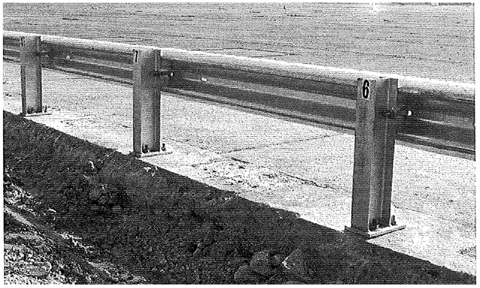
Surface mounted strong post bridge rail system.
At a later stage, the system was crash tested to NCHRP Report 350 criteria but failed to pass Test 3-11 because of the vehicle rolling on its side ( 3 , 4 ). The system was able to contain and redirect the vehicle; however, some of the anchor bolts pulled out of the concrete, which allowed the baseplates to move and resulted in high vehicle roll. There were several redesign efforts made at the time by allowing the post to disconnect from the base plates instead of the anchor bolts pulling out of the concrete or the post flanges rupturing. A couple of reduced weld patterns between the post and baseplate were evaluated through component-level testing and subsequently used in full-scale crash testing. However, the redesign efforts were not successful in achieving an NCHRP Report 350 compliant design. The design of the weld patterns to achieve controlled and timely release of the post from the baseplate proved difficult.
In 2016, Williams et al. ( 5 ) developed the design of a weak-post bridge rail that was surface mounted. This design comprised a W-beam rail supported by S3 × 5.7 posts that were welded on baseplates, which were bolted on a concrete deck with an epoxy anchor (see Figure 2). The posts were spaced at a half-post spacing of 37.5 in. This bridge rail system passed the America Association of State Highway and Transportation Officials (AASHTO) Manual for Roadside Assessing Safety Hardware (MASH) Test Level 3 (TL-3) ( 6 ).
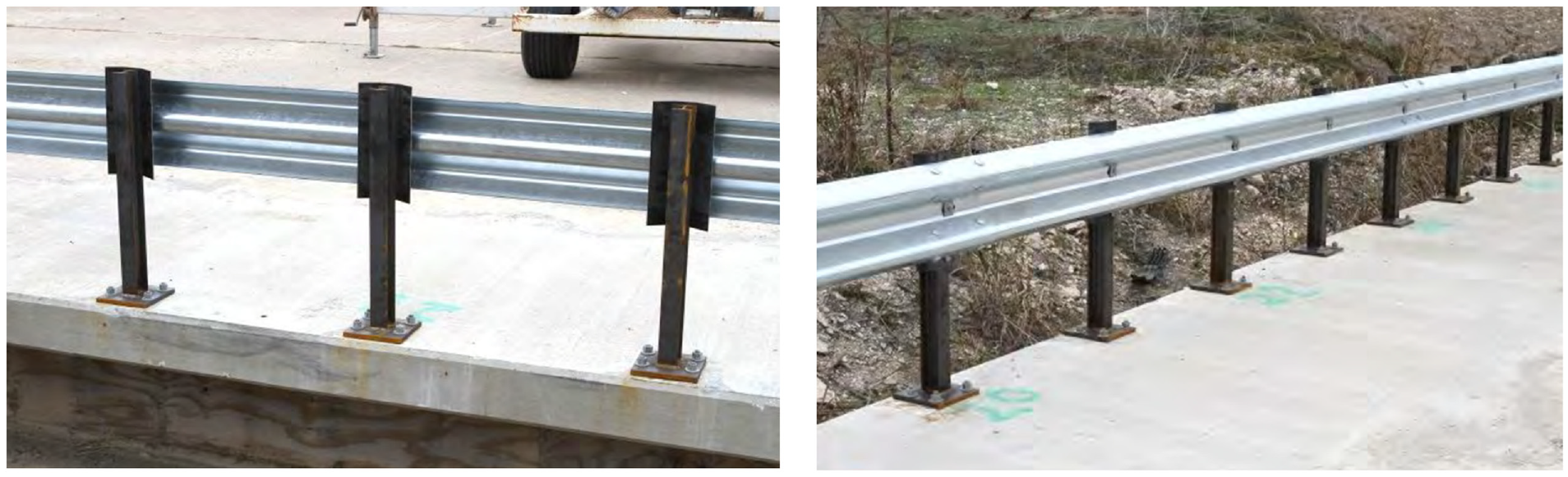
Surface mounted weak post bridge rail system.
In 2014, Abu-Odeh et al. ( 7 ) developed the design of a W-beam guardrail with standard W6×9 steel posts that were spaced 75 in. apart and were installed in soil (see Figure 3). Each side of the median guardrail had a 12-gauge standard W-beam rail. Both rail sections were attached to the same posts, each separated by 8-in.-deep wood blocks. The top of the rail was at a height of 31 in. The system was successfully crash tested for MASH TL-3.
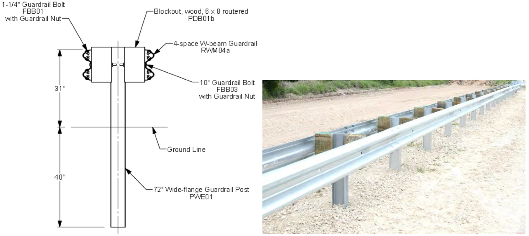
W-beam median barrier with posts installed in soil.
Conceptual Design
In developing the design concepts for the surface-mounted median guardrail, the researchers focused primarily on designing a system that could be directly bolted on existing concrete pavement or deck, without the need for cast-in sockets. Among the existing median barriers, high-tension cable barriers can also be used if their posts are bolted to the concrete surface. However, cable barriers typically have higher deflection than that desired for this research and were therefore not considered.
The researchers developed three preliminary design concepts, as shown in Figures 4 and 5. Two of the concepts (Concepts A and B) were based on the 31-in.-tall W-beam median barrier system with posts installed in soil (Figure 4) ( 7 ). In both concepts, the guardrail post was attached to a baseplate that was bolted to the underlying concrete with epoxy anchors. Both concepts used W6×9 steel posts that were spaced 75 in. apart. A W-beam guardrail section was attached on each side of the post, spaced by 8-in.-deep wood blocks.
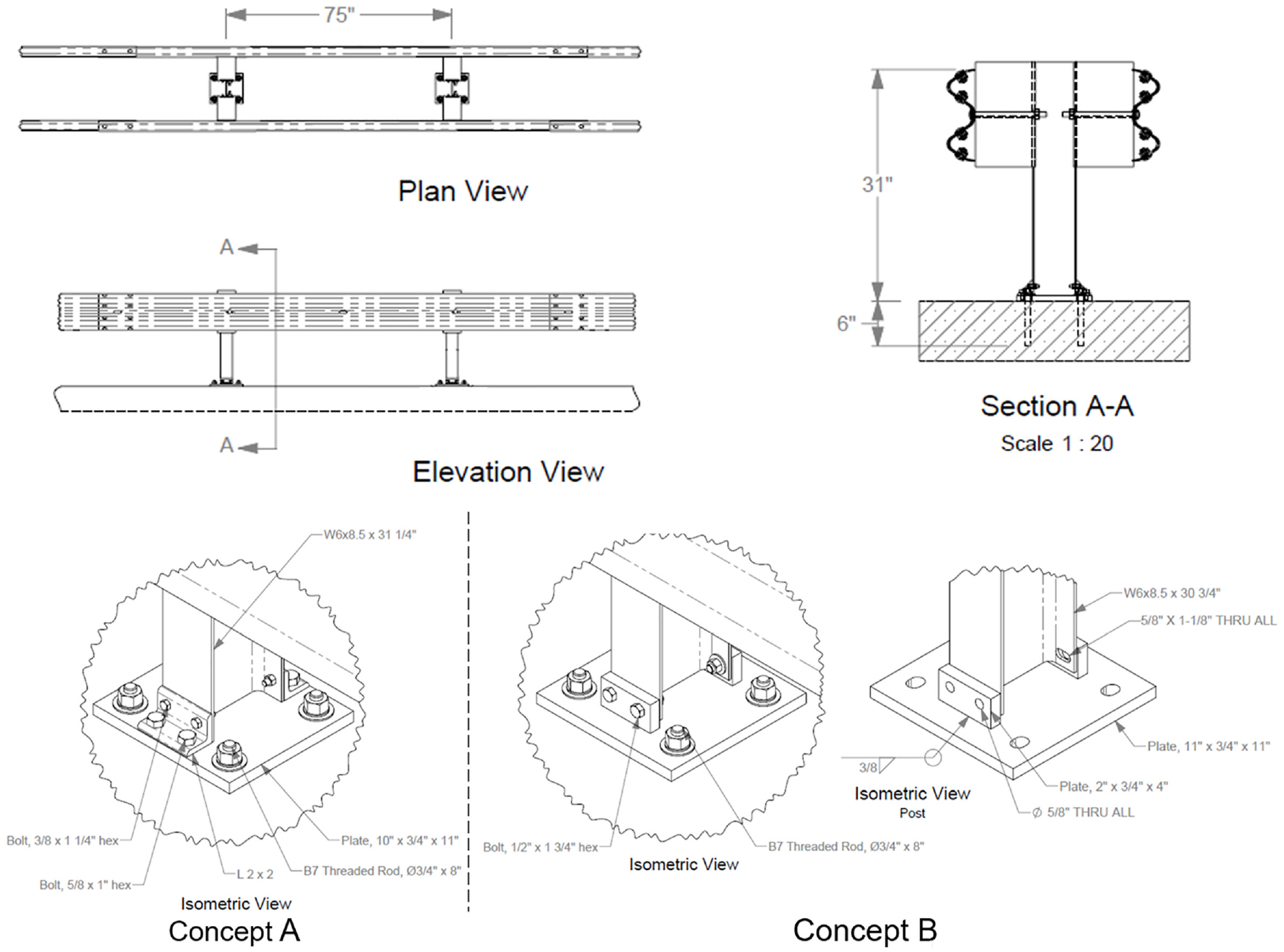
Concepts A and B of the surface mounted median guardrail.
Concept C of the weak-post surface mounted median guardrail.
In Concept A, the post-to-baseplate connection used angles bolted on the baseplate, and shear bolts were used to attach the post to these angles. The shear bolts were designed to fail to release the post from the baseplate. The advantage of this concept was that the baseplate and angles would be mostly reusable after impact. Only shear bolts would need to be replaced. The challenge with this concept would have been to determine suitable shear bolt and angle sizes for timely and controlled detachment of the post from the baseplate. Another drawback of this method would have been that the baseplates needed threaded holes for connecting the angles.
In Concept B, the flanges of the post had horizontal slots at the bottom. Connection to the baseplate was made by bolting flanges to stiff vertical tabs welded on the baseplate. The post was designed to release on impact by tearing the flanges at the slot locations. The baseplate and the stiff tabs were expected to be reusable after a vehicle impact. This concept did not require the threaded holes needed in Concept A. The challenge with this concept would have been sizing the slots that would allow controlled release of the post by tearing the flanges.
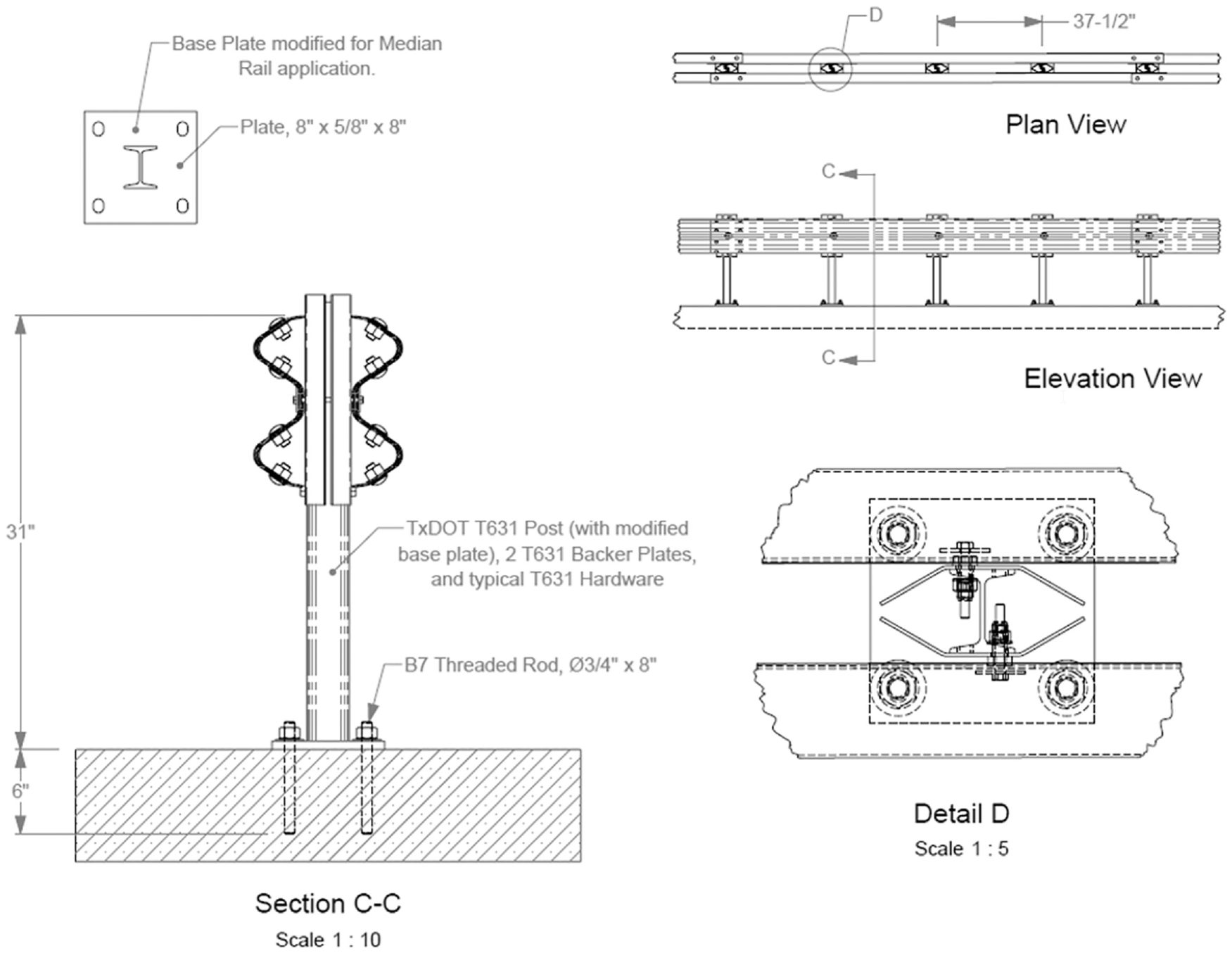
The third concept was based on weak-post surface-mounted bridge rail design (Figure 5) ( 5 ). In this concept, S3 × 5.7 weak posts were welded to an ASTM A36 baseplate that was attached to the underlying concrete with epoxy anchors. Half-post spacing of 37.5 in. was used. W-beam sections were attached on each side of the posts using shear bolts, without any blockouts. An ASTM A1008 11-gauge 15 in. × 8-in. bent backup plate was placed between the guardrail and post at each attachment location to shield the W-beam from the edge of the post flange, which can possibly lead to rail tear or rupture as the vehicle passes by during impact and redirection.
A disadvantage of this system would have been the need to replace more posts on vehicle impact. However, the main advantage of this design was that the roadside bridge rail version of this system had passed MASH testing, and thus the researchers had the highest confidence in the working of this concept. The design concept also did not rely of material failure of the welds or slots in the posts, which can have a great deal of variability and quality control issues in field installations. Furthermore, a successful design based on this concept would have allowed terminating the median guardrail by transitioning to the Midwest Guardrail System (MGS) W-beam guardrail and terminating with a MASH-compliant end terminal. Past research has shown that the half-post spacing of a weak-post system is roughly equivalent to the full-post spacing of the strong-post W-beam guardrail ( 8 ). Thus, the transition from the weak-post to the strong-post W-beam system could be achieved by simply changing to full-post spacing with the W6 × 8.5 posts. For the reasons described above, the weak-post median guardrail concept (Concept C) was selected for further design and development.
Component Testing
The researchers performed three component-level tests using surrogate bogie vehicle impacts to evaluate the weak-post guardrail design concept. Two tests were performed by impacting the weak-post and anchored baseplate assembly without any other parts installed. The tests were used to verify that the baseplate anchorage design was adequate and that epoxy anchors could be reused after an impact. A third test was performed with a short section of the surface-mounted rail system to determine the overall dynamic response of the short segment. The results of these tests were also used in developing the finite element (FE) model of the full guardrail system.
In all tests, the impacting bogie vehicle weighed 2130 lb and had a rigidized pipe nose. The three bogie impact tests performed were numbered 440521-01-B1, 440521-01-B2, and 440521-01-B3. The installation for Tests 440521-01-B1 and 440521-01-B2 consisted of two S3 × 5.7 × 313/8 posts welded onto an 8-in. × 5/8-in. × 8-in. baseplate (Figure 6). The posts were mounted to a concrete slab measuring 12 ft 6 in. wide, 45 ft long, and 8 in. deep. Figure 6 also shows the orientation of the post pairs with respect to the direction of bogie impact for Tests 440521-01-B1 and B2. The posts in Test 440521-01-B1 were impacted in the direction of the strong axis of the posts. In Test 440521-01-B2, the posts were rotated for an oblique impact. During an actual vehicle crash event, the redirecting vehicle does not strike the guardrail posts along the true strong or weak axis of the posts. Guardrail posts are known to rotate ahead of the approaching vehicle because of the defection of the guardrail, thus bending in lateral torsional buckling mode. The rotated orientation of the post pair in Test 440521-01-B2 was selected to be closer to this mode of post bending.
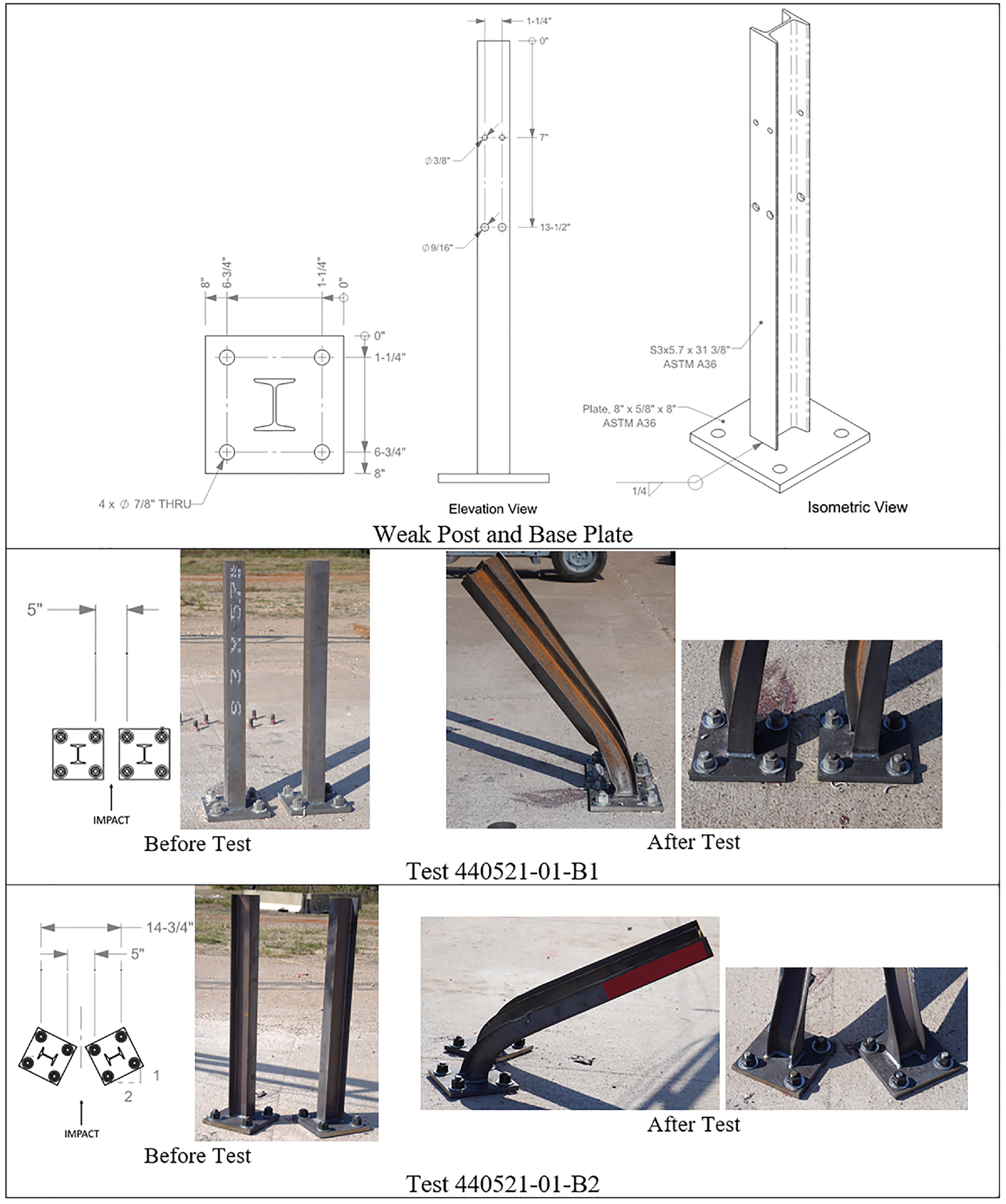
Bogie testing with post pairs.
The installation for Test 440521-01-B3 was a 25-ft section of W-beam median barrier mounted on the same post types and installed on the same concrete pavement. The baseplates were anchored to the concrete pavement using four 3/4-in. diameter B7 threaded rods that were each installed with an F844 washer, an F436 washer, and a heavy hex nut. The threaded rods were 8 in. long, of which 6 in. was embedded in concrete and secured with Hilti HIT-RE 500 V3 epoxy. The concrete slab was unreinforced. The specified minimum compressive strength of the concrete was 3500 pounds per square inch (psi). The actual compressive strength on the day of all three tests was 5070 psi.
In Test 440521-01-B1, the bogie vehicle impacted at the centerline of the post pair at an impact speed of 18.9 mph. The impact occurred at a height of 24.5 in. from the grade. Figure 6 shows the post installation before and after the test. Both posts were deformed at the base, but no damage to the anchors or the concrete pavement was noted. In Test 440521-01-B2, the bogie vehicle impacted at the centerline of the post pair at an impact speed of 20.8 mph. The impact occurred at a height of 22.5 in. from grade. Figure 6 shows the post installation before and after the test. Both posts were deformed at the base, but no damage to the anchors or the concrete pavement was noted.
In Test 440521-01-B3, the bogie vehicle impacted the center of a 25-ft long span of the median guardrail section at an impact speed of 21.4 mph and an impact angle of 90 degrees. The impact occurred at a height of 22.6 in. from the grade. Figure 7 shows the test installation before and after the test. The bogie vehicle came to a stop after impact and then rebounded. The welds of the posts at the baseplate did not fail. There was also no damage to the anchors or the concrete pavement at the baseplate locations. More details about the test installation and component testing can be found in the project report ( 9 ).
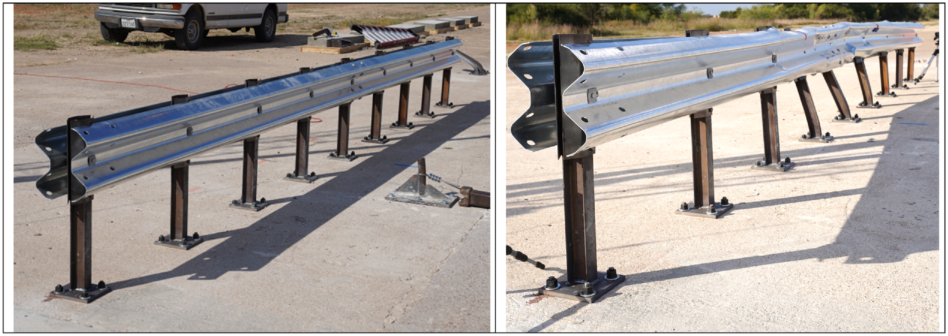
Bogie test 440521-01-B3 of a 25-ft long segment of weak-post median guardrail system.
Design Analysis
After the component testing, the researchers developed a FE model of the surface-mounted median guardrail system and performed impact simulations with MASH TL-3 impact conditions. Presented here is an abbreviated summary of the simulation analysis. Further details can be found in the research report ( 9 ).
All FE simulations were performed using LS-DYNA, which is a commercially available general-purpose FE analysis software. The researchers first developed a FE model of the post and baseplate and performed simulations of the component-level bogie impact tests described earlier. The goal of these simulations was to verify that the post and baseplate model adequately captures the post deflection response observed in the bogie impact tests. Figure 8 shows a comparison of the simulation results of the post pair deflection versus time for Tests 440521-01-B1 and B2. The results show that the post and baseplate model adequately captured the post deflection response observed in both tests.
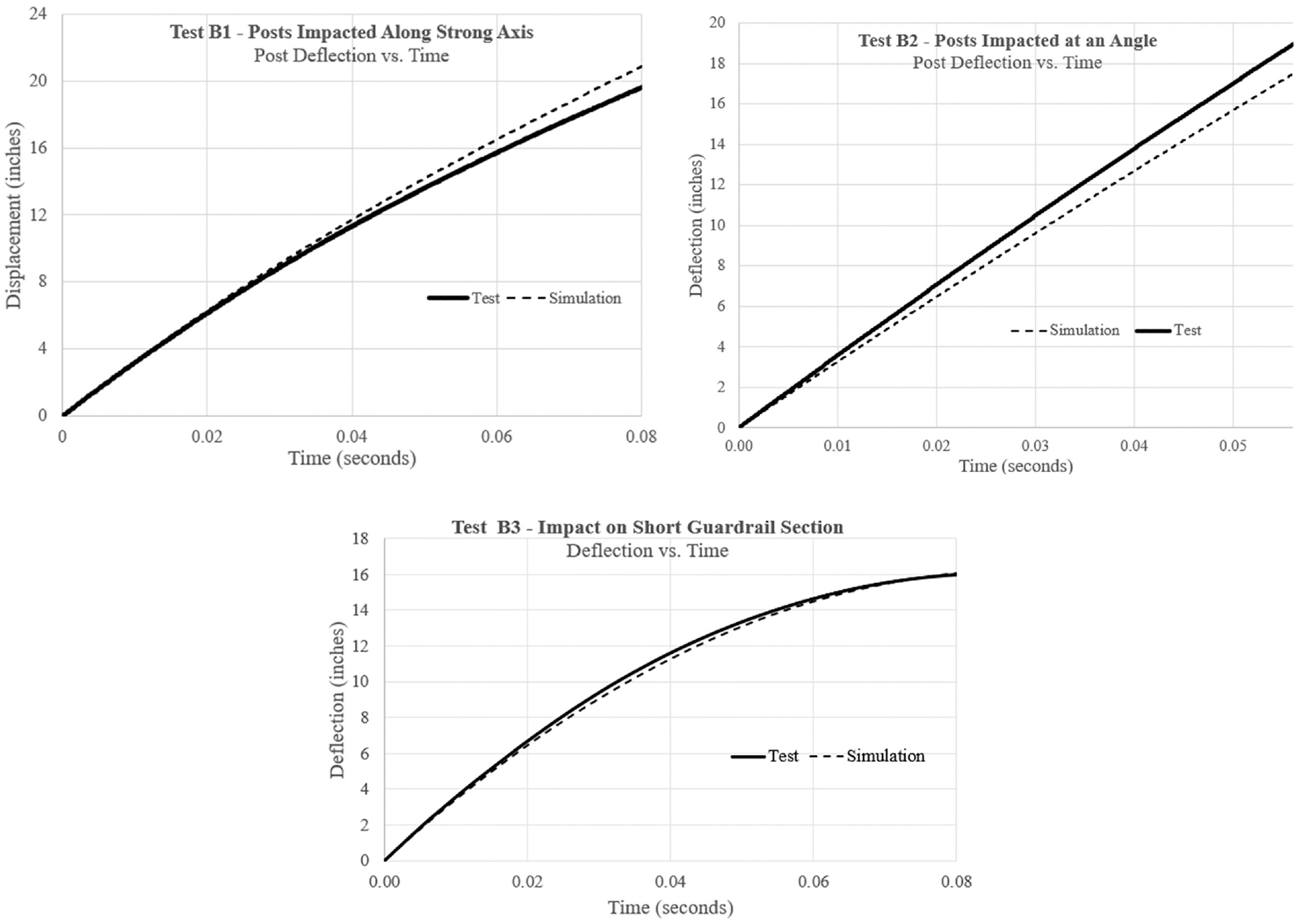
Comparison of test and simulation deflection–time response for bogie tests.
The researchers then developed a model of the short guardrail section of Test 440521-01-B3 and incorporated the validated post and baseplate model. Figure 8 shows the comparison of the guardrail deflection as a function of time between the bogie test and the simulation. Figure 9 also shows the deflected state of the guardrail section after the bogie impact in the test and simulation. The results showed that the simulation model adequately captured the impact response determined in the crash test. Following this, the researchers extended the model to a full-scale guardrail system for vehicle impact simulations.
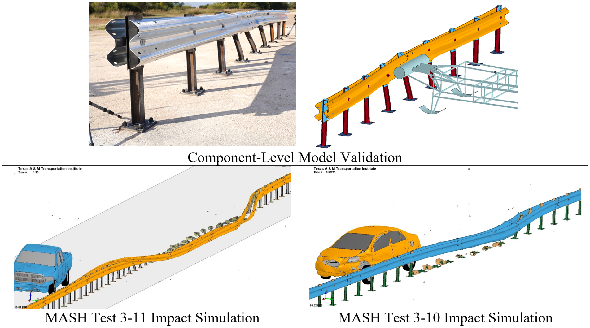
Results of dynamic impact simulations of short and full-system models.
The researchers performed the impact simulation of MASH Test 3-11 with a Dodge Ram pickup truck model (5000-lb vehicle impact at 62 mph speed and 25-degree angle). The vehicle was successfully contained and redirected, as shown in Figure 9. The researchers also performed the impact simulation for MASH Test 3-10 with a Toyota Yaris small car model (2420-lb vehicle impact at 62 mph speed and 25-degree angle). The vehicle was successfully contained and redirected, as shown in Figure 9. Based on the successful performance of the guardrail in impact simulations of MASH Tests 3-10 and 3-11, the researchers proceeded with full-system crash testing.
Full-Scale Crash Testing
Test Installation Details
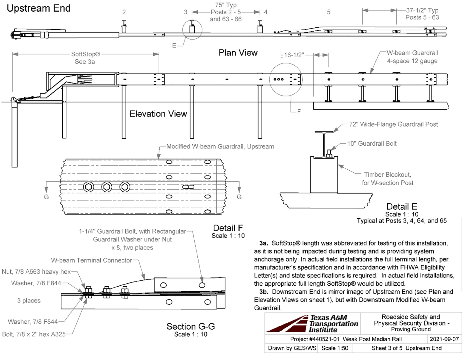
The test installation consisted of a weak-post, median W-beam guardrail system spanning 187 ft-71/4 in. (posts 5–63) before transitioning to a single-sided standard strong-post W-beam guardrail system and a guardrail end terminal (posts 1–4 and 64–67) on each end of the installation (Figures 10–12). The total length of the installation was 239 ft-5 in.. The posts of the median guardrail comprised S3 × 5.7 steel welded to baseplate plates measuring 8 in. × 8 in. × 5/8 in. thick. The posts were spaced evenly at 37 1/2 in. and were mounted onto an unreinforced 8-in.-thick concrete slab using Hilti HIT-RE500 V3 epoxy anchors. The concrete slab extended for 184 ft-0 in. onto which the 59 posts for the weak-post median guardrail were secured. Two standard W-beam rail elements were attached on each side of the S3 × 5.7 posts. An ASTM A1008 11-gauge, 15 in. × 8-in. bent backer plate was placed between the post and the W-beam rail element on each side, except for the posts at the rail splice locations. The backer plate was placed to shield the 12-gauge W-beam guardrail from interacting with the edges of the posts, which are known to initiate a tear in the rail, resulting in rail rupture. At a splice location, however, since two W-beam sections overlap each other, the backer plate was not considered necessary. The rail and the backer plate were connected to the post using a 5/16-in. diameter A307 bolt, as shown in Figure 10.
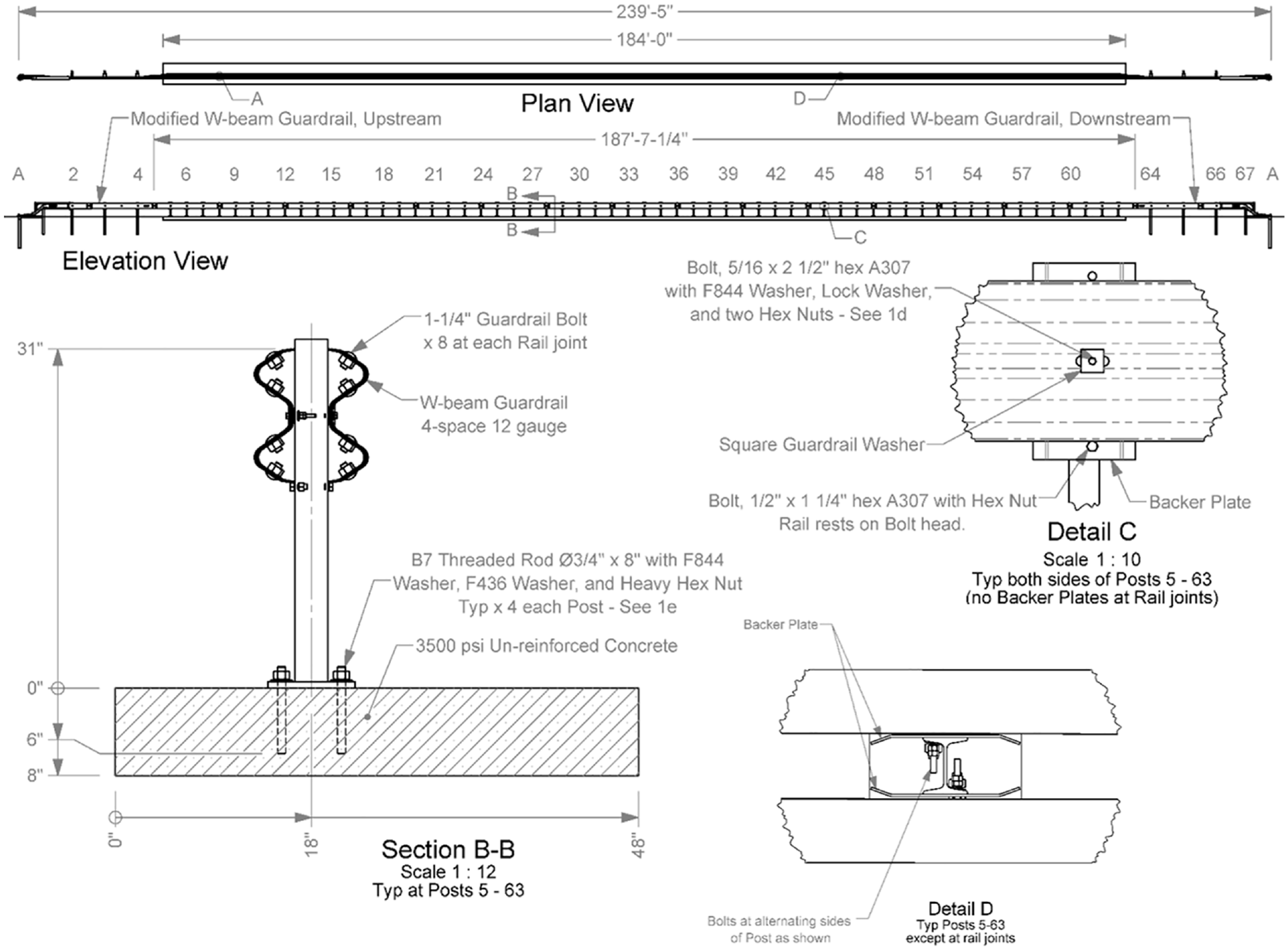
Test installation drawing.
Test installation drawing continued.
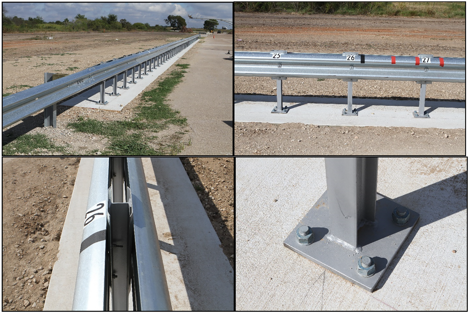
Test installation photos.
The top of the rail was 31 in. above the top of the concrete slab. Each end of the weak-post median guardrail transitioned to a standard strong-post W-beam guardrail and was terminated with an abbreviated guardrail end terminal that was only used to provide anchorage for these tests.
Test Details and Results
Test 3-10 (Crash Test 440522-01-01)
MASH Test 3-10 was performed with the surface-mounted weak-post median guardrail system. A 2381-lb 2015 Nissan Versa impacted the guardrail 40.8 in. upstream of post 28. The target impact point was 42 in. ± 12 in. upstream of post 28. The impact speed and angle of the vehicle were 62.3 mph and 25.3 degrees, respectively.
At 0.042 s after the impact, the vehicle began to redirect. The vehicle was parallel to the test installation at 0.273 s. At 0.54 s, the vehicle exited the installation at a speed of 51.3 mph, with a heading angle of 9.9 degrees and a trajectory of 7.6 degrees.
Posts 28–34 had their upstream traffic-side flange torn at the base. The rail was scuffed and deformed at impact. No cracks or concrete damage were observed around the post baseplates. The baseplates and their epoxy anchors were also undamaged. The backer plates remained attached to the posts. The maximum dynamic and permanent deflection of the barrier were 18.7 and 15.1 in., respectively. The working width was 31.6 in.
The maximum occupant compartment deformation of the vehicle was 2 in. in the front door area, below the seat. The occupant risk numbers were within MASH thresholds. The maximum occupant impact velocity (OIV) was 22.2 ft/s in the longitudinal direction. The maximum ride-down acceleration (RA) was 13.5g in the longitudinal direction. Figure 13 shows the test installation and vehicle after the crash test.
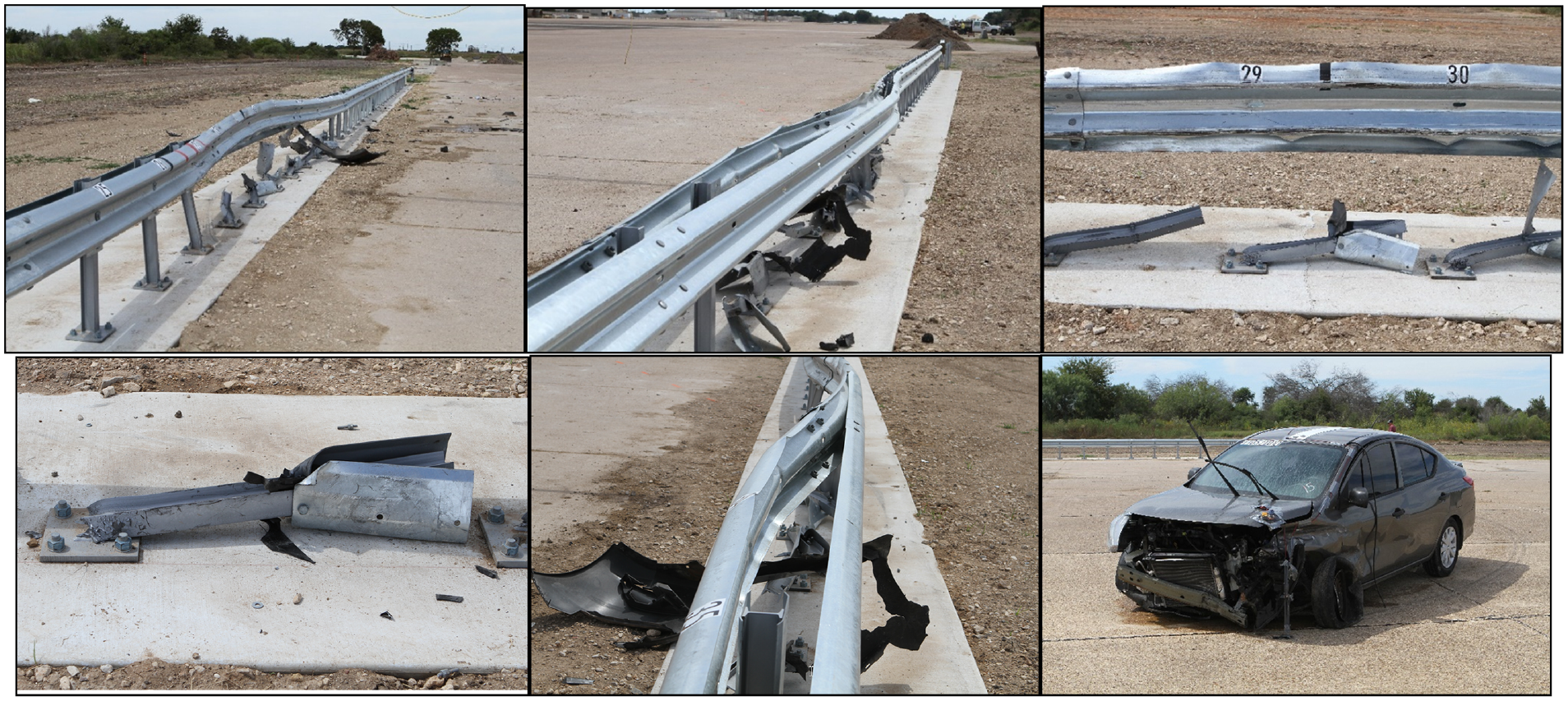
Test installation after Manual for Roadside Assessing Safety Hardware Test 3-10.
Based on the results of the crash test, the surface-mounted weak-post guardrail system passed MASH Test 3-10.
Test 3-11 (Crash Test 440522-01-02)
MASH Test 3-11 was performed with the surface-mounted weak-post median guardrail system. A 4995-lb 2015 Ram pickup impacted the guardrail impacted the guardrail 4.3 ft upstream of post 20. The target impact point was 4.0 ft ± 1 ft upstream of post 20. The impact speed and angle of the vehicle were 63.5 mph and 25.1 degrees, respectively.
At 0.037 s after the impact, the vehicle began to redirect. The vehicle was parallel to the test installation at 0.257 s. At 0.602 s, the vehicle exited the installation at 38.1 mph speed, with a heading angle of 14.0 degrees and a trajectory of 12.3 degrees.
The upstream edges of posts 19, 20, 21, and 23–25 were torn, and post 20 had a broken weld at the baseplate. The rail was scuffed and deformed at impact. No cracks or concrete damage were observed around the post baseplates. The baseplates and their epoxy anchors were also undamaged. The backer plates remained attached to the posts. The maximum dynamic and permanent deflection of the barrier were 37.8 and 30.3 in., respectively. The working width was 45 in.
There was no occupant compartment deformation of the vehicle. The occupant risk numbers were within MASH thresholds. The maximum OIV was 18.2 ft/s in the longitudinal direction. The maximum RA was 7.5g in the lateral direction. Figure 14 shows the test installation and vehicle after the crash test.
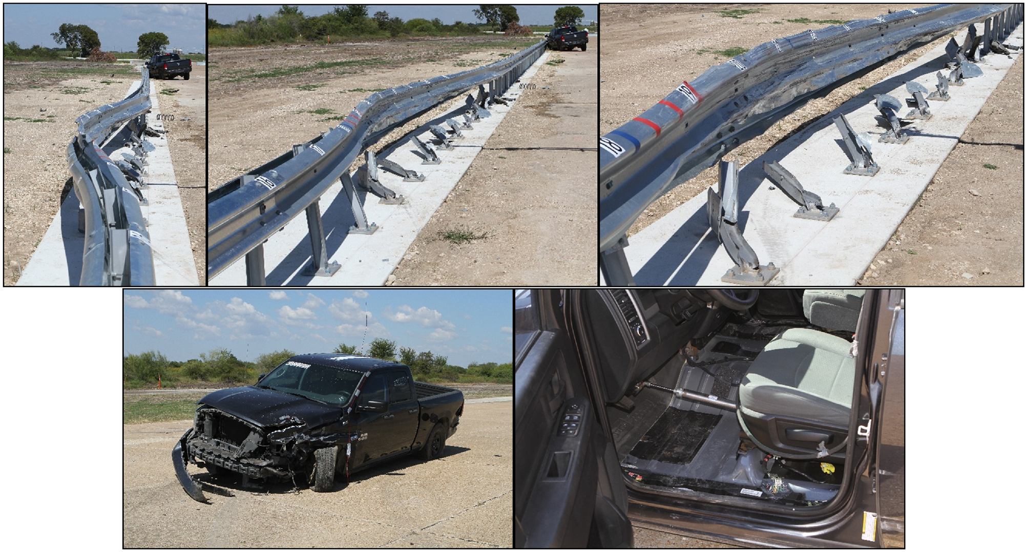
Test installation after Manual for Roadside Assessing Safety Hardware Test 3-11.
Based on the results of the crash test, the surface-mounted weak-post guardrail system passed MASH Test 3-11.
Conclusions
Having passed both MASH Tests 3-10 and Test 3-11, the newly developed surface-mounted median guardrail system is fully MASH TL-3 compliant. Since the design was crash tested on unreinforced concrete, it can also be used on reinforced concrete pavement or concrete decks.
In the test installation, the median guardrail was terminated at each end by changing over to the standard W6 × 9 strong-post W-beam guardrail, and then using a MASH-compliant end terminal (as shown in Figure 11). Since the deflection of the weak-post guardrail is comparable to the strong-post W-beam guardrail, a separate transition is not required ( 8 ). The half-post spacing of the weak-post system can be changed to full 75-in. post spacing of the strong-post W-beam guardrail. It should be noted that transitioning from the median guardrail to the roadside guardrail exposes the traffic to impacting the backside of the roadside guardrail. Therefore, this transition method should only be used if the ends of the guardrail will be located where the risk of impacting the back of the roadside guardrail is minimal. A more preferred way to terminate the guardrail is to use a MASH-compliant median guardrail end terminal.
The lighter surface-mounted median guardrail developed under this research is likely to be a good alternative to much heavier concrete median barriers for bridge applications, where bridge load reduction is important. Furthermore, currently there are no good alternatives to concrete median barriers when a median barrier is needed on concrete pavements. The new surface-mounted median guardrail is likely to be a more cost-effective alternate to concrete median barriers on concrete pavements.
Footnotes
Acknowledgements
This project was conducted in cooperation and sponsorship of Texas Department of Transportation (TxDOT). The authors would like to thank them for their support and funding of this research. The authors would also like to thank Christopher Lindsey, Kenneth Mora, Christopher Grose, Rostam Mahbod, and Wade Odell of TxDOT for their support in this research. The authors would also like to acknowledge support of Texas A&M University’s High Performance Research Computing in providing supercomputing machines used in this research for the FE analyses. The authors also acknowledge and thank the support of ANSYS LSTC for providing license of the commercial LS-DYNA software used to perform the FE analyses.
Author Contributions
The authors confirm contribution to the paper as follows: study conception and design: N.M. Sheikh, R.P. Bligh; data collection: N.M. Sheikh; analysis and interpretation of results: N.M. Sheikh; draft manuscript preparation: N.M. Sheikh. All authors reviewed the results and approved the final version of the manuscript.
Declaration of Conflicting Interests
The author(s) declared no potential conflicts of interest with respect to the research, authorship, and/or publication of this article.
Funding
The author(s) disclosed receipt of the following financial support for the research, authorship, and/or publication of this article: The research was sponsored by Texas Department of Transportation under TxDOT Project 0-7052.