
Abstract
The development of modern cities has often led to increased traffic congestion and limited usable space. One effective solution to these problems is to construct roadway tunnels, which can expand urban space and alleviate traffic congestion. However, building large underpass tunnels in urban areas, especially in soft ground, presents technical challenges owing to its extensive environmental disturbance. The pipe-umbrella box jacking method offers a promising solution to these challenges as this method does not require breaking the ground from the surface or disrupting surface traffic. This study reviews the key techniques of the pipe-umbrella box jacking method for constructing large rectangular tunnels with small burial depths in soft ground. The study focuses on three main technical issues: pipe umbrella installation, soil face excavation, and box jacking control. Furthermore, two tunnel projects in Shanghai, China, are presented as case studies to showcase the construction challenges and countermeasures during box jacking tunneling with pipe-umbrella. Practical construction experience has revealed that the installation of the pipe umbrella before box jacking serves as an effective method of ground pre-support. However, its performance can be influenced by factors such as pipe installation deviation and inter-pipe connection design. Both open-face steel grid extrusion (SGE) shields and closed-face earth pressure balanced (EPB) shields can be used for soil excavation during box jacking, with different work modes resulting in distinct ground deformation patterns. Additionally, lubrication grouting has been found to effectively reduce friction resistance and affect vertical ground deformation. The study also examines the lessons learned from case studies and proposes optimization measures. This study can serve as a valuable reference for the tunneling industry, providing insights into the pipe-umbrella box jacking method and its application in constructing large rectangular tunnels in soft ground.
When it comes to constructing large roadway tunnels in urban areas, non-open-cut methods are typically preferred over the open-cut method because the former eliminate the need for excavation from the surface, resulting in reduced disturbance and less impact on the surrounding environment ( 1 – 3 ). Among the non-open-cut methods commonly used for constructing roadway tunnels, three main techniques stand out: the boring method, the New Austrian Tunneling Method (NATM), and the box jacking method. The boring method is often the suitable choice, both technically and economically, for constructing long and deep tunnels with a circular cross-section. This method involves the use of tunnel boring machines (TBMs) to excavate the tunnel and install the prefabricated lining simultaneously. However, NATM is preferred for tunneling in rock and stiff soil ground. It involves a sequential excavation and support process in which the tunnel is excavated in small sections, and immediate support is provided using shotcrete and rock bolts. In contrast, the box jacking method is a competent option for constructing large rectangular tunnels or culverts with shallow depths in soil ground. With the box jacking method, prefabricated tunnel segments are pushed into the ground using hydraulic jacks. This method is particularly useful for building underpass tunnels beneath heavily congested urban streets, displacement-sensitive highways, or railways in which the open-cut method is not preferable or allowed ( 4 , 5 ).
The box jacking method typically refers to the tunneling method of jacking several prefabricated rectangular tunnel segments successively, while simultaneously (or stepwise) excavating the front face manually under the protection of an open-face shield, or directly using a closed-face shield machine. This method is similar to the pipe jacking method, which is commonly used for installing small utility tunnels or pipelines with a diameter below 3 m ( 6 – 8 ). In the case of constructing large cross-section tunnels using the box jacking method, such as tunnels as wide as 36 m and as high as 10 m, and with shallow depths as small as 5 m, the soil arching effects within the ground above the tunneling face are very weak ( 9 ). Without proper ground pre-support or reinforcement, there is a high risk of large ground deformation or even complete collapse during the tunneling process. Therefore, it is crucial to implement effective ground support or reinforcement methods to mitigate these risks.
Some conventional methods for reinforcing the ground include installing a single pipe roof along the upper boundary of the tunnel, using injective grouting ( 3 ), and using artificial ground freezing ( 10 ). However, the ground freezing technique tends to be expensive and time-consuming, whereas the subsequent thawing can lead to secondary ground settlement. Moreover, grouting through pipe roofs may not sufficiently mitigate ground settlement, especially in soft ground conditions. Therefore, there is a need for an alternative ground reinforcement or pre-support method to control ground disturbance when using the box jacking method to construct large rectangular tunnels in shallow depths of soft ground. The pipe umbrella, which is an adaptation of the traditional pipe roof, has shown promise in achieving this objective ( 11 , 12 ).
The pipe-umbrella box jacking method is gaining popularity, particularly for constructing large underpass tunnels beneath busy urban roads in densely populated cities. In China, several tunnel projects have successfully implemented this method over the past two decades, and two notable projects, the Beihong Road Underpass Tunnel (34.2 m × 7.8 m) and Tianlin Road Underpass Tunnel (19.8 m × 6.4 m), have marked significant milestones for the use of the pipe-umbrella box jacking method in mainland China. These projects serve as prime examples that demonstrate the technical suitability of this construction method for shallow tunneling in soft ground. Given its potential for constructing large tunnels with small burial depths in soft ground, it would be beneficial to the tunneling community to conduct a technical review of this promising technique and summarize the experience and lessons learned from these representative projects.
The objective of this study is to provide a detailed technical review of the pipe-umbrella box jacking method through the examination of two case studies. In this review, specific attention is given to key technical aspects related to the installation of the pipe umbrella, soil excavation, and box jacking control. Additionally, the field performance and technical lessons learned from two case studies, namely the Beihong Road Underpass Tunnel and Tianlin Road Underpass Tunnel in Shanghai, China, are thoroughly investigated and assessed.
Pipe-Umbrella Box Jacking Method and Its Key Technical Issues
The box jacking method is commonly used for constructing narrow rectangular pedestrian underpasses or utility tunnels, typically with widths less than 10 m ( 5 , 13 ). In such cases, a pipe umbrella is not necessarily required. However, this study primarily concentrates on the construction of wide rectangular tunnels with large cross-sections, reaching dimensions as large as 34.2 m × 7.8 m. These tunnels are constructed in soft ground, with relatively shallow burial depths, usually significantly smaller than the tunnel width. In this scenario, a pipe umbrella plays a crucial role as a supplementary ground pre-support.
Pipe-Umbrella Box Jacking Method
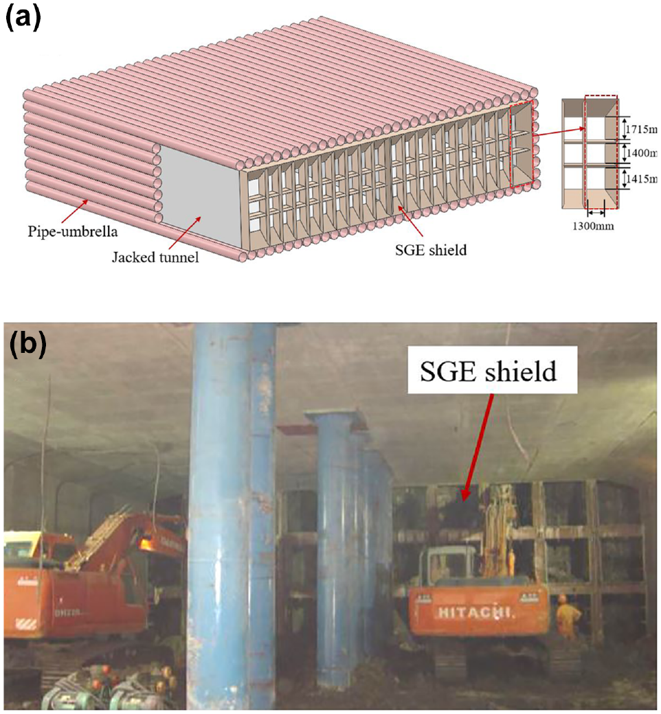
The pipe-umbrella box jacking method is a tunneling technique that involves a sequential jacking of prefabricated box segments, whereas under the protection of a pre-installed pipe chain around the tunnel circumference (refer to Figure 1). This tunneling method consists of two primary sub-procedures: pipe umbrella installation and box jacking. To begin with, a set of custom-made steel pipes are sequentially inserted into the ground and extended from the launch shaft to the reception shaft using the conventional pipe jacking method. These installed pipes create a sturdy pipe array distributed along the circumference of the designated tunnel boundary (see Figure 2). Subsequently, a series of precast concrete segments are successively jacked into the ground along the designated tunnel axis, accompanied by simultaneous soil excavation and removal, until the entire tunnel length is finished longitudinally (as depicted in Figures 3 and 4).
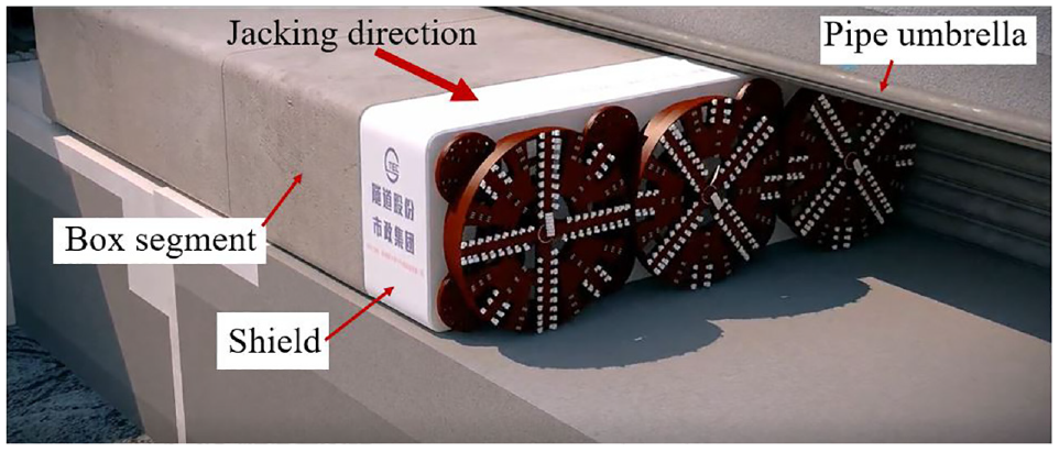
Schematic of pipe-umbrella box jacking method (using an earth pressure balanced [EPB] shield).
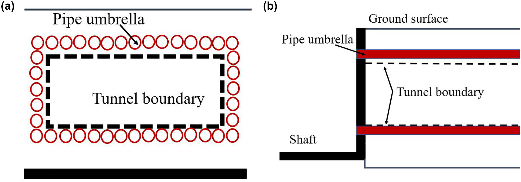
Schematic of pipe umbrella installation: (a) front view and (b) side view.
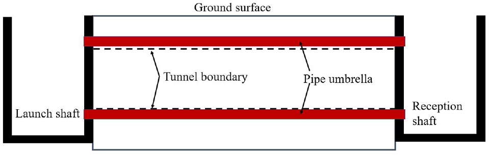
Site preparation and pipe umbrella installed before box jacking.
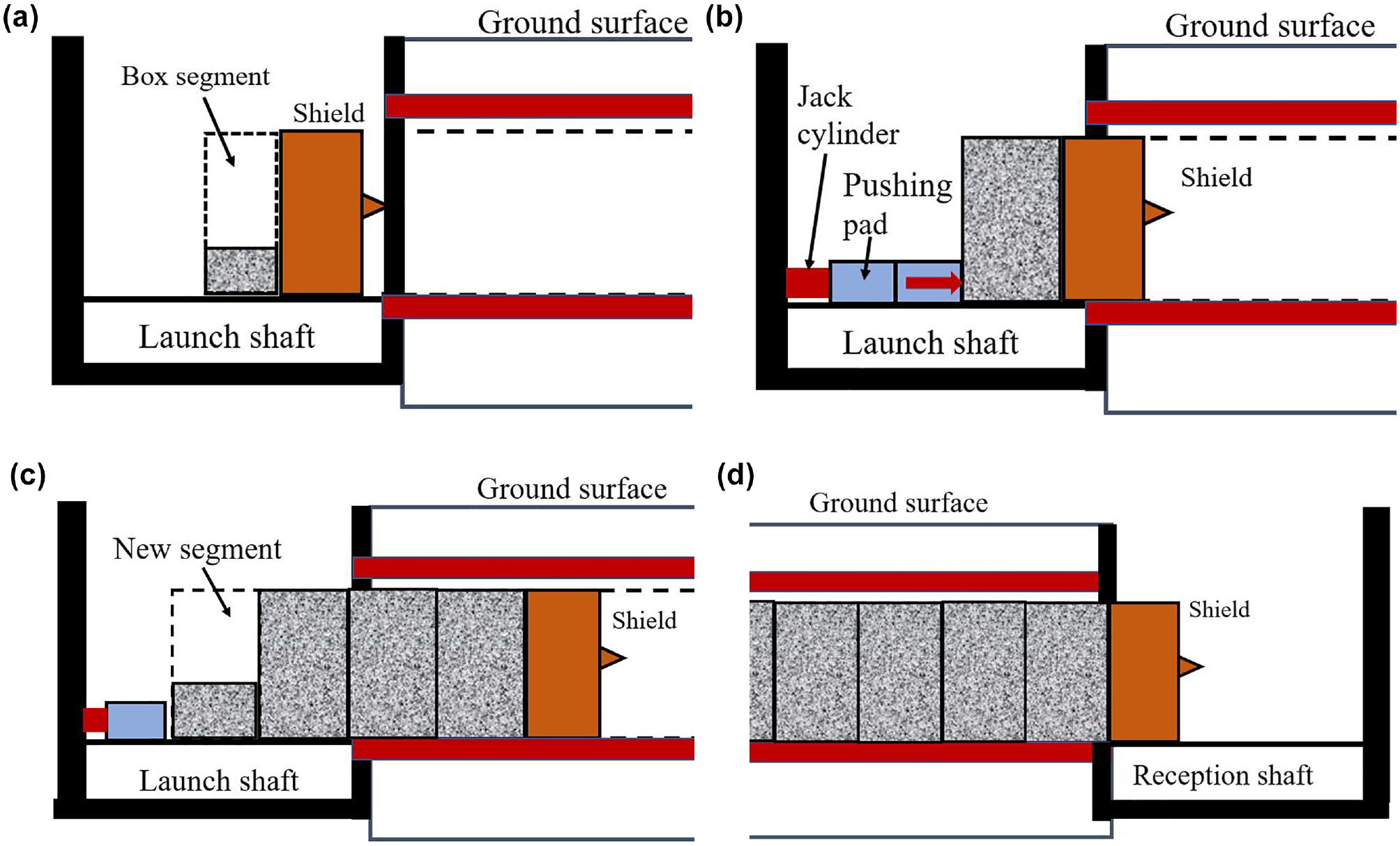
Main construction procedures of pipe-umbrella box jacking method: (a) shield assembly and box segment concreting, (b) initial launch of the shield, (c) new box segment concreting, and (d) reception of the shield.
The pipe-umbrella box jacking method follows a specific workflow, as depicted in Figures 3 and 4. Once the pipe umbrella is installed (refer to Figure 3), a head shield, which can be open-face or closed-face, is assembled and prepared in the launch shaft. At the same time, the first tunnel segment is cast on-site and cured until it reaches the required strength grade (see Figure 4a). Following this, the jack cylinder groups are positioned against the reaction wall, and several pushing pads are inserted between the freshly cast segment and the cylinders (as shown in Figure 4b). It should be noted that while the reaction wall is mentioned in this scenario, there are other methods of establishing the jack-force transferring systems, such as using an inverted slab with shear keys or ties connected to the excavation support, or a temporary steel frame ( 12 ), among others. The hydraulic cylinders then begin to operate, exerting thrust on the segment and the shield, pushing them forward to penetrate the ground until there is sufficient workspace to cast a new tunnel segment (see Figure 4c). Excavation of the face and removal of soil occur simultaneously with the jacking process of each segment. By repeating this cycle of “segment concreting-jacking”, the tunnel is completed when the head shield reaches the reception shaft (see Figure 4d).
Key Technical Issues
In the following section, the key technical issues of the pipe-umbrella box jacking method will be discussed, which includes the installation of the pipe umbrella, soil face excavation, and the control of box jacking.
Pipe Umbrella Installation
In the pipe-umbrella box jacking method, the pipe umbrella serves as an effective way to pre-support the ground and further mitigate adverse ground deformation caused by tunneling. Notably, the pipe umbrella differs from the conventional pipe roof that has long been used as an advanced ground pre-support in NATM. The conventional pipe roof typically consists of a row of isolated spaced (or sometimes overlapping) pipes installed only along the upper side of the tunnel boundary, with a length ahead of the excavation face, and subsequent grouting could be conducted through the holes in the pipes (Figure 5a). However, for box jacking in very soft ground, the single pipe roof may not provide sufficient ground support owing to the low stiffness of individual pipes and a weak shear connection between adjoining pipes, which potentially results in a significant ground settlement or even collapse as reported in Wang et al. ( 14 ).
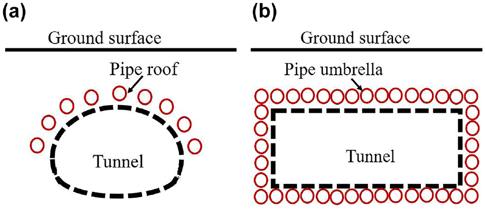
Ground reinforcement using (a) single pipe roof in New Austrian Tunneling Method (NATM) tunneling and (b) circumferential pipe umbrella in box jacking tunneling.
Unlike the conventional single pipe roof, the pipe umbrella in the pipe-umbrella box jacking method consists of multiple interconnected steel pipes installed along the circumference of the tunnel (refer to Figure 5b). It is worth noting that in certain box jacking projects conducted in stiff soil layers, the pipe array beneath the tunnel bottom may be removed as an alternative approach. These pipes are typically manufactured with specialized locking parts, as illustrated in Figure 6, enabling strong interconnections between adjacent pipes. Additionally, the pipes used in the pipe umbrella method have a larger cross-section compared with those used in conventional pipe roofs. During construction, the pipes are horizontally jacked into the ground, from the launch to the reception shafts, using the regular pipe jacking method. Once the installation is complete, the pipes form an integrated “umbrella” structure that behaves similarly to a thick slab with bending stiffness. This configuration provides robust resistance against potential ground deformations that may occur during subsequent box jacking operations ( 15 ).
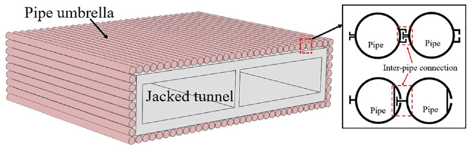
Pipe umbrella and inter-pipe connection.
To increase the bending stiffness of the pipe umbrella, some of the pipes are further filled with concrete, whereas the remaining hollow pipes are used as channels for monitoring ground deformation during the pipe installation and box jacking process ( 9 , 15 ). During the installation of the pipe umbrella, it is important to address two key technical concerns: pipe deviation control and inter-pipe connection. Pipe deviation is a common occurrence during the pipe jacking process. However, in cases of significant trajectory deviation, the installed pipes may intrude on the tunnel boundary, potentially resulting in direct contact between the shield and the pipes (as shown in Figure 7). This scenario can pose a major obstacle or even cause complete failure of the box jacking process. Therefore, it is vital to control the deviation of the pipe axis within specified limits to ensure smooth box jacking. Additionally, it is highly recommended to maintain a reserved gap (typically 10–20 cm) between the pipe and the external boundary of the tunnel, since this gap provides a safety margin to the risk of shield-pipe contact in case of small to moderate deviations during pipe jacking.
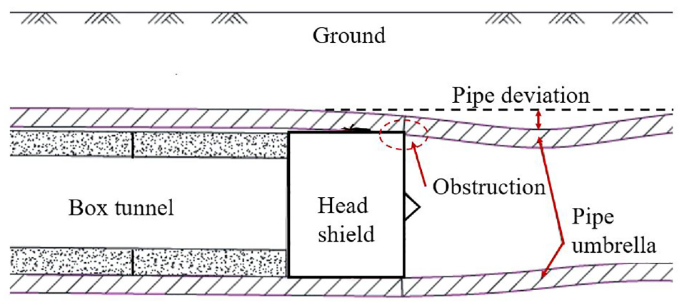
Obstruction of box jacking owing to significant pipe installation deviation.
The inter-pipe connection is a crucial component of the pipe umbrella system, and Figure 8 depicts two typical designs of such connections that have been used in actual box jacking projects. These connections are typically achieved using special pipes that are fitted with prefabricated connecting parts, namely the plug and the socket. It is important to note that the successful formation of this connection relies on the precise installation of the pipe jacking process. Moreover, if the gap between the two pipes is not properly sealed, it can act as a pathway for groundwater flow, which may introduce additional risks during the box jacking process. In Figure 8, the void within the pipe socket can initially be filled with waterproofing material, such as gel, soft foams, or bentonite, before being jacked into the ground. This initial sealing helps when the adjoining pipe is subsequently jacked into place. However, the waterproofing performance of these filling materials may not last throughout the entire construction period. Therefore, it is recommended to further enhance the sealing of the inter-pipe void by replacing it with grouting, as illustrated in Figure 8. This is particularly advised when tunneling through water-rich ground strata. The grouting process offers a more reliable and long-lasting waterproofing solution for the inter-pipe connection, reducing the risk of groundwater infiltration during the box jacking process ( 16 , 17 ).
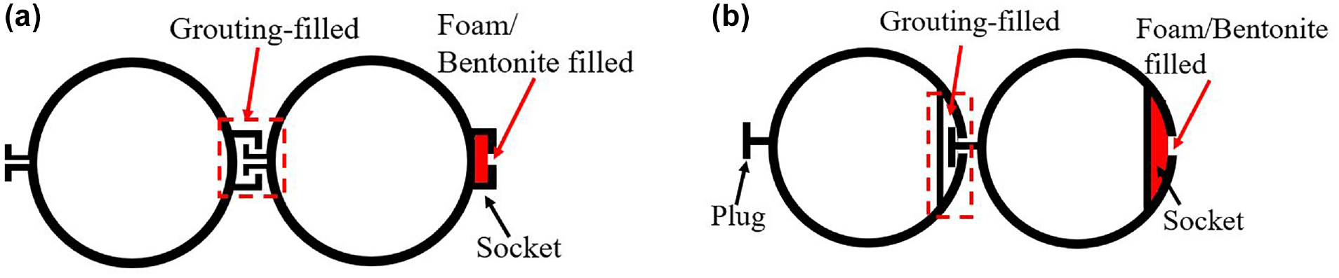
Illustration of the typical design of inter-pipe connection and sealing: (a) external-lock type and (b) internal-lock type.
Soil Face Excavation
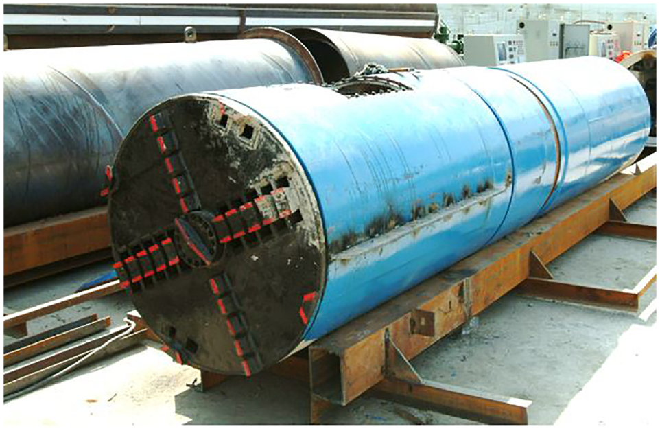
In box jacking construction, the head shield can be either an open-face steel grid extrusion (SGE) shield (see Figure 9) or a closed-face earth pressure balanced (EPB) shield (see Figure 10). The SGE shield does not have mechanized cutter-wheels and the front face is usually excavated and discharged manually. Typically the SGE shield is attached to the tunnel head, and its cross-section is equipped with sharp steel blades circumferentially which can easily extrude into the ground by jacking force. Moreover, the SGE shield face is usually divided into multiple small compartments by a mesh grid, since this can offer some face support when soil excavation is conducted stepwise, as depicted in Figure 9. Compared with a full-face EPB shield with mechanized cutter-wheels, the SGE shield has a much simpler machinery configuration and a lower equipment cost, which makes it still popular in box jacking constructions. However, it bears some defects such as requiring a higher level of manual labor for soil excavation and a more excellent operation expertise in ground deformation control than an automatic mechanized EPB shield.
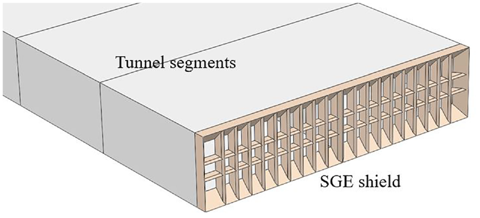
Soil face excavation by a steel grid extrusion (SGE) shield in box jacking.
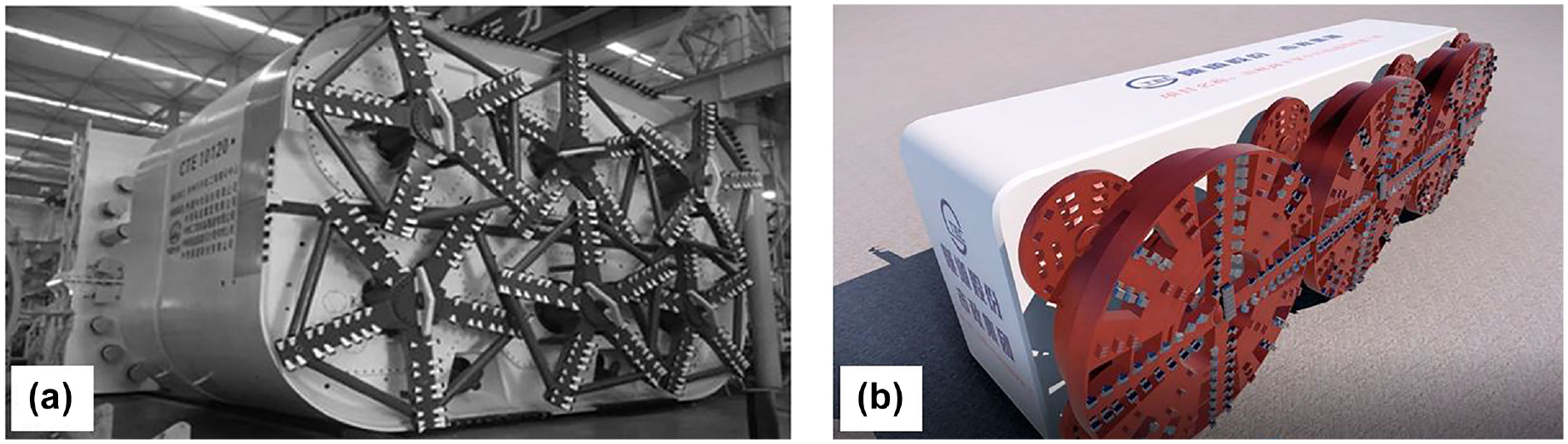
Earth pressure balanced (EPB) shields for soil face excavation in box jacking in (a) stiff ( 19 ) and (b) soft ground.
In contrast to the SGE shield, the full-face EPB shield, as shown in Figure 10, offers several advantages in reducing human labor and mitigating ground disturbance. The slurry-type shield is not commonly used in box jacking construction owing to the difficulties in controlling slurry pressure in shallow tunneling. The EPB shield used for box jacking tunnels is typically equipped with multiple cutter-wheels of different dimensions to excavate a rectangular cross-section. Additionally, an EPB shield enables better control of the face support by adjusting the earth pressure through proper soil discharging rates, which is similar to regular EPB shield tunneling. The soil mucks outlet through the screw conveyors are further removed to the outside tunnel by trunks or railcars running on temporary tracks ( 18 – 20 ). Overall, the use of an EPB shield in box jacking construction offers benefits as regards reducing labor and ground disturbance control.
Box Jacking Control
In box jacking construction, there are three critical issues that require attention: friction mitigation, box posture control, and ground deformation control. To ensure the smooth pushing of a large cross-section concrete tunnel, the total jacking force provided by hydraulic cylinders must exceed the total resistance. This total resistance primarily includes the front face resistance and the circumferential friction on the soil–tunnel interface ( 15 , 20 ). When box jacking is performed in shallow ground, the significant friction between the box segments and the surrounding soil tends to drag the upper ground forward, which can result in severe horizontal ground deformation, as reported in Wang et al. ( 14 ). The pipe umbrella isolates the box segments from the surrounding ground and helps reduce such drag effects. However, it is still necessary to use synchronous lubrication grouting to further reduce the frictional resistance. During the box jacking process, lubrication grouting is prepared on-site, supplied through ducts, and then injected into the prefabricated holes distributed along the circumference of the concrete box segment, as shown in Figure 11, a and b. The typical composition of lubrication grouting includes bentonite, sodium carboxymethyl cellulose (CMC), sodium carbonate, and acrylamide ( 20 ). Reducing the friction can minimize the total jacking force required, resulting in smoother and more efficient box jacking operations.
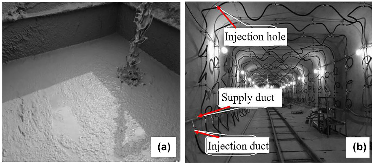
Synchronous lubrication grouting in box jacking: (a) lubrication mix and (b) grouting from inside tunnel ( 20 ).
In box jacking construction in soft ground, settling of the jacked segments owing to their self-weight can lead to jacking deviation. However, in pipe-umbrella box jacking, the pipe array installed below the tunnel bottom serves as a stiff sliding channel for the jacked tunnel, which significantly compromises its settlement tendency. Furthermore, if the jacking force is transferred via the pushing pads (between the cylinders and the end segment) solely placed at the lower positions of the cross-section (see Figure 12) rather than a thrust frame that can potentially introduce jack forces on the sidewalls and roof, the resultant eccentric thrust force could trigger a significant correction moment, which can lead to upward movement or “drafting” of the head shield. Additionally, the uneven distribution of earth pressure on the tunneling face can cause the shield to tilt on the horizontal plane. If excessive trajectory deviation occurs, the shield may collide with the surrounding pipes and hinder the jacking process. Therefore, it is necessary to monitor and control the posture deviation of the shield within an acceptable threshold in box jacking construction.
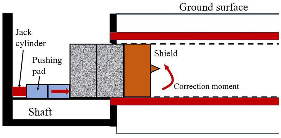
Schematic of the resultant correction moment at the front of tunnel boring machines (TBMs).
To mitigate the deviation of the EPB shield in the horizontal plane, three methods can be used. The first method involves adjusting the stroke (or thrust forces) of the individual cylinder to generate eccentric thrust forces on the horizontal plane. This means that the thrust forces are applied unevenly, creating a slight tilt in the shield machine to counterbalance the deviation. The second method is to adjust the rotation speed of the individual cutter-wheel. By changing the speed of specific cutter-wheels, the EPB shield can be guided in the desired direction and the deviation can be corrected. The third method involves changing the soil discharge rate of the screw conveyor, as shown in Figure 13. For instance, if a clockwise tilting of the shield machine (seen from the top) occurs on the horizontal plane, the rotation speed of the cutter-wheel C1 and the screw conveyor S1 is supposed to be increased a bit to speed up the soil discharge, which helps correct the tilting deviation. In addition, the upward movement of the tunnel segments in the vertical plane can be counterbalanced by placing additional ballasting weights. It is important to note that the specific adjustments required for each method may vary depending on the specific conditions and deviations encountered during the box jacking operation. Careful monitoring and adjustment of these parameters are necessary to ensure that the EPB shield stays on the desired path and deviation is minimized.
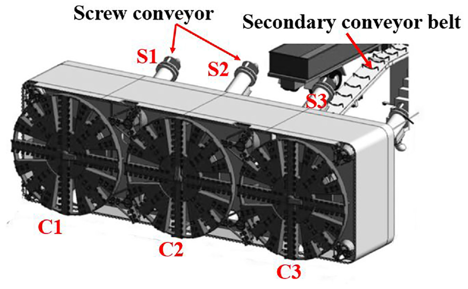
Earth pressure balanced (EPB) shield for soil excavation and discharge ( 18 ).
Typical Box Jacking Tunnel Cases
Two typical pioneering tunnel projects in Shanghai, China, are investigated and examined in this section, which serve as pioneering projects using the pipe-umbrella box jacking method. Both projects involved the construction of tunnels with a pipe umbrella for advanced ground pre-support, but they differed as regards the shield type used for soil excavation. In one project, an SGE shield (open-face SGE shield) was used for soil excavation, whereas in the other project, an EPB shield (closed-face EPB shield) was used. These two projects provide valuable insights and technical summaries of the pipe-umbrella box jacking method, serving as a reference for the tunneling industry. Through the detailed investigation and analysis of these projects, researchers and engineers can gain a comprehensive understanding of the challenges associated with implementing the pipe-umbrella box jacking method in soft ground conditions.
Beihong Road Underpass Tunnel
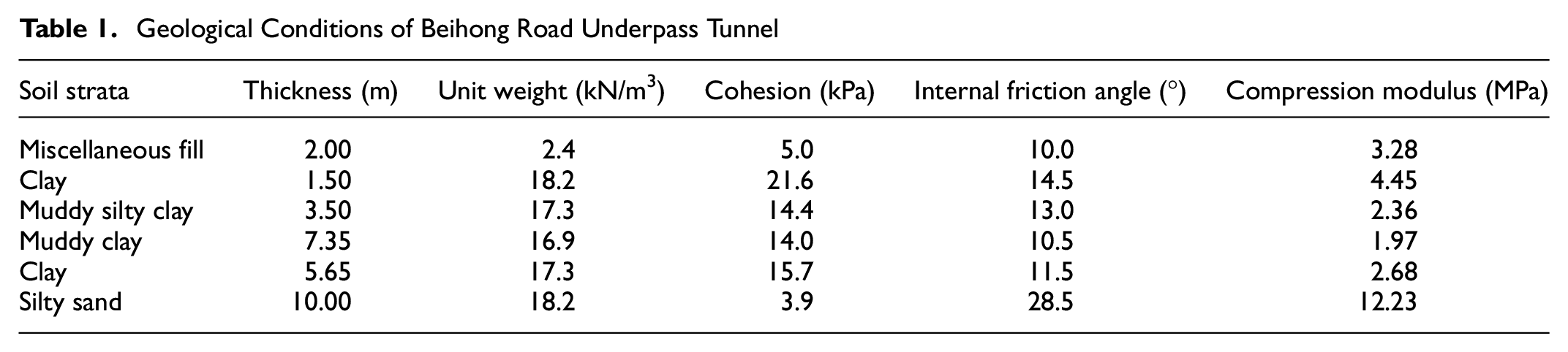
The Beihong Road Underpass Tunnel is a part of the Middle-Ring Expressway in Shanghai, China. This urban roadway tunnel is constructed beneath the Hongqiao Road and has a large cross-section measuring 34.2 m in width and 7.85 m in height (Figure 14). Construction of this tunnel began in the year 2003 and was completed in 2005. The box jacking section of the tunnel spans a length of 125 m and is divided into eight concrete segments ( 21 ). The thickness of the tunnel structures at the roof, bottom plate, and sidewall are 1.3 m, 1.42 m, and 1.0 m, respectively. Owing to its location in a busy urban area, the open-cut method is not appropriate owing to its extensive impact on the surrounding environment. Additionally, the tunnel was built in soft ground, primarily saturated soft clay, and had a shallow burial depth of only 5.0 m. These factors posed a high risk of excessive ground settlement during tunneling. Despite the existing ground reinforcement methods such as artificial ground freezing, the pipe umbrella has been, for the first time in mainland China, explored to build this box jacking tunnel in soft ground. Table 1 provides information on the primary physical and mechanical properties of the soil strata for this project. Overall, the Beihong Road Underpass Tunnel was constructed using box jacking in soft ground conditions, with a focus on minimizing environmental impact and managing the risk of ground settlement.
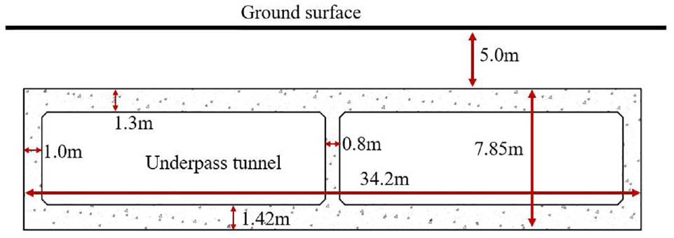
Cross-section of Beihong Road Underpass Tunnel.
Geological Conditions of Beihong Road Underpass Tunnel
Pipe Umbrella Installation
The pipe umbrella is an important component of the pre-support system used in box jacking construction. In this project, the pipe umbrella consisted of 80 hollow steel pipes, and each pipe had an internal diameter of 950 mm and a thickness of 10 mm. There were three types of pipes used in the project: standard pipes, starting pipes, and corner pipes, as depicted in Figure 15. Each pipe was fitted with special locking parts, either a plug and socket or a double socket, which were welded onto the circumference of the pipe ( 22 ). This locking mechanism ensured a secure connection between adjacent pipes. The installation of the pipe umbrella began by jacking the starting pipe into the ground. The interlocking constraint provided by the finished pipe helped to reduce the trajectory deviation of the adjoining new pipe. To enhance the waterproofing of the inter-pipe connection, the void within the pipe socket was initially filled with soft foam. Once the pipe jacking was completed, the foam was replaced with grouting to prevent any potential groundwater inflow. This grouting process provided a reliable and long-lasting solution for sealing the inter-pipe connections and minimizing the risk of water infiltration during the box jacking process. The installation of the pipe umbrella involved the use of eight slurry-type pipe jacking machines, as shown in Figure 16.
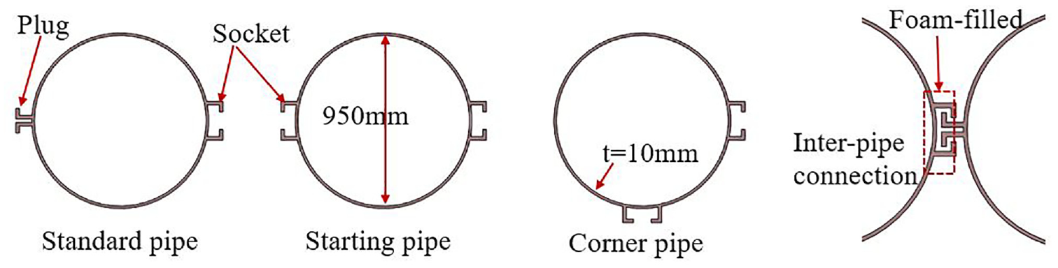
Schematic of pipes and inter-pipe connection.
Slurry-type pipe jacking machine used in pipe umbrella installation.
Given the possible deviations in the pipe jacking and possible vertical deflection longitudinally (when subjected to ground loadings), the pipes may displace to invade the central tunnel boundary. To prevent this undesired pipe–tunnel contact, it is necessary to set a gap between the pipes and the tunnel’s external boundary. The magnitude of this gap should be determined by taking into account the estimated installation error (the work quality of the contractors). In this project, the gaps are set as 20 cm at the top, 10 cm at the two sides, and 0 mm at the bottom (see Figure 17). After the pipe umbrella installation, 54 of the 80 pipes were filled with low-strength concrete to increase their flexural stiffness and further enhance the structural integrity of the pipe umbrella. The 54 filled pipes included 20 on top, 28 at the bottom, and 6 on the two sides. The unfilled pipes were left empty and served as channels for deformation measuring and additional grouting. During the pipe umbrella installation, it was observed that some local damage occurred to the inter-pipe connections owing to large deviations in the jacking of several pipes. To address this issue, additional grouting was injected into the space between the pipes that were considered divided apart. This remedial action helped to restore the integrity of the pipe umbrella and ensure its effectiveness. It is also suggested that using pipes with greater stiffness, which can be achieved by increasing the wall thickness, can help reduce torque deformation and jacking deviation. This indicates that selecting pipes with appropriate characteristics is important to ensure a reliable pipe umbrella system.
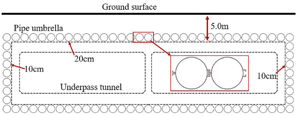
Schematic of pipe umbrella installation.
Box Jacking
During the box jacking process, an open-face SGE shield was assembled and integrated into the front of the first tunnel segment. The SGE shield is equipped with a mesh grid on the center and sharp penetration blades circumferentially, as shown in Figure 18. These blades enhance penetration efficiency, whereas the meshed grid divides the face into smaller sections, allowing for easier stepwise face excavation. In the initial stage of box jacking, the soil within a small distance ahead of the shield was excavated by backhoe excavators or man-hand digging and further discharged outside the tunnel by trucks. Following soil excavation, the SGE shield was slowly pushed forward in small steps, and this “prior excavation-jacking” process was repeated, which can be referred to as the prior-excavation mode.
Schematic of (a) box jacking using a steel grid extrusion (SGE) shield and (b) field soil excavation viewed from inside tunnel.
In the construction process, the lengths of the first and second segments are set at 18.0 m, while the third segment is 4.0 m in length. The fourth to seventh segments were all 17.5 m long, and the eighth segment measured 15.2 m. During the early stages of box jacking, the ground settlement was controlled within acceptable limits. However, during the jacking of the second segment, field monitoring revealed a significant ground settlement. This settlement reached a maximum of approximately 270 mm, occurring approximately 3 m ahead of the excavation face, far exceeding the expected deformation levels ( 21 ). Although this settlement occurred outside the Hongqiao Road boundary and did not affect the ground traffic, the contractor halted the jacking work to conduct further investigations and optimize the subsequent jacking operations.
The excessive ground settlement is primarily attributed to the improper soil-excavation mode adopted. In this project, the soil volume enclosed by the pipe umbrella was not reinforced. Although the face can remain self-stable and no face collapse occurs, the soil excavation mode should be properly planned to control ground deformation. During the jacking of the second segment, the soil ahead of the shield is typically removed, creating a void between the mesh grid and the front face. In this “prior-excavation” mode, the shield fails to provide sufficient support to the face, resulting in significant surface settlement, as depicted in Figure 19a. This is the primary cause of the observed excessive settlement during the jacking of the second box segment.
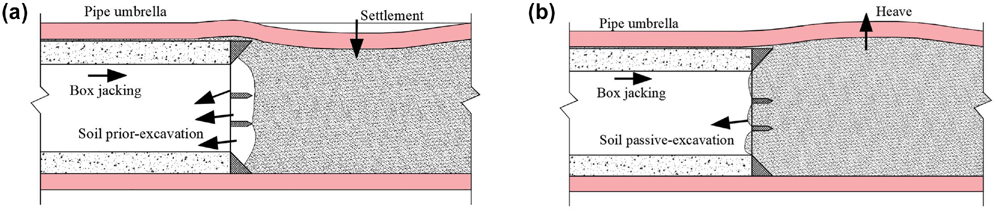
Schematics of box jacking in soil (a) prior-excavation and (b) squeeze-excavation modes.
In the third segment jacking, a new excavation procedure called the squeeze-excavation mode was implemented. This mode involved directly thrusting the SGE shield forward to penetrate the ground face without any previous excavation. The highly saturated soft soil mucks would then flow through the mesh grid toward the interior and further be discharged, as illustrated in Figure 19b. Compared with the prior-excavation mode, the squeeze-excavation mode provided stronger face support, eliminating settlement and the significant squeezing force could even trigger ground heave, as shown in Figure 19b. Figure 20a shows the ground deformation (baselined on the starting of the third segment jacking) measured during the first and second working days of the third segment jacking (lasting for 2 days). It can be observed that the ground deformations transitioned from settlement to heave, with a significant ground heave of approximately 36 mm observed 7 m ahead of the shield face. Figure 20b presents the measurements taken during the first 3 days of the fourth segment jacking. A maximum heave of about 34 mm was observed approximately 2 m behind the shield head. Overall, the field monitoring data indicate that ground heaves occur when the SGE shield operates in the squeeze-excavation mode, rather than settlement. Additionally, the lubrication grouting pressure applied to the tunnel circumference also contributes to this heave by imposing an uplift force on the top pipes.
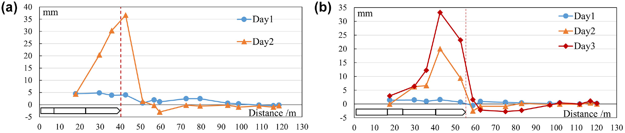
Ground deformation during the (a) third and (b) fourth segment jacking (x-axis is the distance to the shield head, the vertical dot line marks the shield head location) ( 22 ).
After the completion of box jacking, the instant ground heave triggered by the squeeze force of the SGE shield will gradually decrease and tend to converge, since the squeeze forces are temporarily removed and the lubrication grouting pressure is reduced. Figure 21 ( 22 ) illustrates the ground surface deformation of three monitoring points during a pause after the jacking of the fourth segment. The monitoring points, namely P23, P19, and P16, are situated along the centerline of the tunnel. P16 is located approximately 4.5 m before the shield head, whereas P23 and P19 are about 11 m and 17 m behind the shield head, respectively. Note that the ground deformation (heave) is set to zero (baseline) at the completion of box jacking (time = 0 day), and negative values indicate a settling tendency. From the graph it can be deduced that the ground heave that occurred during the box jacking gradually recovers with time after the completion of the jacking process.
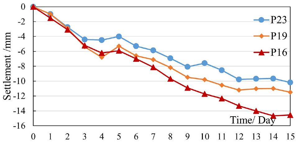
Ground surface deformation versus the pause time of box jacking.
The jacking force during the entire box jacking process was measured and the results are presented in Figure 22. The graph shows that the jacking force curve of the first two segments has a much steeper gradient compared with the subsequent sections. By the end of the second segment jacking, which corresponds to a total jacking distance of 36 m, the jacking force reaches about 150 MN (Meganewton). However, the gradient of the force curve decreases significantly in the subsequent jacking, and the maximum force only reaches about 220 MN at the beginning of the eighth segment jacking, which corresponds to a total jacking distance of about 110 m. It should be noted that in the jacking of the first two segments, the lubrication grouting injecting (applied on the tunnel circumference) was not properly conducted owing to damage to some grouting ducts. As a result, the reduction of tunnel–soil interface friction was not effectively achieved, leading to an excessively high jacking force. Starting from the third segment jacking, the damaged grouting ducts were repaired and lubrication grouting was properly conducted, which significantly reduced the required jacking forces. In summary, proper lubrication grouting plays a critical role in controlling the friction resistance during box jacking.
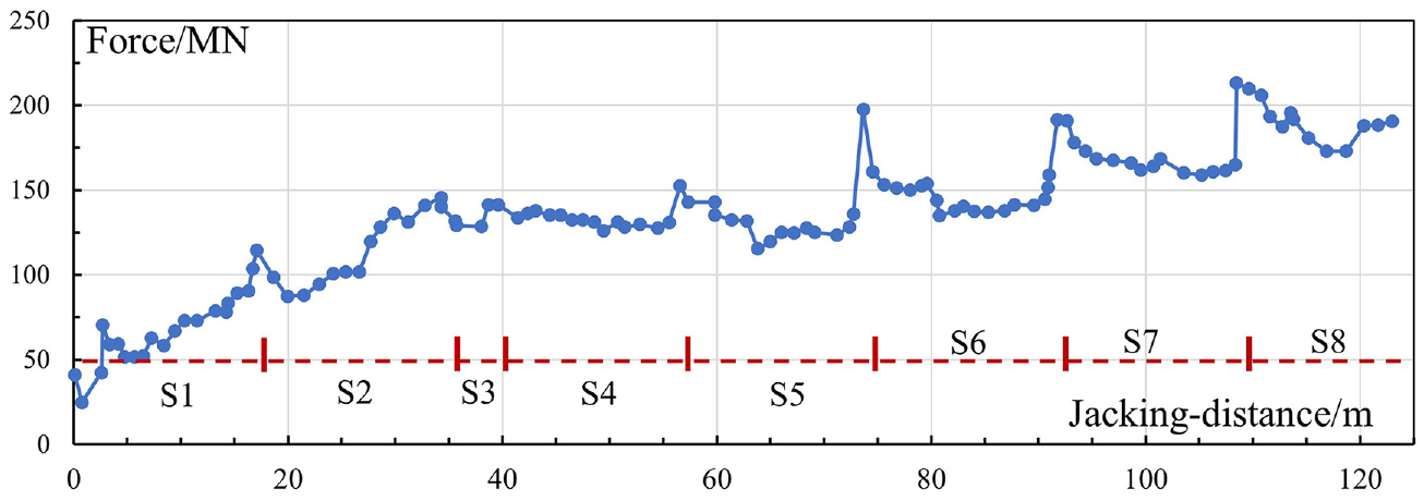
Total jacking force along with jacking distance.
Tianlin Road Underpass Tunnel
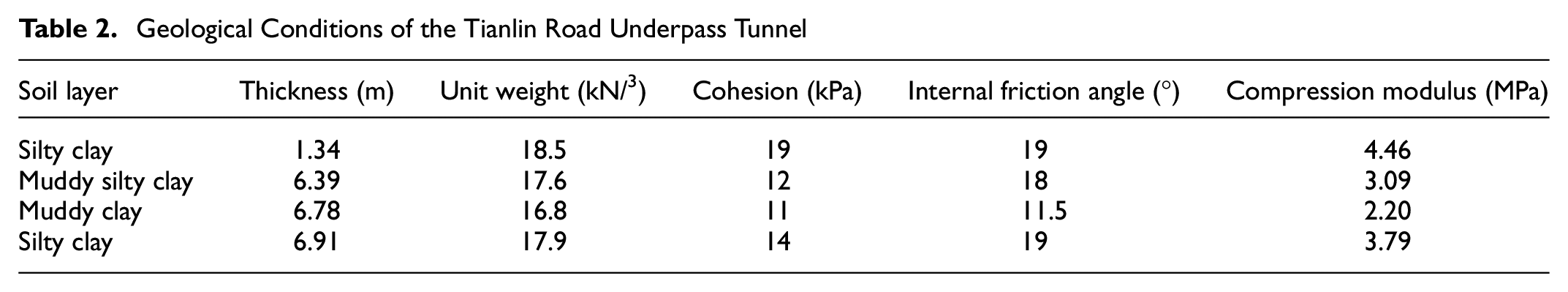
The Tianlin Road Underpass Tunnel was constructed beneath the Middle-Ring Expressway in Shanghai, China. It has a total length of approximately 696 m, with the box jacking section covering about 87.6 m. The jacked tunnel segment has external dimensions of 19.8 m in width and 6.4 m in height, with three motor lanes in the center and two additional pedestrian lanes on each side, as depicted in Figures 23 and 24. The box jacking tunnel has a burial depth of around 6.2 m (see Figure 25), and the geological strata at the site mainly comprise highly plastic and compressible mucky silty clay. Table 2 provides details of the soil layer types and their respective geotechnical properties. The groundwater table is approximately 1 m below the surface. To mitigate ground deformations, a pipe umbrella was constructed as a ground pre-support measure before box jacking ( 24 , 25 ).
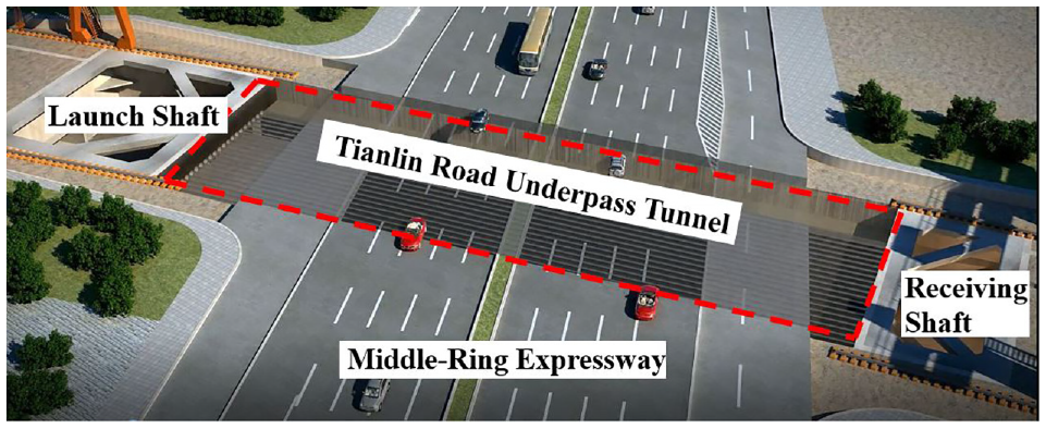
Bird’s eye view of the Tianlin Road Underpass Tunnel.
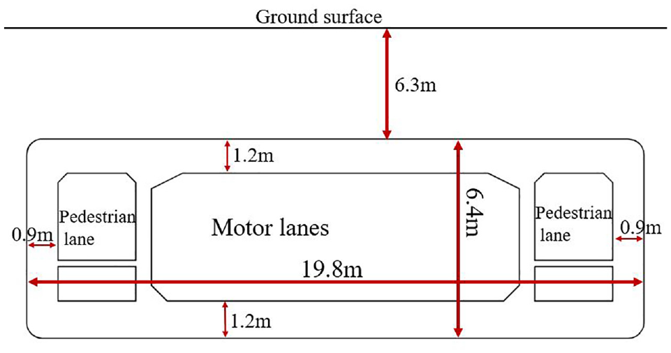
Cross-section of the Tianlin Road Underpass Tunnel.
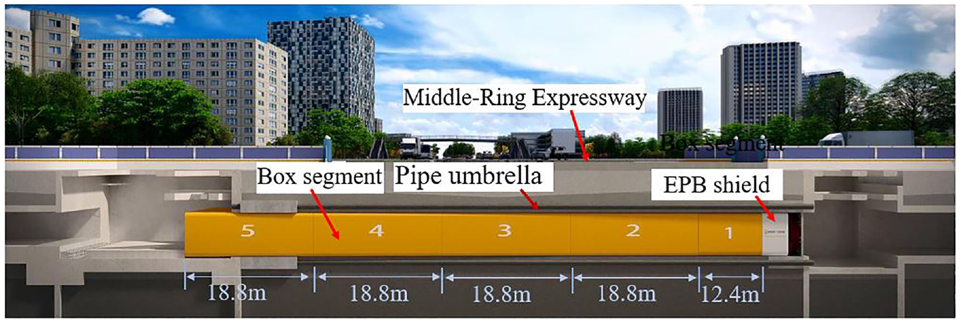
Longitudinal section of the Tianlin Road Underpass Tunnel.
Geological Conditions of the Tianlin Road Underpass Tunnel
Pipe Umbrella Installation
In this project, the pipe umbrella is composed of 62 steel pipes with special interlocking parts, as illustrated in Figure 26. Each individual steel pipe has an internal diameter of 800 mm and a thickness of 12 mm. Four types of pipes are used: the starting pipe, standard pipe, corner pipe, and closure pipe. The pipe jacking process typically begins with the starting pipe and concludes with the closure pipe. The pipe installation sequence is depicted in Figure 26, and four pipe jacking machines were used to install the entire pipe umbrella. To enhance the stiffness of the pipe umbrella, 55 pipes were filled with low-strength concrete, while the remaining seven hollow pipes were left unfilled to serve as channels for monitoring vertical deformations. Furthermore, a novel interlocking connection was developed for this project, which differs from the one used in the Beihong Road Underpass Tunnel (see Figure 17). The new type of connection comprises an external plug and an embedded socket, as shown in Figure 27. Before pipe jacking, the socket voids were initially filled with bentonite for waterproofing, and the small cuts were temporarily sealed using a very thin steel plate by point welding.
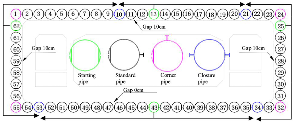
Schematic of pipe umbrella installation.
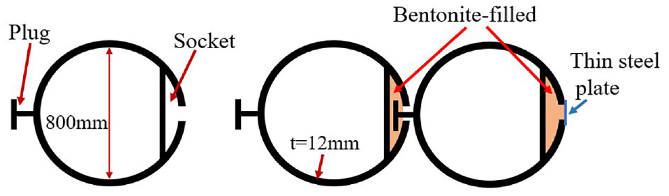
Schematic of a standard pipe (left) and inter-pipe connection (right).
The deviation of the pipes in the pipe jacking process is measured at different cross-sections along the longitudinal axis, covering a total distance of approximately 87 m. The field measuring results show that in over 86% of the measuring samples taken, the maximum vertical and horizontal deviations fall within 4 cm. However, there are a few pipes in which a significantly larger deviation was observed, measuring approximately 11.05 cm and 8.6 cm for vertical and horizontal deviations, respectively ( 25 ). These larger deviations indicate that certain pipes have intruded on the tunnel boundary, potentially leading to direct contact between the pipes and the tunnel during the jacking process. To address this, special measures must be taken to reduce the resistance at the points where the pipes and the tunnel come into contact. One such measure is conducting pressured lubrication grouting, which can help to push the pipes outward and decrease the resistance developed at the pipe–tunnel interfaces. In cases of significant deviation, the adjacent pipes have been separated and there is a possibility that the connection between them may have been lost, where the penetration of groundwater at these spots is likely to occur. To mitigate this issue, additional grouting has been injected at these spots through the holes in the pipes to reduce the permeability of the soil in between. During the installation of the pipe umbrella, the maximum twist angle of the pipes was measured at approximately 3.0 degrees ( 25 ). Daily monitoring of ground surface settlement was conducted throughout the pipe jacking process, and the maximum recorded settlement and heave were around 80 mm ( 26 ). While this ground deformation is significant to deform the surface pavements, it has generally minimal impact on road traffic. The completion of the pipe umbrella in the field is shown in Figure 28.
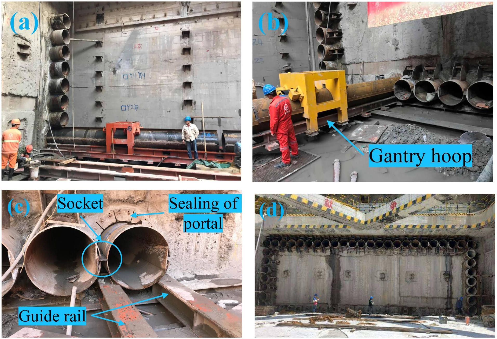
Pipe umbrella installation in the field ( 25 ): (a) jacking of the pipes on the right side, (b) gantry hoop for pipe end restraining, (c) jacking of the pipes on the downside, and (d) completion of the whole pipe umbrella.
Box Jacking Process
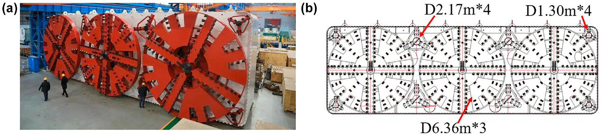
The underpass tunnel spans 87.6 m and is divided longitudinally into five segments, where the first segment measures 12.4 m and the remaining four segments are 18.8 m each. A full-face EPB shield is fitted to the first tunnel segment (see Figure 29) for soil excavation. This shield is equipped with twelve cutter wheels, consisting of three large cutter wheels and eight smaller ones (refer to Figure 29b), and four screw conveyors. Table 3 provides the system parameters of the EPB shield. During normal operations, the advance speed is set to approximately 20 and 30 mm per minute. To minimize friction resistance on the exterior of the tunnel, bentonite slurry is continuously injected at the interface between the tunnel and the soil through prefabricated holes in the tunnel segments. Once the entire box jacking process is completed, the lubricating bentonite slurry is further replaced by cementitious grouting injected between the pipe umbrella and the tunnel’s external boundary, which helps to minimize any potential secondary ground settlement that may occur afterward.
Equipment parameters of the earth pressure balanced (EPB) shield
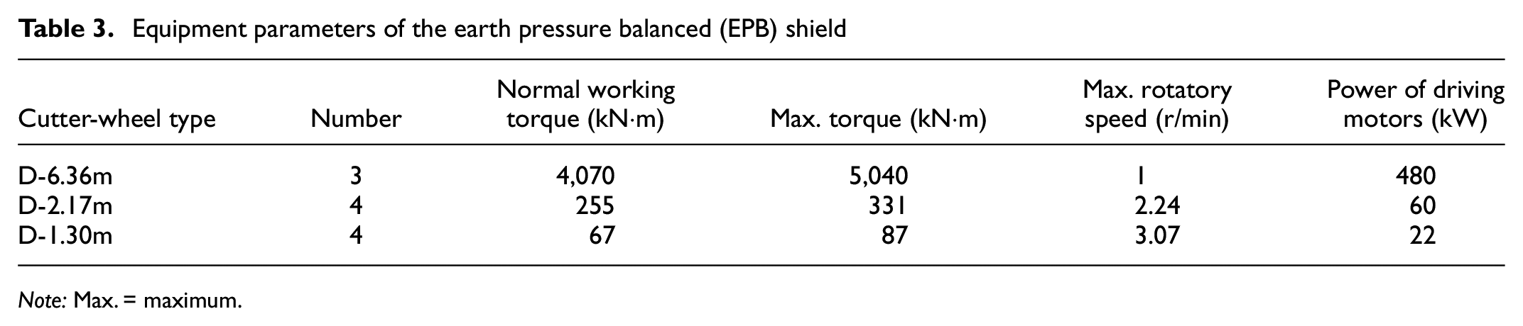
Note: Max. = maximum.
During the box jacking process, the vertical deformation of various pipes was monitored. Figure 30 illustrates the deformation of Pipe 7 (refer to the pipe numbered 7 in Figure 26) throughout the jacking of the first and second tunnel segments. The jacking of the first segment lasted for a period of 10 days, covering a length of 12.4 m. The deformation of the pipe during this period is depicted in Figure 30a. From the graph, it can be seen that the most significant deformation along the pipe axis occurs at three specific monitoring points, namely 1 m, 10 m, and 19 m (ahead of the launch shaft) in the direction of jacking. The heave measured at a location 10 m ahead of the launch shaft exhibits a steep increase, reaching a peak value of approximately 20 mm within the first 7 days. Subsequently, it starts to gradually decrease, stabilizing at around 13 mm by the tenth day ( 16 ).
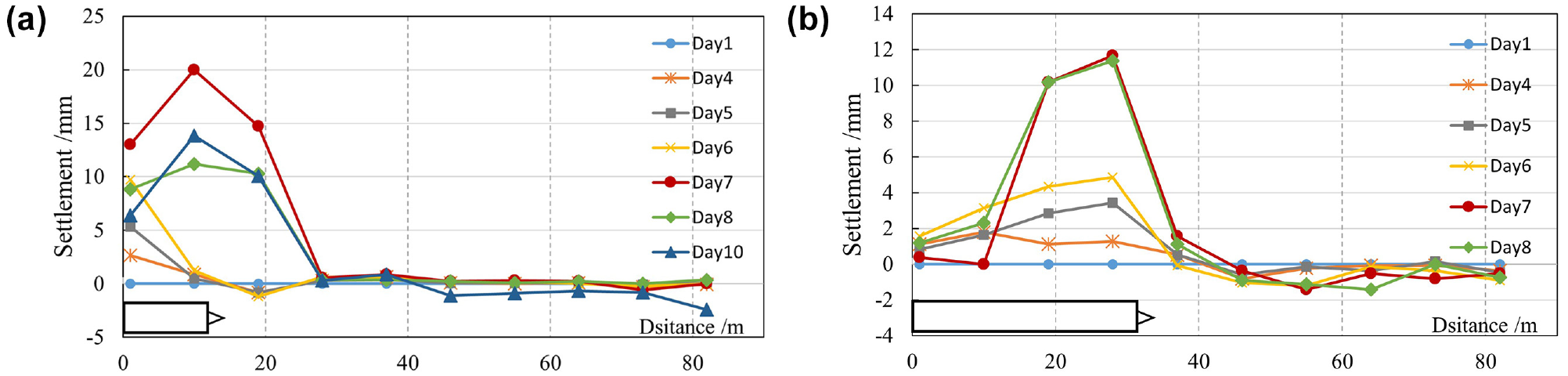
Pipe deformation during the (a) first and (b) second segment jacking (x-axis is the distance from the launch shaft) ( 16 ).
The jacking of the second segment in the project lasted for a total of 8 days, with a jacking length of 18.8 m. Figure 30b shows that there was minimal deformation in the section within 10 m distance to the launch shaft. However, the section between 10 and 40 m from the shaft experienced significant heave during the jacking process. The maximum heave, reaching about 13 mm, occurred 28 m ahead of the launch shaft on the eighth day. Field measurements conducted during the project indicated that ground heaves, rather than settlement, occur during the box jacking process. This was caused by two primary factors: first, the earth pressure in the soil chamber of the EPB shield was set slightly higher than the estimated static earth pressure at the face, resulting in a squeezing force on the excavation face and triggering ground heave; second, the pressured lubrication injection, particularly the grouting on the top side of the exterior tunnel boundary, exerted an uplifting force on the pipes at the top, further contributing to ground heave. However, according to the field construction observations, the ground heave that occurred during the box jacking process recovered slowly after the jacking was completed, and at some points the heave ultimately transformed into settlement deformation. After the entire tunnel box was jacked, the majority of monitoring points showed surface deformations (absolute heave/settlement) within a range of 20 mm. Only a few monitoring locations recorded settlement deformations of around 30 mm, which deforms the roadway pavement. However, the impact on traffic was limited, and there was no need for a complete or partial closure of the Middle-Ring Expressway. In conclusion, the pipe-umbrella box jacking method proved to be an effective method for constructing large box tunnels with shallow burial depths in soft ground, and this method allowed for the construction to proceed without pausing or disrupting existing surface infrastructure.
Discussion
Based on the aforementioned case studies, the primary technical functions of the pipe umbrella in large cross-section box jacking tunneling can be summarized initially as follows ( 21 ): ground pre-support, groundwater barrier, and face stability maintenance. Specifically, the pipe umbrella provides pre-support to the ground above the tunnel, helping to mitigate ground deformation during box jacking. Besides, the pipe umbrella encloses the tunnel boundary, creating a waterproof barrier to prevent groundwater inrush. Additionally, the pipe array on the roof acts similarly to a horizontal slab with flexural stiffness, supporting the upper ground and reducing the earth pressure at the excavation face. Figure 31, a and b, illustrates the face pressure with and without the pipe umbrella, respectively. It can be found that the pipe umbrella supports the upper ground and compromises part of the horizontal earth pressure, further reducing the earth pressure level (in the soil chamber of the shield) required for face stability, which is especially helpful in the operation of an open-face SGE shield. Furthermore, despite the event of large ground settlement in the first case study using an open-face shield which is attributable to improper excavation mode (see Figure 32a), the face collapse was not observed. However, without the pipe umbrella, a full-face collapse could have occurred in this scenario and the failure envelope could have extended to the ground surface ( 27 ) as shown in Figure 32b. Therefore, it is reasonable to conclude that the pipe umbrella could mitigate the risk of full-face collapse for box jacking in shallow depth.
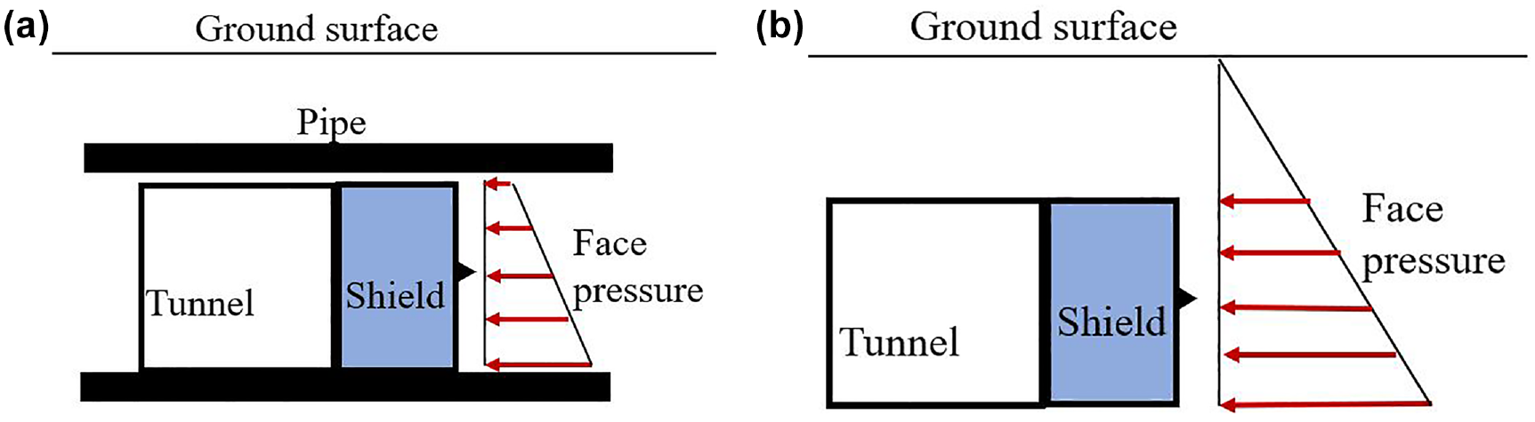
Earth pressure distribution at the excavating face (a) with and (b) without pipe umbrella.
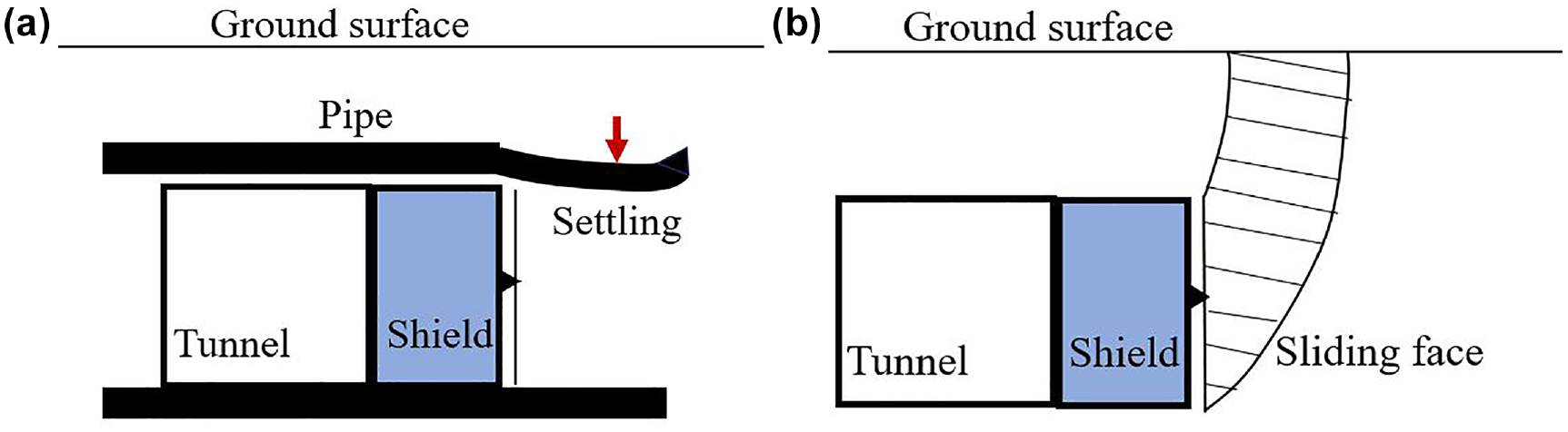
Face deformation (a) with and (b) without pipe-umbrella structure.
Furthermore, during the box jacking the pipe umbrella serves as a buffering against ground drag and helps control box jacking posture. It is important to note that the interface friction between the box tunnel and the surrounding ground could drag the vicinity ground forward, resulting in excessive horizontal ground deformation ( 14 ). When installed properly, the pipe umbrella isolates the tunnel from the surrounding soil and reduces horizontal drag forces on the tunnel’s circumference. Finally, when implementing box jacking in soft ground, the self-weight of the concrete segments and shield tends to cause a settling tendency in the jacking trajectory (see Figure 33a). The pipe umbrella encloses the tunnel segments and serves as a “sliding channel” that offers circumferential constraints to the jacking trajectory, and this can mitigate potential deviations along both horizontal and vertical directions, contributing to an easier posture controlling process.
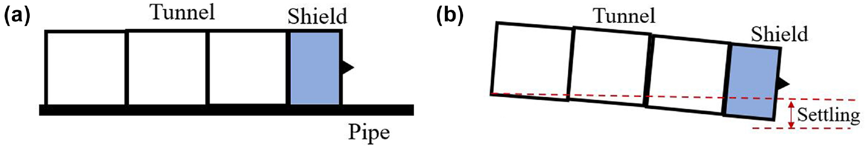
Vertical deviation in box jacking (a) with and (b) without pipe umbrella.
Although the two case studies showed the suitability of this method for constructing shallow underpass tunnels in very soft ground, there are still technical challenges and lessons to be learned concerning pipe umbrella installation. Firstly, based on field experience, controlling pipe deviation within the desired thresholds is typically with difficulties. The jacking of closely placed pipes leads to significant ground disturbance and increases the difficulty of controlling deviation. For instance, during field construction, the maximum observed vertical and horizontal deviations reached approximately 11.05 cm and 8.6 cm, respectively, with local damage to the inter-pipe connection. Secondly, two types of inter-pipe connections were designed and used in the case studies, with varying pipe cross-section geometries as shown in Figure 34. Field experience reveals that the pipe type with an external socket is more advantageous than the one with an internal socket, because a complete circular cross-section provides higher torque resistance and helps prevent out-of-plane distortion.
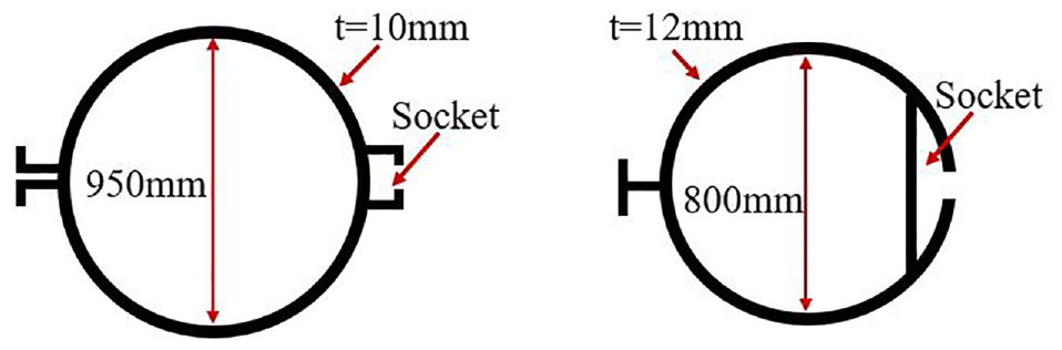
Illustration of pipe types used with external socket (left) and internal socket (right).
Based on the lessons learned from the case studies, several optimization measures can be proposed. Firstly, it is recommended to use pipes with a greater thickness than the current 10 mm and 12 mm used in the projects. A stiffer pipe can help mitigate torque and deflection deformation, ensuring higher jacking precision. Secondly, the inter-pipe connection design should consider the possibility of large spacing between adjoining pipes owing to deviations, and it is important to avoid total breakage of the inter-pipe connection. Thirdly, prefabricated grouting holes on the pipes are also recommended to allow for grouting execution in case of a large inter-pipe spacing or a broken inter-pipe connection. Moreover, it is crucial to set a proper gap between the pipe umbrella and the tunnel boundary. This gap will prevent any space intrusion and should be determined based on the construction quality of the project contractor. Overall, implementing these optimization measures can improve the construction process of shallow underpass tunnels in soft ground and enhance the performance of the pipe umbrella installation.
In addition to the technical applicability of the pipe umbrella, it is important to discuss the soil excavation method used in box jacking. Both SGE shield and full-face EPB shield have been used in the box jacking tunnel constructions as shown in the case studies. Comparing the performance of the two methods based on field observations is meaningful because it allows for a detailed examination of their strengths and weaknesses in practical applications. By evaluating different aspects such as human-labor saving, ease of ground deformation control, operation for trajectory deviation correction, necessity of ground dewatering, and machinery cost, a comprehensive understanding can be gained to inform decision-making in future box jacking projects.
To begin with, one key factor to consider is human-labor saving. The use of backhoe excavators or hand-digging in an SGE shield typically requires significant human labor, whereas a full-face EPB shield reduces the need for manual excavation. Therefore, the EPB shield is superior as regards reducing human labor work. Another important aspect is the ease of ground deformation control. The case studies demonstrate that an EPB shield has a significant advantage over an SGE shield in controlling ground deformation. The advanced automated mechanical system in the EPB shield enables efficient control, whereas the expertise of manual work is essential for ground deformation control in an open-face SGE shield. The operation for trajectory deviation correction is another factor to consider. Both shield types have methods for correcting tilting on the horizontal plane, such as adjusting jacking forces or face excavation rates. However, the EPB shield has the additional advantage of being able to adjust the rotatory speed of the screw conveyor to change the earth pressure distribution in the face, facilitating trajectory deviation correction. The necessity of ground dewatering is also important to evaluate. In an open-face SGE shield, ground dewatering is required for safety owing to the possibility of water flow through the inter-pipe connection. In contrast, an EPB shield offers the controllable risk of local water flow even without dewatering, reducing the need for additional measures. Finally, the cost of machinery is a crucial consideration. An EPB shield is typically an order of magnitude more expensive than an SGE shield, which may compromise its advantages in project scheming. However, there is potential for the further boosting application of EPB shields in future box jacking projects by reducing one-time equipment investment through improved system compatibility with multiple tunnel projects and module manufacturing technologies, which enable the recycling and reuse of different modules or parts to create new EPB shields. Overall, comparing the performance of these two methods based on field observations provides valuable insights into their strengths and weaknesses, informing decision-making in future box jacking projects.
Conclusions
This study provides a detailed review of the important technical concerns related to the pipe-umbrella box jacking method for constructing large rectangular underpass tunnels in soft ground. Specifically, it focuses on three key technical issues: pipe umbrella installation, face excavation, and box jacking control. Moreover, the study delves into two notable box-jacking tunnel projects, namely the Beihong Road Underpass Tunnel and the Tianlin Road Underpass Tunnel, through in-depth case studies. The paper presents significant findings and insights that can serve as valuable technical references for future box-jacking tunneling endeavors. To summarize, the study concludes with five key points.
(1) The pipe umbrella consists of interconnected pipes that are strategically installed along the perimeter of the tunnel boundary. Its primary technical functions in box jacking include ground pre-support, groundwater barrier, face stability maintenance, buffering against ground drag, and box jacking posture control. What distinguishes the pipe-umbrella box jacking method in the construction of shallow underpass tunnels is its unique capability to operate without the requirement of closing surface infrastructures.
(2) The performance of the pipe umbrella is directly influenced by the control of pipe installation deviations. To ensure proper functioning, the design of inter-pipe connections must consider the anticipated spacing between adjacent pipes, accounting for potential deviations, to prevent any damage to the connections. It is advisable to use pipes with sufficient stiffness by selecting an appropriate thickness because this helps mitigate both torque and deflection deformations, ensuring high jacking precision. Lastly, it is important to establish an appropriate gap between the pipe umbrella and the tunnel boundary to prevent any potential space intrusion.
(3) Both open-face SGE shields and closed-face EPB shields are applicable for excavating soil in box jacking tunnels. In the case of SGE shields, it is crucial to consider the soil excavation modes, such as prior-excavation and squeeze-excavation modes, as they significantly affect ground deformation patterns. These modes need to be appropriately determined based on the specific construction conditions. Moreover, operating an SGE shield demands a higher level of expertise in controlling ground disturbance, but SGE shields are more cost-effective compared with EPB shields.
(4) An EPB shield offers a higher degree of mechanization and automation during soil excavation, which enhances its efficiency in controlling ground disturbance and correcting box-jacking deviations. Additionally, EPB shields shows superior resistance against potential risks associated with groundwater flow that may occur through the inter-pipe spacing.
(5) During the implementation of the pipe-umbrella box jacking method, lubrication grouting applied along the tunnel circumference serves multiple purposes. It effectively reduces friction resistance and plays a crucial role in controlling the vertical movement of the pipe umbrella, ultimately influencing ground deformation. Consequently, it is imperative to carefully determine the pressure of the lubrication grouting during the box jacking process to minimize any potential adverse impacts on the surrounding ground.
Footnotes
Acknowledgements
The authors extend their sincere gratitude to Mr. Jixiang Chen from Shanghai Municipal Engineering Design Institute (Group) Co., Ltd. for his valuable contributions and support in this work.
Author Contributions
The authors confirm contribution to the paper as follows: study conception and design: Xi Jiang, Yun Bai, Baoshan Huang; data collection: Xi Jiang, Xuehui Zhang; analysis and interpretation of results: Xi Jiang, Xuehui Zhang, Xiao Zhang; draft manuscript preparation: Xi Jiang, Xuehui Zhang, Luyuan Long. All authors reviewed the results and approved the final version of the manuscript.
Declaration of Conflicting Interests
The authors declared no potential conflicts of interest with respect to the research, authorship, and/or publication of this article.
Funding
The authors received no financial support for the research, authorship, and/or publication of this article.
Data Accessibility Statement
The relevant data in this study are available by contacting the first or the communication authors.