
Abstract
The Hawaii Department of Transportation (HDOT) utilizes the Hawaii Modified Delaware Retrofit Thrie-Beam Bridge Rail to safely redirect vehicles on bridges with elevated sidewalks. However, the crashworthiness of this bridge rail has not been investigated under current impact safety standards. This bridge rail consists of a 10-gauge thrie-beam rail supported by W6x25 steel posts spaced at 6 ft 3 in. on-center. The top-mounted posts are anchored to an elevated concrete sidewalk ranging in height from 6 in. to 9 in. The ends of the bridge rail are connected to thrie-beam approach guardrail transitions (AGTs), which were designed to safely transition from a more flexible W-beam guardrail to the stiffer thrie-beam bridge rail. The objective of this research was to evaluate the Hawaii Modified Delaware Retrofit Thrie-Beam Bridge Rail and its associated AGT through full-scale crash testing in accordance with AASHTO’s Manual for Assessing Safety Hardware (MASH) Test Level 3 (TL-3) safety criteria. Three crash tests were conducted on the bridge rail, including tests on both the 6 in.- and 9 in.-tall sidewalk configurations. Four crash tests were conducted on the AGT, two of which resulted in excessive occupant compartment deformations that required design modifications and retesting. This paper details the crash test evaluations of both the bridge rail and AGT, the modifications made to the AGT to satisfy MASH TL-3 safety criteria, and recommendations for implementation of the system.
In the 1990s, the Delaware Retrofit Bridge Railing was developed and successfully crash tested in accordance with the safety performance criteria of NCHRP Report 350 ( 1 , 2 ). The bridge railing was developed as a retrofit system for use on existing bridges containing elevated sidewalks and bridge railings that had become obsolete (i.e., older bridge railings that would not meet the current crash safety standards). The Delaware Retrofit Bridge Railing consisted of a 10-gauge thrie-beam rail supported by W6x15 posts spaced at 6 ft 3 in., on-center. The top-mounted posts were anchored to the elevated sidewalk using ¾ in. thick baseplates and a combination of two 1½ in. diameter anchor rods and two ⅝ in. diameter anchor rods. The face of the rail was positioned flush with the front of the 8 in.-tall, elevated sidewalk and the rail had a top mounting height of just under 32 in. A cross-section of the Delaware Retrofit Bridge Railing is shown in Figure 1.
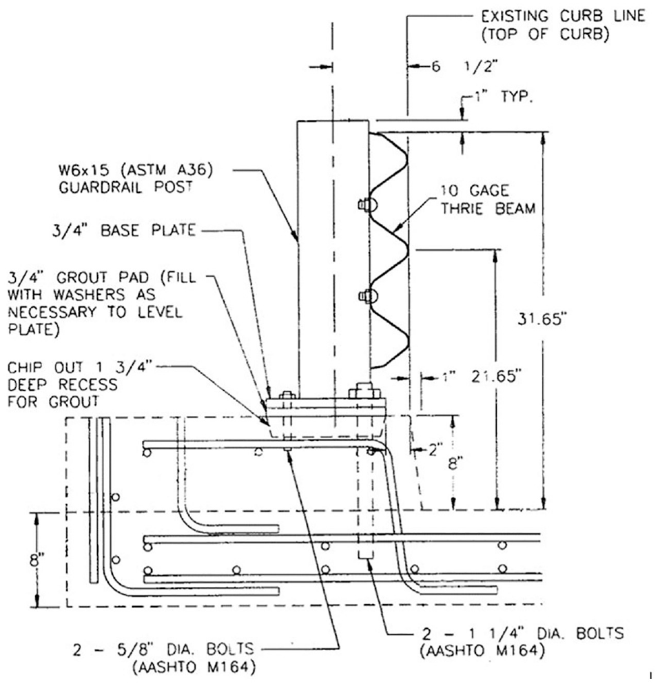
Details for the Delaware Retrofit Bridge Railing ( 1 ).
Since its initial development, multiple roadway agencies have made modifications to the Delaware Retrofit Bridge Railing to address the specific needs of their particular bridges. Thus, different versions of this retrofit bridge rail may utilize different rail heights, post sizes, curb/sidewalk heights, and anchorage, and/or incorporate blockouts. However, most of these design variations were not re-evaluated through crash testing, even as the crash standards were updated from NCHRP Report 350 criteria to AASHTO’s Manual for Assessing Safety Hardware (MASH) ( 3 ).
MASH, which was originally released in 2009 and had a second edition released in 2016, made significant changes to the crash testing impact conditions and the evaluation criteria. MASH increased the masses of all the test vehicles and increased the impact angle for the small car test vehicle. Thus, the impact severity of each test increased over the NCHRP Report 350 test conditions. MASH also specified occupant compartment deformation limits for different regions of the vehicle, whereas the NCHRP Report 350 only had a single deformation limit for the entire occupant compartment.
At the time of this project, only one version of these modified thrie-beam retrofit bridge railings was crash tested and evaluated to MASH safety criteria ( 4 ). This MASH-tested, thrie-beam retrofit bridge rail incorporated a top rail height of 34 in., a 3 in.-deep timber blockout, and a 6 in.-tall curb, as shown in Figure 2a. Further, this MASH-tested system was mounted directly to the top of the curb (i.e., no grout pad) and used four ⅞ in. diameter anchor rods. The posts remained W6x15 posts spaced at 37½ in. This configuration was subjected to both MASH test designation nos. 3-10 and 3-11 and was found to satisfy all the safety evaluation criteria of MASH Test Level 3 (TL-3).
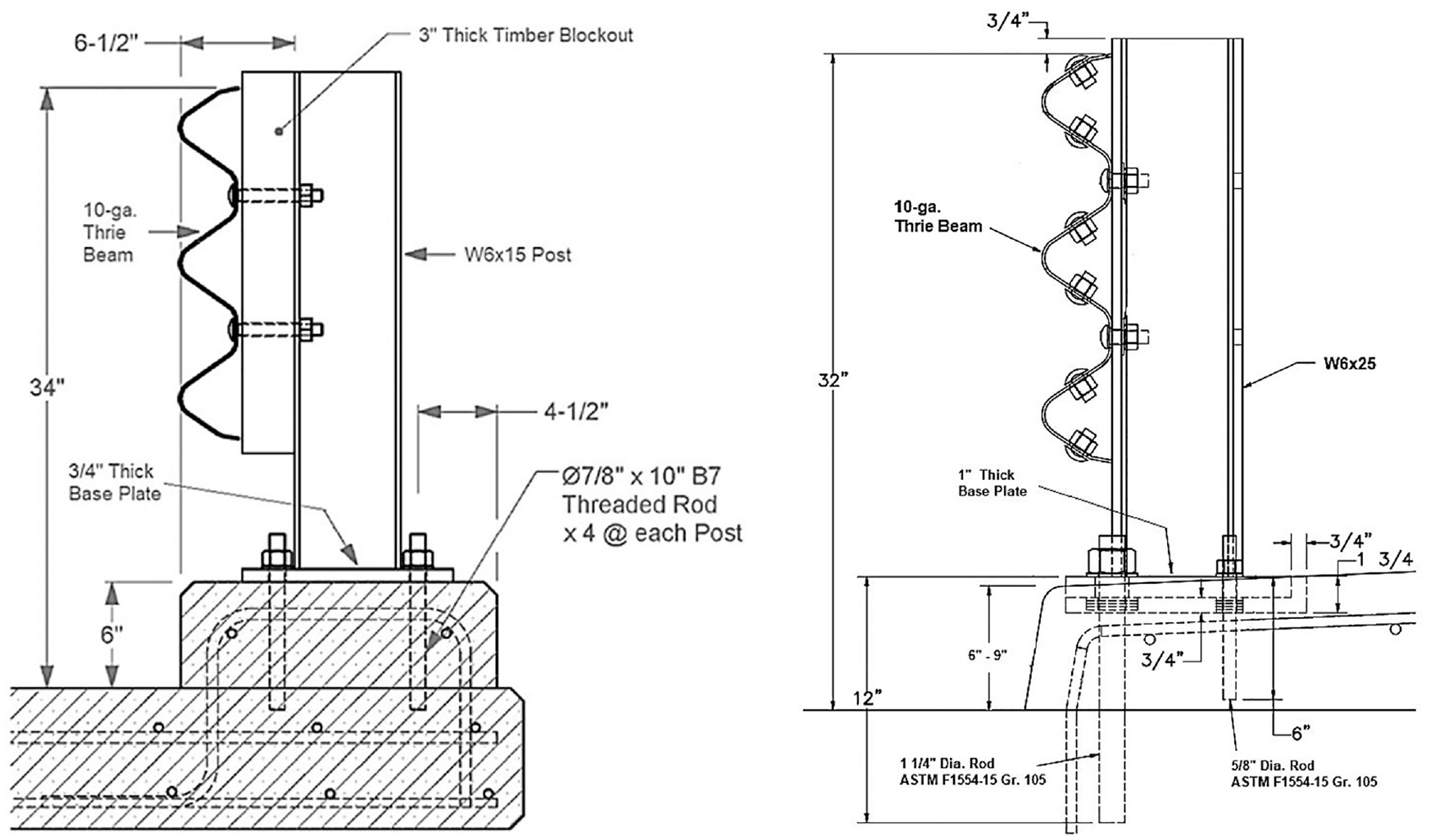
Details for (a) AASHTO’s Manual for Assessing Safety Hardware tested retrofit bridge railing ( 4 ), and (b) the Hawaii modified Delaware Retrofit Thrie-Beam Bridge Railing.
The Hawaii Department of Transportation (HDOT) utilizes a version of these thrie-beam railings called the Hawaii Modified Delaware Retrofit Thrie-Beam Bridge Railing. The HDOT railing is similar to the original Delaware railing with a 32 in. rail height, a 6 ft 3 in. post spacing, the use of a grout pad below the post, and the same 1½ in. diameter and ⅝ in. diameter anchor rods. The HDOT railing is unique in that it uses an increased post size, with a W6x25 instead of a W6x15. The height of the elevated sidewalk is also variable between 6 in. and 9 in., as shown in Figure 2b.
Because of the differences between the Hawaii Modified Delaware Retrofit Thrie-Beam Bridge Railing and the MASH-tested system, HDOT desired to evaluate their railing through crash testing. Specifically, there were concerns with vehicle snag on the larger posts and the strength of the anchor rods depending on the height of the elevated sidewalk. Thus, research efforts were undertaken to evaluate the safety performance of the Hawaii Modified Delaware Retrofit Thrie-Beam Bridge Railing according to MASH TL-3.
To ensure a safe bridge railing system, the ends of the railing need to be connected to an approach guardrail transition (AGT). AGTs are carefully designed guardrail systems that connect more flexible W-beam guardrail systems to stiff bridge railings. Although the various roadway agencies all used AGT configurations for their thrie-beam retrofit bridge railings, none of these AGTs had been crash tested or evaluated to MASH safety performance criteria. Recognizing this lack of testing and research, HDOT desired to conduct crash testing on both their retrofit bridge railing and the adjacent AGT to MASH TL-3 evaluation criteria.
HDOT previously conducted MASH crash testing on an AGT connecting the Midwest Guardrail System (MGS) to their vertical concrete bridge rail end post. This AGT incorporated a 31 in.-tall nested thrie-beam rail, W6x15 posts, and a 6 in.-tall, vertical curb located below the guardrail, as shown in Figure 3 ( 5 ). The upstream end of the AGT incorporated the MASH TL-3 crashworthy MGS upstream stiffness transition ( 6 , 7 ). The HDOT AGT to vertical concrete bridge rail was found to be crashworthy to MASH TL-3 safety performance criteria. HDOT desired to make small modifications to this AGT configuration such that it could be attached to the Hawaii Modified Delaware Retrofit Thrie-Beam Bridge Railing in hopes of creating a MASH TL-3 crashworthy AGT and completing the evaluation on the entire barrier system.
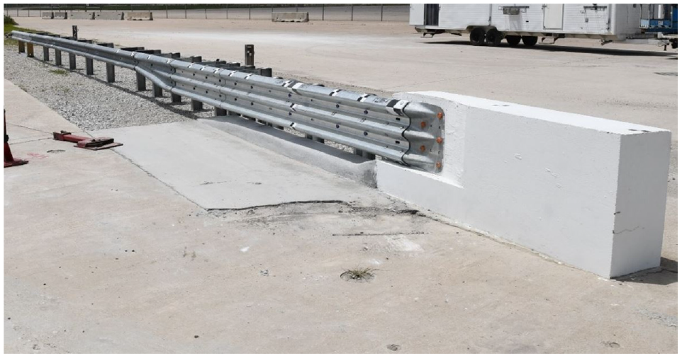
Hawaii Department of Transportation’s approach guardrail transition connecting Midwest Guardrail System to vertical concrete bridge rail end post ( 5 ).
Hawaii Modified Delaware Retrofit Thrie-Beam Bridge Railing Test Requirements
According to TL-3 of MASH, longitudinal barrier systems, such as bridge rails, must be subjected to two full-scale vehicle crash tests, MASH test designation nos. 3-10 and 3-11. MASH test designation no. 3-11 involves a 5,000 lb pickup truck (2270P) striking the barrier at 62 mph and an angle of 25°, while MASH test designation no. 3-10 incorporates a 2,400 lb small car (1100C) striking the barrier at 62 mph and 25°.
MASH test designation no. 3-11 involves the heavier vehicle, so it applies higher impact loads to the system. Thus, MASH test designation no. 3-11 was necessary to evaluate strength of the bridge rail, specifically its pocketing resistance and anchorage strength. If the guardrail deforms between posts, guardrail pocketing may occur and allow the vehicle to snag on the posts, which can lead to instability issues, excessive decelerations, or both. The size of the W6x25 posts made post deformations unlikely. Thus, the strength of the anchors would control the strength of the posts and the entire bridge railing. Recall that HDOT uses their retrofit bridge railing on curb/sidewalk heights ranging between 6 in. and 9 in., but the same length anchor rods are used regardless of sidewalk height. The shallow 6 in.-tall sidewalk would provide limited resistance to anchor breakout, so the anchor strength would be reliant on the anchor-in-deck breakout strength. Alternatively, the 9 in.-tall sidewalk would limit the anchor embedment depth into the deck, so the anchorage strength would be reliant on the breakout strength of the 9 in.-tall sidewalk. Since the anchors were located only a few inches from the front face of the sidewalk, it was difficult to determine which configuration would be more critical to the anchorage strength of the bridge railing. Therefore, MASH test designation no. 3-11 tests were performed with the railing mounted on both 6 in.- and 9 in.-tall sidewalks to bracket the behavior of the anchorage and the system as a whole.
MASH test designation no. 3-10 with the small car was critical in the evaluation of the front bumper and wheel wedging below the thrie-beam rail and snagging on the bridge rail posts. Since the bridge railing is always installed with a 32 in. rail height relative to the roadway surface, the 6 in.-tall curb would provide a larger opening between the curb and the bottom of the rail through which the vehicle could extend. Thus, MASH test designation no. 3-10 was deemed more critical with the bridge railing installed on a 6 in.-tall sidewalk. Pending a successful test with the bridge railing installed on a 6 in.-tall sidewalk, then the system would be believed to also perform satisfactorily when installed on a 9 in.-tall sidewalk.
Therefore, the Hawaii Modified Delaware Retrofit Thrie-Beam Bridge Railing was subjected to two MASH 3-11 tests with the railing installed on both a 6 in.- and 9 in.-tall sidewalks, and one MASH 3-10 with the railing installed on a 6 in.-tall sidewalk. The critical impact points (CIPs) for these tests were selected using the calculated railing and post strengths, Fp and Mp, respectively, in conjunction with the CIP plots found in Section 2.3.2.1 of MASH.
Bridge Railing Test Installation Details
Crash testing of the Hawaii Modified Delaware Retrofit Thrie-Beam Bridge Rail was conducted on two test articles. The first incorporated a 9 in.-tall sidewalk while the second incorporated a 6 in.-tall sidewalk. The bridge railings in both test installations were nearly identical, except for the height of the sidewalk. The test installation with a 9 in.-tall sidewalk had an AGT, MGS installation, and W-beam anchorage system attached to its upstream end. This installation was later used for the full-scale crash testing of the AGT. The downstream end of the installation on a 9 in.-tall sidewalk was anchored with a thrie-beam anchorage system designed to maintain rail tension. The thrie-beam anchorage system was used to anchor both ends of the second test installation mounted on the 6 in.-tall sidewalk. Both test installations mounted to the 9 in.-tall sidewalk and the 6 in.-tall sidewalk are shown in Figures 4 and 5, respectively.
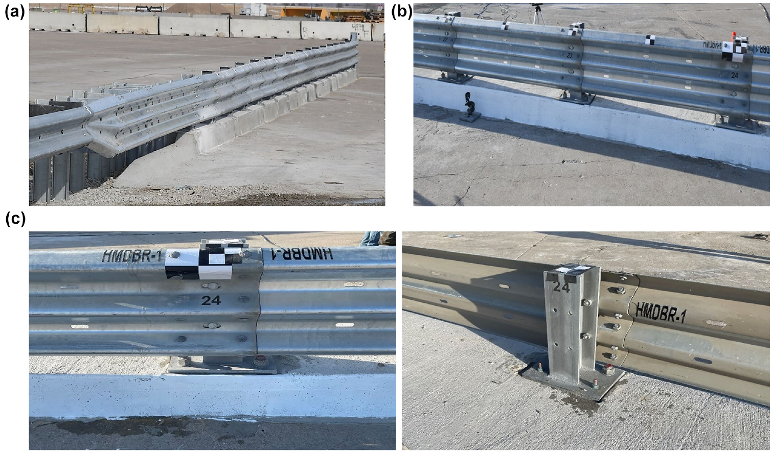
Hawaii Modified Delaware Retrofit Thrie-Beam Bridge Railing on 9 in.-tall sidewalk: (a) full installation, (b) front-side view, and (c) bridge rail post installation.
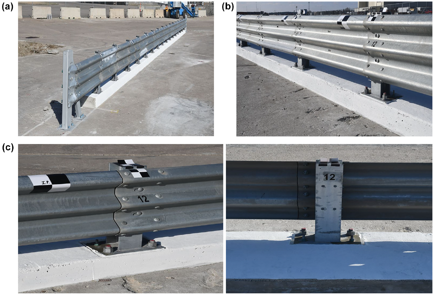
Hawaii Modified Delaware Retrofit Thrie-Beam Bridge Railing on 6 in.-tall sidewalk: (a) full installation, (b) front-side view, and (c) bridge rail post installation.
Both test installations of the Hawaii Modified Delaware Retrofit Thrie-Beam Bridge Rail consisted of a 10-gauge thrie-beam rail with a top height of 32 in. above the roadway surface. The rails were supported by W6x25 steel posts spaced at 75 in. The W6x25 steel posts were welded to 16 in.-long × 11 in.-wide × 1 in.-thick ASTM A36 steel base plates. The base plates were countersunk into the top of the sidewalk, and the gap remaining under the base plate and around the edges was backfilled with an epoxy grout following the specifications of ASTM C881, Type IV, Grade I, Class C epoxy filler. The base plates were secured to the sidewalk using two 1½ in.-diameter, 14 in.-long anchor rods at the traffic side (front side) of the base plate and two ⅝ in.-diameter, 8 in.-long anchor rods at the non-traffic side (back side) of the base plate. All anchor rods were epoxied into drilled holes in the concrete sidewalks. The front anchor rods extended 2½ in. and 5½ in. into the concrete tarmac for the 9 in. sidewalk and the 6 in. sidewalk, respectively.
The thrie-beam rail splices located at the post installation utilized ⅝ in.-diameter by 1½ in.-long guardrail bolts with heavy hex nuts and plain washers. The thrie-beam rail sections were attached to the posts using two ⅝ in.-diameter by 2 in.-long guardrail bolts with heavy hex nuts and plain washers.
Both sidewalk installations were 3 ft wide, and the top surfaces of the sidewalks were sloped at 1V:24H toward the traffic-side face. The sidewalks were composed of concrete with a minimum compressive strength of 4,000 psi and a combination of transverse and longitudinal ASTM A615 Grade 60 rebar. The sidewalk reinforcement consisted of three no. 4 longitudinal bars that were vertically spaced 12 in. apart. The sidewalk transverse reinforcement was vertical no. 4 stirrups spaced at 12 in. on the center and were epoxied into the tarmac below the sidewalk.
The thrie-beam end anchor assembly consisted of a vertical HSS6x12x½ steel tube, an HSS6x4x⅝ steel tube angled at 55° to the ground, and a 10-gauge thrie-beam terminal connector. This thrie-beam downstream end anchorage was successfully crash tested and reported in a previous project ( 8 ). The upstream end of the bridge rail was connected to the HDOT thrie-beam AGT system, which is described in the following sections.
Bridge Railing Full-Scale Crash Testing
Test HMDBR-1 (MASH Test 3-11, 9 in. Sidewalk)
Test HMDBR-1 was conducted according to MASH test 3-11 on the Hawaii Modified Delaware Retrofit Thrie-Beam Bridge Rail mounted on a 9 in.-tall sidewalk. The 5,001 lb pickup truck struck the bridge rail at a speed of 63.1 mph and an angle of 25.5°. The impact occurred 75.1 in. upstream from the centerline of post 25, and the impact severity was 123.4 kip-ft. During the test, the front anchors of post 24 broke out of the concrete sidewalk and underlying tarmac, which allowed increased system deflections and rail pocketing compared with the other tests. The maximum dynamic deflection of the system was measured to be 10.2 in. However, the vehicle was contained and smoothly redirected with moderate damage to both the barrier system and the vehicle, as shown in Figure 6. The vehicle exited the system at a speed of 42.2 mph and an angle of −11.1°. All occupant risk values and occupant compartment deformations fell within the recommended safety limits established in MASH, as shown in Table 1. Therefore, test HMDBR-1 was successful according to the safety criteria of MASH test 3-11.
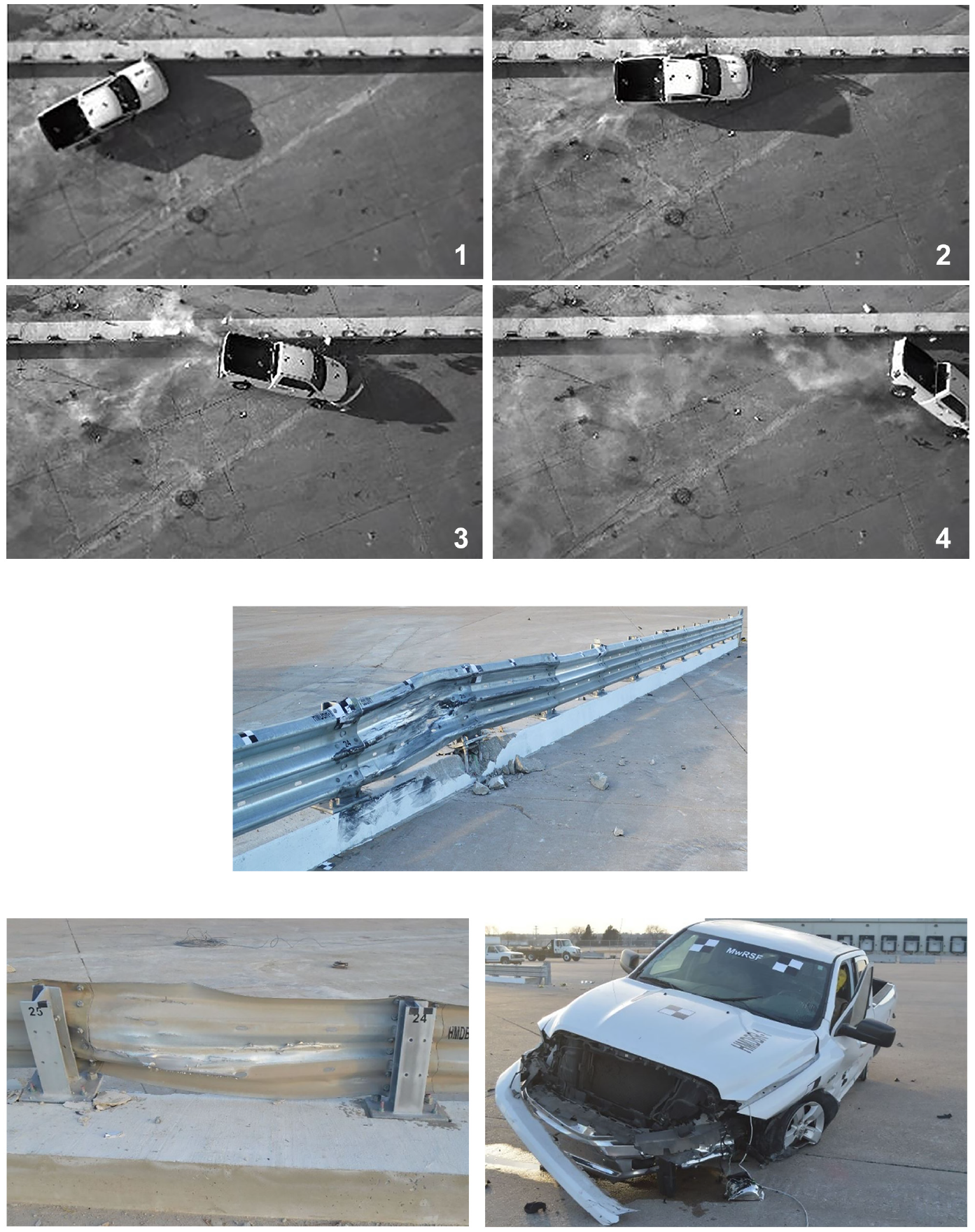
Test HMDBR-1: sequential photographs, barrier damage, and vehicle damage.
Crash Testing Summary for Hawaii Modified Delaware Retrofit Thrie-Beam Bridge Railing
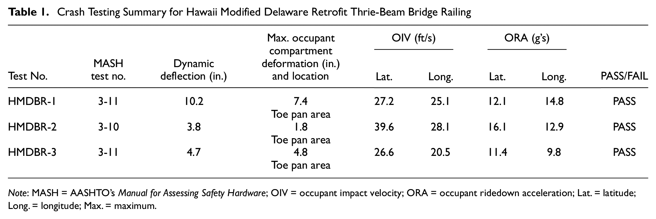
Note: MASH = AASHTO’s Manual for Assessing Safety Hardware; OIV = occupant impact velocity; ORA = occupant ridedown acceleration; Lat. = latitude; Long. = longitude; Max. = maximum.
Test HMDBR-2 (MASH Test 3-10, 6 in. Sidewalk)
Test HMDBR-2 was conducted according to MASH test 3-10 on the Hawaii Modified Delaware Retrofit Thrie-Beam Bridge Rail mounted on a 6 in.-tall sidewalk. The 2,453 lb small car struck the bridge rail at a speed of 62.7 mph and an angle of 24.6°. The impact occurred 60.4 in. upstream from post 13, and the impact severity was 55.9 kip-ft. The vehicle was successfully contained and smoothly redirected with minimal damage to the barrier system and moderate damage to the vehicle, as shown in Figure 7. The vehicle exited the system at a speed of 43.8 mph and an angle of −11.9°. All occupant risk values and occupant compartment deformations fell within the recommended safety limits established in MASH, as shown in Table 1. Therefore, test HMDBR-2 was successful according to the safety criteria of MASH test 3-10.
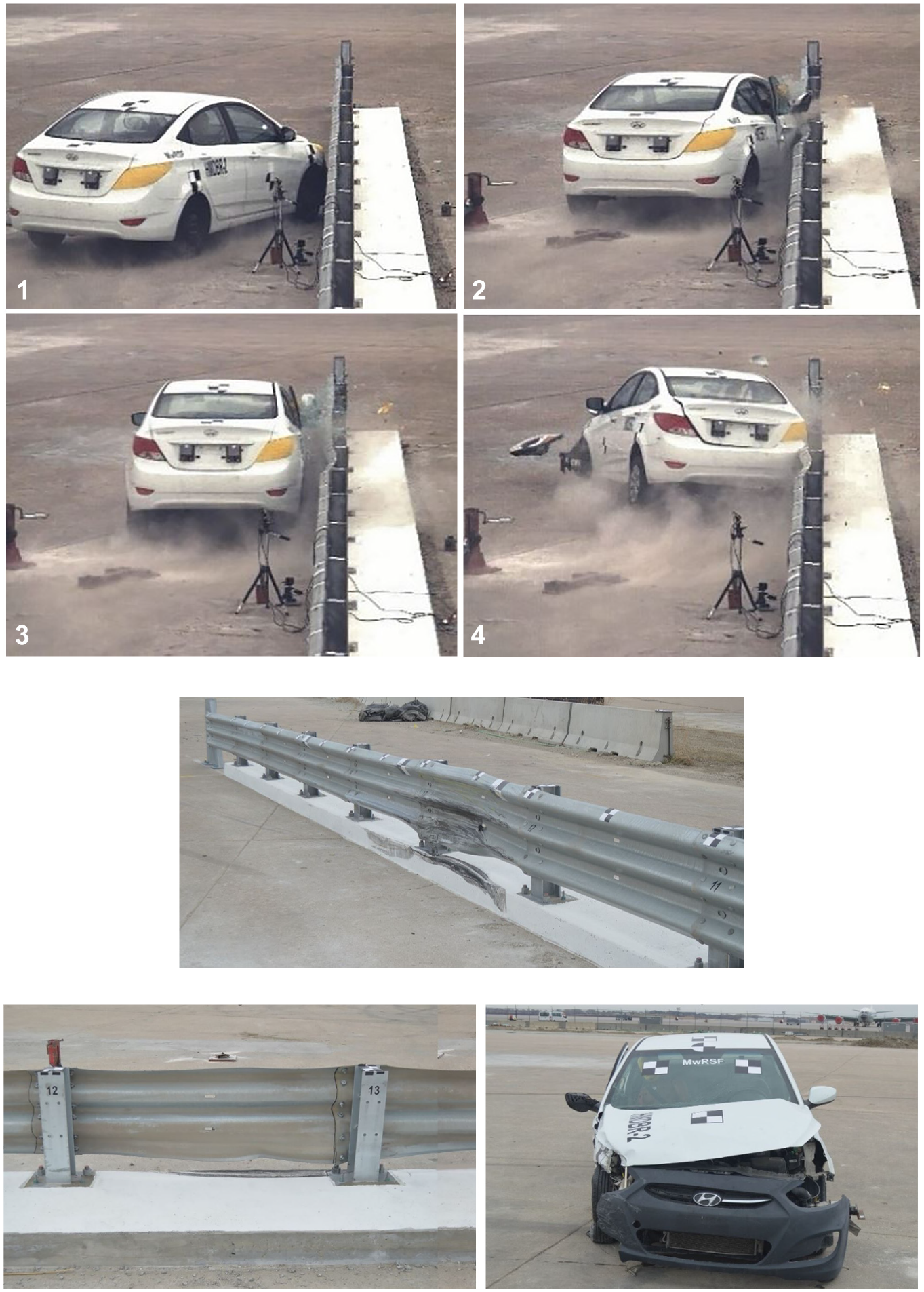
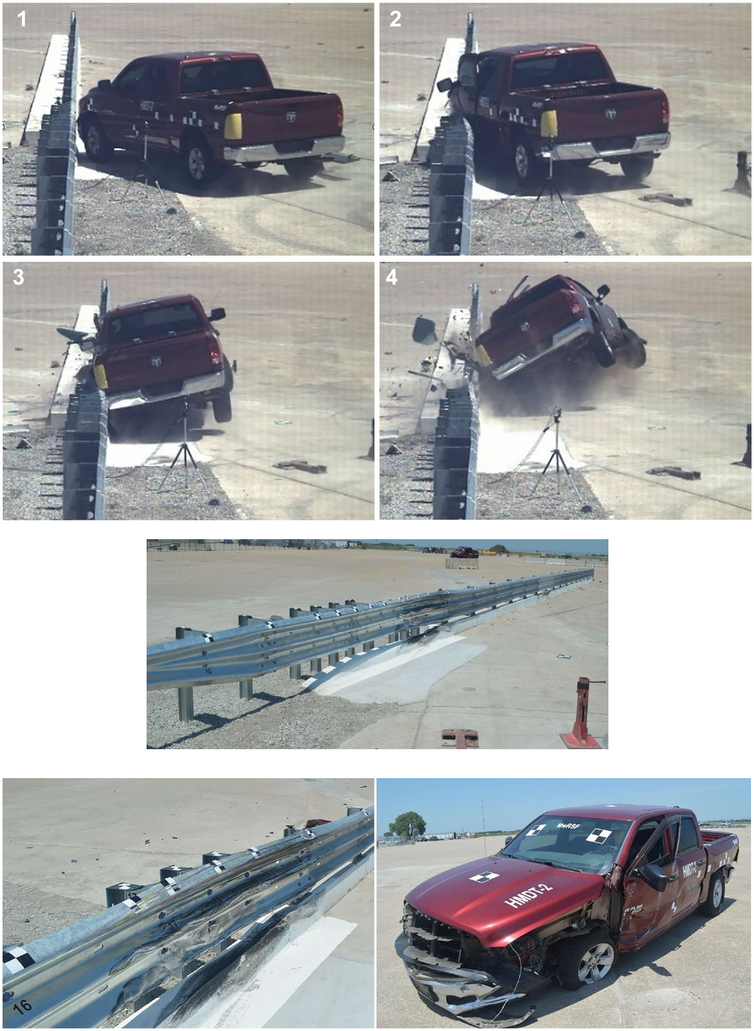
Test HMDBR-2: sequential photographs, barrier damage, and vehicle damage.
Test HMDBR-3 (MASH Test 3-11, 6 in. Sidewalk)
Test HMDBR-3 was conducted according to MASH test 3-11 on the Hawaii Modified Delaware Retrofit Thrie-Beam Bridge Rail mounted on a 6 in.-tall sidewalk. The 5,001 lb pickup truck struck the bridge rail at a speed of 63.3 mph and an angle of 25.5°. The impact occurred 80.5 in. upstream from post no. 7, and the impact severity was 124.2 kip-ft. The vehicle was successfully contained and smoothly redirected with minimal damage to the barrier system and moderate damage to the vehicle, as shown in Figure 8. The vehicle exited the system at a speed of 45.1 mph and an angle of −6.8°. All occupant risk values and occupant compartment deformations fell within the recommended safety limits established in MASH, as shown in Table 1. Therefore, test HMDBR-3 was successful according to the safety criteria of MASH test 3-11.
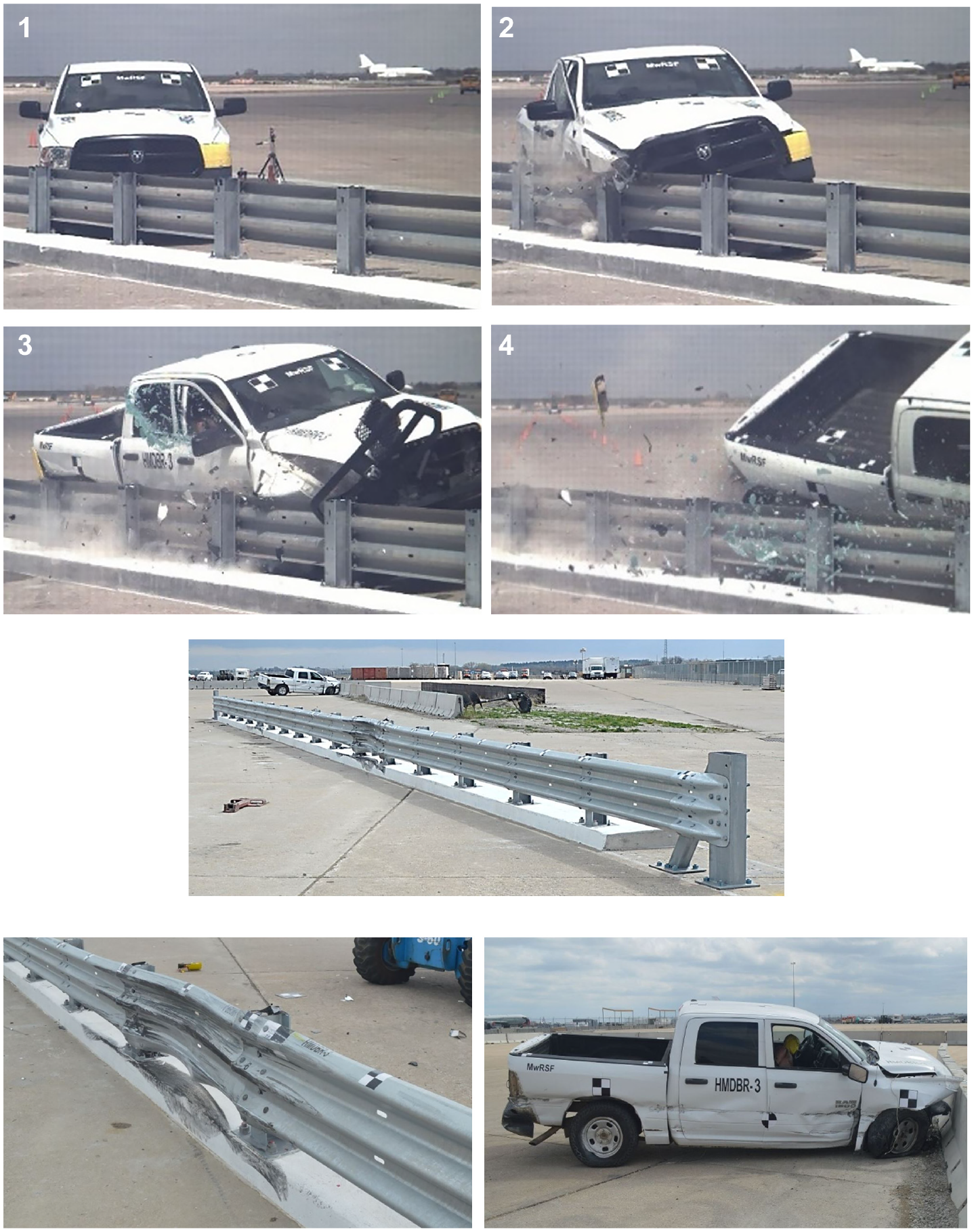
Test HMDBR-3: sequential photographs, barrier damage, and vehicle damage.
Summary and Discussion—Bridge Rail
Three full-scale crash tests were conducted to evaluate the safety performance of the Hawaii Modified Delaware Retrofit Thrie-Beam Bridge Railing. All three tests satisfied MASH TL-3 safety performance criteria. MASH test 3-11 was conducted on the bridge rail installed on both 6 in.- and 9 in.-tall sidewalks. The front anchors of one post on the 9 in.-tall sidewalk broke through the sidewalk and pulled out of the underlying tarmac, while none of the anchors in the 6 in.-tall sidewalk pulled out. Thus, the critical anchorage strength was observed to be associated to the installation on a 9 in.-tall sidewalk. The anchor pullout allowed increased system deflections and increased damage to the system, but the bridge railing still contained and safely redirected the vehicle which struck it. Thus, the bridge railing demonstrated adequate strength installed on both 6 in.- and 9 in.-tall sidewalks.
MASH test 3-10 was successfully conducted on the bridge railing mounted on a 6 in.-tall sidewalk, which maximized the risk of the small car extending under the thrie-beam rail and snagging on a post. Since this test was successful, MASH test 3-10 with the railing installed on a 9 in-tall sidewalk was deemed non-critical as the taller curb would only reduce the gap between the thrie-beam rail and the sidewalk, thereby reducing the risk of vehicle snag. Therefore, the Hawaii Modified Delaware Retrofit Thrie-Beam Bridge Railing was found to be MASH TL-3 crashworthy when installed on elevated concrete sidewalks with a height ranging between 6 in. and 9 in.
Hawaii Modified AGT Test Requirements
MASH TL-3 evaluation of longitudinal barrier transitions, such as an AGT, involves two full-scale vehicle crash tests, MASH tests 3-20 and 3-21. MASH test 3-20 incorporates the 1100C small car striking the barrier at 62 mph and an angle of 25°, while MASH test 3-21 involves the 2270P pickup truck striking the barrier at 62 mph and 25°.
Recent testing of AGTs has illustrated the importance of evaluating two different transition regions along the length of the AGT: 1) the downstream transition where the thrie-beam rail connects to the bridge rail, and 2) the upstream stiffness transition where the W-beam guardrail transitions to a stiffer thrie-beam barrier. The upstream stiffness transition of HDOT’s AGT was specifically designed to replicate the MASH TL-3 crashworthy MGS upstream stiffness transition ( 5 – 7 ). Therefore, crash testing of the upstream stiffness transition was deemed non-critical and only MASH tests 3-20 and 3-21 on the downstream end of the AGT were necessary to evaluate the system.
Vehicle contact and snagging on rigid bridge rail components is one of the main safety concerns with AGTs. Vehicle snag on the bridge rail posts was not observed to be an issue during the crash tests on the bridge rail test installations. However, wheel snag on the upstream end of the elevated sidewalk remained a potential snag risk. Thus, attachment of the AGT to the bridge railing mounted on the tallest (9 in.) elevated sidewalk was determined to be the critical installation configuration to evaluate wheel snag potential.
Similar to the bridge rail evaluation, the CIPs for the evaluation of the AGT were selected using the calculated plastic moment of rail (Mp) and post yield force per unit length of barrier (Fp) in conjunction with the CIP plots found in Section 2.3.2.1 of MASH.
Preliminary HDOT AGT System Details
The preliminary design configuration for HDOT’s AGT to the Hawaii Modified Delaware Retrofit Thrie-Beam Bridge Railing was adapted from HDOT’s MASH TL-3 crashworthy AGT to vertical concrete bridge rail ( 5 ). The AGT consisted of 12.5 ft of nested 12-gauge thrie-beam rail supported by 6.5 ft-long W6x15 posts spaced at 37.5 in. on-center. Upstream of the nested thrie-beam rail was the MGS upstream stiffness transition which consisted of 6.25 ft of 12-gauge thrie-beam rail, the 10-gauge asymmetrical W-to-Thrie transition segment, and W-beam guardrail ( 6 , 7 ). The MGS upstream stiffness transition and the MGS used 6 ft-long W6x8.5 posts at various spacings. Blockouts within the AGT consisted of rectangular HSS steel tubes. Blockouts on the W6x15 posts were 8 in.-deep HSS 8x6x½ sections, while blockouts on the W6x8.5 posts were 12 in.-deep HSS 12x4x½ sections. The MGS extended 50 ft upstream from the AGT and was anchored using an MGS trailing end anchor system, which has been MASH TL-3 crash tested ( 9 – 12 ).
The downstream end of the AGT was directly connected to the Hawaii Modified Delaware Thrie-Beam Bridge Railing. The first 10-gauge bridge rail segment was sandwiched between the nested 12-gauge thrie-beam segments of the AGT, and the splice between these three rail segments was centered on the first bridge rail post. Note the MGS has a nominal rail height of 31 in., while the bridge railing has a nominal height of 32 in. Thus, the rail height was gradually transitioned from 31 in. to 32 in. over a length of 18¾ ft beginning at the downstream end of the W-to-thrie transition segment and ending at the downstream end of the AGT (or the first bridge rail post).
A 6 in.-tall concrete curb was located below the AGT with its front face aligned with the face of the guardrail. The face of the near vertical curb was tapered with a slope of 6V:1H. The curb began 37.5 in. downstream from the W-to-thrie transition segment and tapered up to its nominal height of 6 in. over the first 3 ft of longitudinal curb distance. To mitigate wheel snag on the elevated sidewalk, the curb below the AGT was tapered upward 3 in. over 9 in. of longitudinal length at the downstream end such that the curb height matched the 9 in. height of the elevated sidewalk. Photographs of the preliminary design test installation are shown in Figure 9. Note, this preliminary AGT design was only evaluated in test HMDT-1. The AGT was then modified before additional testing.
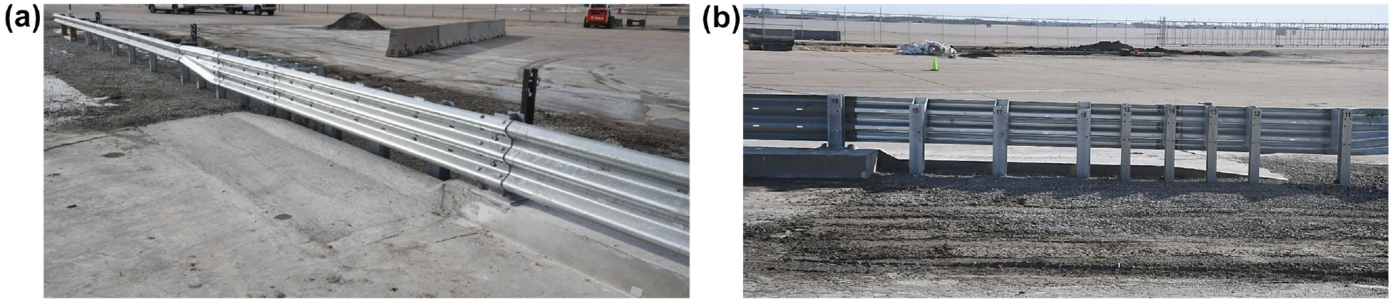
Photographs of preliminary approach guardrail transition to Hawaii Modified Delaware Retrofit Thrie-Beam Bridge Railing: (a) traffic side view, and (b) non-traffic side view.
Full-Scale Crash Testing
Test HMDT-1 (MASH Test 3-21)
Test HMDT-1 was conducted according to MASH test 3-21 on the preliminary HDOT AGT to the Hawaii Modified Delaware Retrofit Thrie-Beam Bridge Railing mounted on a 9 in.-tall elevated sidewalk. The 5,029 lb pickup truck struck the AGT at a speed of 61.7 mph and an angle of 25.7° at a location 84.6 in. upstream from post 19, the first bridge rail post. The resulting impact severity was 116.9 kip-ft. The vehicle was contained and redirected with moderate damage to the barrier system and the vehicle, as shown in Figure 10. All vehicle occupant risk values fell within the MASH recommended safety limits. However, as the vehicle approached the first bridge rail post, lateral system deflections allowed the front wheel to climb over the curb and up the vertical taper adjacent to the elevated sidewalk. Additionally, the wheel was pushed backward as the guardrail formed a small pocket in front of the near-rigid bridge post. These combined vertical and longitudinal wheel motions pushed the wheel toward the occupant compartment causing 10.5 in. of deformation to the toe pan, which exceeded the MASH deformation limit of 9 in. Therefore, test HMDT-1 failed to meet the safety performance criteria specified for MASH test 3-21.
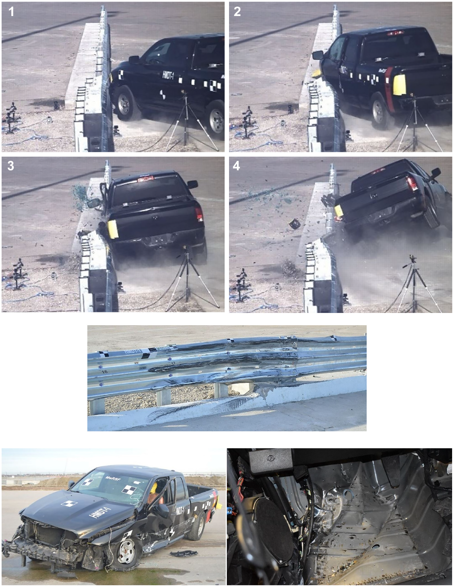
Test HMDT-1: sequential photographs, barrier damage, and vehicle damage.
Following the failure of test HMDT-1, two design modifications were incorporated into the AGT to mitigate the wheel snag and excessive toe pan deformations. First, the vertical slope for the concrete curb adjacent to the elevated sidewalk was flattened from 3H:1V to 6H:1V to potentially mitigate wheel snag. Thus, the curb taper now measured 3 in. vertically by 18 in. longitudinally. Second, an additional W6x15 transition post was added to stiffen the downstream end of the AGT to potentially reduce system deflections and guardrail pocketing. The presence of the elevated sidewalk prevented the additional post from being placed between the first bridge rail post and the last transition post, so the additional post was placed between the two most downstream posts from the previous AGT configuration. Thus, the W6x15 transition posts at the downstream end of the AGT were now spaced at 18¾ in. on-center. The modified AGT system, as shown in Figure 11, was utilized in the next two crash tests, tests HMDT-2 and HMDT-3.
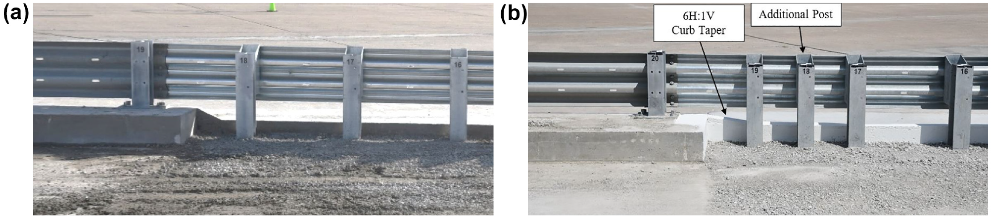
(a) Original, and (b) modified approach guardrail transition test installation: test nos. HMDT-2 and HMDT-3.
Test HMDT-2 (MASH Test 3-21)
Test HMDT-2 was conducted according to MASH test 3-21 on the modified HDOT AGT to the Hawaii Modified Delaware Retrofit Thrie-Beam Bridge Railing mounted on a 9 in.-tall elevated sidewalk. The 4,981 lb pickup truck struck the modified AGT at a speed of 62.5 mph and an angle of 24.5° at a location 78.5 in. upstream from post no. 20, which is the first bridge post. The resulting impact severity was 114.4 kip-ft. The vehicle was successfully contained and smoothly redirected with moderate damage to the barrier system and the test vehicle, as shown in Figure 12. After striking the barrier system, the vehicle exited the system at a speed of 47.3 mph and an angle of −6.8°. All occupant risk values fell within the MASH recommended limits. The maximum toe pan deformation of 7.5 in. satisfied the MASH allowable limit of 9 in. Therefore, test HMDT-2 was determined to satisfy the safety performance criteria specified for MASH test 3-21.
Test HMDT-2: sequential photographs, barrier damage, and vehicle damage.
Test HMDT-3 (MASH Test 3-20)
Test HMDT-3 was conducted according to MASH test 3-20 on the modified HDOT AGT to the Hawaii Modified Delaware Retrofit Thrie-Beam Bridge Railing mounted on a 9 in.-tall elevated sidewalk. The 2,430 lb small car struck the modified AGT at a speed of 62.3 mph and an angle of 25.0° at a location 54.7 in. upstream from post no. 20, the first bridge rail post. The resulting impact severity was 56.7 kip-ft. The vehicle was contained and redirected with moderate damage to the barrier system and the vehicle, as shown in Figure 13. All occupant risk values fell within the MASH recommended limits. However, localized guardrail deformations formed a sharp kink and pocket adjacent to the first bridge rail post. Subsequently, the front wheel snagged on the guardrail pocket and the first bridge rail post and was pushed into the occupant compartment. This wheel motion ruptured the floor pan seams and allowed the wheel to penetrate into the occupant compartment. Additionally, 13.4 in. of deformation was observed to the side front panel (in front of the A-pillar), which exceeded the MASH deformation limit of 12 in. Therefore, test HMDT-3 failed to meet the safety criteria specified for MASH test 3-20.
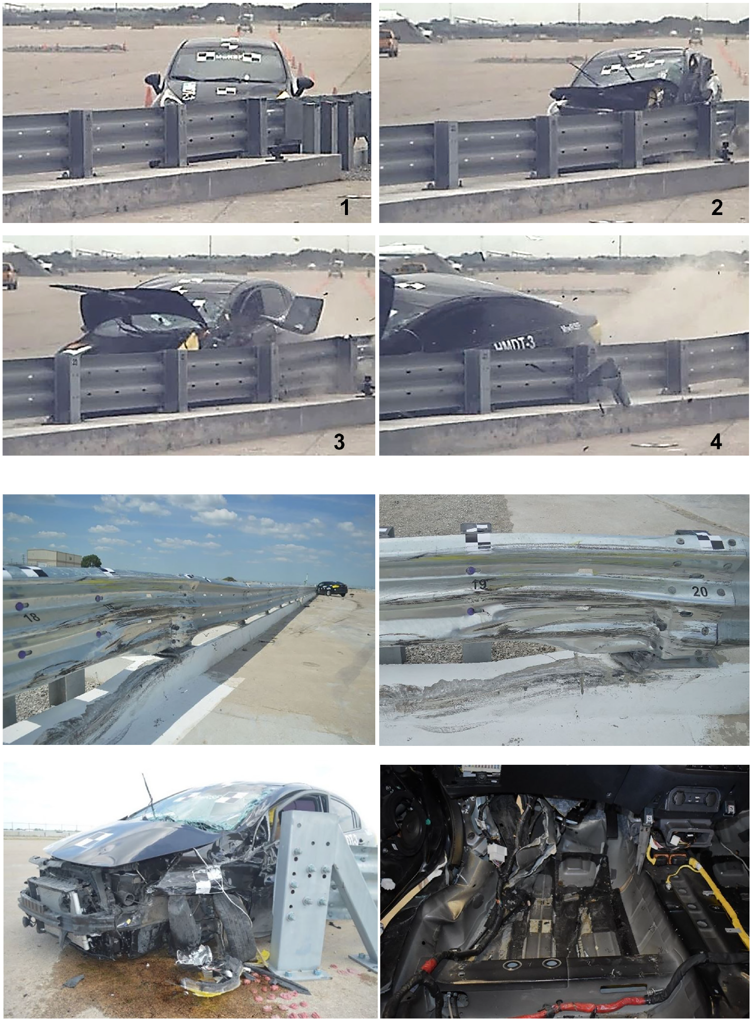
Test HMDT-3: sequential photographs, barrier damage, and vehicle damage.
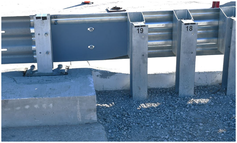
Following the failure observed in test HMDT-3 because of excessive occupant compartment deformation, the HDOT AGT needed to be modified once again. The occupant compartment deformations were the result of localized guardrail deformations adjacent to the first bridge rail post, which formed a sharp pocket and caused wheel snag. To prevent these localized deformations, a reinforcing plate was added to the back side of the nested thrie-beam rail between the first bridge rail post and the last transition post, as shown in Figure 14. The plate measured 43½ in. long × 16 in. tall x ⅜ in. thick and was fabricated from ASTM A36 steel. The lower-upstream corner of the reinforcing plate was tapered to mitigate snag on that corner of the plate. The plate was attached at post locations using the existing 10 in.-long guardrail attachment bolts. Two additional splice bolts were used to connect the reinforcing plate to the nested thrie-beam rail at the mid-span. The reinforcing plate installed within the final AGT configuration is shown in Figure 14.
Modified test installation: test HMDT-4.
Note, the reinforcing plate only prevented localized rail deformations and did not affect overall system strength or stiffness. Thus, the addition of the reinforcing plate would not alter the system performance observed in the previous 2270P crash test (HMDT-2), which satisfied MASH criteria. Therefore, re-conducting MASH test 3-21 on this final design configuration was deemed unnecessary. More details are provided in the Summary and Discussion section.
Test HMDT-4 (MASH Test 3-20)
Test HMDT-4 was conducted according to MASH test 3-20 on the finalized HDOT AGT to the Hawaii Modified Delaware Retrofit Thrie-Beam Bridge Railing mounted on a 9 in-tall elevated sidewalk. The 2,431 lb small car struck the final HDOT AGT configuration at a speed of 60.5 mph and an angle of 25.1° at a location 63.05 in. upstream from post no. 20, the first bridge post. The resulting impact severity was 53.5 kip-ft. The reinforcing plate minimized localized deformations of the guardrail and prevented wheel snag. The vehicle was successfully contained and smoothly redirected with minimal damage to the barrier system and moderate damage to the vehicle, as shown in Figure 15. After striking the barrier system, the vehicle exited the system at a speed of 44.9 mph and an angle of −10.2°. All occupant risk values fell within MASH recommended limits, and the maximum occupant compartment deformations were limited to 2.6 in. in the toe pan region of the vehicle, which did not exceed the MASH limit of 9 in. Therefore, test HMDT-4 satisfied all safety performance criteria of MASH test 3-20.
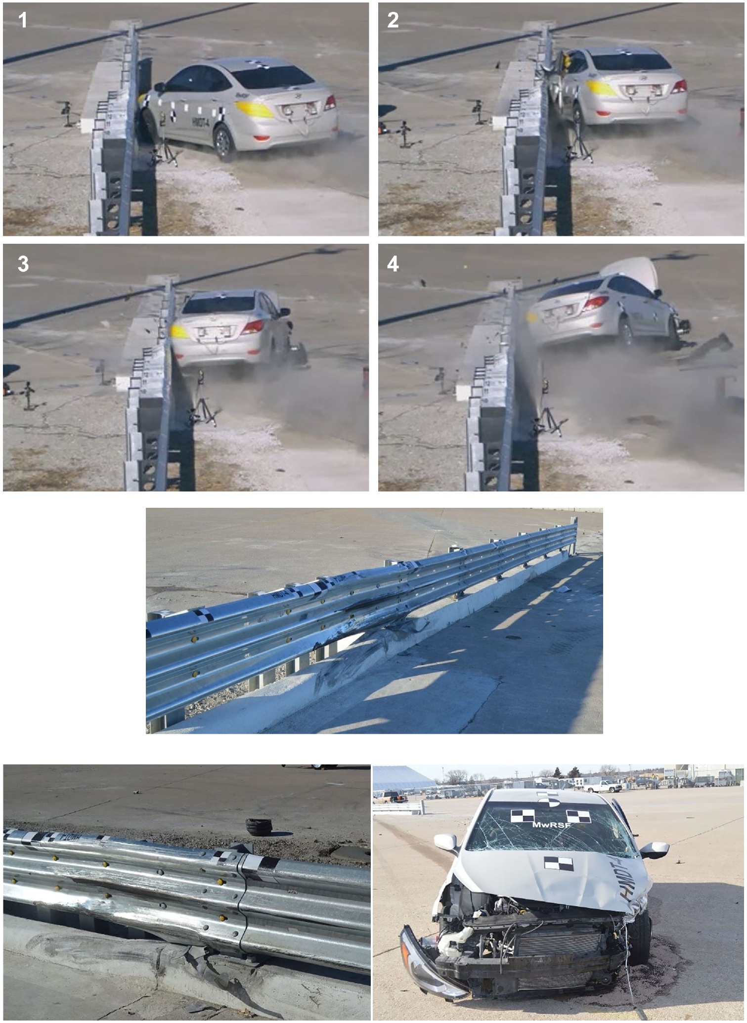
Test HMDT-4: sequential photographs, barrier damage, and vehicle damage.
Summary and Discussion—AGT
Four full-scale crash tests were conducted during the evaluation of HDOT’s AGT to Hawaii Modified Delaware Retrofit Thrie-Beam Bridge Railing. A summary of these MASH TL-3 crash tests is contained in Table 2. After the failure of the preliminary AGT design in test HMDT-1 because of excessive occupant compartment deformation, the AGT was modified to include an additional W6x15 transition post and a flatter vertical taper on the downstream end of the curb adjacent to the elevated sidewalk. This modified AGT design passed MASH test 3-21 (test HMDT-2) but failed MASH test 3-20 (test HMDT-3) because of excessive occupant compartment deformations. Thus, a ⅜ in.-thick reinforcing plate was added behind the nested thrie-beam rail between the first bridge rail post and the adjacent transition post. This final AGT design passed MASH test 3-20 (test HMDT-4).
Crash Testing Summary for HDOT Hawaii Modified Delaware Retrofit Thrie-Beam Bridge Railing
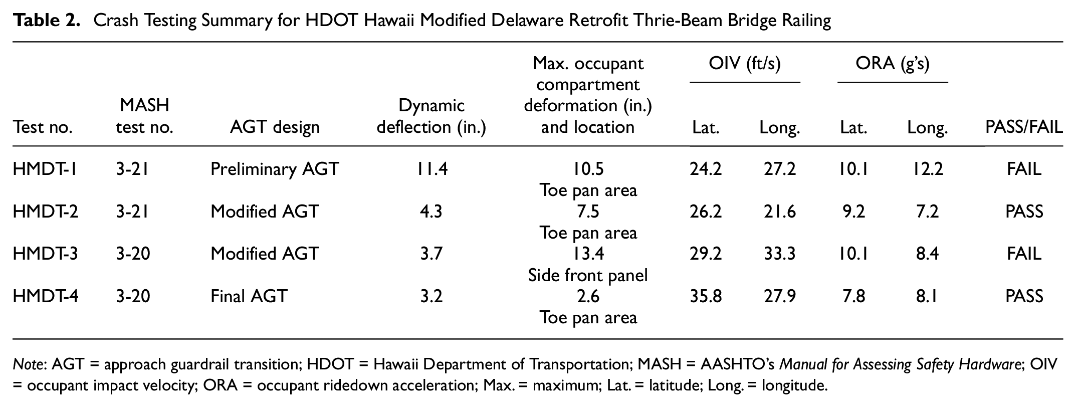
Note: AGT = approach guardrail transition; HDOT = Hawaii Department of Transportation; MASH = AASHTO’s Manual for Assessing Safety Hardware; OIV = occupant impact velocity; ORA = occupant ridedown acceleration; Max. = maximum; Lat. = latitude; Long. = longitude.
The final AGT design was not subjected to crash testing according to MASH test 3-21 conditions. The reinforcing plate that was added to the modified AGT design, which passed MASH test 3-21 (test HMDT-2), only strengthened the guardrail from localized deformations. Because it only spanned between two adjacent posts, the plate did not affect the overall system strength or stiffness. Localized guardrail deformations were not observed during test HMDT-2, so the addition of the reinforcing plate should have no effect on the performance of the final AGT design if subjected to MASH test 3-21 impacts. Thus, re-conducting the 2270P impact on the final AGT design was deemed unnecessary, and the final AGT design was considered crashworthy to MASH TL-3 criteria. Details for the final AGT design are shown in Figure 16.
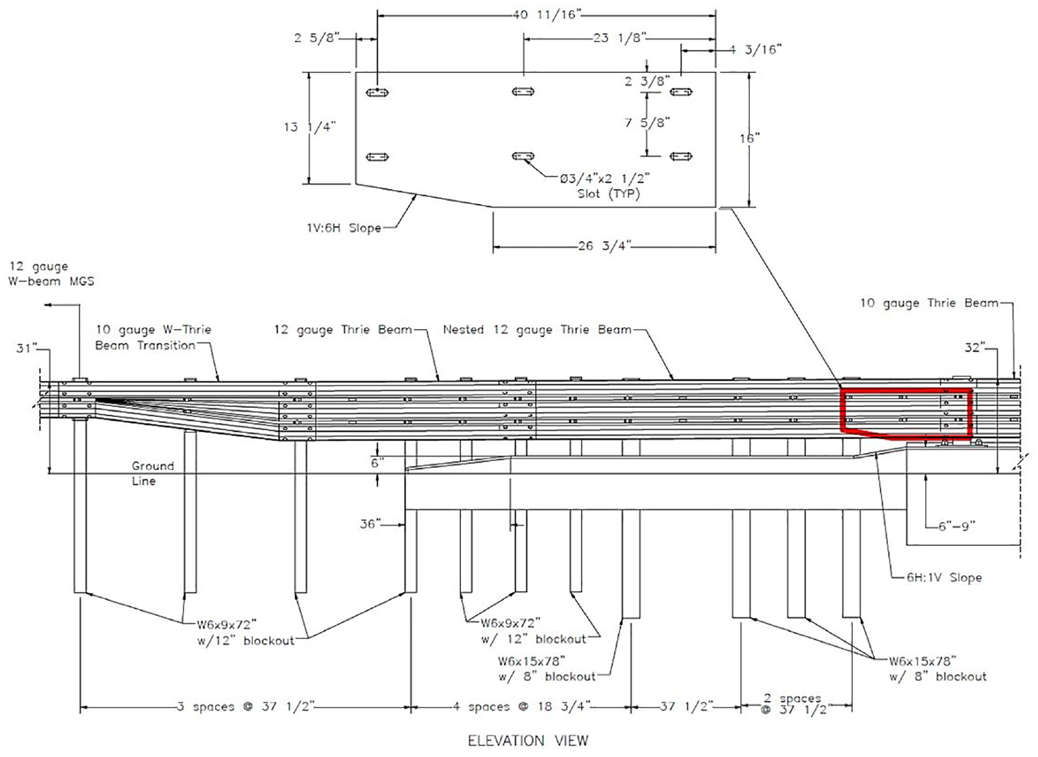
System details for final approach guardrail transition design.
Conclusions and Recommendations
Through three successful crash tests, the Hawaii Modified Delaware Retrofit Thrie-Beam Bridge Railing was shown to be crashworthy to MASH TL-3. Tests were conducted with the bridge railing installed on both 6 in.- and 9 in.-tall elevated sidewalks to bracket the performance of the railing on variable sidewalk configurations. Since the tests on both sidewalk heights satisfied all safety performance criteria, the Hawaii Modified Delaware Retrofit Thrie-Beam Bridge Railing is considered MASH TL-3 crashworthy in combination with elevated sidewalk heights between 6 in. and 9 in. Note, regardless of the sidewalk height, the rail should be installed with a top height of 32 in. relative to the roadway surface.
The HDOT AGT to the Hawaii Modified Delaware Retrofit Thrie-Beam Bridge Railing was also shown to be MASH TL-3 crashworthy through a series of four full-scale crash tests. The final AGT configuration, shown previously in Figure 16, directly connects the MGS on its upstream side to the Hawaii Modified Delaware Retrofit Thrie-Beam Bridge Railing on its downstream side. With the inclusion of this crashworthy AGT, all regions of the guardrail system surrounding these existing bridges have been proven crashworthy. Thus, the complete barrier installation (i.e., the retrofit bridge railing, the AGT, and the adjacent MGS) can be considered MASH TL-3 crashworthy. More details can be found in the reports ( 13 , 14 ).
Testing of the AGT was conducted with the bridge railing mounted on a 9 in.-tall sidewalk to maximize wheel snag potential. The curb below the barrier was tapered vertically at a 6H:1V slope on its downstream end to match the height of the elevated sidewalk. If the bridge rail is mounted on a sidewalk of a lesser height, the 6H:1V slope to match the sidewalk height should be maintained, but the longitudinal length of the vertical taper may be reduced.
Footnotes
Acknowledgements
The authors wish to acknowledge two sources that made a contribution to this project: 1) the Hawaii Department of Transportation for sponsoring and guiding this project and 2) MwRSF personnel for constructing the test articles and conducting the crash tests.
Author Contributions
The authors confirm contribution to the paper as follows: study conception and design: M. Asadollahi Pajouh, K. Lechtenberg, R. Bielenberg, S. Rosenbaugh, R. Faller; data collection: M. Asadollahi Pajouh, K. Lechtenberg, R. Faller; analysis and interpretation of results: M. Asadollahi Pajouh, K. Lechtenberg, R. Bielenberg, S. Rosenbaugh, R. Faller; draft manuscript preparation: M. Asadollahi Pajouh, S. Rosenbaugh, R. Faller. All authors reviewed the results and approved the final version of the manuscript.
Declaration of Conflicting Interests
The author(s) declared no potential conflicts of interest with respect to the research, authorship, and/or publication of this article.
Funding
The author(s) received no financial support for the research, authorship, and/or publication of this article.