
Abstract
Using interlayers made of geosynthetic materials has proved its effectiveness with respect to postponing the appearance of reflective cracking on the surface. In this regard, in a reinforced bituminous interface, the crack first propagates from its origin upward until it reaches the interlayer. When the interlayer has higher stiffness than its surrounding bituminous material, the crack path diverts horizontally along the interlayer plane until the whole energy of the crack dissipates. Nevertheless, this mechanical improvement needs to be further studied to quantify the reinforcement effects of geosynthetic materials in mechanistic-based design of reinforced sections. This study aimed to develop a laboratory test method that not only is able to illuminate the crack resistance effect of geosynthetics but is also able to differentiate the load–displacement curves among different types of reinforced bituminous interfaces. The results led to the advent of a new test device called the crack widening device in which reproducibility and statistical variability of the outcomes were all within the acceptable range. On this ground, using paving fabric showed superior performance among others with respect to energy dissipation capability and retarding the loss in the stiffness modulus during the crack propagation stage compared with the corresponding unreinforced cases. On the other hand, using the reinforcement grids led to a higher initial stiffness of the reinforced structure, especially when embedded between coarse hot mixtures.
Keywords
A traditional pavement maintenance approach to deal with a deteriorated bituminous surface is to mill it up to a specific thickness and refill it with a new hot mix overlay. However, one of the main concerns associated with overlaying is the reflection of existing cracks caused by the movement induced by the traffic loads or moisture and temperature variations in the underlying layers or their combinations thereof. This in turn imposes massive maintenance costs on road authorities to redo their maintenance and rehabilitation measures.
Up until now, no solution has yet been documented in the literature to completely address the prevention of crack development across the overlay. Nevertheless, using interlayers made of geosynthetic materials has proved its effectiveness with respect to postponing the appearance of reflective cracks on the surface by prolonging the crack path and dissipating the energy of the crack during its propagation. In this regard, in a reinforced bituminous interface with geosynthetic materials, the crack first propagates from its origin upward until it reaches the interlayer. When the interlayer has higher stiffness than its surrounding asphaltic material, the crack path diverts horizontally along the interlayer plane until the whole energy of the crack dissipates by stretching the interlayer under the movement. Current laboratory test devices that permit measuring the crack resistance of asphalt overlays are able to apply concurrently shear, tensile, and flexural stresses in the proximity of the crack and provide a stable state of crack propagation: the four-point bending test ( 1 – 3 ), wheel reflective cracking (WRC) test ( 4 , 5 ), wedge splitting test method ( 5 ), direct tensile strength test ( 6 ), modified wheel tracker ( 7 ), Texas overlay tester ( 8 ), and UGR-FACT ( 9 ) are just a few. However, because of demanding large-size specimens, manipulation, and preparation of specimens, the complexity of the analysis of the results and less suitability in incorporating the reinforced structures with geosynthetics, the universal acceptability of these tests methods is limited in practice.
One of the limitations of testing specimens reinforced with geosynthetics is that a large specimen would be required to represent as best as possible the field conditions. The strength of geosynthetic materials is highly dependent on the friction and surface area. One of the objectives of the new test method was to produce and test small-size specimens. The effect of the specimen size on the results is not discussed here.
To meet this objective, four different geosynthetics, three types of geogrids, and one type of geotextile, with different physical and mechanical properties along with reference samples without the interlayer, were embedded in three different dense-graded hot mixes with respect to aggregate size to evaluate the development of the force–crack width curves from the initiation of the crack up to the failure point. This study will also address the following key points:
the repeatability and variability of the proposed laboratory test device;
fracture parameters that enable us to differentiate the mechanical performance of different types of interlayers during crack development;
the best location of the interlayer with respect to the surrounding aggregate size.
As for the organization of the paper, a review of the literature is presented in the first section followed by a description of the materials, specimen preparation procedure, and configuration of the device and test setup. Then, the results and data analysis are discussed. Finally, a summary of the findings along with recommendations will be given.
Research Background
Many scientific proofs encourage using geosynthetic materials as an interlayer between bituminous layers to restrict fatigue cracking and rutting and to delay the appearance of reflective cracking ( 10 ). This rehabilitation solution not only acts as a stress relief and reinforcement layer in the system ( 11 ) but, also compared to a thick overlay, it is much more cost-effective ( 12 ) and sustainable since it allows lower hot mix materials as an overlay, thus decreasing the level of emissions and dissipation of natural sources of materials ( 7 ). However, the degree of effectiveness of the reinforced system depends mostly on the bounding condition provided at the interface ( 13 ). The presence of the interlayer by itself results in a discontinuity between consecutive layers in the pavement system that may lead to a loss in shear strength ( 14 , 15 ). Previous findings showed that a geogrid compared to paving fabric (PF) kept the integrity of the system at the interface level better by giving a higher value of the coefficient of interface bounding (CIB) ( 16 ), which stems from its meshed structure that provides more contact between its adjacent materials. This reduced bounding in the presence of the interlayer, however, plays a barrier role in growing bottom-up cracking, as already proved by the four to five times higher energy dissipated in the crack propagation stage (J-integral) in samples including PF ( 17 ).
Furthermore, the position of the geosynthetic in the pavement system is another important consideration that, with respect to the aggregate size in contact with the interlayer, affects the absorbed energy during the stretching of the geosynthetic under loading ( 18 ). To take advantage of the maximum benefit from the geosynthetic, its location in the pavement structure should be selected according to the type of distress that is supposed to be addressed. With respect to reflective cracking, the minimum amount of crack propagation was observed when the geosynthetic was located at one third of the asphalt overlay thickness from the bottom ( 19 ). In addition, in an attempt to understand the effect of the geosynthetic on the mechanical performance of a multi-layer system under bending, the optimum location of the geosynthetic was proposed at a depth where the tensile stresses resulting from bending are high ( 3 ). In a field study, the placement of the geosynthetic near the interface of an asphalt overlay with an underlying bituminous layer was found to be effective in limiting crack propagation ( 20 ). The results from finite-element modeling of the geosynthetic–asphalt overlay showed that the minimum tensile strain required for the crack propagation over the geosynthetic is obtained when the geosynthetic is placed at one-third depth of the thickness from the bottom surface ( 21 ). However, only a few studies have been performed to evaluate the mechanical performance of geosynthetics during crack propagation when embedded between different sizes of hot mixes.
From the above-mentioned review of the literature, this study will first introduce a novel laboratory approach to differentiate the mechanical behavior of various types of geosynthetics during reflective bottom-up cracking under the displacement mode of loading, and then this behavior will be compared in two different types of interfaces composed of three hot mixes of different maximum aggregate sizes.
Method
To illuminate the evolution of the force–crack width curve in the presence of different types of geosynthetics placed at two different types of bituminous interfaces with respect to aggregate size was the main objective of this study. To reach this target, bi-layer bituminous samples with and without the interlayer were fabricated in the laboratory setting. By assuming that the friction developed between the interlayer and the bottom bituminous layer plays an important role in the crack-resistant performance of the reinforced systems, the geosynthetic was placed at two different interfaces composed of three hot mixtures. Two major criteria were considered for the comparison among the cases: the energy dissipated during crack development up to the failure point (W) and the initial modulus of the system against crack development (E) and its evolution over crack opening, as depicted in Figure 1. These parameters were obtained from an innovative crack development device specifically designed for this study.
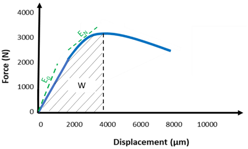
Criteria employed to differentiate among different types of geosynthetics.
Material
In this study, three types of hot mixes normally found in Quebec (Canada) were designed to comply with Transport Quebec’s standard (LC 4202) ( 22 ): (I) a surface course mix with a nominal maximum aggregate size of 10 mm (ESG-10); (II) a binder course mix with a nominal maximum aggregate size of 14 mm (ESG-14); and (III) a base course mix with a nominal maximum aggregate size of 20 mm (GB-20). The mechanical specifications and the gradation curves for each type of mix are presented in Figure 2 and Table 1.
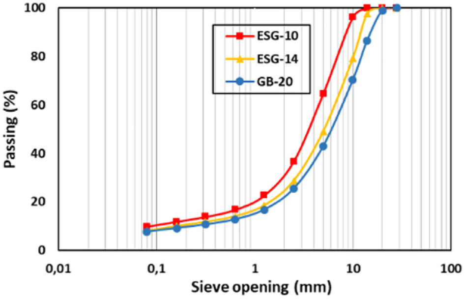
Gradation curves for each type of hot mixture.
Technical Specifications of Hot Mixes
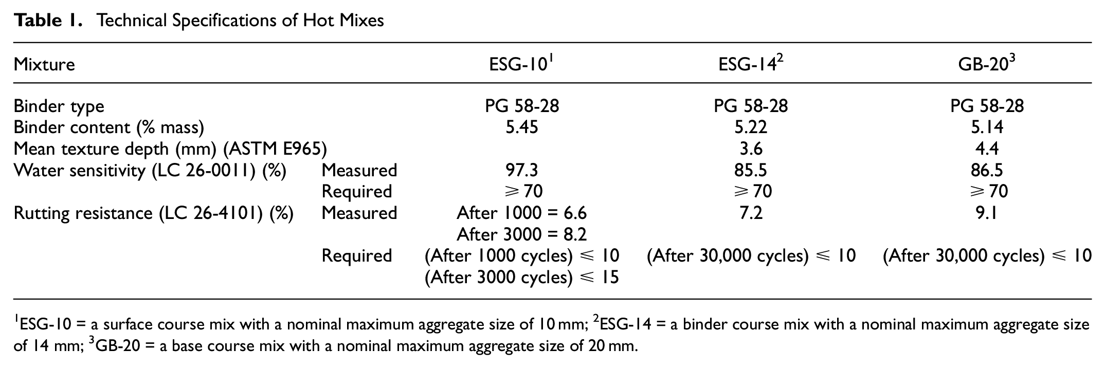
1ESG-10 = a surface course mix with a nominal maximum aggregate size of 10 mm; 2ESG-14 = a binder course mix with a nominal maximum aggregate size of 14 mm; 3GB-20 = a base course mix with a nominal maximum aggregate size of 20 mm.
To reinforce double-layer structures, three types of reinforcement grids and one type of geotextile or PF were employed. The mechanical properties of the geogrids are shown in Table 2. GR and GB refer to the reinforcement grids made of carbon and a mix of glass and carbon fibers respectively, covered with bitumen on both sides, while GV is a type of geocomposite in which one side is covered with bitumen but from the bottom it is covered with a layer of fabric.
Technical Properties of Grids
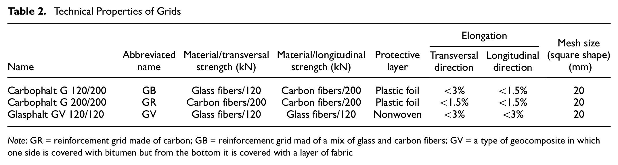
Note: GR = reinforcement grid made of carbon; GB = reinforcement grid mad of a mix of glass and carbon fibers; GV = a type of geocomposite in which one side is covered with bitumen but from the bottom it is covered with a layer of fabric
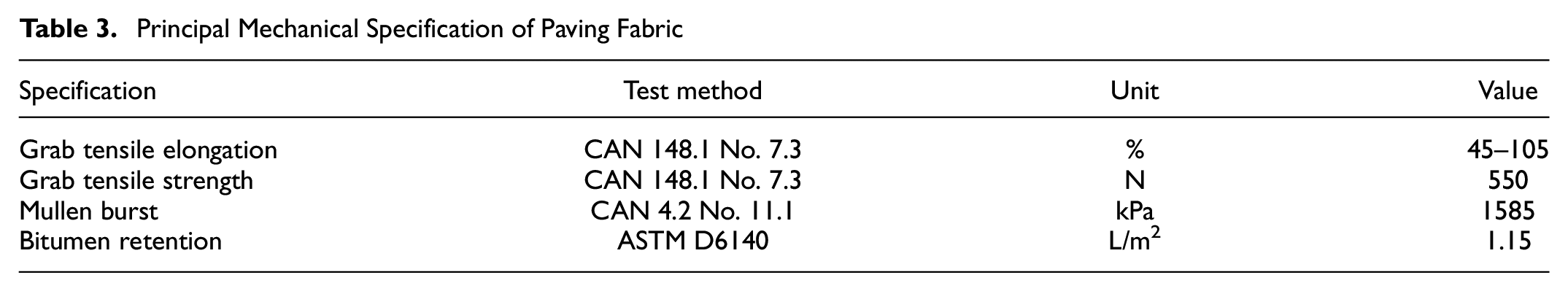
The PF was made of two essential elements: a needle-punched nonwoven fabric saturated with asphalt cement type PG 64-34. The main mechanical properties of the PF, supplied by the manufacturer, are given in Table 3.
Principal Mechanical Specification of Paving Fabric
In general, 10 slabs of size 500 mm × 180 mm × 100 mm, 8 slabs reinforced with geosynthetics, and 2 unreinforced slabs were manufactured. The specimen preparation followed the procedure recommended by the producers of geosynthetic materials utilized in this study. It was started first with the production and compaction of the underlying slab (ESG 14 or GB-20) in the mold of the French roller compactor, according to LC 26-410 (MTQ standard). Thereafter, the slab was left for 48 h for curing at room temperature. Then, three different procedures based on the type of the interlayer were followed as below.
- For unreinforced structures and the reinforced ones with GR and GB reinforcement grids, a slow-setting cationic asphalt emulsion, type SS-1h, was implemented on the top surface of the bottom slab with a syringe and the edge of a spatula. The dosage of the emulsion opted for was 180 g/m2 of residual bitumen, complying with the specifications provided by the manufacturer. Then after 3 h of setting time for the complete breakage of the emulsion in front of a fan, the reinforcement grid was applied on the emulsified surface with the steady-state movement of a gas blow torch to the grid to lightly melt the bitumen that the grid contains. Since the direct exposure of the binders to the flame may result in excessive aging of the material, the following precautions were adopted: not using the full power of the blow torch; keeping a 10 cm distance between the torch and the material; applying a constant-speed movement of the torch on every single strand of the grid, once in one direction and then in the other perpendicular direction.
- For the reinforced structure with the geocomposite, the same procedure as previously described for the reinforcement grid was pursued with two main differences. The dosage was selected as 270 g/m2 and there was no delay between the application of the emulsion on the surface and spreading the geocomposite on the surface without using a blow torch.
- For the structure reinforced with PF, first the asphalt cement was heated up to the compaction temperature and then applied on the surface, as much as 110 g/m2, followed by placing the fabric already cut at the same dimension as the slab on the bottom slab.
After the installation of the interlayer or settling the emulsion in the unreinforced case, the specimen preparation was continued by the compaction of the top bituminous layer (ESG-10 or ESG-14) over the bottom slab at 135ºC. In the final step, cubic shape samples of size 80 mm × 80 mm × 80 mm were cut from each prepared slab and their top and bottom surfaces were perfectly polished with sandpaper to have a full contact between the specimen and the loading plate from the top and the test device from the bottom. It is worth mentioning that a minimum of three openings from the geogrid structure is recommended for better interpretation of the crack resistance behavior of reinforced bituminous layers ( 23 ). The shape, size, and number of specimens used for each structure are shown in Figure 3.
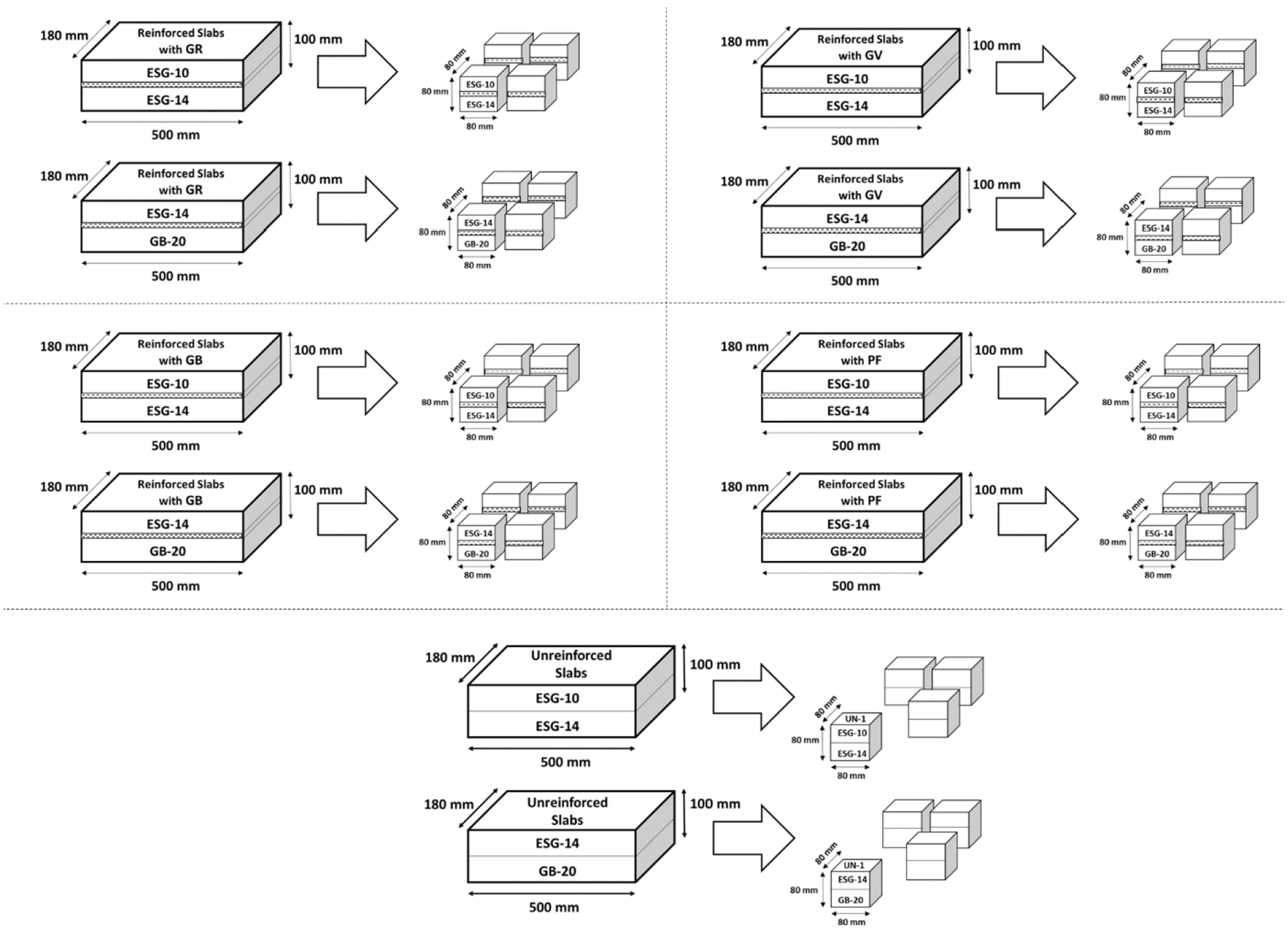
The shape, size, and dimensions of specimens.
Test Setup
Using an interlayer between bituminous layers enhances the crack resistance performance of the whole system ( 23 ). However, the quality of bonding provided at the interface plays a pivotal role in the level of reinforcement. To quantify this effect in mechanistic-based design methods, it is necessary to measure the level of reinforcement when the interlayer changes. To capture this mechanical effect, a crack performance tester device was designed and calibrated in the lab. This device is able to realistically simulate the loss of support from underlying layers while the crack grows from an initial notch up to the top. It was postulated that this methodology could result in having a better vision of the fracture phenomenon in reinforced and unreinforced structures. In the following section, more details are presented on the configuration of the device and test setups.
Crack Widening Device
In search of a test method to measure the crack resistance performance of reinforced bituminous structures that could distinguish among different types of interlayers, a crack resistance performance device was designed that has low complexity, and the time and manipulation required for the specimen preparation is competitive with other devices designed for the same purpose. It also simulates the crack propagation because of loss of support from the bottom layers under environmental and traffic loads. Figure 4 shows the device and the test setup.
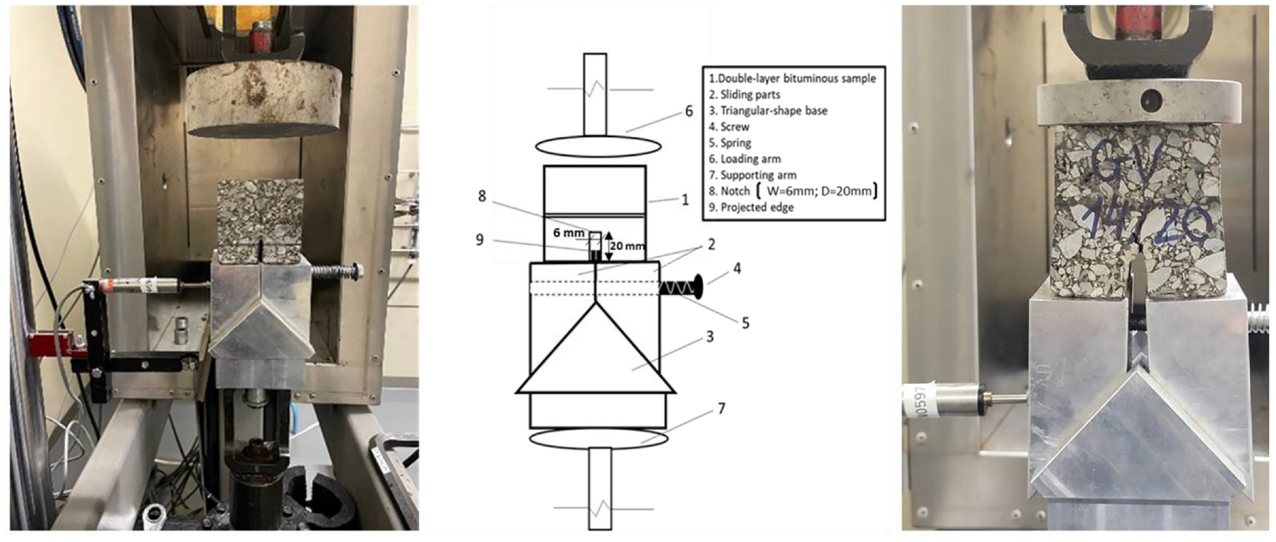
The crack widening device.
The device is made of a triangle shape base that provides support for two sliding parts at the top and the bituminous specimen over it. The role of the screw and the spring in this configuration is to keep the sliding parts in contact with each other before the test starts. However, during the test, there should not be resistance from the spring. The test starts with an initial compressive contact force of as much as 100 N applied at the top surface via an MTS servo-hydraulic loading system and then sliding the movable parts under a constant rate of displacement. The movable parts are located on an inclined surface of 45°, which allows having the same pace of horizontal displacement as the vertical one. As the test starts, the movable parts slide over the inclined surface, and with the help of projected edges inserted in the notch of the specimen, of 6 mm in width and 20 mm in depth, a crack gradually starts to appear at the tip of the notch and propagates vertically upward and after crossing the interlayer reaches the top surface of the specimen, as the movable parts slide over the surface. The horizontal displacement was captured by a Linear Variable Differential Transformers (LVDT) installed horizontally in contact with the side face of the movable part. The main advantage of the device is to have more control over the temperature and rate of loading. In the course of development of the device, different combinations of temperatures and loading rates were tested. However, there as less dispersity of results obtained at room temperature 20 ± 1ºC and a constant loading rate of 2 mm/min. Figure 5 illustrates a typical result obtained from the crack performance tester device on the bituminous structure reinforced with the GR type of reinforcement grid surrounded by the ESG-10 and the ESG-14.
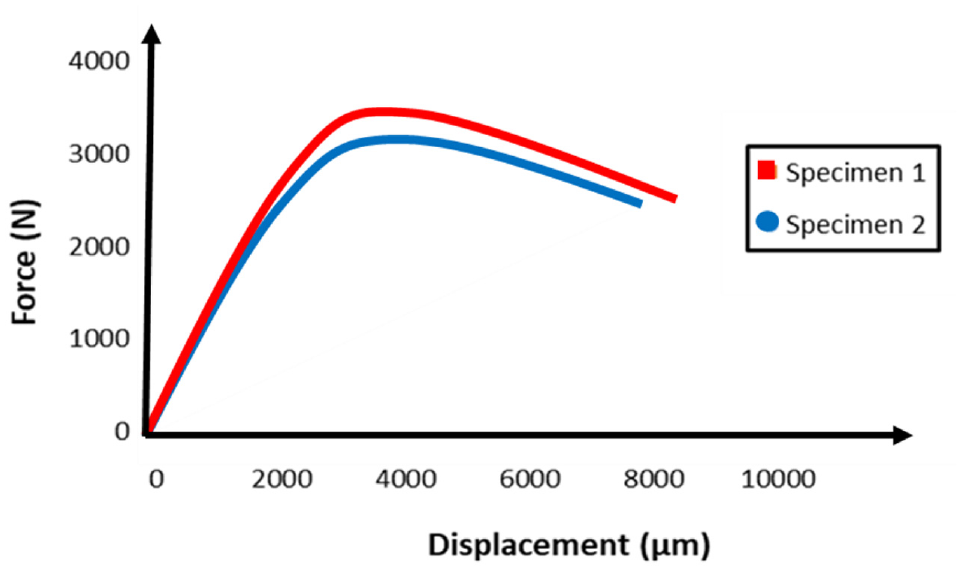
A typical force–displacement curve obtained from the crack performance tester device on two samples including the reinforcement grid made of carbon at the interface surrounded by a surface course mix with a nominal maximum aggregate size of 10 mm and a binder course mix with a nominal maximum aggregate size of 14 mm.
Results and Discussion
In this section, the findings from the testing program are first presented and then analysis and discussion of the results are given. Specifically, the force–crack width curve for bituminous structures with and without reinforcements is evaluated. Afterward, based on the initial stiffness and energy dissipated by the interface during the crack development stage, the major mechanical differences among differently treated interlayers are identified.
Result and Discussion for Energy Dissipation
Figure 6 provides a comparison of the energy dissipated during the bottom-up crack propagation stage among different types of interlayers in two different structures, that is, ESG-10 over ESG-14 and ESG-14 over GB-20. These results are obtained from the area limited to the force–displacement curve up to the failure point (e.g., Figure 5) and averaged from two replicates for each type of interface. As can be seen, from the type of structure perspective, the interfaces reinforced with different types of reinforcement grids and PFs show improved performance when accommodated in coarse-graded mixtures. This result is in line with previous researches in which using a layer of geosynthetic interlayer resulted in an outstanding performance against reflective cracking ( 5 , 24 – 26 ). On the other hand, for the unreinforced structure, the energy required for the crack to propagate from the tip of the notch to the surface is noticeable when surrounded by fine-graded mixtures.
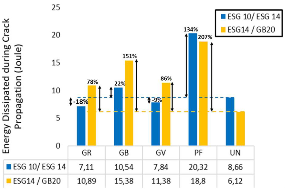
Changes in energy dissipation during the bottom-up crack propagation stage in two different double-layer structures.
As far as the type of interlayer is concerned, the interface with the PF showed superior performance in delaying crack propagation compared with that reinforced with grids. However, in the case of the reinforcement grids, the interface reinforced with the GB grid experienced the best performance both in fine- and coarse-graded mixtures, while the GR and the GV grids only presented an improved performance in coarse mixtures and they had a comparable performance in both types of structures. The percentage of improvement in energy dissipation capability by different types of bituminous interfaces compared with corresponding unreinforced cases is shown in Figure 6.
Result and Discussion for Crack Stiffness Evolution
To understand how the system including different types of interlayers reacts to the crack development, the changes in the stiffness modulus from the initiation of the test up until the failure point was studied by taking the slope of the tangent on the force–displacement curve into account. Figures 7 and 8 demonstrate the evolution of the stiffness modulus over the crack opening for different types of interfaces in two different structures.
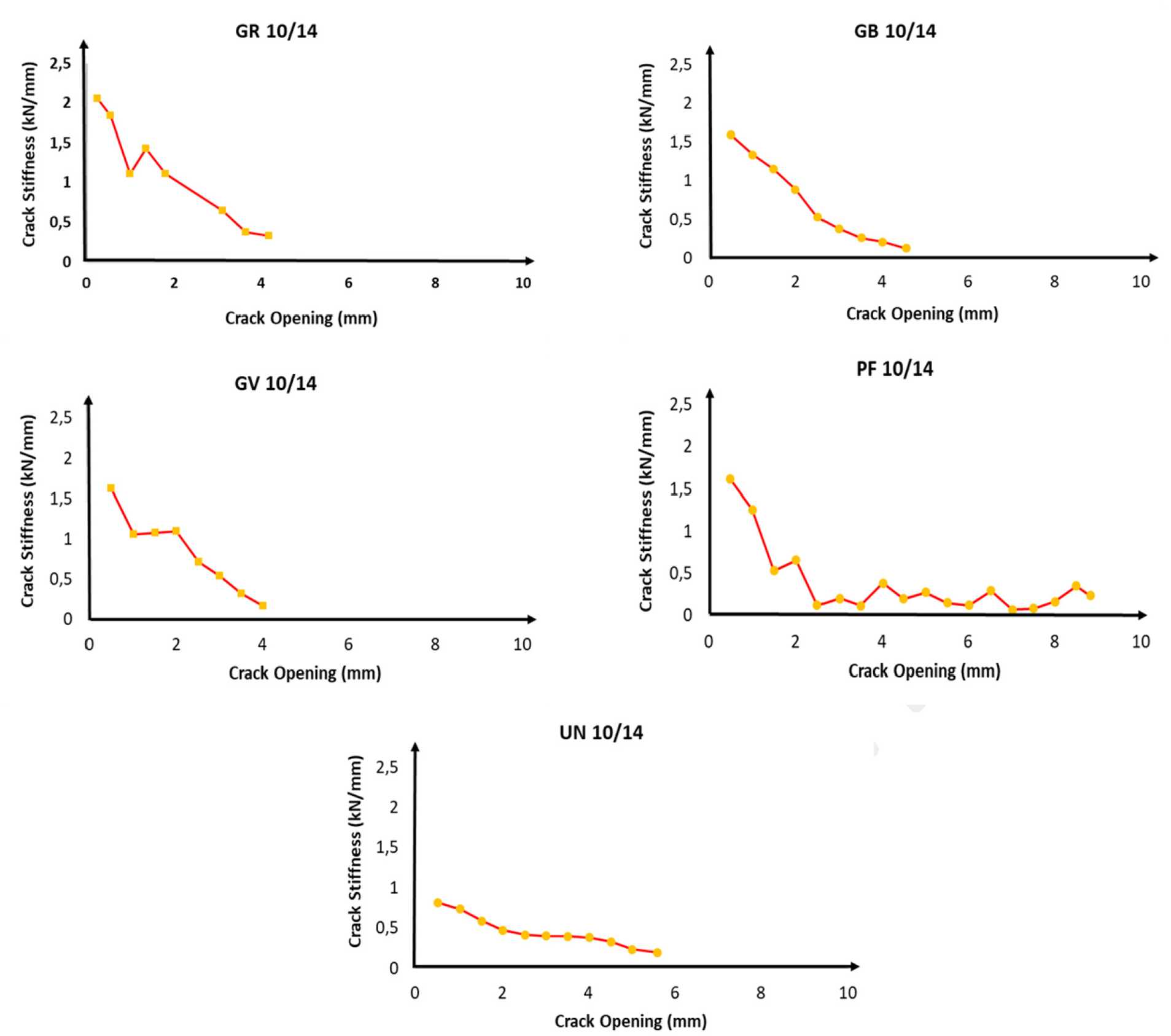
Crack stiffness evolution in double-layer structures composed of a surface course mix with a nominal maximum aggregate size of 10 mm over a binder course mix with a nominal maximum aggregate size of 14 mm reinforced with different types of interlayers and the unreinforced structure.
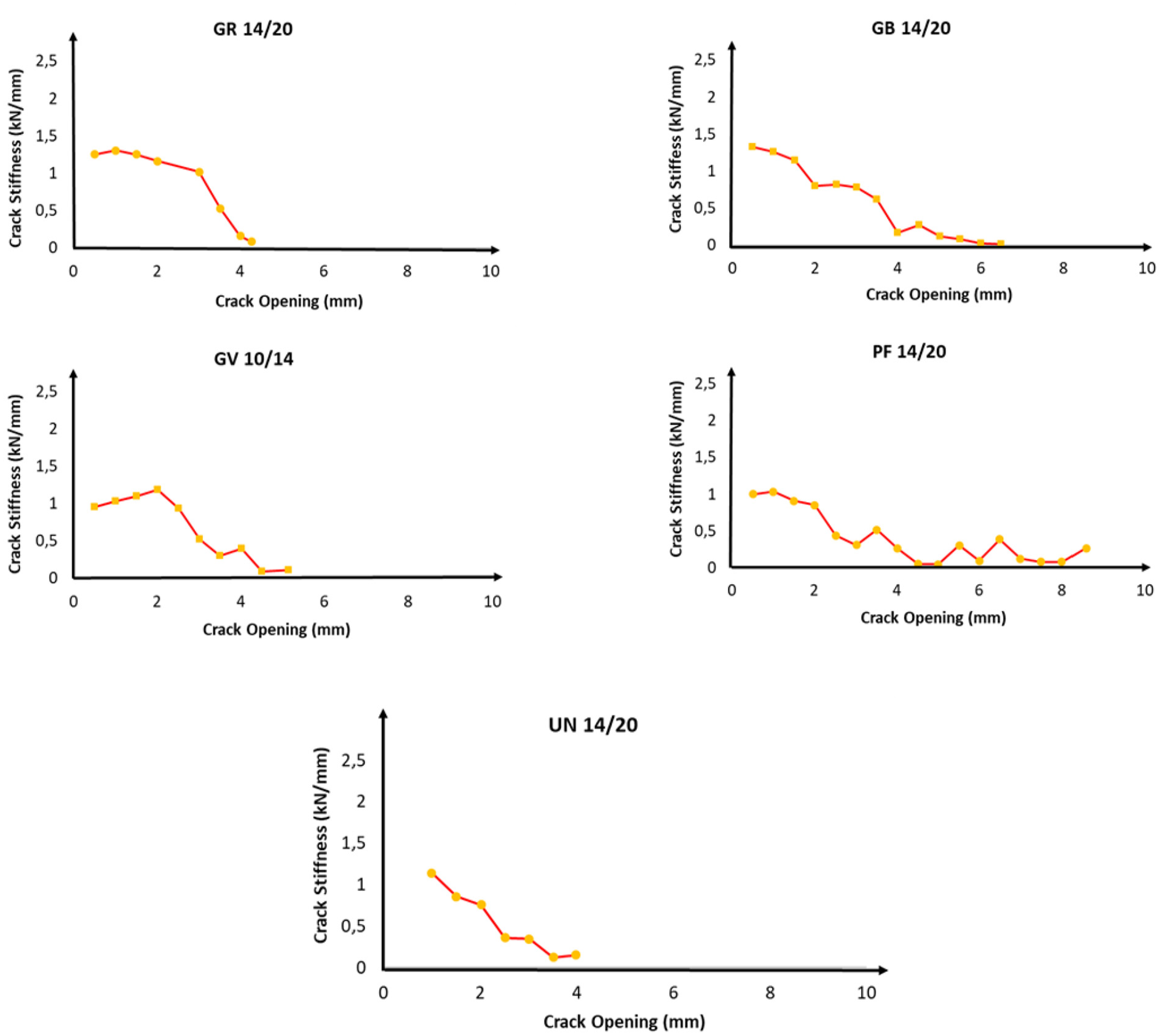
Crack stiffness evolution in double-layer structures composed of a binder course mix with a nominal maximum aggregate size of 14 mm over a base course mix with a nominal maximum aggregate size of 20 mm reinforced with different types of interlayers and the unreinforced structure.
In the structure composed of ESG-10 and ESG-14, a higher initial modulus was observed in the structure with the GR reinforcement grid. However, the GB reinforcement grid was able to undergo higher displacement compared with the two other reinforcement grids. Moreover, the GB reinforcement grid kept the structural integrity of the system almost unchanged, while in the GR and the GV reinforcement grids, a hardening effect was followed by a slight drop in the stiffness modulus of the system when the crack width reached 1.5–2 mm. On the other hand, in the case of the system reinforced with the PF, a sharp reduction in the stiffness of the system with respect to lower crack width was experienced. Nevertheless, the system was able to keep its structural integrity at a very large crack width because of the elasticity from the combined effect of the asphalt cement and the fabric. In addition, in an unreinforced structure, although the system showed a higher crack width before failure, the stiffness modulus of the system was the lowest.
In the structure fabricated with ESG-14 and the GB-20, as shown in Figure 8, a similar trend was traced with the following differences. In the structures with the GR and GV reinforcement grids, the hardening effect was replaced by a significant improvement in the stiffness modulus of the system in the crack width between 1.5 and 2 mm. This could be referred to as the activation of the reinforcement effect, which in the presence of the coarse aggregates occurred in these two types of reinforcement grids. However, in the GB grid, the stiffness modulus was smoothly reduced from a higher initial modulus to a higher crack width. On the other hand, for the system with PF, a similar pattern as the fine-graded structure was observed. Nevertheless, the improvement in the initial stiffness modulus of the system was tangibly lower in the coarse-graded structure. Furthermore, the unreinforced structure, unlike the corresponding fine structure, showed a higher initial modulus. However, the crack width at the failure point was 30% reduced.
Figure 9 presents a view of changes in percentage in the mechanical performance of the bituminous interface with respect to the maximum force, maximum displacement, and initial crack stiffness when reinforced with different types of geosynthetics, compared with corresponding unreinforced cases. With respect to the maximum force, in the ESG-10/ESG-14 structure, the interface including a layer of PF had the highest resistance against shear stresses transferred from the crack during its propagation, followed by the GB, GR, and GV grids, respectively. Nonetheless, in the case of ESG-14/GB-20, it was the GB grid that showed the highest resistance, while the PF had the lowest rank.
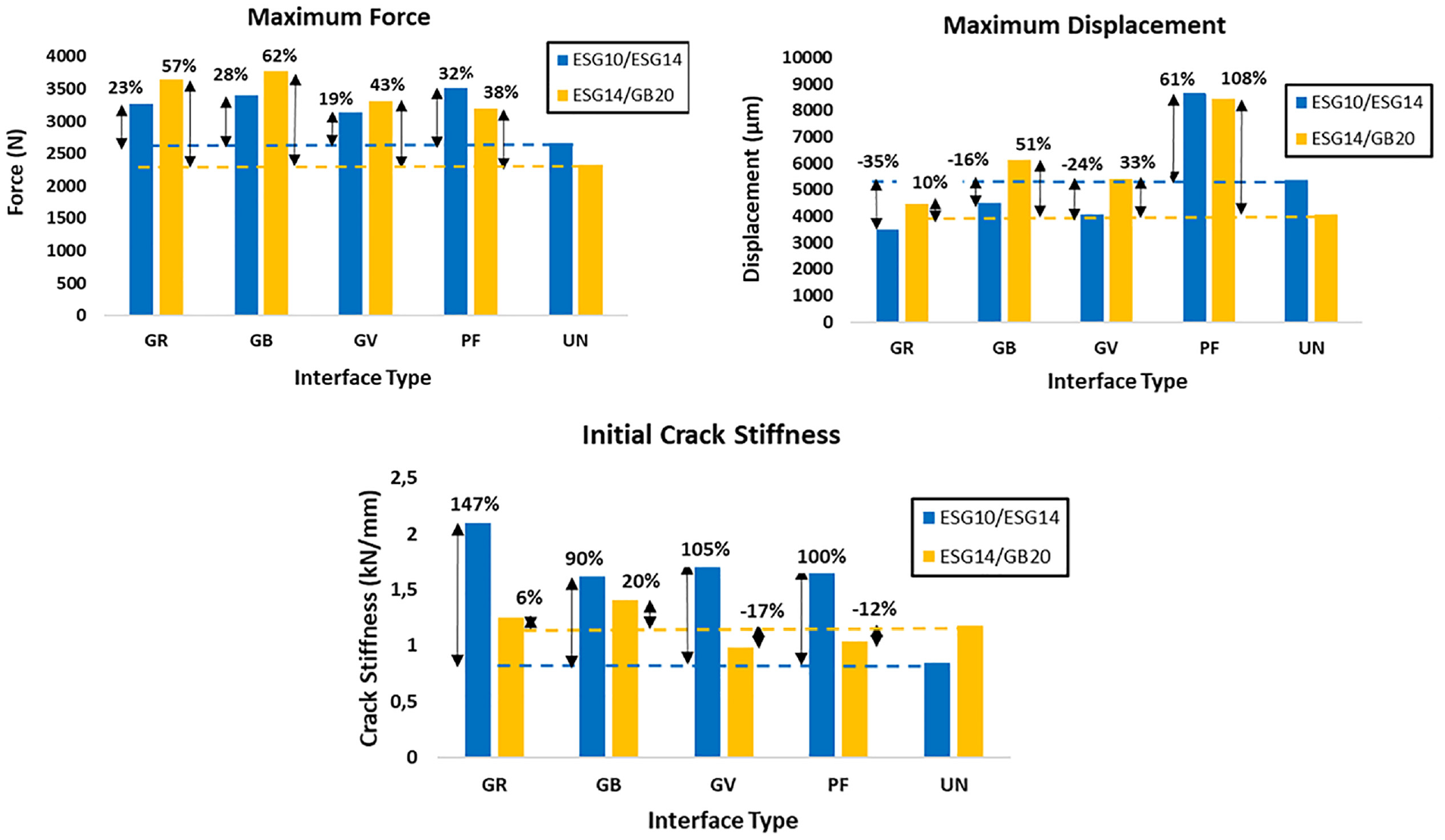
Changes in maximum force and displacement and initial crack stiffness in different interface types.
Concerning maximum displacement at maximum force, in both types of structures, using a layer of PF at the interface led to a significant improvement in the structural integrity of the system, even in large crack openings. However, all types of reinforcement grids at the interface surrounded by ESG-10 and ESG-14 presented inferior performance compared with the unreinforced interface in a similar structure.
As for the initial crack stiffness, all types of geosynthetics induced a 2–2.5 times higher initial modulus at the interface of fine-graded mixtures compared with the unreinforced case. However, this improvement was not of great importance at the interface of coarse-graded mixtures, while in the case of the GV grid and PF, the crack stiffness on average dropped as much as 15%.
Conclusions
In this study, an innovative laboratory approach was developed to investigate the crack resistance performance of double-layer bituminous structures reinforced with different types of interlayers. To have a better insight into the effect of the aggregate size used in the hot mixture on the mechanical performance of the interlayer, three different types of hot mixtures were utilized with respect to the nominal maximum aggregate size: ESG-10, ESG-14, and GB-20. Two mechanical indices were considered for understanding the differences in mechanical performance compared with the corresponding unreinforced cases: energy dissipated during the bottom-up crack propagation stage and the evolution of the stiffness modulus during the crack opening. Based on the findings from this laboratory study, the following conclusions were acquired.
- With respect to the energy required for the crack to propagate from the bottom to the top surface, the PF showed superior performance to the unreinforced one regardless of the type of the mixture it is in contact with. However, only using the GB reinforcement grid at the bituminous interface resulted in an almost two times enhanced performance compared to the corresponding unreinforced case. In the case of GR and GV reinforcement grids, the energy dissipation performance was doubled for fine-graded mixtures.
- Using the PF at the interface led to a very slow reduction in the rate of loss in the stiffness modulus of the combined system compared to the other types of interlayers.
- In all the reinforced structures, the initial modulus was remarkably higher than the corresponding unreinforced cases. This benefit was of great importance when using the carbon-made reinforcement grid (i.e., GR) at the interface. However, in the case of the geocomposite made of a layer of glass fiber grid, the improvement in the initial modulus was not tangible.
- In comparison with unreinforced structures, using reinforcement grid types GR and GB led to a higher initial modulus and smoother loss of the stiffness modulus. In the case of using a geocomposite (i.e., GV) this improvement was only associated with higher displacement when applied between coarse-graded mixtures. On the other hand, the PFs showed the lowest reduction in the loss of stiffness modulus because of yielding and significant horizontal displacement before failure under the imposed shear stresses.
- For gaining the most benefits from the reinforcement effect of the interlayers, the reinforcement grids showed improved performance while embedded between coarse-graded mixtures, namely, between a binder layer and a bituminous base layer. Nevertheless, in the case of using PF, the higher initial modulus was recorded while using it between a surface layer and a binder layer.
It is worth mentioning that, along with the current results, more experimental works are required to check the validity of the results with a larger matrix of mixes and different gradations, binder contents, geosynthetic materials, and temperatures. In addition, the evolution of the stiffness modulus of the reinforced systems can be modeled in finite-element-based modeling software to predict the appearance of reflective cracking more precisely in mechanistic-empirical pavement design methods. Furthermore, the test can be redone on one type of interlayer placed at different depths in the bituminous structure thickness to evaluate the claim that the best location for the reinforcement interlayer is one-third from the bottom of the lift.
Footnotes
Acknowledgements
The authors would like to thank the TEXEL Corporation, the S&P reinforcement company, and the Natural Sciences and Engineering Research Council of Canada (NSERC) for their financial support and geosynthetic provision.
Author Contributions
The authors confirm contribution to the paper as follows: study conception and design: E. Solatiyan, A. Carter; data collection: E. Solatiyan, V.T. Ho; analysis and interpretation of results: E. Solatiyan, V.T. Ho, A. Carter; draft manuscript preparation: E. Solatiyan. V.T. Ho, A. Carter, M. Vaillancourt, N. Bueche. All authors reviewed the results and approved the final version of the manuscript.
Declaration of Conflicting Interests
The author(s) declared no potential conflicts of interest with respect to the research, authorship, and/or publication of this article.
Funding
The author(s) disclosed receipt of the following financial support for the research, authorship, and/or publication of this article: This work was supported by the Natural Sciences and Engineering Research Council (NSERC) and TEXEL Corporation. The authors gratefully acknowledge their financial support.