
Abstract
In automated lane-free traffic, vehicles can choose any arbitrary lateral location. This enables vehicle flocking where, compared to platooning, the grouping of vehicles is possible with smaller space gaps, not only longitudinally but also laterally. Vehicle flocking can fulfill several purposes, such as increasing the road capacity, saving energy by reducing the aerodynamic drag force, and dampening shockwaves. Within this paper, we develop a control framework for modeling vehicle flocks in automated lane-free traffic. The proposed control algorithm considers two types of agents:
Keywords
The transportation sector in the 21st century faces enormous challenges. The rise in vehicle miles traveled on limited, costly transportation infrastructure leads to massive traffic congestion, causing environmental and economic damages and reduced traffic safety. The emergence and advancement of connected and automated vehicles (CAVs) equipped with highly precise sensors and smart technologies for fast and reliable vehicle-to-vehicle (V2V) and vehicle-to-infrastructure (V2I) communication offers the possibility to develop new road management strategies. CAVs are able to make fast decisions based on control strategies to avoid collisions, efficiently move forward, and also cooperate with other vehicles. In freeway traffic, for example, CAV platoons can be formed that drive with a very short headway, resulting in fuel saving and increased highway capacity ( 1 ). While the platoon speeds of human-driven vehicles will depend on the speed of the front vehicle, CAV platoons can agree on a common desired speed or follow external recommendations ( 2 ). If receiving further information, platoons can optimally plan their trajectories, for example, to smoothly decelerate when downstream congestion is detected ( 3 ) or to minimize fuel consumption based on a given road inclination ( 2 ). However, the benefits only apply to the vehicles in one specific lane and long platoons can hinder other vehicles from performing lane changes or even entering or leaving the freeway ( 4 ). Considering that CAVs cannot only cooperate with vehicles in front or behind them but also with all surrounding vehicles, lane changes can be performed cooperatively and, eventually, the sheer need for fixed vehicle lanes can be questioned in the case of a fully connected and automated environment. Vehicle lanes were introduced as essential instruments for simplifying driving tasks for human drivers and increasing traffic safety when automobiles prevailed as an important means of transport with higher speeds in the 20th century. However, as stated by Papageorgiou et al. ( 5 ), this happened at the expense of road capacity, as lanes reduce the lateral static occupancy on motorways by almost 50%. Additional dynamic capacity loss is caused by lane-changing maneuvers. Papageorgiou et al. ( 5 ) introduced a novel paradigm for freeway traffic in which vehicles are not limited to traffic lanes but rather can use the entire road width, allowing for an increase in the efficiency of traffic operations. Recent evaluations demonstrate a great potential for increasing road capacity in a fully automated lane-free environment ( 6 ). The positive impacts could further be increased by traffic management strategies that support the formation of groups of vehicles with certain headways and speeds.
Since lanes no longer exist in the assumed lane-free traffic environment, flocking will be developed as a generalization of platooning. Flocking is considered a novel approach for grouping vehicles not only longitudinally, but also laterally (Figure 1a shows an example). It is inspired by flocking phenomena observed in nature (e.g., from birds and fish) and can fulfill several purposes, such as increasing the road capacity, saving energy by reducing the drag force, sharing resources (e.g., electric charging, internet), and playing the role of a traffic control measure. This paper builds on previous publications by Berahman et al. ( 6 ) and Rostami-Shahrbabaki et al. ( 7 ) and extends the existing concepts by introducing a new flock management layer that allows for achieving certain vehicle headways, flock speeds, and lateral distributions of vehicles on the road. Potential use cases of such a flock management are shown in Figure 1b. They include variable speed limits in oversaturated traffic conditions, optimally navigating vehicles through curves or construction zones, or making a flock move to the side to let an emergency vehicle pass.
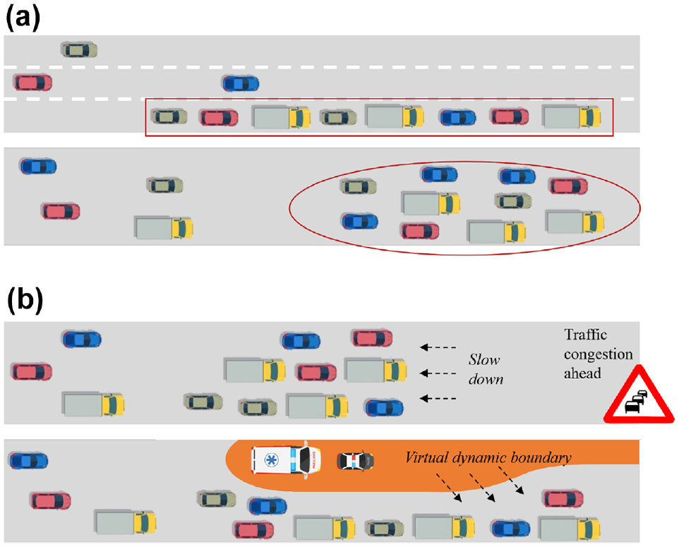
Examples of vehicular flocking: (a) schematic representation of a vehicle platoon and a vehicle flock and (b) flock management use cases.
The outline of the paper is as follows: the next section provides the background and most relevant literature with respect to vehicular flocks. Following that, the applied methodology is explained in detail. The simulation setup that is used for the implementation and evaluation of the presented concept is described afterward. The section following that discusses the results and shows the key features of the algorithm. Finally, a conclusion and outlook are given in the conclusion section.
Background and Literature Review
CAV Platoons
CAV platoons take advantage of fast and reliable V2V communication and automated maneuvering to significantly reduce vehicle headways. Several papers present algorithms for platoon formation and analyze their effects on individual fuel consumption as well as overall environmental, traffic safety, and capacity benefits ( 8 – 11 ). Smaller vehicle gaps are beneficial with respect to the aerodynamic drag force and can therefore significantly reduce fuel or energy consumption ( 9 , 10 ). In addition, freeway capacity is increased if vehicles are able to drive at shorter distances ( 8 ). One important requirement for platooning algorithms is string stability, that is, ensuring that small disturbances with the front vehicle’s trajectory are not amplified along the vehicle string ( 12 , 13 ). Platoon forming can be challenging if vehicles in the platoon have different destinations ( 14 ).
CAV Platoons Across Multiple Lanes
Motivated by the goal of further increasing road capacity, a few researchers have developed concepts for lane-based platooning across multiple lanes. Kato et al. ( 15 ) conducted a simulation study on cooperative driving formations across multiple lanes with vehicles starting from an initial state. Their model could handle different events, such as splitting, merging, overtaking, and obstacle avoidance. Several researchers ( 16 – 20 ) used ideas from swarm robotics for developing multiple-lane platooning strategies that control each vehicle in the group longitudinally and laterally. Hao et al. ( 21 ) developed a model that manages platoons in two dimensions at signalized intersections. Xu et al. ( 22 ) proposed a method for multi-lane vehicle formation control that is combined with a method to calculate conflict-free passing sequences at unsignalized intersections.
Lane-Free CAV Traffic
According to Papageorgiou et al. (
5
), the lateral occupancy in current lane-based traffic on motorways is only slightly higher than
In Sekeran et al. ( 23 ), an overview of the history of lane-free traffic is provided. Malekzadeh et al. ( 24 , 25 ) extended the TrafficFluid concept by mathematical models for real-time internal boundary control by which the total road width is shared among the two directions in dependence of the bi-directional demand. Thereby, the total flow efficiency of both directions can be maximized. Control strategies and path planning algorithms for CAVs in the lane-free environment were designed by Levy and Haddad ( 26 ), Karafyllis et al. ( 27 ), Yanumula et al. ( 28 ), and Troullinos et al. ( 29 ). These strategies avoid collisions with other vehicles, obstacles, and the road boundary and optimize vehicle speeds. Some of them also cover additional objectives, such as minimizing fuel consumption or maximizing passenger comfort. Most approaches are based on longitudinal and lateral artificial forces/potential fields that determine the two-dimensional vehicle acceleration. Troullinos et al. ( 30 ) developed a simulator (TrafficFluid-Sim) for CAVs in lane-free traffic built on the open-source traffic simulation software SUMO. Using this simulator, in Rostami-Shahrbabaki et al. ( 31 ), a so-called potential line approach is developed by which each vehicle receives a specific desired lateral location based on its desired speed. This approach mimics the behavior of today’s traffic where faster vehicles drive on the right-hand side of the road, which leads to much higher throughput because of the harmonized traffic movements. Berahman et al. ( 6 ) proposed a driving strategy for CAVs in the lane-free traffic environment combining artificial forces and a reinforcement learning approach. An artificial ellipsoid border is assumed around each vehicle with lateral and longitudinal forces to reach closer space gaps, supplemented by an additional longitudinal repulsive force for avoiding longitudinal collisions. The methodology was implemented in the SUMO traffic simulator and promising results were shown: the maximum traffic flow in the lane-free scenarios was about two times higher than in lane-based traffic and the speed deviation from the vehicles’ desired speeds at maximum flow was around half that of the lane-based model. This shows the great potential of lane-free traffic for increasing road capacity.
The Concept of Flocking
According to Caruntu et al. ( 19 ), flocking is a simple approach in which entities form large groups without colliding, based on local interactions, to move toward a common target. The flocking phenomenon can be observed in nature, where some natural species, such as birds, fish, or ants, travel as a flock, school, or herd for various reasons: to protect themselves from the threat of predators; to search for food; for energy efficiency; or for social and mating activities. There is no central control unit. The complex but coordinated flock formation and motion are merely the aggregate result of the actions of individuals based on their local perception. In comparison to structured approaches where individuals follow a leader with a fixed path, this is a self-organized behavioral approach with decentralized control in which each individual has a desired behavior. According to Reynolds ( 32 ), flock behavior is produced by three basic, simple rules of interaction:
flock centering: individuals should stay close to other individuals in the flock;
collision avoidance: collisions with other flock members have to be avoided;
velocity matching: individuals should travel at a common speed.
Flocking was analyzed by numerous studies for animals ( 33 , 34 ) and chemical entities ( 35 ), and adapted to mobile robots ( 36 , 37 ), autonomous drones ( 38 ), satellites ( 39 ), general multi-agent systems ( 40 , 41 ) and more. There are several reasons for the application of flocking within these use cases: using space more efficiently, reducing space gaps for resource sharing, or saving energy in operations.
Most control strategies for flock formations are based on artificial forces, consensus control, and graph theory. The Reynolds rules can be modeled by potential fields based on artificial forces. Attractive forces make individuals join formations, while repulsive forces make them avoid collisions with obstacles and flock mates. The individuals move along the gradient direction of the potential fields. Within consensus control approaches, individuals use the aggregate information from neighbors to reach a common goal, for example, the weighted average of speeds. Within graph theoretical approaches, vertices represent individuals and edges indicate the communication between these. Based on these approaches, specific formations among vehicles can be reached.
CAV Flocking in Lane-Free Traffic
The general road capacity increase within lane-free traffic could be further amplified by the application of CAV flocking. Compared to platoons in lane-based traffic, CAV flocks have more degrees of freedom for choosing positions and thus can reach significantly smaller lateral and longitudinal space gaps. Besides that, CAV flocks could fulfill additional purposes: saving energy by building aerodynamically efficient formations and reducing the drag force, sharing resources (e.g., electric charging, internet) among CAVs in a flock or playing the role of a traffic control measure (e.g., dampening speeds). However, until now few studies have dealt with vehicular flocking in non-lane-discipline or lane-free traffic. Tang and Li ( 42 ) developed stable longitudinal and lateral consensus-based control protocols for flocking of non-lane-discipline CAVs. Chuang et al. ( 43 ) developed cooperative control algorithms for CAV flocking using pairwise attractive–repulsive interactions. The authors found that critical thresholds exist between coherent, stable, and scalable flocking and the dispersed or collapsing motion of the group. Rostami-Shahrbabaki et al. ( 7 ) developed a decentralized two-layer approach for vehicular flocking in lane-free traffic. In the tactical layer, the control mode is defined and vehicles are matched. In the operational layer, the inter-vehicle forces and vehicle movements are calculated based on defined motion dynamics. Self-organized, collision-free vehicular flocks result from the defined flock attraction and repulsion forces.
Compared to the authors’ previous work ( 7 ), which considered different zones and control modes for the movement of vehicles, in this work, vehicular flocking is developed using a single energy function and the principles of graph theory. The general framework is built on the flocking algorithm developed by Olfati-Saber ( 41 ). A dynamic graph is constructed based on the elliptic distance between the vehicles in the flock. This graph is used in the consensus approach for velocity matching of the flock members. The developed energy function provides the necessary inter-vehicle force for flock repulsion and attraction. Based on this function, the vehicles are automatically located in the flock, where the total energy is minimized, unless there are some constraints, such as boundary conditions, that result in vehicle locations where the energy level is higher. In addition, the control algorithm considers the behavior of a virtual leader as the navigational feedback for the adaption of the flock to a desired path and speed. The developed methodology is explained in detail in the following section.
Methodology
Each vehicle is modeled using discrete double integrator dynamics and moves on the road with implied longitudinal and lateral accelerations. The discrete-time setup is best suited to the computer implementation of the approach. The control algorithm has three terms: (1) flocking force, (2) consensus term, and (3) navigational feedback derived from the virtual leader. The overall methodology is visualized in Figure 2. The top part of the figure shows that the flocking force (part 1) is realized via an energy function that applies to each individual vehicle in the flock (denoted as the
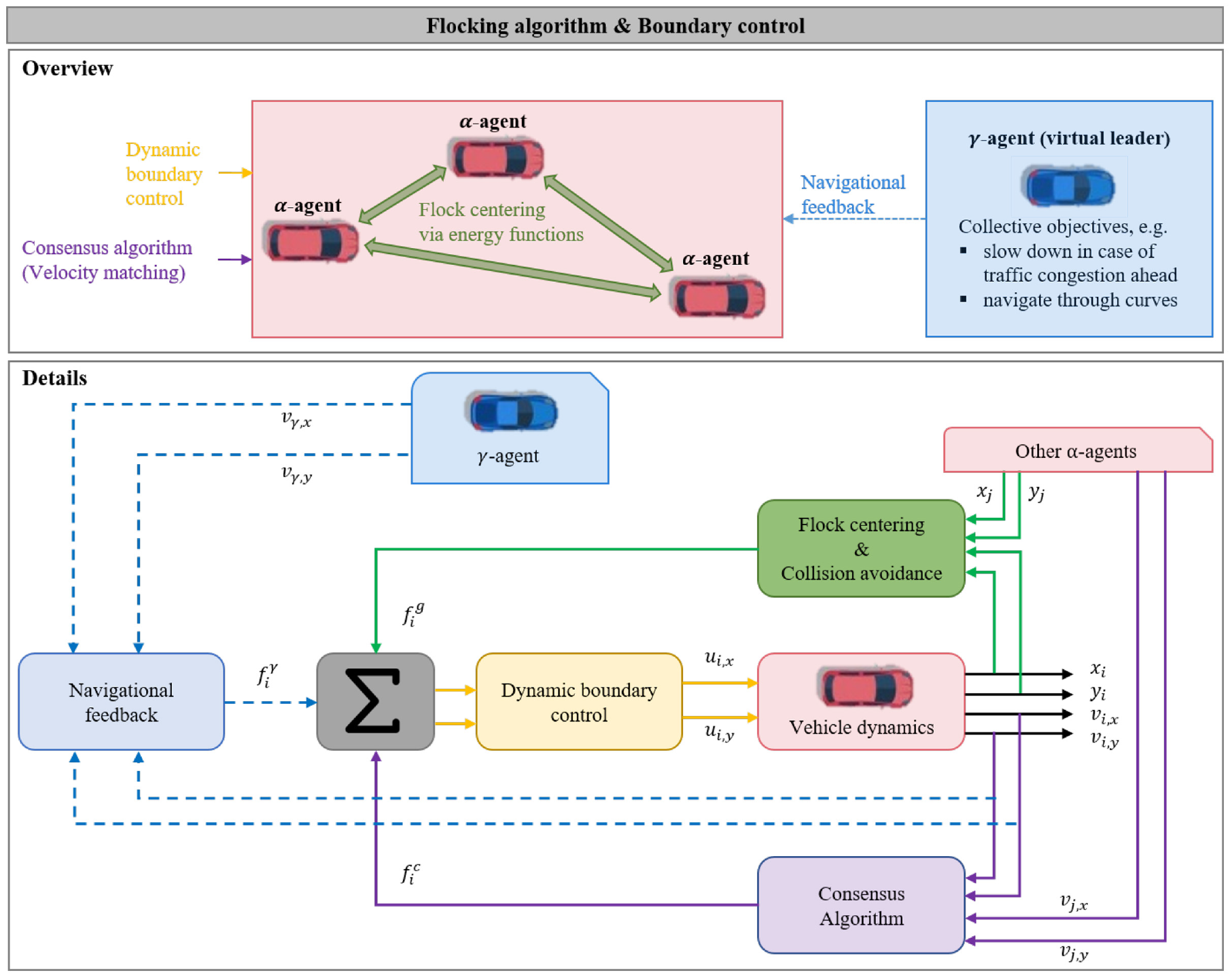
Overview of the methodology for vehicular flocking in lane-free traffic. (Color online only.)
In the following sections, the vehicle dynamics are first described, followed by the graph definition. The details of the control algorithm (along with the description of the bottom part of Figure 2) are given afterwards.
Basic Definitions
Vehicle Dynamics
In the lane-free environment, the lateral and longitudinal positions of the vehicle on a two-dimensional plane are considered as the vehicle output. As input commands, the vehicle is controlled by the respective accelerations in the longitudinal and lateral directions. The motion dynamics for a given vehicle


where


The longitudinal and lateral acceleration of vehicles are limited because of the physical capability of the vehicles for accelerating and breaking and, of course, because of the comfort issues of the passengers. In addition, since the movement of vehicles, specifically in highways, is essentially longitudinal, the decoupled Equation 1 is justified (
28
). However, to prevent inappropriate lateral maneuvers, the lateral speed is assumed to be bounded by the longitudinal speed as in Equation 2c, where
Flock Topology
The vehicle flock topology is modeled as a spatial graph. A graph

where
Flocking Algorithm
The flocking algorithm consists of three terms and is inspired by the work of Olfati-Saber (
41
). In his flocking theory, three types of agents are considered:


where
Definition of the Energy Function and Its Gradient
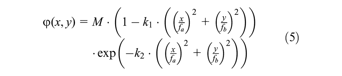
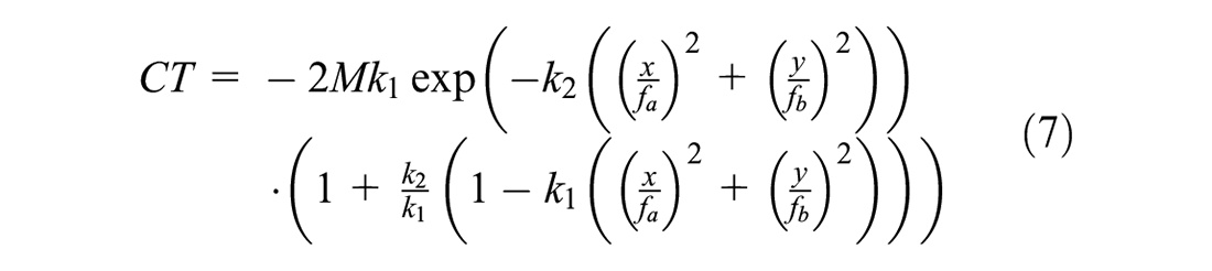
As mentioned in the background section, three simple rules define the collective behavior of a flock ( 32 ). In this paper, by defining a proper energy function, the first two Reynolds rules, that is, flock centering and collision avoidance with flock members, are realized. To this end, the two-dimensional Mexican hat function, originally proposed by Ricker ( 45 ) to describe the propagation of seismic waves, is used to model the energy function:
where
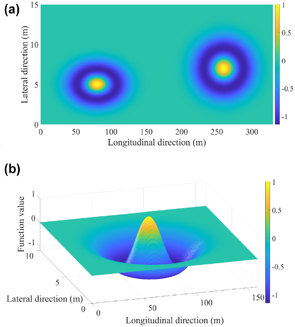
The Mexican hat function is used as the energy function for flock formation: (a) top view of two Mexican hat functions and (b) three-dimensional view of a Mexican hat function. (Color online only.)
The values of
Each vehicle


where
For any vehicle


where
Consensus Algorithm
In this work, the third Reynolds rule ( 32 ), that is, the velocity matching of the flock members, is carried out using the consensus algorithm in both longitudinal and lateral directions. In networks of agents (or dynamic systems), “consensus” means to achieve an agreement on a single target value with respect to a certain quantity of interest that depends on the state of all agents ( 40 ). In the following consensus algorithm, the speed of the vehicle is affected by the speed of other vehicles with the factor of their corresponding adjacency element. In Equation 9, we additionally normalize the consensus term to keep its value consistent with the other flocking terms in Equation 4. This approach leads to minimum variation in vehicle speeds within the flock. This implementation does not only harmonize the flock speed, but also dampens the speed perturbation of the flock members:


where
Navigational Feedback via a Virtual Leader
In addition to the location of vehicles in the flock and their relative speed, the overall path and movement of a vehicular flock should be controlled for several reasons, such as traffic efficiency and traffic measure purposes. To this end, a “virtual” leader as the
We assume that the dynamics of the virtual leader also follow the double integrator model given in Equation 1. Thus, the


where
Dynamic Boundary Control
It is crucial to bound the movement of all vehicles within the road boundary. In addition, a flock should not occupy the full lateral occupancy of the road. The boundary of the flock should be controlled, specifically when the flock should follow a pre-defined path to perform an overtaking maneuver or allow an emergency vehicle preemption, as indicated in Figure 1. Therefore, the need for efficient boundary control for the flock is essential. To this end, additional lateral acceleration constraints are required. This task may be addressed as a feedback control problem, whereby the left (right) road boundary is considered a reference value for all vehicles’ lateral movement ( 46 ). This control command specifies how much lateral acceleration is needed to lead the vehicle toward the boundary. This value is then assumed as the maximum acceleration and ensures that the vehicles never cross the boundary.
Assuming that


where

Note that the input arguments in the minimum function in Equation 14 have positive values, whereas the maximum function applies on the negative arguments.
Simulation Setup
To evaluate the proposed approach, a stretch of a ring road with 5 km length and 10.2 m width is developed in the software MATLAB as the traffic network. This network is illustrated in Figure 4. In addition to the permanent road boundary, a new dynamic flock boundary is defined that restricts the lateral movement of the flock. This boundary could be the result of a bottleneck, construction site, emergency vehicle preemption, or any other obstacle. The flock boundary is shown with a dashed red line in Figure 4. At the beginning of the simulation, vehicles are positioned randomly at the first section of the road with different initial speeds. For the
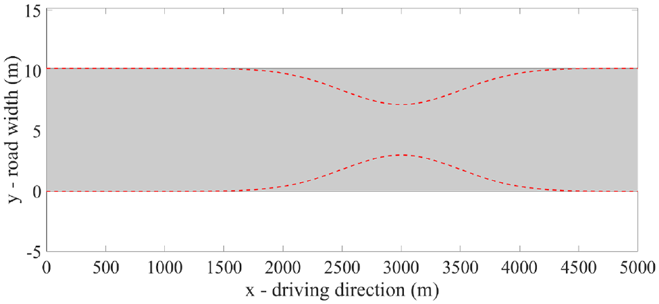
An overview of the considered traffic network. (Color online only.)
Without loss of generality and for the simplicity of evaluating the results, we assume five vehicles with random initial locations and random initial longitudinal speeds in the range of 15–35 m/s. The simulation duration is 5 min. The simulation results are shown and evaluated in the next section.
Results and Discussion
The simulation results are presented in the following with each section focusing on a different aspect. Firstly, it is shown how different input values and road boundaries lead to different flock formations. Secondly, the effect of the consensus algorithm is demonstrated. Afterwards, the impacts of the
Flock Formation
Firstly, the results of the flock formation are shown in this section for three different scenarios. Within the first scenario, an energy function with a larger ellipsoid area is chosen. The second scenario uses the same energy function, but exhibits a squeezed road boundary because of the possible use cases mentioned above (e.g., bottleneck). The third scenario uses an energy function with a smaller ellipsoid area under normal road boundaries. Figure 5 shows for all of the three mentioned scenarios that the implemented flocking algorithm successfully leads to the formation of vehicular flocks in lane-free traffic. In the figures, a flock of five vehicles is shown for each scenario. The size of the flock is also depicted. Note that, for consistency in the rest of this section, the vehicle numbering and coloring remain the same, as shown in Figure 5a. The figures clearly depict that, as intended, the vehicle arrangement within the flock formation remains the same in all scenarios, and only the longitudinal and lateral space gaps between vehicles, or consequently the flock size, change with changing boundaries or different sizes of the energy function. The values of
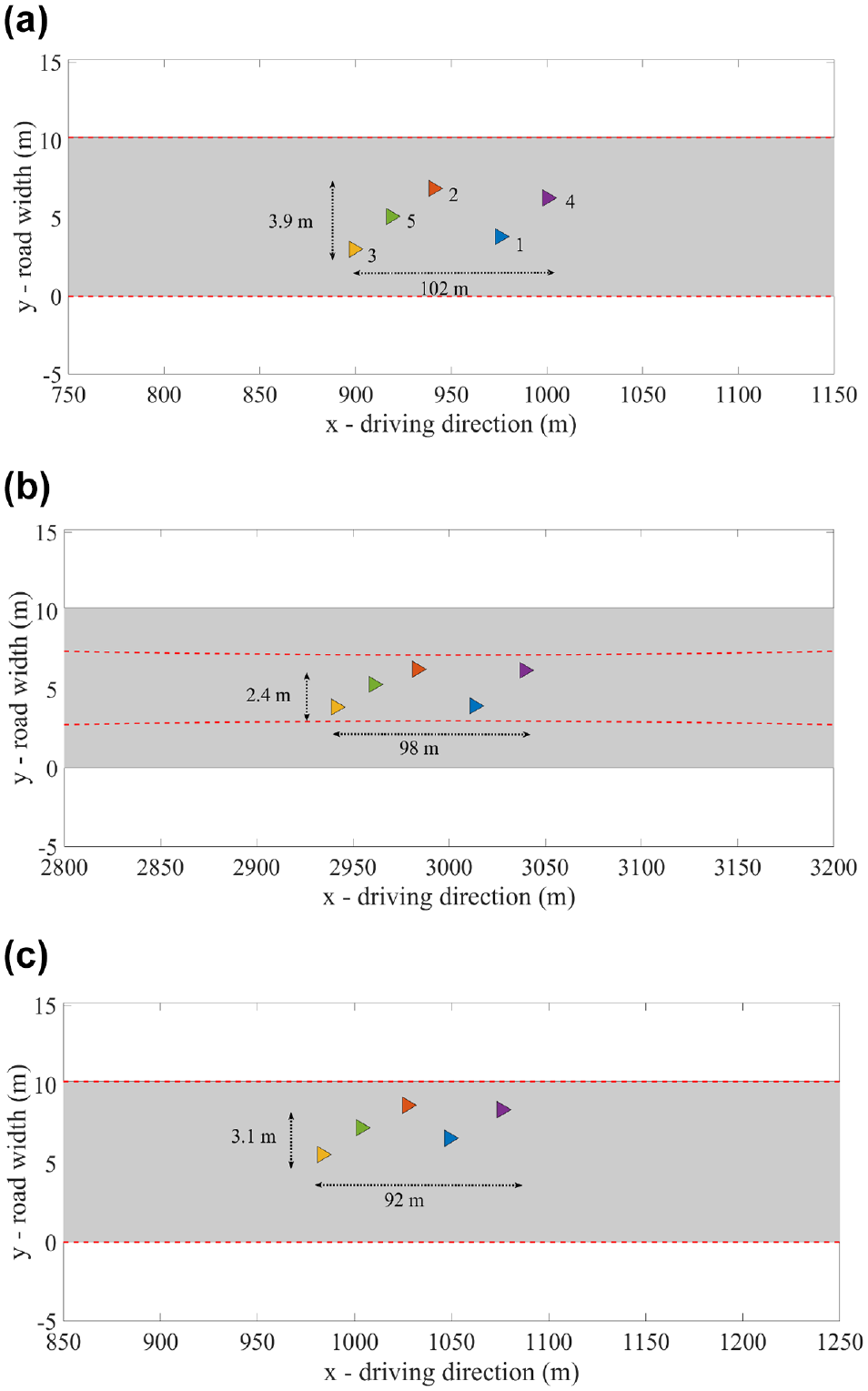
The location of vehicles within the flock depends on the size of the Mexican hat function and the road boundary: (a) location of vehicles with larger energy function (scenario 1), (b) location of vehicles at the squeezed boundary (scenario 2), and (c) location of vehicles with a smaller energy function (scenario 3). (Color online only.)
Velocity Matching
As mentioned in the methodology section, the consensus algorithm is used to perform the velocity matching of the flock. The longitudinal speeds of the vehicles at the very beginning of the simulation time are shown in Figure 6a. Initially, vehicles take different random speeds between 15 and 35 m/s, and just after a few seconds, they approach the agreed speed, which is, in this case, the speed of the
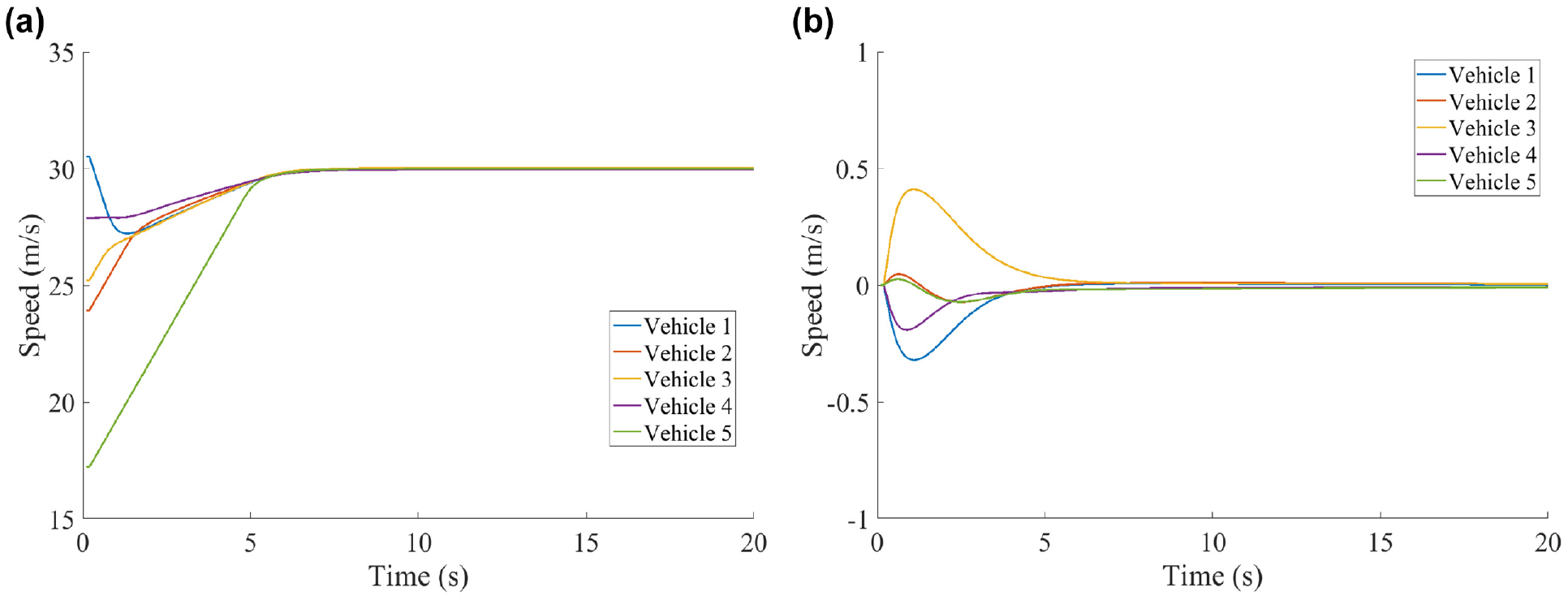
All the vehicles agree on a similar speed as the result of the flocking algorithm: (a) longitudinal speed of the vehicles and (b) lateral speed of the vehicles.
The vehicles’ initial lateral speed is zero and changes at the very first seconds because of the flock formation induced by the gradient-based term (see Equation 8). This fast convergence of the lateral speed also demonstrates the effectiveness of the used energy function.
Navigational Feedback
The third term in the flocking algorithm is based on the virtual leader, the
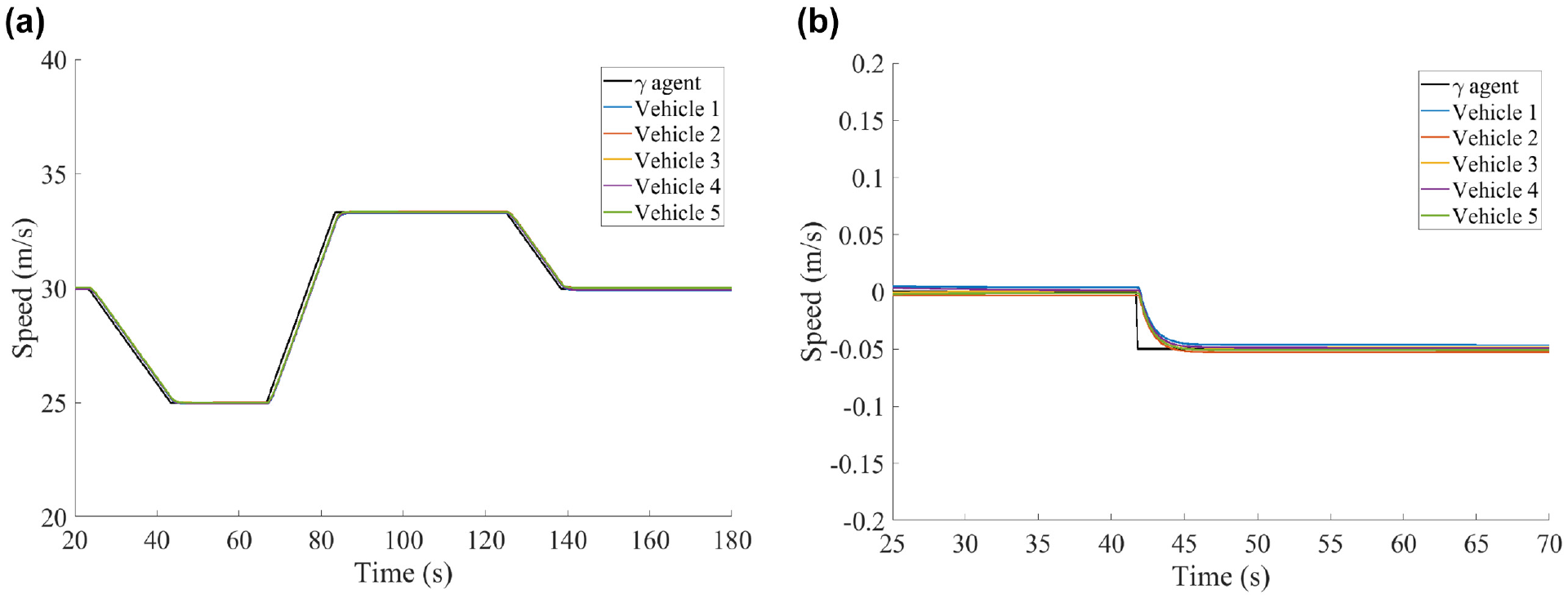
The speed of the vehicles follows the dynamics of the
In addition to that, in Figure 8, the lateral movement of all vehicles, as well as of the
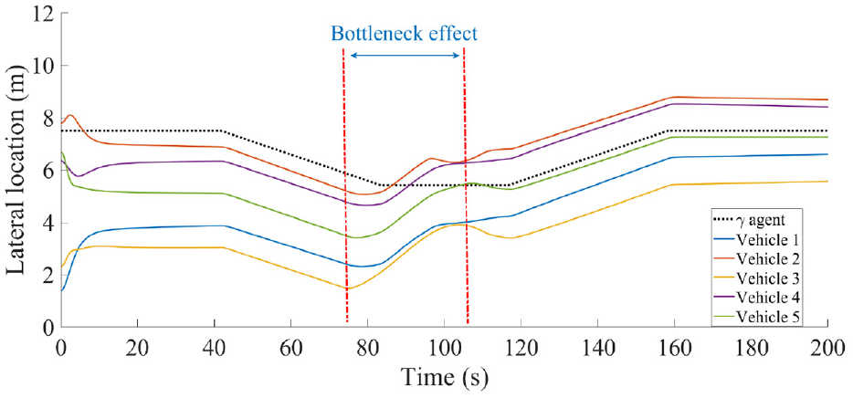
The lateral location of the vehicles follows the lateral movement of the
Flock Stability
Finally, we demonstrate the stability of the flock in the case of perturbation. At the time of 200 s, manual braking is applied to the front vehicle, that is, vehicle number 4. This braking is implemented by exerting a longitudinal deceleration of −2 m/s2 for a duration of 1 s. In Figure 9, the consequences of this perturbation on the other vehicles’ longitudinal and lateral accelerations and speeds are depicted. The results in Figure 9, a and b , shows that once the perturbation signal is released to vehicle 4, it takes the maximum possible longitudinal acceleration to recover its previous speed. More interestingly, it is noticeably visible that the other vehicles encounter tiny longitudinal acceleration and speed changes, demonstrating that the induced shock is dampened very efficiently. The dampening behavior is also illustrated in Figure 9, c and d , where the lateral acceleration and speed of the vehicles are shown. The flexibility of the vehicles within lane-free traffic to slightly change their lateral location compared to lane-based traffic reduces the negative and large longitudinal effect of the perturbation on the rear vehicles. In particular, the front vehicle, vehicle 4, and its predecessor, vehicle 1, drive in the opposite directions, alleviating the longitudinal perturbation consequences.
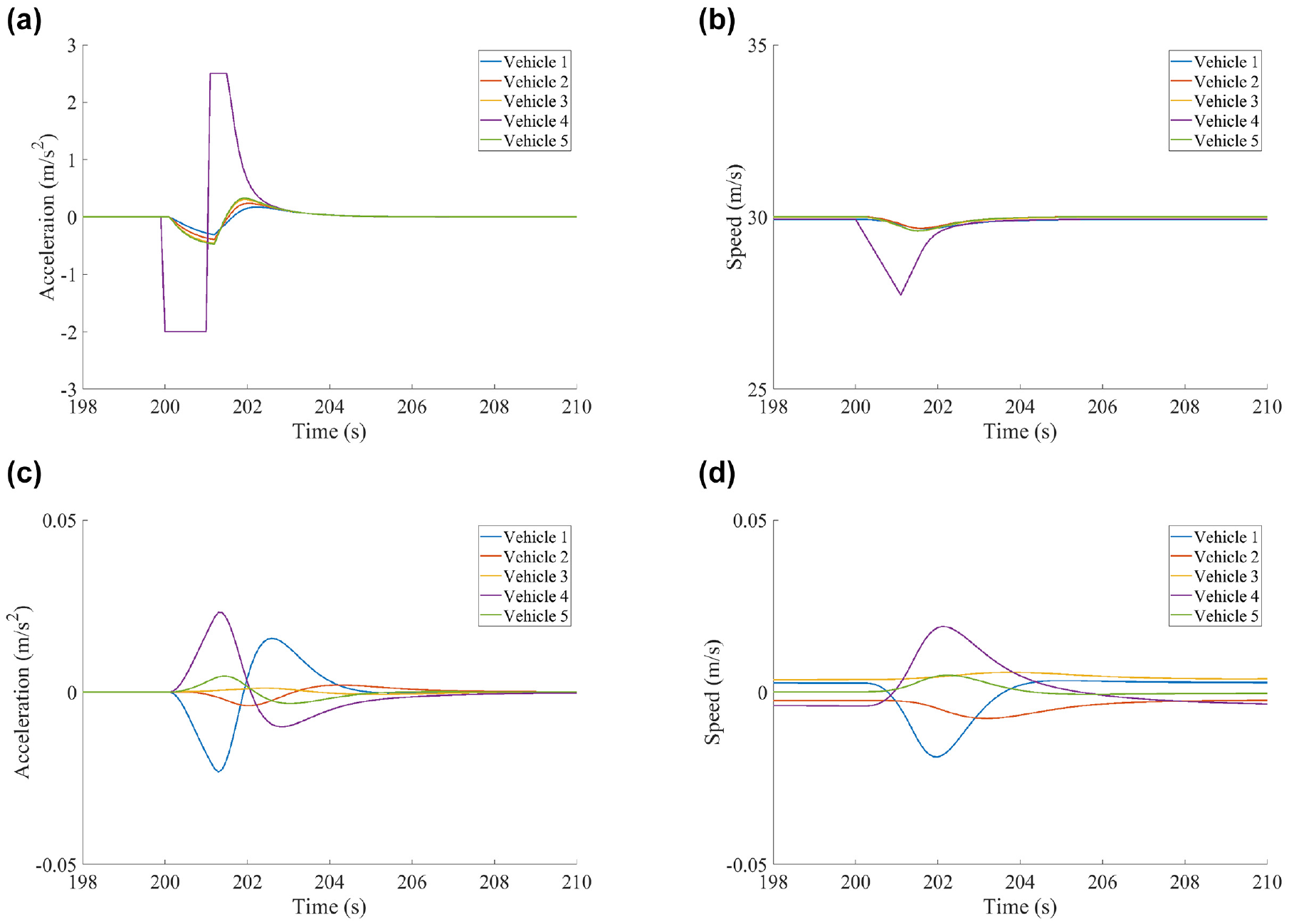
The vehicles go back to their equilibrium condition after the perturbation: (a) longitudinal acceleration of the vehicles, (b) longitudinal speed of the vehicles, (c) lateral acceleration of the vehicles, and (d) lateral speed of the vehicles.
Conclusion
Within this paper, we developed a new control algorithm for the flocking of automated vehicles in lane-free traffic that allows for achieving certain speeds, vehicle headways, and lateral distributions of vehicles on the road. The flocking algorithm is inspired by the work of Olfati-Saber et al. (
40
) and considers two types of agents:
The proposed approach was simulated for different scenarios within the software MATLAB with very promising results. Vehicular flocks were successfully and efficiently formed via energy functions within a few seconds and speeds aligned by the consensus algorithm. The flocks showed stable vehicle arrangements but changing sizes depending on the chosen energy functions and road boundaries. It was also demonstrated that the vehicles follow the trajectory of the virtual leader. Most importantly, we demonstrated the stability of the flock in the case of perturbation caused by a braking vehicle. The induced shock is dampened very efficiently as the vehicles are more flexible to slightly change their lateral location, which reduces the required longitudinal acceleration and speed changes.
Within future research, we would like to integrate an obstacle avoidance mechanism into our control algorithm. This allows us to implement the flock formation and movement in real traffic conditions with other non-flock vehicles. Until now, we did not control for specific vehicle arrangements within the flock, for example, to further minimize the aerodynamic drag in the case of side winds. This could be done by varying the orientations of the energy functions or by applying additional forces pushing the flock members to fixed positions inside the group. We also plan to implement the proposed flocking method within the traffic simulator SUMO. The implementation of flocks in a realistic traffic simulator paves the way for the evaluation of the impact of the flock formation on the road capacity and, additionally, exploitation of the flock as the traffic control measure.
Footnotes
Author Contributions
The authors confirm contribution to the paper as follows: study conception and design: M. Rostami-Shahrbabaki, S. Weikl, T. Niels, K. Bogenberger; data collection: M. Rostami-Shahrbabaki; analysis and interpretation of results: M. Rostami-Shahrbabaki, S. Weikl, T. Niels; draft manuscript preparation: M. Rostami-Shahrbabaki, S. Weikl, T. Niels, K. Bogenberger. All authors reviewed the results and approved the final version of the manuscript.
Declaration of Conflicting Interests
The author(s) declared no potential conflicts of interest with respect to the research, authorship, and/or publication of this article.
Funding
The author(s) disclosed receipt of the following financial support for the research, authorship, and/or publication of this article: This work is based on the project “Simulation and organization of future lane-free traffic” funded by the German research foundation (DFG), under the project number BO 5959/1-1.