
Abstract
This paper proposes a mode switching supervisory controller for autonomous vehicles. The supervisory controller selects the most appropriate controller based on safety constraints and on the vehicle location with respect to junctions. Autonomous steering, throttle and deceleration control inputs are used to perform variable speed lane keeping assist, standard or emergency braking and to manage junctions, including roundabouts. Adaptive model predictive control with lane keeping assist is performed on the main roads and a linear pure pursuit inspired controller is applied using waypoints at road junctions where lane keeping assist sensors present a safety risk. A multi-stage rule based autonomous braking algorithm performs stop, restart and emergency braking maneuvers. The controllers are implemented in MATLAB® and Simulink™ and are demonstrated using the Automatic Driving Toolbox™ environment. Numerical simulations of autonomous driving scenarios demonstrate the efficiency of the lane keeping assist mode on roads with curvature and the ability to accurately track waypoints at cross intersections and roundabouts using a simpler pure pursuit inspired mode. The ego vehicle also autonomously stops in time at signaled intersections or to avoid collision with other road users.
Keywords
There is an increasing demand for methods that will enable cars to drive with high levels of autonomy, while dealing with dynamical, control and safety constraints. This paper considers the mode switching control of autonomous vehicles with an emphasis on path following, under constraints on the trajectory including traffic light signals, road users and the need to maintain a safe distance from preceding vehicles. The application under consideration is the simulation of a vehicle navigating a distance of 500 m in a city environment, including cross intersections, roundabouts and traffic lights, before reaching a car park. Real-life driving scenarios often require hybrid systems with the ability to switch between controllers when the control objectives change. Mode switching is often implemented between adaptive cruise control (ACC) laws, as in Zhenhaia et al. ( 1 ) where cruise, following or approach modes were successfully selected with their distance, speed and acceleration references under real traffic conditions. Ioannou and Chien ( 2 ) developed ACC for platooning applications by implementing a switching logic in a look ahead model. Faster traffic flows were obtained compared with driver models. A similar headway switching logic was extended in Raza and Ioannou ( 3 ) to vehicle following and platooning in automated highway systems, with emergency situations handling. In Zhang and Ioannou ( 4 ), autonomous cruise control was further developed with the ability to change lanes and vary speed limits depending on the traffic conditions. In Kesting et al. ( 5 ), ACC was used together with a traffic dependent switching logic. In Hegyi et al. ( 6 ), model predictive control (MPC) was used for the optimal combination of flow metering and speed limits to reduce the overall congestion time. Platooning is beyond the scope of this paper, however. Here a time headway is only considered with respect to a maximum of one lead vehicle at any time. Other aspects of autonomy may involve the ability to avoid obstacles, using either MPC or path planning methods, such as jump point search (JPS) ( 7 , 8 ). Autonomous braking is increasingly considered because of its proven impact on driving safety through testing procedures ( 9 ). Autonomous braking algorithms often employ partial braking to decelerate, followed by full braking to avoid collision, as in Bae et al. ( 10 ) where a tradeoff was achieved between ride comfort and safety. In Kusano et al. ( 11 ), a 39% reduction in the number of fatal injuries was obtained by combining forward collision warning with autonomous braking. This capability was extended in Lee et al. ( 12 ) to the ability to brake autonomously on roads with curvature. Autonomous driving strategies were also developed to account for traffic light signals. Predictive cruise control was used in Asadi and Vahidi ( 13 ) where upcoming traffic signal predictions were exploited to improve fuel economy and reduce trip time by adjusting speeds to reach intersections when traffic lights turn green. In Kamal et al. ( 14 ), MPC was used to optimize fuel economy on roads with signalized intersections.
This paper focuses on path following on roads with curvature and signalized intersections with the ability to stop but also restart autonomously. Lane keeping and maneuvering using MPC methods has been the subject of increased research interest in recent years. Predictive control is also increasingly being considered using active set or interior point methods, with hybrid affine models where a mode is typically selected based on the discrete states of a state machine and on discrete events being triggered when those states exceed thresholds ( 15 ). In Abdelmoniem et al. ( 16 ), a Stanley lateral MPC controller was used to optimize lateral and yaw errors, while avoiding obstacles during double lane changes. In Xu et al. ( 17 ), MPC was performed with autonomous lane keeping using lane keeping assist (LKA) sensor points. Other approaches have focused on reducing computational demand using an explicit MPC approach where a multiparametric quadratic optimization problem is solved offline. This allows for pre-computed gains to be used in different state space regions for real-time implementation, as shown in Lee and Chang ( 18 ) and Kamat ( 19 ). Nonlinear and time varying MPC were also used in Falcone et al. ( 20 ) to maintain stability during active steering control on slippery roads up to relatively high speeds.
The ability to adapt MPC to unexpected emergencies or to changing paths constraints is important to many driving scenarios in city environments. The latter was shown in Bujarbaruah et al. ( 21 ), where adaptive MPC was used to control the steering at constant speeds using a set membership-based switching strategy to deal with curvature changes during autonomous lane keeping. In Qu et al. ( 22 ), MPC was used with five driving modes depending on a congestion dependent emergency coefficient and on the estimated acceleration of a lead vehicle, with improvements compared with single mode MPC in driving comfort and safety. In Xue et al. ( 23 ), adaptive MPC was used for automated fallback maneuvers in presence of sensor malfunctions. Adaptive MPC formulations with responsibility-sensitive safety distance constraints were introduced in Chai et al. ( 24 ). The robustness of adaptive MPC to scenario linked uncertainty, including driving at a junction, was investigated in Leurent et al. ( 25 ). A chance constrained scenario MPC approach was used to change lanes safely in Cesari et al. ( 26 ). MPC was used in Liu et al. ( 27 ) for path planning by enforcing collision avoidance constraints while maintaining driving comfort by incorporating a lane dependent potential field within the cost function. A hybrid MPC approach was used as an ACC method in Corona et al. ( 28 ) where the objective was to follow a lead vehicle. In Di Cairano et al. ( 29 ), a switched MPC controller was developed to switch between local linear MPC controllers depending on tire conditions. A switched MPC controller was also proposed in Sun et al. ( 30 ) with mode switching between tracking error models, respectively based on heading error, heading error rate and sideslip. Mode switching with simpler controllers is less common, with few exceptions as in Shakouri and Ordys ( 31 ), where ACC uses nonlinear MPC for throttle control and more reactive proportional plus integral (PI) control for the more urgent autonomous braking and an additional switching logic is used to transition automatically from driver commands to ACC. The switching between MPC controllers is therefore increasingly considered, but mode switching between MPC and simpler, more reactive controllers has not received sufficient attention. Another reason to switch to more reactive controllers is the known possible adverse effect of certain sensors, such as LKA systems, as reported by Thatcham Research in Grover et al. ( 32 ) for scenarios requiring a lane change or to stop following lanes. In this paper, mode switching is applied between adaptive MPC and a simpler pure pursuit controller, which is known to be efficient at low speeds. In pure pursuit, a virtual target is assumed. The steering command is then calculated either from a required curvature and look ahead distance from the vehicle’s rear axle to the virtual target position, as in Yang et al. ( 33 ), or from a line of sight (LOS) requirement from the center of gravity (CoG) of the vehicle to the virtual target, as in Chen and Zhu ( 34 ). In this case, the car model still accounts for steering commands being applied with the front wheels, while heading is defined from the CoG.
The main contributions of the paper are as follows:
A mode switching cruise and steering controller is applied with an adaptive MPC LKA mode on the main road to optimize path following and a safer and more reactive waypoints-based linear pure pursuit controller at road intersections, where this simpler approach is known to be efficient because of the shorter distances and lower speeds at those locations.
The mode switching controller only uses LKA sensors on the main road where they are safe. It uses waypoints instead of LKA sensing at road junctions including cross intersections and roundabouts, where the discontinuities in lane patterns otherwise present the safety risk of an interruption in LKA sensor data, potentially leading to a wrong lane, even assuming a large LKA sensor field of view (FoV). Driving at junctions using LKA indeed presents lane keeping safety risks similar to the ones reported in Grover et al. ( 32 ).
An autonomous braking logic is proposed, which differentiates between stopping accurately for traffic lights and emergency braking for other road users (ORUs) with additional safety margins, followed by a safe restart mode in both cases.
The pure pursuit law projects the heading toward a virtual target between the current and next waypoints, which exploits ideas from driver models and differs from conventional LOS pure pursuit where the next waypoint is tracked.
The solutions are developed using features of the Automatic Driving Toolbox™ in MATLAB®/Simulink™ 2020a, including LKA, optical and radar sensors and Model Predictive Control toolbox libraries, as well as the Driving Scenario Designer app. It is noteworthy that the LKA block in Simulink™ systematically fails at junctions and that the proposed approach circumvents this issue, which opens new prospects for users of the Automatic Driving Toolbox™ in MATLAB®, particularly for path following. The supervisory mode switching control, pure pursuit inspired mode and autonomous braking algorithms were all developed as part of the InnovateUK Assured Parking project (reference: 105095). One of the objectives of the project is to evaluate and develop city driving and parking capabilities for autonomous vehicles. The road model has similar features to the ASSURED CAV City at the HORIBA MIRA campus, Nuneaton, UK. A desired itinerary is realized using waypoints centered on the desired lanes with desired speeds, based on speed limits and arcs connecting waypoints on the roads that intersect.
The remainder of this paper is organized as follows. The equations of vehicle dynamics are described in the next section. The supervisory switching logic is introduced in the following section for the autonomous driving problem under consideration. A mode switching steering controller is then presented before being extended to steering and speed control. An autonomous braking controller is introduced as an additional control mode to stop for traffic lights or ORUs before restarting. The numerical simulation analysis is then presented, which demonstrates the effectiveness of the proposed mode switching controller with adaptive LKA MPC and pure pursuit waypoint tracking modes for path following on roads with curvature, cross intersections and roundabouts and of the autonomous braking mode using onboard obstacle sensing and traffic light information. This is followed by a discussion on the generality of the approach before concluding the paper.
Equations of Vehicle Dynamics
The lateral and longitudinal vehicle dynamics are described by a “bicycle” type model similar to the one in Falcone et al. ( 20 ) and given by:
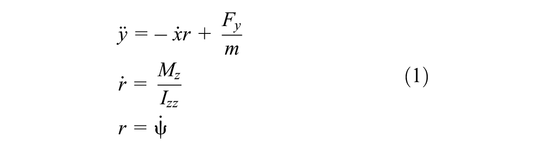

where

where
The model can be compactly written in vector form as:

with:

For convenience,
Supervisory Mode Switching Decision Layer for Autonomous Vehicle Control
The autonomous car in this study is required to perform the following autonomously:
Switch between adaptive MPC and linear pure pursuit inspired waypoint tracking using the Autonomous Steering and Acceleration Supervisory Controller (ASASC) described in Algorithm 2 to drive on roads with junctions and only use LKA when it is safe. Note that the Steering Controller Arbitrator (SCA) of Algorithm 1 assumes steering at a constant speed and was developed as a control design stage before being extended to ASASC.
Brake using the Multi-Stage Autonomous Braking System (MS-ABS) described in Algorithm 3 to adhere to road traffic regulations and stop in the case of emergency caused by the presence of ORUs in the path of the vehicle. The obstacle detection and pose estimation were obtained using sensor fusion from optical and radar sensors at the front of the ego vehicle.
Restart when the traffic light is green or when the way is clear again, also using MS-ABS.
The supervisory decision layer determines which of the acceleration, steering and braking controllers are activated based on three sets of activation thresholds:
Thresholds specifying forward crossing/collision warning time
Thresholds specifying the time gap
Lane keeping thresholds l and lc to impose vertical deviation constraints and to indicate if LKA sensing is safe to use, respectively.
A forward collision warning (FCW) status variable determines if, without deceleration, collision with another road user will occur. Likewise, a forward stop line crossing warning (FSLCW) status variable determines if the traffic line will be crossed when the light is amber or red. The calculation of FCW time is described in the multi-stage braking section. The positions of the vertices of quadrilateral road intersection areas at the junctions are assumed to be obtained using the onboard map. Those regions will be taken to be rectangular in the numerical simulation section. The supervisory algorithm can be summarized as follows for scenarios requiring steering, acceleration and braking commands:
FCW status = 0 (No FCW)
FSLCW = 0 (No FSLCW)
braking status = 0 (No braking)
call the mode switching controller for steering/acceleration (ASASC, Algorithm 2)
call the autonomous braking controller (MS-ABS, Algorithm 3)
Note that within MS-ABS (Algorithm 3), FCW status will be set to 1 before braking status is set to 1 (autonomous braking). The throttle in ASASC (Algorithm 2) is then set to 0 during multi-stage braking. When the braking status is reset to 0 (green light), the brakes are released, and the throttle command of ASASC is reactivated. A finite state machine enables the car to start again when the light turns back to green and if there is no obstacle in front of the vehicle.
Mode Switching Control for Path Following with Steering Inputs
The control design for the autonomous vehicle control is done in stages, where the lane following is first formulated for steering at constant speeds before being extended to acceleration and steering commands. The mode switching steering controller, which is presented in this section, has two modes: a LKA MPC controller on the main road and a waypoints tracking pure pursuit inspired steering controller at road intersections. The next two subsections respectively describe the adaptive MPC mode and the pure pursuit inspired waypoints tracking mode in the constant speed case.
Adaptive MPC Steering Controller Mode
This subsection is a precusor to the steering and acceleration controller. It focuses on steering and assumes that the speed is constant, making it possible to evaluate the steering performance independently. This preliminary simplifying assumption will be relaxed in the proposed 3DoF controller.
A reduced order control system is therefore considered first, with

where
Using adaptive MPC, it is possible to incorporate controller and state constraints. The prediction model is adapted to changing operating conditions. The plant model is linearized by a first order Taylor expansion around operating points

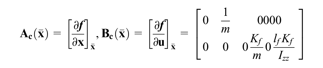
The matrix Cc is
The predicted states for i = 1, N where N is the prediction horizon, can then be written as a function of past states over a prediction horizon and past control inputs over a control horizon Nc:
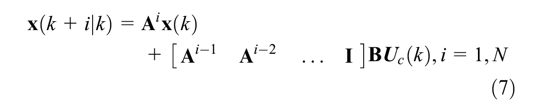

where
For
Pure Pursuit Steering Controller Mode
The conventional stabilizing steering controller at cross intersections or when entering and leaving roundabouts in the constant speed case will simply consist of a PI controller:
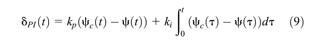
where kp and ki are the proportional and integral controller gains, respectively, and
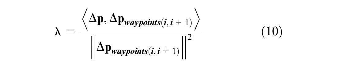
where 〈.,.〉 represents the scalar product,

where

where
The waypoints are taken to be at the center of the desired lane on the road map and on the arcs joining roads at road intersections. The desired speed is constant. This condition will later be relaxed with the variable speed controller and the same pure pursuit law will be used to track variable (piecewise constant) desired speeds. In the next subsection, the constant speed mode switching steering controller will combine the two controllers from the last two subsections.
SCA
The objective of steering control is to follow a desired path including junctions and only change steering with a constant speed. The mode selection switches to the adaptive MPC steering controller mode on the main road before reaching road intersections, whenever the lane keeping MPC and waypoint tracking are sufficiently different (above safety threshold
A set-based approach is used to define road intersection areas where pure pursuit PI control is used. Let F denote the full road map, in other words

where
The mode switching steering algorithm is summarized below:
Algorithm 1: SCA Algorithm
In the SCA, steering control is applied at a constant speed to evaluate the steering performance independently from speed control and uses adaptive LKA MPC mode in
Apply adaptive MPC ,
Apply the waypoint tracking PI pure pursuit controller of Equation 9
Mode Switching Controller with Steering and Acceleration Commands
The mode switching controller of this section also has an adaptive MPC LKA mode and a linear waypoint tracking pure pursuit mode; however, both control modes have two inputs, steering and acceleration. The state vector
The control objective of ASASC (Algorithm 2) is to follow a desired path with variable desired speeds when necessary (i.e., linearly decreasing desired speeds at the junctions when leaving the previous road or roundabout and linearly increasing desired speeds when entering the next road or roundabout). The ego vehicle will also maintain a safe minimum distance headway
Adaptive MPC Steering and Acceleration Controller Mode
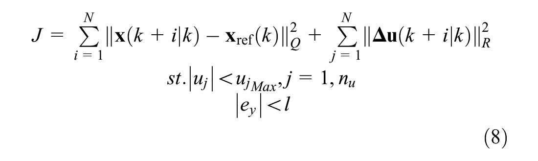
The adaptive MPC algorithm will be identical to the one in Equations 6 to 15, but with additional constraints.
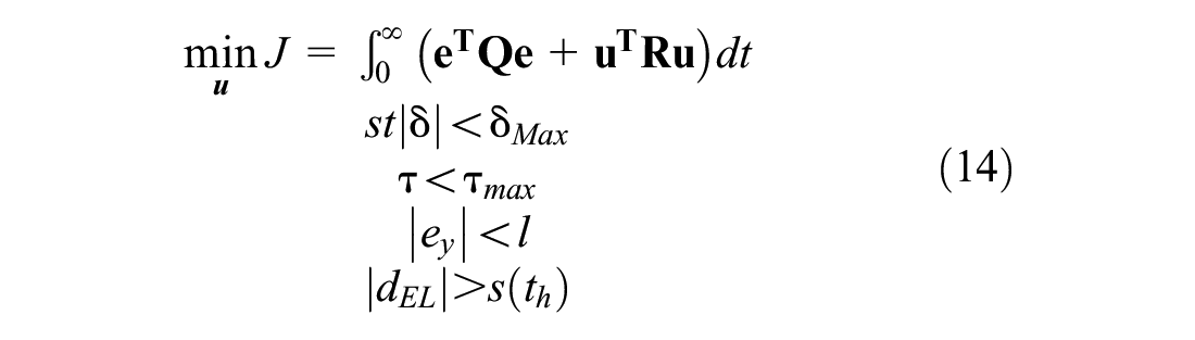
where l is an upper bound constraint on the cross track error
Linear Steering and Speed Controllers in the Waypoints Tracking Mode
The conventional steering control law for the 3DoF controller is still given by Equation 9 and the controller for longitudinal speed
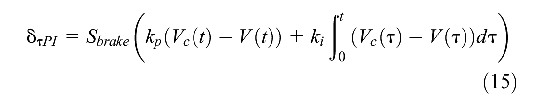
where
Note that the throttle will be multiplied by a status variable
The 3DoF mode switching algorithm, summarized in the ASASC (Algorithm 2), uses steering and acceleration commands to control speed, position and heading.
Algorithm 2: ASASC
This algorithm only runs when MS-ABS (Algorithm 3) is not running (FCW status = 0, braking status = 0). For compactness,
Apply adaptive MPC
Apply waypoint tracking PI controllers from Equations 9, 15
Note that in the adaptive MPC mode, the control input vector
Autonomous Braking with Start–Stop Sequencing
The traffic light signals are programmed as a periodic finite state machine sequence. The proposed MS-ABS mode can be activated at any time to allow the car to stop for road users in the path of the ego vehicle, detected using optical and radar sensors, or to stop for traffic lights when necessary. The vehicle is also programmed to restart when the traffic lights turn back to green or when there are no more road users in the path of the ego vehicle. The methodology and algorithms for autonomous braking and start–stop sequencing are detailed hereinafter. Without loss of generality, autonomous braking is assumed to take place on straight parts of the road circuit, which is a realistic assumption near traffic lights. Autonomous braking is implemented using a finite state machine to select realistic progressive deceleration stages in the range from 0 to 1 g, with values above 0.4 g considered as hard braking.
Multi-Stage Braking Algorithm
The algorithm is activated when a time to collision (TTC) or time to traffic light (TTTL) becomes shorter than the forward collision/intersection warning time. The FCW and FSLCW times are given by:


where V is the norm of vector

The division by two in Equation 17 is sometimes overlooked in commercial software but is necessary to stop at the correct position. Indeed, for a constant deceleration stage to reduce the initial speed

where

where k is a gain that can be tuned empirically and depends on the speed limit and the detection sensors’ specifications. Geometrically, detection is possible if the ORU is within the sensor FoV and range
The autonomous braking algorithm for ORUs in Algorithm 3 is otherwise very similar to stopping for traffic lights, with the differences being that TTTL is replaced by the TTC and that the restart condition (light turning back to green) is replaced by a condition to check that the road user has been outside detection range for more than a set time, trestart.
The multi-stage braking algorithm is summarized in Algorithm 3 as follows:
Algorithm 3: Multi-Stage Autonomous Braking Algorithm (MS-ABS)
This algorithm is run:
If (traffic light is amber or red and
If an ORU is suddenly detected and emergency braking is required.
There is an additional 0.1 s detection time delay to detect traffic lights or ORUs. That delay is implemented by default within the Automatic Driving Toolbox radar and optical sensors blocks in the case of road users and was verified with HORIBA MIRA to be realistic. To account for this and stop before the traffic light stop line, the car stop line is taken to be −0.5 m before the traffic light stop line. Let n be the number of braking stages.
FCW status = 1 or FSLCW = 1 (collision or stop line warning, autonomous braking algorithm activated)
(use Equation 17 to compute
otherwise use Equation 19)
Braking status = 1 (Deactivate throttle controller of Algorithm 2:
FCW status = 0
FSLCW = 0
Apply
D = 0 (Disable autonomous braking)
Braking status = 0 (Reactivate throttle controller of Algorithm 2)
Note that for single stage braking (n = 1) in the MS-ABS, the condition to compute TTTL (or TTC) is:

where D is the nominal deceleration value (typically 4 m.s−2). In the simulation analysis, only longitudinal axis components of vectors
The autonomous braking algorithm was implemented using Stateflow™ and MATLAB®/Simulink™ to implement the state machine part of the logic that differentiates between the cases of traffic lights and ORUs.
Numerical Simulation Analysis
The vehicle parameters used for the simulation analysis are mass, m = 1575 kg, yaw inertia, Izz = 2875
The path following objective is to track a desired trajectory with waypoints centered within the lane. This is done using adaptive MPC when LKA is enabled on the main road (F\
Obstacle detection sensors with moderate technical specifications are only used in scenarios 2 and 3 where speed is variable. The radar sensor on the vehicle has a range of 100 m and a FoV of 19.85 degrees to detect lead vehicles at a relatively close range. The optical sensor has a larger FoV of 43.6 degrees and a range of 150 m. Those technical specifications are within the usual range for modern obstacle sensors in autonomous vehicles, see Müller ( 35 ). The sensor detections were derived for realistic simulated pedestrian motion, which was defined using the Driving Scenario Designer app.
Scenario 1: Switched Controller with Lane Keeping MPC Steering and Waypoint Steering Modes
For this scenario, the SCA (Algorithm 1) is used and simulation time of
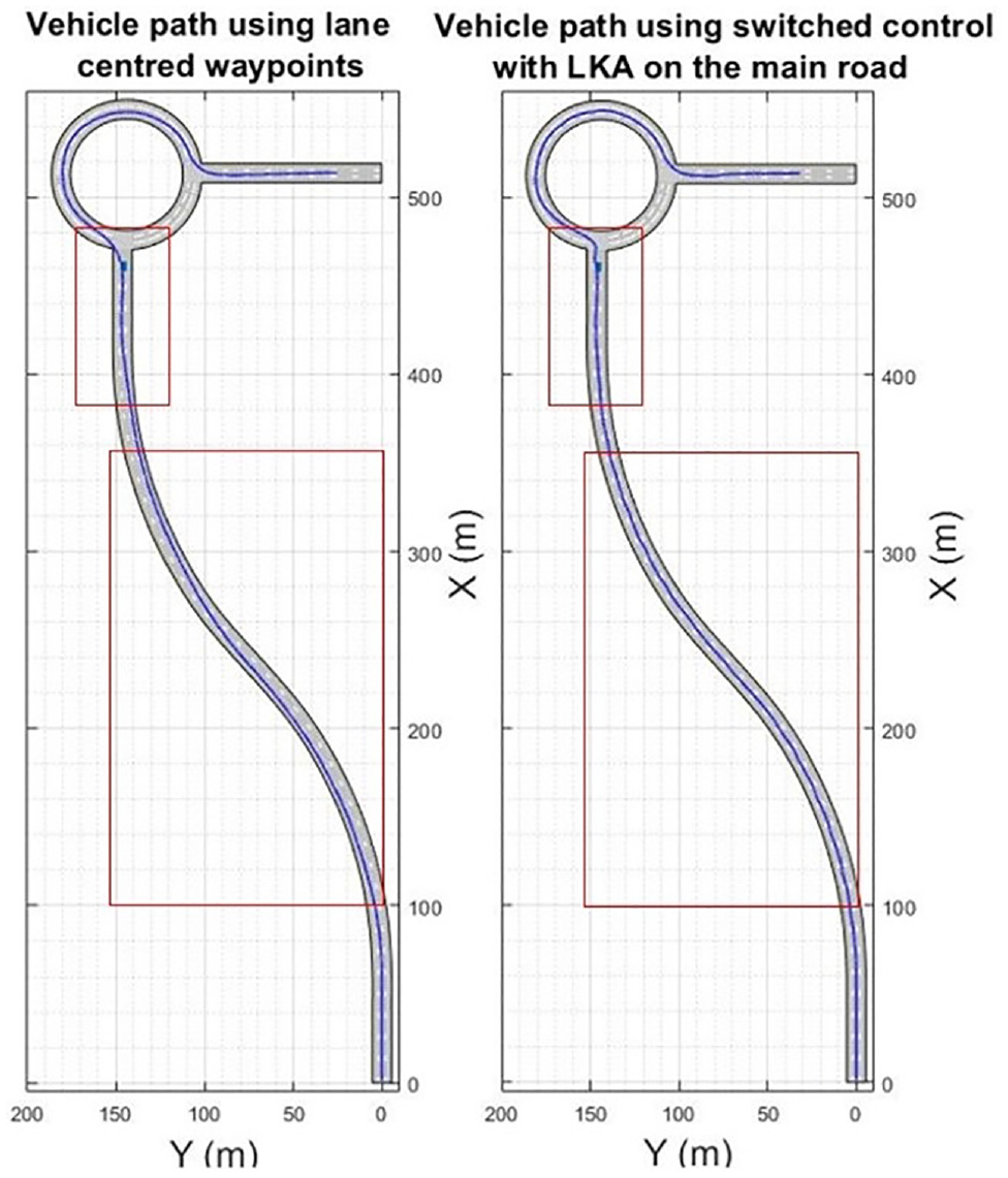
Comparison between waypoint tracking (a) and lane keeping assist (b) as an adaptive model predictive control (MPC) mode for Algorithm 1 on the main road: (a) vehicle path using lane centered waypoints, (b) vehicle path using switched control with lane keeping assist on the main road.
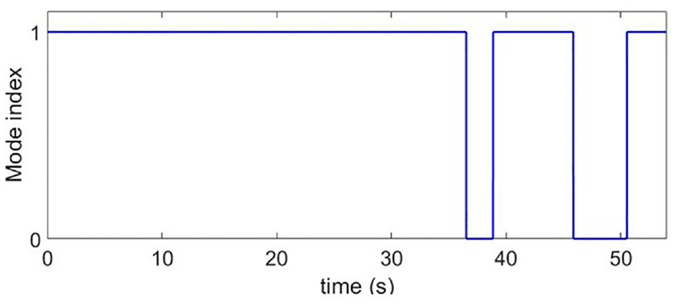
Mode index for steering only control, where 1 indicates that lane keeping assist model predictive control (LKA MPC) is activated and 0 indicates that waypoint tracking is activated.
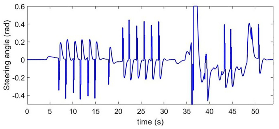
Steering angle input using the switched steering controller.
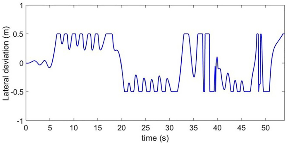
Lateral deviation using the switched steering controller.
In Table 1, the performance metrics show that the use of the mode switching controller with adaptive MPC and linear stabilizing modes has enhanced efficiency in both lateral integrated absolute error (IAE)
Performance Metrics for the Switched Steering Controller Simulation with and without Lane Keeping Assist (LKA) on the Main Road
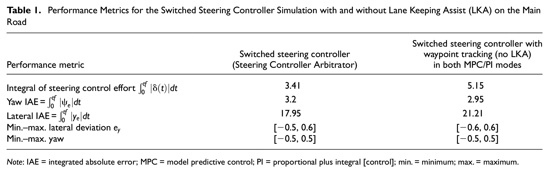
Note: IAE = integrated absolute error; MPC = model predictive control; PI = proportional plus integral [control]; min. = minimum; max. = maximum.
Scenario 2: Switched Controller with Steering and Acceleration Inputs in MPC and Waypoint Tracking Modes
In this subsection, ASASC is used and speed is controlled to a target speed history, which is constant at 21 m.s−1 on the main road (47 mph) or adjusted to keep a safe distance from the lead car. Desired speeds at the cross intersection consist of a linear deceleration when approaching the junction followed by a linear acceleration out of the junction. The full simulation uses 29 waypoints in total, including waypoints on the main road in case LKA sensing failed and waypoints at the junction. The additional constraints compared with scenario 1 are a prescribed time headway
The car is shown to follow the road curvature at the center of the lane and turns at the junction where the lanes are discontinued before joining the correct road and lane and reactivating LKA. The MPC weights on longitudinal tracking, change in acceleration and steering commands are all equal to 0.1, whereas the weight on lateral error is equal to 1. The prediction horizon is 3 s, the control horizon is 0.2 s, the sampling time period is 0.1 s. The gains of the PI controllers are kp = 1, ki = 0.05 for steering and kp = 1.1, ki = 0.1 for speed control. Figure 5 shows that the ego car follows the road curvature accurately and remains centered on the lane. In Figure 6, the mode switching controller is shown to perform better when the adaptive MPC mode uses LKA sensing compared with the use of waypoints during that mode on the main road. The same waypoint tracking pure pursuit controller is used at the junction in both cases. Note that LKA simply cannot be used for comparison at junctions using the Automatic Driving ToolboxTM. It was indeed found that LKA sensing systematically fails at junctions, which would also be the case in practice, because of lane discontinuities and lane recognition issues, even with a wide LKA sensor FoV. Using waypoints at junctions is therefore a safety improvement.
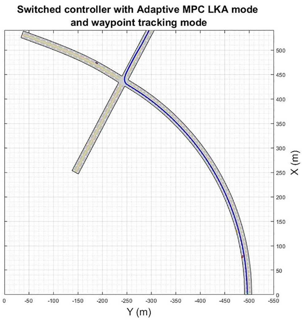
Path following on curved trajectory with a junction using the switched 3DoF controller.
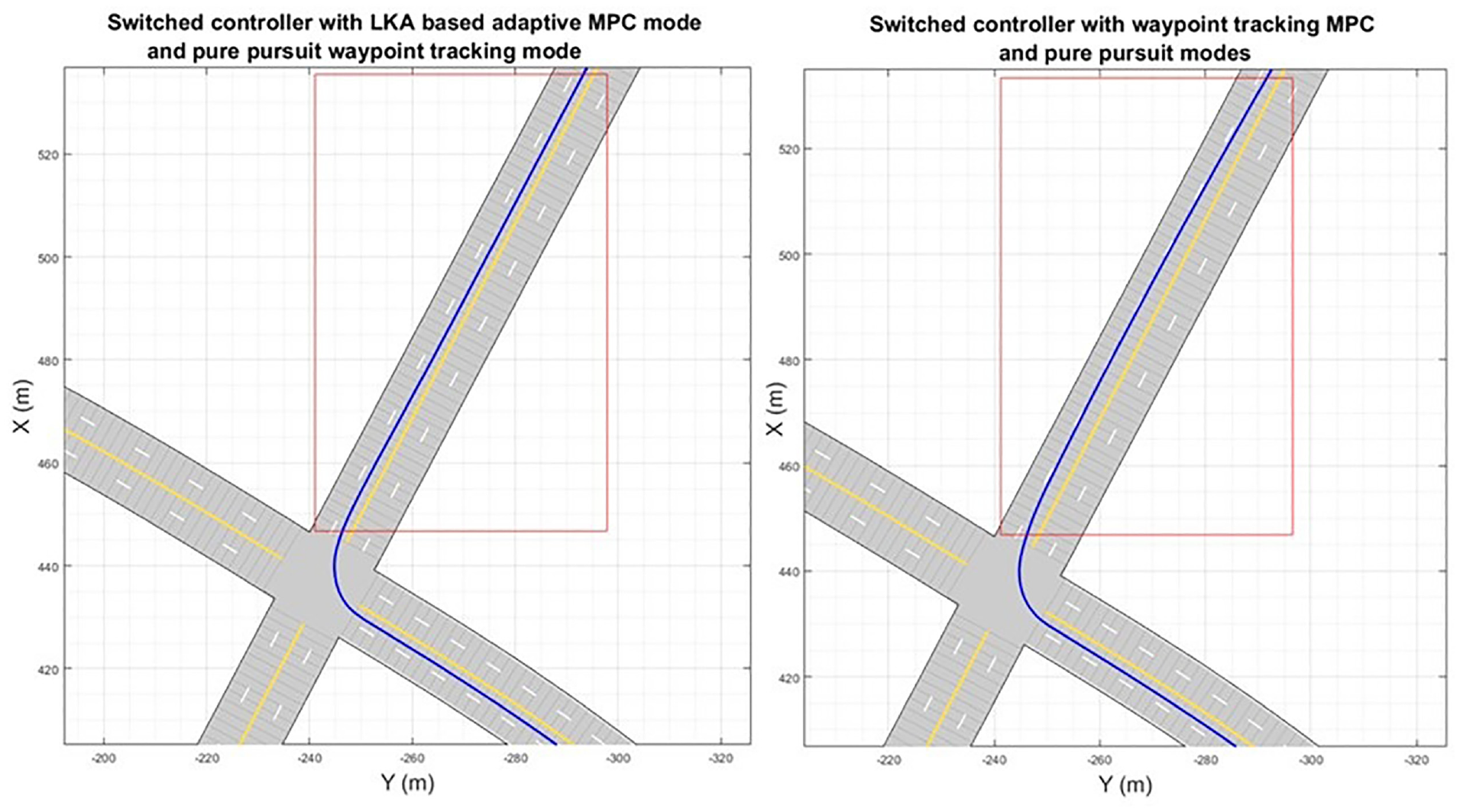
Comparison at the intersection between lane keeping assist (a) and waypoint tracking (b) as an adaptive model predictive control (MPC) mode for Algorithm 2 on the main road.
In Figure 7, the ego vehicle remains above the prescribed safety distance using MPC while the lead vehicle is detected. The control logic switches from mode index = 1 to waypoint tracking (mode index = 0) for 1 s at time t = 31 s, when the ego vehicle reaches the junction, before LKA is enabled when the ego vehicle exits the junction. Figure 8 shows that the acceleration commands remain within the prescribed maximum acceleration limits of +/−2 m.s−2. Figure 9 shows that gentle steering commands are used by the adaptive MPC controller mode of ASASC (Algorithm 2) compared with the steering only controller of Algorithm 1 (SCA); steering then reaches and recovers from a peak in steering but remains within prescribed steering constraints. In Figure 9, the lateral deviation remains within +/−0.5 m.
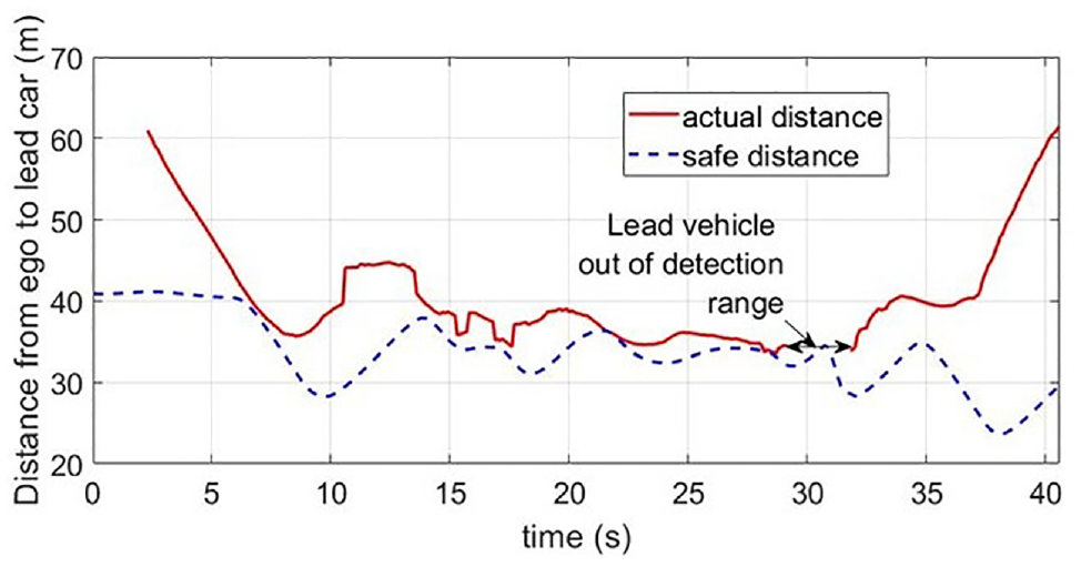
Distance to lead car and safety distance.
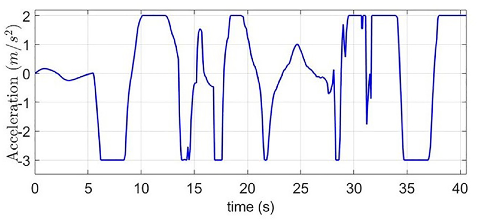
Acceleration commands using the 3DoF switched controller.
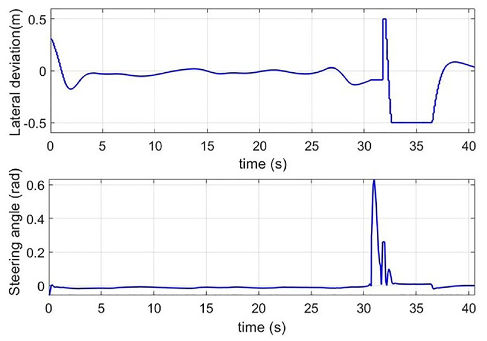
Lateral deviation (a) and steering angle (b) using the 3DoF switched controller (in radian).
All controller constraints were met during the MPC stage. A linear speed deceleration and acceleration profile was used when entering and exciting road junctions. In Table 2, good tracking performance is obtained by adding speed control to the mode switching controller. The MPC LKA stage is more accurate, as predicted, in yaw and lateral control, but the performance of the controller remains acceptable in integrated control inputs and tracking error when the linear stabilizing control mode is incorporated in the full simulation.
Performance Metrics for the Switched Controllers with Steering and Acceleration Commands
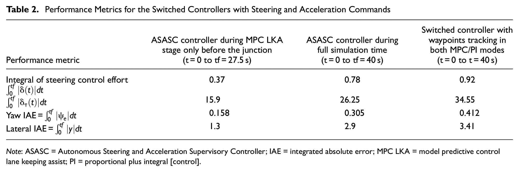
Note: ASASC = Autonomous Steering and Acceleration Supervisory Controller; IAE = integrated absolute error; MPC LKA = model predictive control lane keeping assist; PI = proportional plus integral [control].
Scenario 3: Autonomous Braking for Traffic Tights and a Pedestrian
In this scenario, MS-ABS (Algorithm 3) is used on a straight road along the Y-axis of the driving circuit. The traffic light stop line y-position coordinate is 8 m and the initial ego car y-position is at −30 m. The traffic light is located before a road intersection and a pedestrian y-position was set at a 50 m in a collision course, after the road intersection. The pedestrian speed along the X-axis is 1.4
Initially, the traffic light is green (car running ASASC on a straight portion of the road map for simplicity). The traffic light then switches to amber, then red. The FCW time is calculated for a deceleration of 4 m.s–2. The traffic light is amber for 3 s before switching to red for 13 s, then amber and red for 2 s before turning back to green for 15 s, which is a typical sequence.
Figure 10 shows that the autonomous braking strategy uses multiple stages for the traffic light, but quickly selects either an intermediate deceleration of 6.8
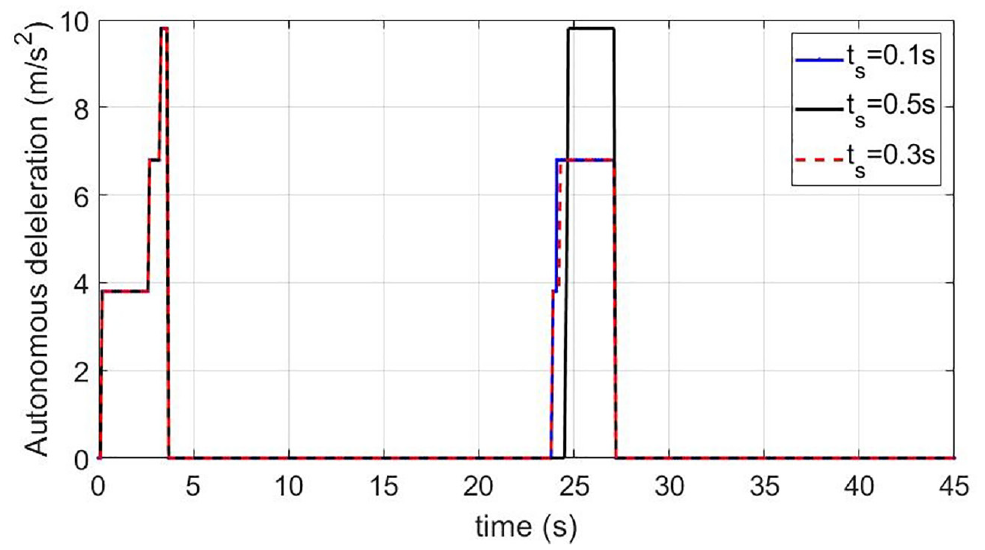
Deceleration during stop–start sequences for different sensor update time periods.
Figure 11 shows that the vehicle stops at the correct (traffic light stop line) position when the traffic light switches to red, then starts successfully again when the light switches back to green. After that, the vehicle successfully stops again safely at a CoG position 3.6 m before the crossing pedestrian and avoids a collision with the pedestrian for ts = 0.1 s and ts = 0.3 s. The distance from the front of the vehicle is 1.1 m in both cases. The same figure also shows, however, that the collision risk is not avoided with ts = 0.5 s with both x and y positions differences below 0.1 m. This is explained by the pedestrian being detected on time (around 23.5 s) when ts = 0.1 s or ts = 0.3 s, but slightly too late (approximately t = 23.8 s) with ts = 0.5 s. The vehicle automatically restarts when the pedestrian is no longer on a collision course.
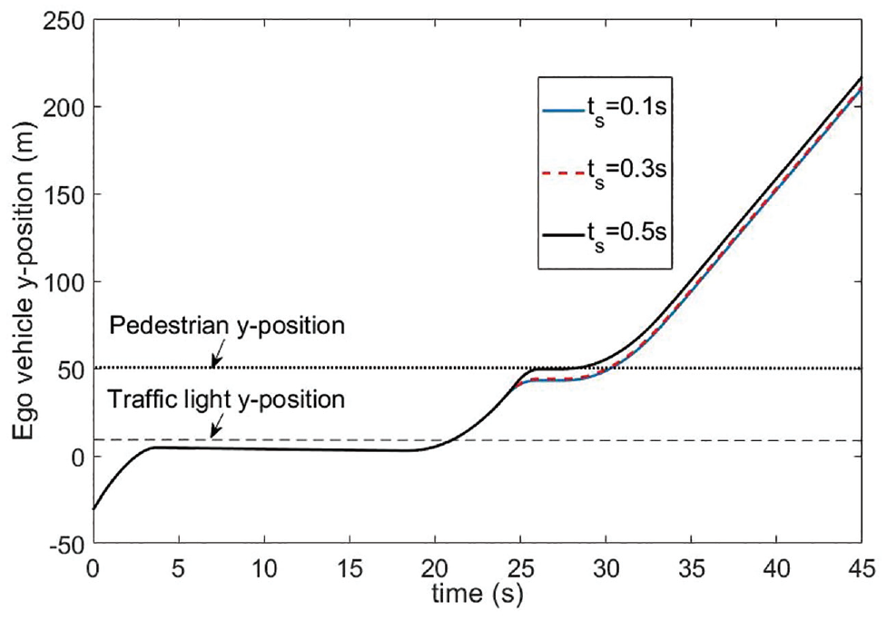
Sequence with autonomous braking for traffic light then pedestrian road user for different sensor update time periods.
Discussion on the Generality of the Proposed Approach
The proposed mode switching control approach was designed under commonly used assumptions such as zero road inclination and straight roads near traffic lights. However, the approach is systematic, provided that regions are defined at road junctions for the application of the pure pursuit controller. In simulation scenarios, the number of junctions
Conclusions
This paper has demonstrated uninterrupted, accurate, autonomous path following in a city environment using threshold-based mode switching control with steering and acceleration commands. The first control mode is applied on the main roads and uses LKA based on adaptive MPC for accurate path following at desired cruise speeds. The second mode uses a safer and more reactive pure pursuit inspired controller with waypoints at junctions including cross intersections and roundabouts to maneuver at a reduced velocity at these locations where LKA sensing is less reliable. An autonomous braking mode with a stop-start logic overrides either mode to stop and restart accurately at traffic lights or to avoid collisions with ORUs. Numerical simulations show that the switched controller meets the prescribed constraints on road curvature, acceleration, steering commands, time headway and lateral deviation. The proposed approach is systematic, provided that the speed limits are known and that road intersection areas are defined. This software development enhances the closed loop control demonstrations capabilities provided with the Automatic Driving ToolboxTM by including junctions and roundabouts and only employing LKA capabilities when it is safe.
Footnotes
Author Contributions
The authors confirm contribution to the paper as follows: study conception and design: X. Author, Y. Author; data collection: Y. Author; analysis and interpretation of results: X. Author, Y. Author, Z. Author; draft manuscript preparation: Y. Author. Z. Author. All authors reviewed the results and approved the final version of the manuscript.
Declaration of Conflicting Interests
The author(s) declared no potential conflicts of interest with respect to the research, authorship, and/or publication of this article.
Funding
The author(s) disclosed receipt of the following financial support for the research, authorship, and/or publication of this article: this work is developed with funding from Innovateuk Project Park-IT (Reference: 10509).