
Abstract
OBJECTIVE:
At the 2nd International Symposium on Bi-Digital O-Ring Testing (Tokyo Conference), I presented my trials results on the MK-I prototype reactor. In a brief synopsis of my first experiment, results demonstrated a remarkably significant variance, which matched projections, in the rate of change in muscle power for each digital (finger) used in compromising an O-Ring. This was done by selectively changing the volume of the retractor speed.
This time around, a second generation prototype retractor (MK-II) was constructed, with certain focused revisions having been made. Concentration was placed on the retractor power. In other words, the MK-II utilizes a Dial Indicator. It’s variable change allows for the proper display of the standard rate of change in the muscle power of the digital composing the ORing.
This device is composed of a retractor (MK-II), an amplifier WG1-300A, and a data recording device WR-7200. The characteristics of the MK-II is that the reactor comes to a standstill (stops) once the muscle power of the third party, whose fingers from the O-Ring, and the retractor power of the MK-II register a balanced match.
TRIAL CONDITIONS:
(1)MK-II Calibration
(2)Third-party (indirect) Bi-Digital O-Ring Test conditions
(3)Measuring electromagnetic waves within the testing environment and implementation of appropriate shielding.
The I-II digital of the third party was used to compose an O-Ring. This was compared against the O-Ring formed by the MK-II. The Dial Indicator knob was rotated slowly from 0 to 100. As the knob was rotated from 0 to 100, it was observed that the O-Ring of the MK-II began to disunite itself at the same time as that of the third party, under identical conditions of applied speed and muscle power.
RESULTS:
MK-II Dial Indicator (N=15)
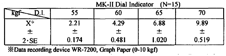
| kgf D.I. | 55 | 60 | 65 | 70 |
|---|---|---|---|---|
| X | 2.21 | 4.29 | 6.88 | 9.89 |
| ± | ± | ± | ± | ± |
| 2·SE | 0.174 | 0.481 | 1.020 | 0.519 |
Data recording device WR-7200, Graph Paper (0-10 kgf)
The O-Ring remains closed and maintains stability while the Dial Indicator is in the 55-60 scale range. In the 65-100 scale range, the O-Ring gradually opens in response to the constant traction placed on the O-Ring.
Get full access to this article
View all access options for this article.