
Abstract
The increased demand for clean renewable energy requires innovative technology designs. A dual-rotor wind turbine system is presented and modelled using Blade Element Momentum Theory. Four different rotor configurations were analysed in both structural loading and vibrational impact. A key advantage of the dual-rotor approach is its ability to maintain partial operation even if one rotor fails, a feature that could significantly increase wind farm reliability. The study explores contra-rotation as a strategy to mitigate asymmetric lateral loads, thereby reducing torsional and rolling stresses at the tower and beam locations – a critical factor for structural longevity. This investigation analysed the impact of rotor phasing, an area previously unaddressed in the literature, by focussing on system dynamics in both frequency and time domains. Our findings reveal that operating the rotors out of phase can reduce fore-aft vibrations in the connecting beam by up to 86%, without increasing overall structural loads.
Introduction
With global net zero goals, the demand for renewable energy has never been greater. Wind energy has seen constant growth and aims to be one of the largest renewable energy providers. In 2024, wind energy made up 39.1% of renewable energy in the EU, according to European Commission (2025), and this is expected to increase significantly to ensure that renewable targets are met by 2030. Scaling up wind energy production fundamentally requires increasing turbine size, a shift that brings both opportunities and challenges. While larger turbines entail higher upfront costs per unit, they benefit from economies of scale, resulting in a significantly lower cost of energy-projected to decrease by up to 35% for onshore wind by 2050 (Wiser et al., 2016). However, this scaling introduces substantial engineering obstacles, particularly as component weights and main bearing loads increase disproportionately with turbine size, demanding advanced technological solutions and innovative materials to maintain reliability and serviceability (Sieros et al., 2012). Ongoing research is driving efficiency gains by optimising aerodynamic performance and reducing structural weight through advanced composites, further enhancing the viability of large-scale wind power (Firoozi et al., 2024). Ultimately, the urgent demand for clean, renewable energy continues to drive innovation across every facet of wind turbine design and manufacturing.
Multi-rotor wind turbines (MRWTs)
Multi-rotor wind turbines (MRWTs) provide a potential route to solving many fundamental issues with upscaling wind turbines. High volumes of smaller generators and blades lend themselves to production line economies of scale, including circular economy models and increased local content. Jamieson and Branney (2012) has shown that by introducing n number of smaller rotors with an equivalent capture area to a single rotor wind turbine, the total mass of the blades decreases by a factor of
Current MRWT research
While multi-rotor wind turbine systems offer notable advantages, they also introduce new engineering challenges. Aerodynamically, studies such as Gong et al. (2023) demonstrate that blade tip vortices in multi-rotor configurations can enhance power output by up to 8.4% while accelerating wake recovery. Structurally, single-rotor turbines (SRWTs) exhibit asymmetric side-side loading due to rotor-induced aerodynamic forces, as noted by Pamososuryo et al. (2023). This imbalance generates rolling moments in the tower and torsional yawing stresses, raising durability concerns. The impact of these asymmetric loads in multi-rotor systems however remains unclear: configurations with smaller rotors could either amplify lateral forces or mitigate them through contra-rotation. Jamieson and Branney (2014) analysed large multi-rotor designs and identified extreme wind loads as the primary limiting factor, though their findings also suggested reduced fatigue damage due to lower cyclic loading ranges. Additionally, their work emphasised the increased complexity of dynamic behaviour in multi-rotor systems, noting that the proliferation of natural frequencies in such structures demands meticulous design to avoid resonant vibrations.
The non-standardisation of MRWT designs results in non-standardised degrees of freedom and so whilst eigenanalysis is an important step in turbine design, theoretical analysis becomes difficult as it is unique to each design. Filsoof et al. (2021) progressed research into modal dynamics of MRWTs by creating a methodology to extend Coleman transformations to allow calculation of natural frequencies and mode shapes in MRWTs. While prior research has demonstrated how differences in rotor height influence individual blade vibrational modes, it has not addressed the critical interplay between rotors or the cumulative effects of simultaneous excitations. This gap becomes particularly significant in multi-rotor designs where rotors operate at varying speeds. Such configurations risk exciting multiple vibrational modes concurrently – a phenomenon that could accelerate fatigue damage in structural components. All turbines are subjected to excitation from the rotor’s operational frequency (1P) and its harmonic components. Three-bladed wind turbines are also subjected to blade-passing excitation (3P) and its associated harmonic components. The 3P excitations are particularly relevant due to the lower frequency which can interact with the turbine structural dynamics. As shown by Han and Leithead (2014), 1P excitations primarily drive blade bending moments, while 3P frequencies dominate hub and drivetrain loading. In multi-rotor systems, however, the superposition of these frequencies across multiple rotors, especially at non-synchronised speeds, creates complex vibrational interactions that remain poorly understood. These dynamics could amplify stress cycles in critical components, potentially undermining the fatigue life improvements promised by distributed rotor architectures.
Research gap and aim
This study addresses the analysis of a dual-rotor wind turbine as a foundational step toward understanding more complex multi-rotor systems. By employing a simple monopile tower with a horizontal connecting beam and coplanar rotors mounted at each end, the research isolates the effects of rotor interaction. Although not intended as an optimal design, this configuration enables a clear assessment of load distribution, frequency coupling and the potential of contra-rotation as a strategy to reduce asymmetric loading in dual systems, which has been vaguely studied according to authors’ knowledge. Figure 1 highlights this coplanar dual-rotor design created using HAWC2’s accompanying animation software. The insights gained from this dual-rotor analysis provide an essential initial framework for evaluating the structural and vibrational challenges that will arise as the number of rotors increases in future wind turbine designs. Image of coplanar dual-rotor structure and global axes, created for the purpose of reader clarity and not used in analysis.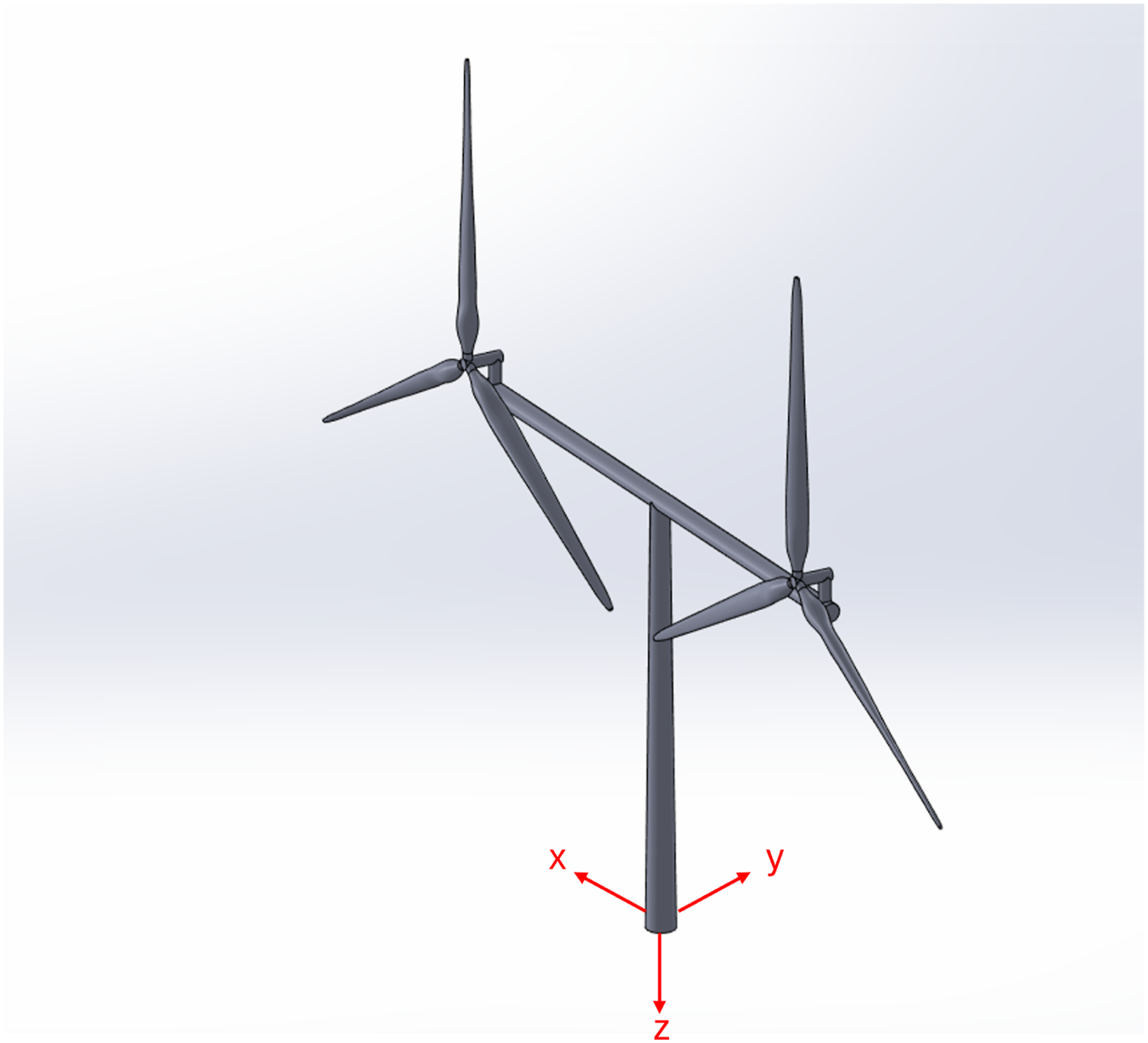
Model parameters and methodology
Blade element momentum theory (BEMT)
Blade element momentum theory (BEMT) has been used extensively to assess wind turbine performance (Duan and Zhao, 2010; Mahmuddin, 2017; Tahir et al., 2019). BEMT provides a computationally efficient framework for wind turbine aerodynamic analysis by balancing iterative solutions with empirical corrections, avoiding the prohibitive computational costs of high-fidelity methods like computational fluid dynamics (CFD). For this study, the Horizontal Axis Wind turbine Code 2nd generation (HAWC2) (HAWC2: An Aeroelastic Code, 2025) which utilises BEMT was selected due to its time-domain aeroelastic modelling capabilities and modular architecture, which enable detailed simulations of complex rotor–structure interactions while maintaining computational tractability. Unlike conventional BEMT implementations that iteratively solve for axial (a) and tangential (a′) induction factors, HAWC2 employs a unique approach: it first calculates thrust (C
T
) and torque (C
Q
) coefficients at each blade element using aerofoil polars and then derives induction factors directly via a third-order polynomial approximation (equation (1)). This method avoids convergence issues associated with traditional iterative schemes, enhancing stability in dynamic simulations of rotor-tower coupling or fault conditions.


The Prandtl tip correction factor, F, is introduced to correct the BEMT assumption that there is an infinite number of blades. In HAWC2, this is unchanged from the modification made by Glauert (1935) and can be seen in equation (3). This is then applied to equation (1) by replacing C
T
by C
T
/F.

The aerodynamic loading is then computed and compared to the structural loading which is dependent on structural properties such as geometry and deflection. If the aerodynamic and structural loads are not balanced, then structural properties are updated and iterated until convergence is reached. The multi-body formulation allows complex designs, such as MRWTs, to be modelled. To explore any differences between the methods used, the initial outcomes from HAWC2 were compared to another relevant open access software that solves the BEMT equations using a traditional approach, Qblade (Marten et al., 2013).
Rotor design
The rotor design for this study was based on the validated NREL 5MW reference turbine (JM et al., 2009). To adapt this concept for MRWT applications, the system was downscaled to a 250 kW configuration aligned with existing modular wind energy systems (Myriad Wind Energy Systems, 2024). A linear reduction scale factor (RSF, equation (4)) governed the geometric scaling of blade length (13 m) and hub dimensions to preserve structural proportionality. However, rotor aerodynamics exhibit non-linear scaling behaviours due to Reynolds number effecting lift-to-drag ratio variations (Canet et al., 2021). Consequently, chord lengths underwent iterative adjustments in QBlade to maintain target power coefficients while compensating for these aerodynamic discontinuities. QBlade was employed due to its rapid parametric analysis capabilities, enabling efficient comparison of BEMT results with HAWC2 simulations. This cross-validation ensured consistency in load predictions despite differences in each tool’s induction factor calculation methods (Madsen et al., 2020).

For the chord length, the RSF seen in equation (4) was not suitable as it resulted in very poor performance from the rotor. As such, the RSF for chord length was iterated until a value of 0.13 was found to be adequate and resulted in a 266.3 kW rated power. The blade length remained scaled using the RSF seen in equation (4). This overcompensation of rated power both accommodated for the imperfect efficiency of the NREL generator as well as the new change in Reynolds number which was still to be accounted for. The 5 MW NREL rotor operates at a Reynolds number of 6 to 7 million, which is magnitudes larger than the newly scaled rotor (JM et al., 2009). The aerofoil lift, drag and moment coefficient data used in the NREL report was primarily sourced from the Dutch Offshore Wind Energy Converter (DOWEC) (Kooijman et al., 2003) study from which the 61.5 m rotor is based. In neither the DOWEC study (Kooijman et al., 2003) nor the NREL report (JM et al., 2009), the methodology for which the Reynolds number was calculated was mentioned. As such in this paper, the Reynolds number was calculated at 75% chord length based on the studies done by Allsop et al. (2016, 2017), resulting in a Reynolds number of 1.699E5. Further iteration was possible with newly found rated windspeed; however, this only affected the Reynolds number slightly, which had a negligible impact on calculated lift, drag and moment coefficients, C L , C D and C m , respectively. With the new Reynolds number, XFoil simulations were run on each aerofoil for a range of angles of attack. QBlade has built-in XFoil capabilities and so this was initially carried out within the software. Following the methodology from the NREL report (JM et al., 2009), the 2D aerofoil data was corrected for 3D performance, as well as extrapolated over the full −180 to 180deg angles of attack necessary for the BEMT software. This involved correcting for rotational stall delay using Selig and Eggers method, Viterna method to extrapolate coefficients beyond stalling angles of attack and finally incorporating dynamic stall. This is primarily to accommodate the effect of rotation on the boundary layer as well as stall-delay. The stall-delay effect is particularly important as it can result in high-cycle fatigue loads which are highly relevant in blade and rotor design (Dumitrescu and Cardos, 2011).
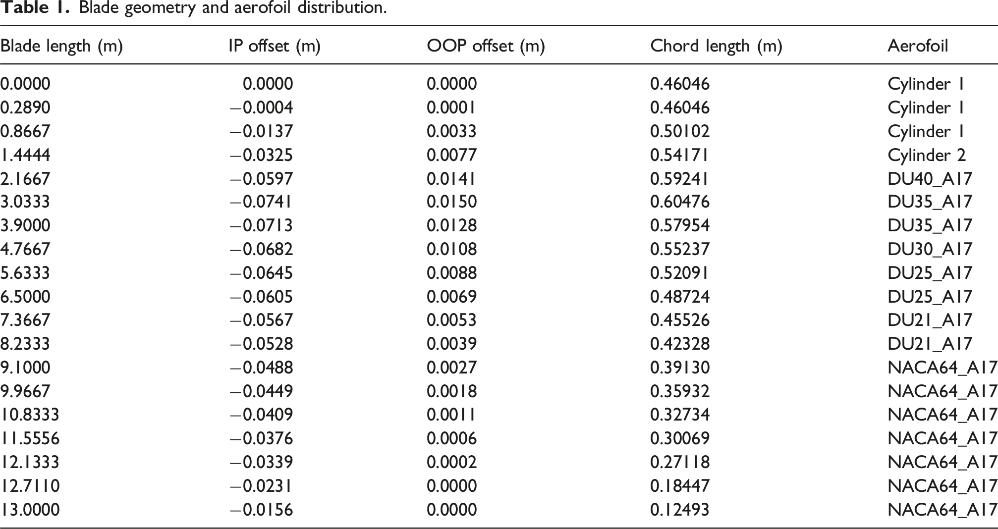
The resulting 3D aerofoil data was then compared with 3D aerofoil data calculated using the AirfoilPrep v2.0 worksheet created by Hansen (2024) and was deemed similar enough to verify the calculated lift, drag and moment coefficients for each aerofoil. Figure 2 shows the C
D
and C
L
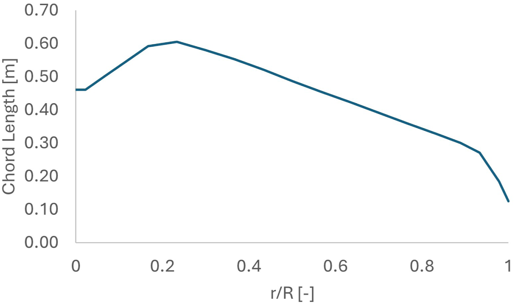
of the DU25_A17 aerofoil as a function of angle of attack as calculated by QBlade and by the AirfoilPrep v2.0 worksheet (Hansen, 2024). The remaining aerofoils and their associated properties are not shown for simplicity, but the outcomes followed the same trend when comparisons were made. The twist of the blade remained unchanged from the NREL 5MW blade. Table 1 shows the new scaled blade lengths and their associated aerofoils, with the chord shape and aerodynamic properties in between each section being interpolated. The in plane (IP) and out of plane (OOP) offset of the blade centreline are also shown in Table 1, both of which are used in HAWC2 and shown for completeness of the blade design. Figure 3 shows the chord length against the non-dimensional blade length. Graph of C
D
(solid lines) and C
L
(dashed lines) as they vary with angle of attack for the DU25_A17 Aerofoil. Blade geometry and aerofoil distribution. Graph of chord length of the blade as it varies with non-dimensional blade radius r/R.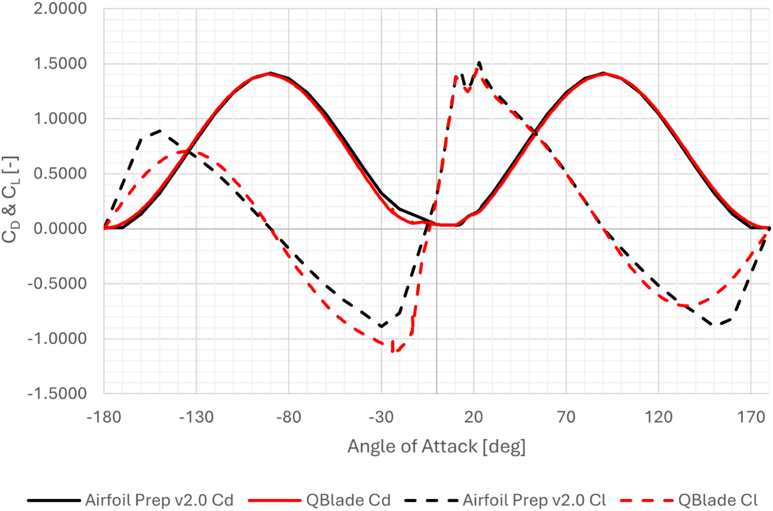
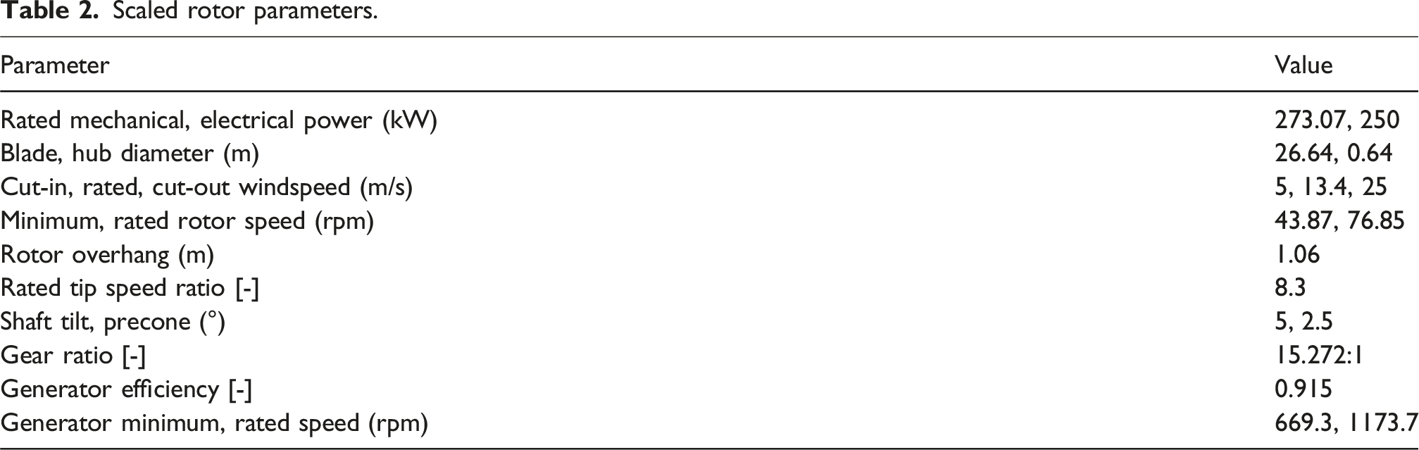
Scaled rotor parameters.
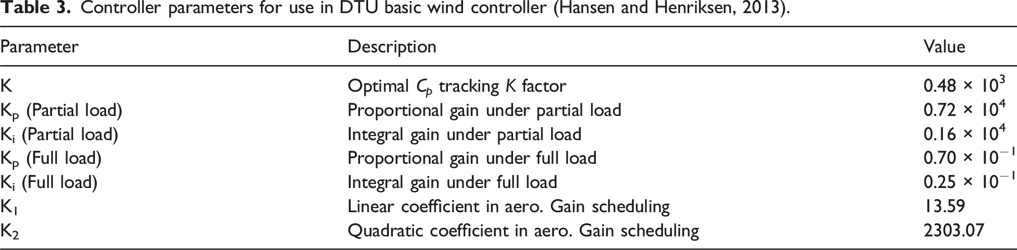
Controller parameters for use in DTU basic wind controller (Hansen and Henriksen, 2013).
Rotor verification
To verify correct rotor implementation, key aerodynamic parameters – including thrust, torque, rotor speed and blade pitch angle – were compared between the QBlade and HAWC2 models across a range of wind speeds. Ensuring that both BEMT software tools produced consistent aerodynamic loading was essential, as this underpins the accuracy of subsequent structural loading predictions. This validation is particularly important for time-domain analyses, which depend on precise load histories to assess extreme loading events, as well as for frequency-domain studies that focus on rotor operating frequency excitations and their harmonics. As shown in Figure 4, the steady-state results from HAWC2 (solid lines) and QBlade (dashed lines) demonstrate nearly identical rotor speeds and very similar pitch angles across all wind speeds. Consequently, the calculated power, thrust and torque are also consistent between the two models, confirming that the aerodynamic loading is accurate and providing a reliable foundation for further structural and vibrational analysis. Steady-state responses as a function of windspeed as calculated by HAWC2 and QBlade.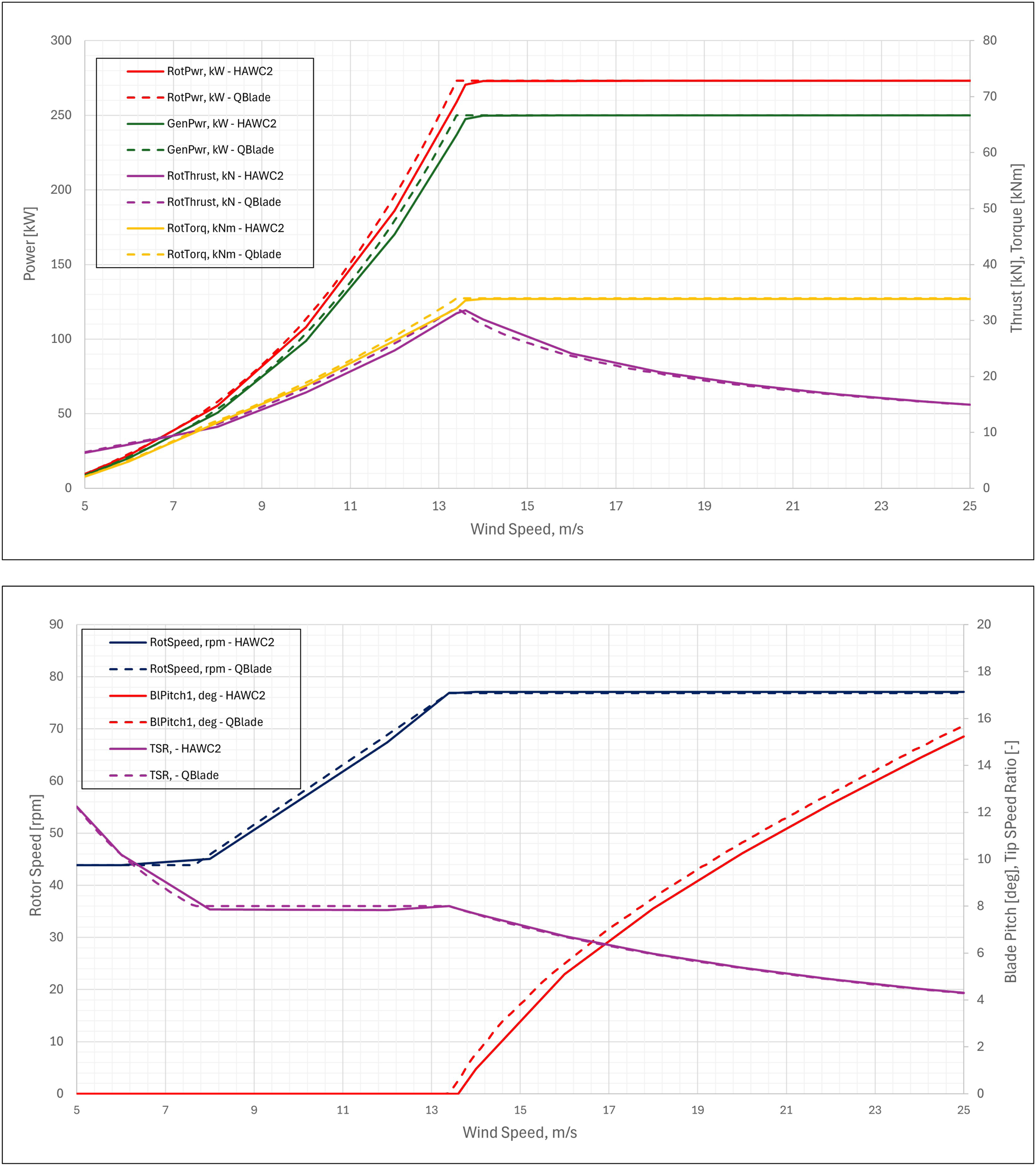
HAWC2 model
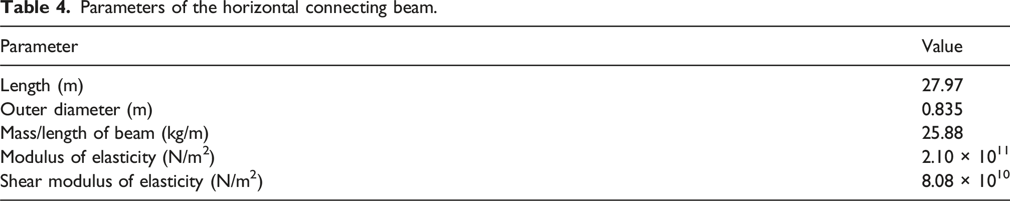
The HAWC2 model was constructed using a simplified dual-rotor architecture comprising a scaled-down NREL 5MW tower and a uniform horizontal connecting beam. The tower geometry, reduced using the linear Reduction Scale Factor (RSF, equation (4)), resulted in a 19 m tall, tapered structure. A uniform beam with a circular cross-section matching the tower’s top diameter was included horizontally to support the rotors. A key limitation of BEMT tools like HAWC2 is their inability to model blade-tip aerodynamic interactions between co-planar rotors. While studies such as Gong et al. (2023) and Ghaisas et al. (2020) demonstrate that tip interactions can enhance power output by up to 8.4% at optimal spacings (0.4 rotor diameters, D), this effect was intentionally minimised by spacing rotors 0.05D apart due to having negligible performance impact (Jamieson and Branney, 2014). The resulting beam length of 27.97 m ensured this spacing while maintaining structural simplicity. To isolate rotor interaction effects, aerodynamic drag on the beam itself was excluded from simulations. Figure 5 illustrates the final assembly, with the global x- (lateral) and z- (vertical) axes annotated; the y-axis aligns with the turbine’s fore-aft direction. Additionally, relevant moments and forces which are later discussed have been annotated. Critical beam dimensions, including cross-sectional properties and material specifications, are detailed in Table 4. Image of dual-rotor structure with x- and z-axes included. Relevant moments, M
y
and M
z
, and forces, F
z
, are annotated for reference. The y-axis points away from the reader. Parameters of the horizontal connecting beam.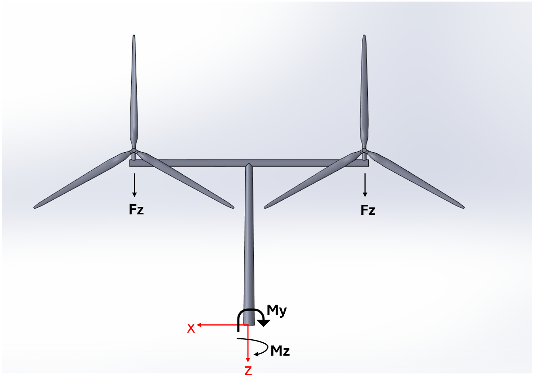
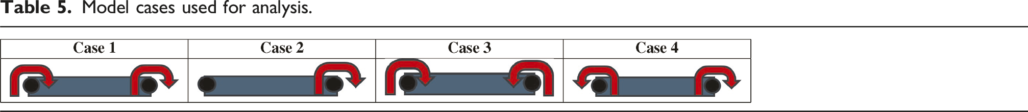
Model cases used for analysis.

Time-domain analysis
Each case was then analysed in the time domain across various windspeeds in the operating range. As the focus of this work was to analyse the interactions between the rotors and how this affected the connecting beam, wind conditions were selected that only varied with height using the power law and a power coefficient of 0.2, as per IEC standards (Nielsen et al., 2009). HAWC2 allows the forces and moments vectors to be interpolated at any point in a body and so this was used to analyse specific points on the beam, particularly the centre and at the extremes, and the base tower. These locations are important as they are high stress locations and likely vulnerable to high vibrations. A standardised global coordinate system was used to provide consistency in the results, as seen again in Figure 5.
Frequency-domain analysis
Vibrational analysis was undertaken by first collecting time-domain acceleration data at predefined intervals along the horizontal beam under steady-state wind conditions. Initial non-stationary data was deleted prior to analysis. Post-processing in MATLAB employed Welch’s averaged periodogram method, implemented via the pwelch function, to estimate power spectral density (PSD). This approach divides the time-series data into overlapping segments, computes the Discrete Fourier Transform (DFT, equation (5)) for each segment and averages the resulting periodograms to reduce spectral noise (Same et al., 2021).
The values are then squared, and an average is taken across the various sections which provides an estimation of the PSD. This can be seen in equation (6) and is again shown by Same et al. (2021).
Several variables can affect the final output in this analysis, such as sampling frequency, fs, the section overlap and the window size/type that is used on each section. For this analysis, the sampling frequency was determined by the HAWC2 model as the measurements were taken at a specific frequency of 50 Hz. It was necessary to ensure the Nyquist frequency, which is half the sampling frequency (Austerlitz, 2003), was larger than the 1P and 3P frequencies that were analysed. A 50% overlap was used on each window to reduce the effect of tapering that occurs at the edges of the data when using an Hanning window type (Braun, 2001). PSD graphs also tend to use a logarithmic scale on the y-axis with units dB/Hz. For this paper, it was more instructive to look at the amplitude of the vibrations that were occurring and as such an Amplitude Spectral Density (ASD) was used. This can be found by taking the square root of the PSD vector seen in equation (7).
As mentioned, the acceleration was measured at intervals along the horizontal beam when a windspeed of 25 m/s was applied, and an ASD graph was created for each interval along the beam. As this is the cut-out windspeed, the rotors were operating at constant rated speed and thus should not interact with the natural frequencies of the system. As the scope of this study was to analyse the vibrational impact of side-by-side rotors in general to allow comparisons to other MRWT designs, these resonance points were not investigated as these are unique to the specific turbine and structure design. In this frequency-domain section, the blade passing frequency, 3P, and its various harmonics were explored.
Results and discussion
Time-domain analysis
Figure 6 shows the magnitude of vertical reaction force experienced by the beam, F
z
, at rated windspeed, along the non-dimensional length of the beam (l/L). Case 1, Case 3 and Case 4 are completely symmetrical, and Case 3 and Case 4 have identical F
z
. Case 3 and Case 4, however, are consistently 5% larger than Case 1. Case 2 is not symmetrical in its loading and is 10–12% less than Case 1 on the non-operational side and 1% less on the operational side. As expected, the vertical loading is a function of the aerodynamic loading. Case 2 also highlights that when one rotor is non-operational, there is not a large change in vertical loading. Thus, aerodynamic loading induced by the rotor during operation is minimal in comparison to loading induced by the weight of the RNA. Magnitude of shear force in vertical direction, F
z
as a function of non-dimensional length of the beam l/L, with broken y-axis.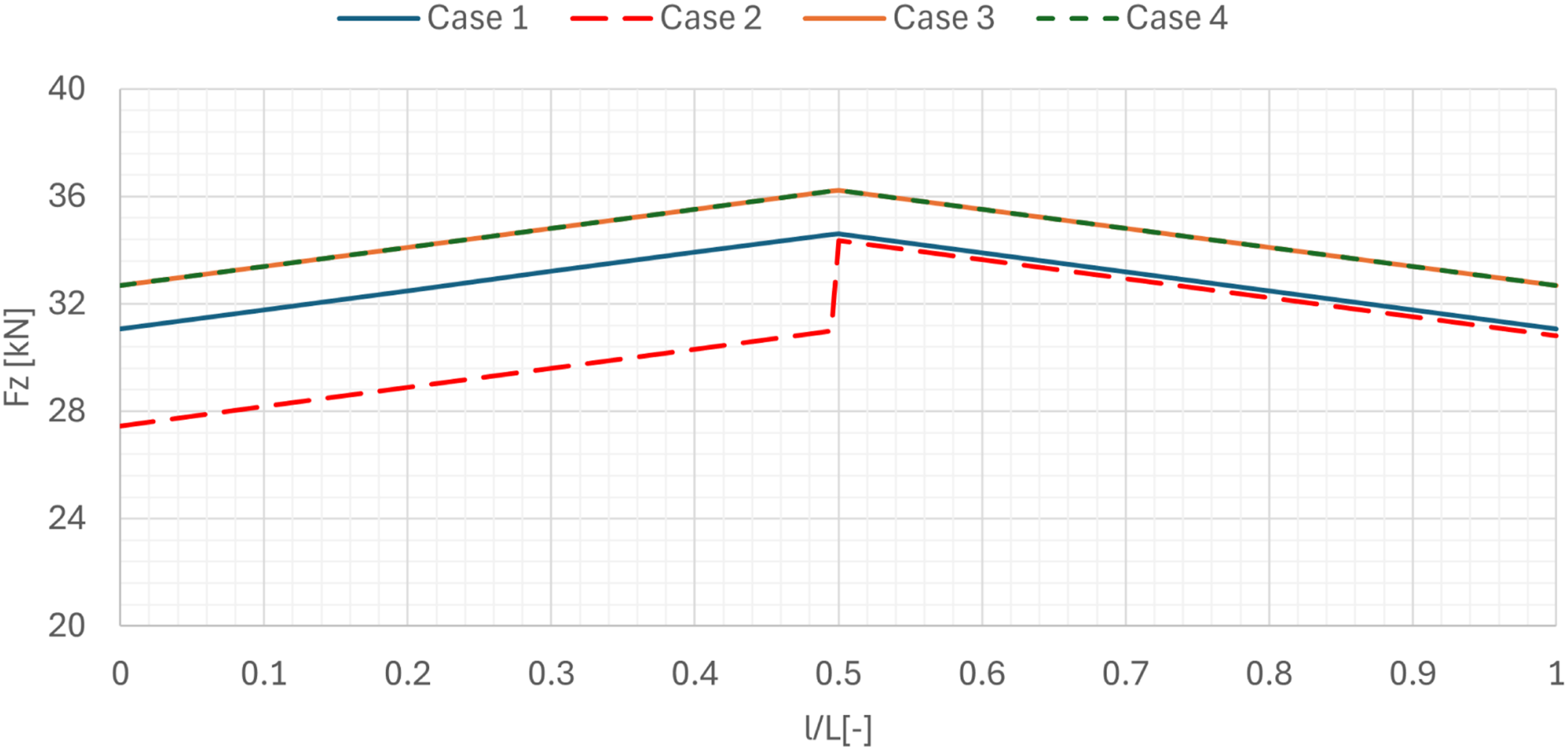
The deflections of the main beam are seen in Figure 7. Despite Case 1 being symmetric in loading, the vertical deflections are not. The deflections seen in Case 2 are within 1% of Case 1 at the operational side and show a 5% decrease at the non-operational side. Inversely, Case 3 and Case 4 have an identical deflection at either side of the beam. This is likely due to the lateral loading induced by rotors. Vertical deflection of horizontal beam at 0l/L and 1l/L at rated windspeed.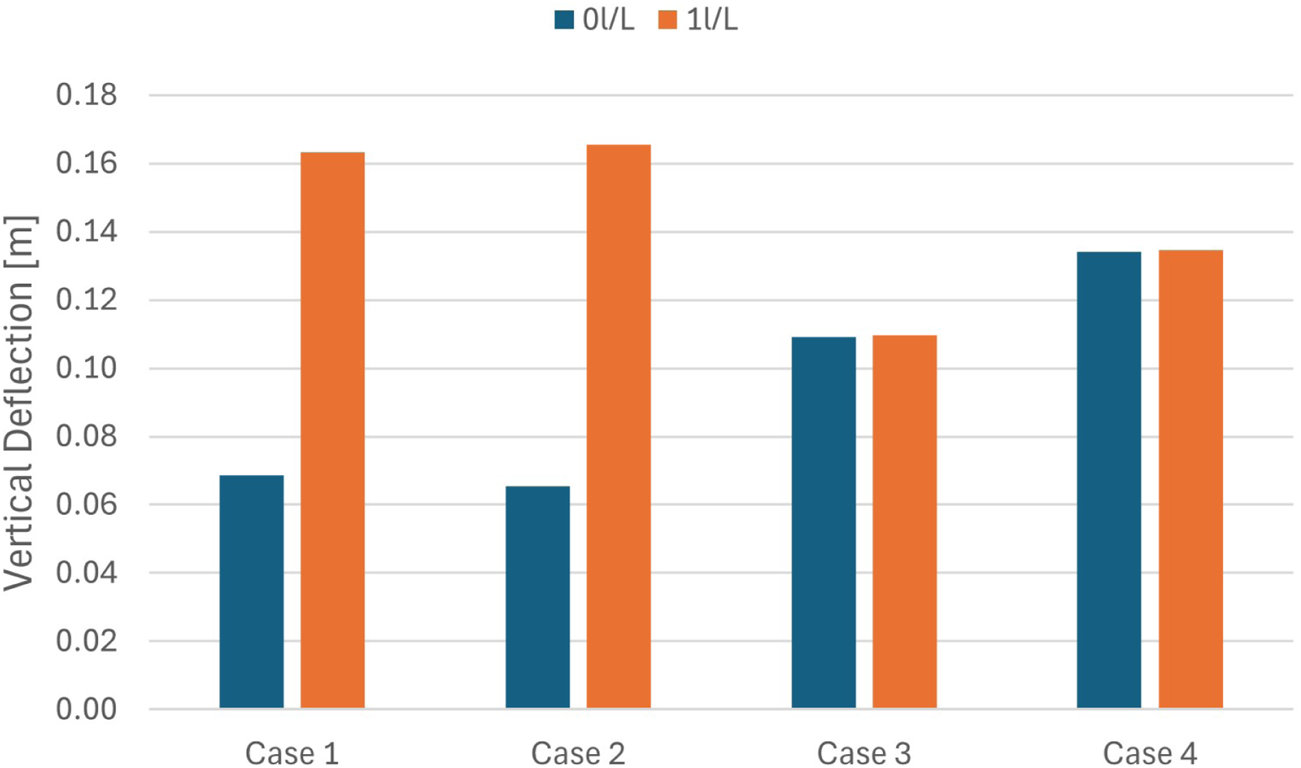
In Case 1, both rotors operate co-rotationally (clockwise), generating lateral loads aligned in the same direction. These dynamic forces superimpose onto the static deflection induced by the rotor-nacelle assembly (RNA) weight, resulting in asymmetric vertical displacements: the right-hand rotor displaces toward the tower due to accumulative loading, while the left-hand rotor deflects outward. Case 2 exhibits similar asymmetric deflection patterns, but with lateral loading contributed by only one operational rotor, reducing the net lateral force magnitude while preserving the directionality of displacement. In contrast, Cases 3 and 4 employ contra-rotating rotors (clockwise/counterclockwise pairing). Here, opposing lateral loads generate symmetric compressive or tensile forces across the connecting beam. This cancels asymmetric bending moments, producing a symmetric vertical deflection profile centred on the tower axis. The contra-rotational configuration effectively decouples lateral aerodynamic forces from static RNA-induced deflections, mitigating cumulative displacement extremes observed in previous cases.
The phase difference between the rotors was also varied by changing the initial azimuthal position of the left rotor such that it led the right rotor. This had negligible effect on the loading in either the horizontal beam or the tower and thus does not pose a design concern with regards to ultimate loading.
Figure 8 describes the rolling moment about the y-axis, M
y
, at the base of the tower. This highlights how the aerodynamic loading interacts with the tower at its most significant location. When comparing Case 1 and Case 2, when one rotor is not operational, the rolling moment is significantly reduced. At low windspeeds, this is not the case, but this only applies between 5 and 8 m/s where the aerodynamic loading is much lower. As the windspeed increases, the loading in Case 1 increases steadily from 7% larger to 21% larger. The increase is steeper before rated windspeed but still does increase after. It can thus be said that the additional rotor has a summative effect on the base rolling moment. When comparing the contra-rotating cases, it can be seen in Figure 8 that the rolling moment cancels out. In both Case 3 and Case 4, the moment is less than 1 kN across all windspeeds, which highlights a balancing effect when the rotors act in opposite directions. This is likely due to the symmetrical lateral loading mentioned above, which results in net zero lateral loading at the centre of the beam and thus no rolling moments about the base. Steady-state rolling moments, M
y
, at the tower base as a function of windspeed.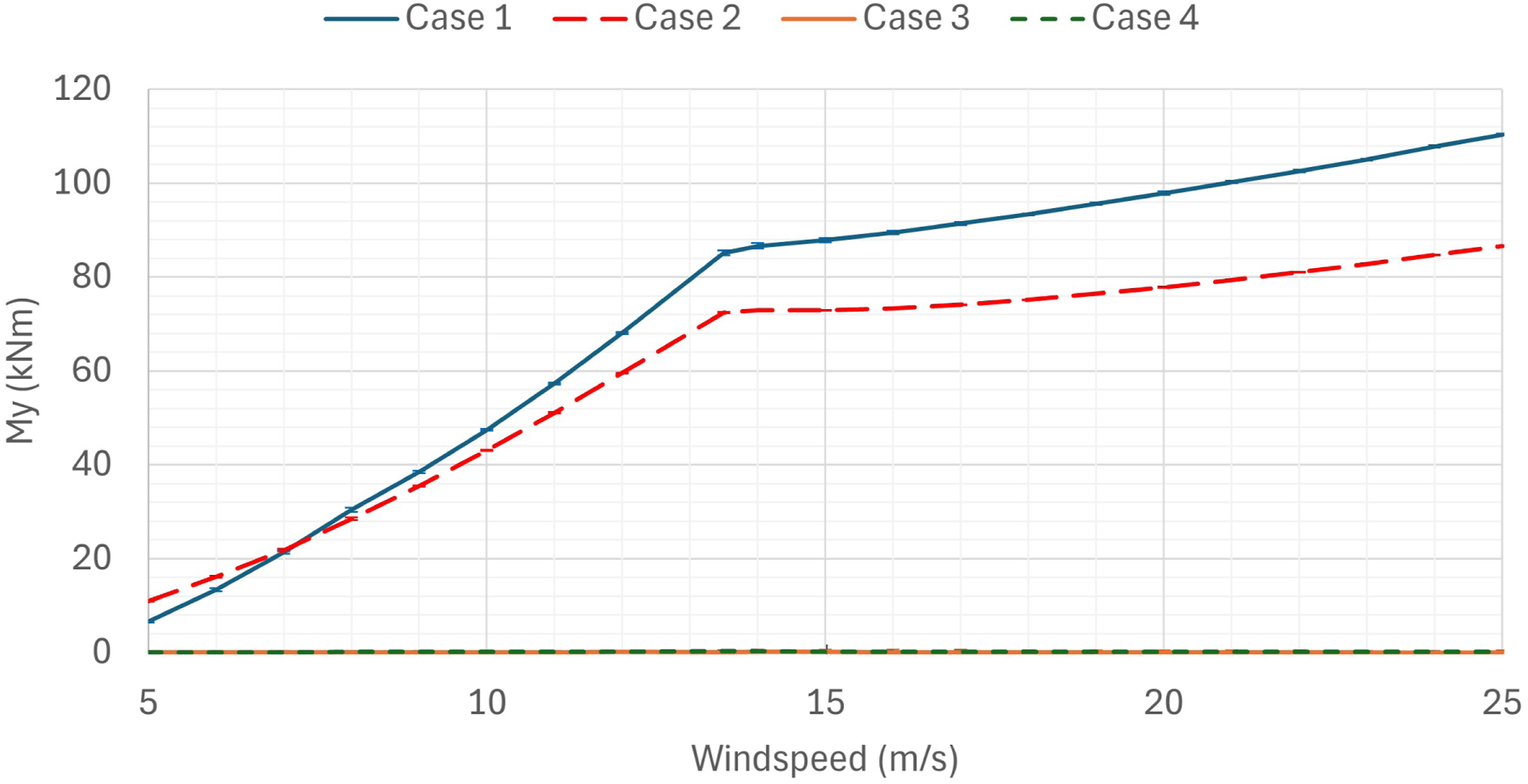
Similarly, from Figure 9, there is a yawing moment, M
z
, about the tower base in Case 1, like seen in a single rotor wind turbine as shown by Makarios et al. (2016). When the rotors are contra-rotating as in Case 3 and 4, this torsional moment is reduced to zero. This again highlights the ability of the contra-rotating cases to reduce asymmetrical loading on the tower, which has resulted in failure of wind turbines in the past (Makarios et al., 2016). It is likely that this M
z
seen in Case 1 is a result of the lateral force in the horizontal beam. This is because the rotors are offset from the tower, so as not to hit the tower, and thus F
x
is acting aft centre and create a yawing moment about the tower. Steady-state yawing moments, M
z
, at the tower base as a function of windspeed.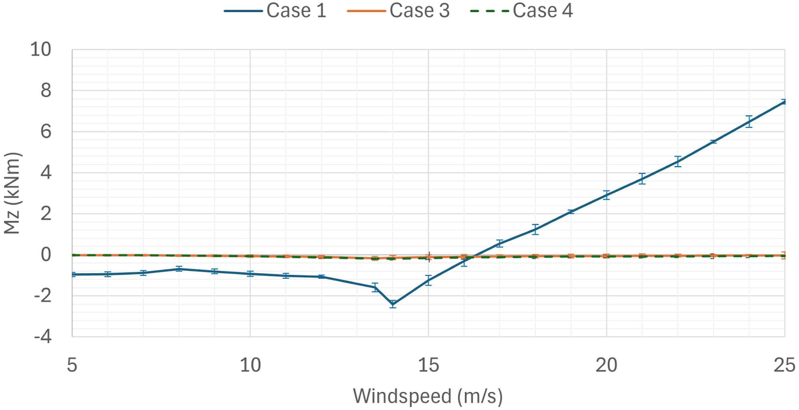
Case 2 was not included in Figure 9 as the moments were two orders of magnitude larger than all other cases. This is inherent to the design of the structure, as opposed to the interaction between the rotors. This is due to the thrust force of the operational rotor being the dominant rotating force and since this is asymmetrical due to the partial operation, the yawing moment is thus much larger, with a maximum of 436kNm at rated windspeed. This finding is significant if the design of the multi-rotor wind turbine has an even number of rotors distributed equally on either side of a supporting tower, as one of the main benefits described is the ability to operate when one rotor is not operational. Any symmetrical design will thus create asymmetrical loading and large torsional moments about the base of the tower which can lead to failure much sooner than if fully operational. As such, this is a major operation consideration, with one rotor failing requiring immediate action to balance the thrust forces and reduce the risk of failure. This situation may also arise when spatial or temporal variations in wind speed generate significant asymmetrical thrust loads acting aft of the central tower. Consequently, from a design standpoint, configurations employing a larger number of smaller rotors may be preferred, as this reduces the thrust contribution of each individual rotor and thereby lowers the likelihood that the failure of a single rotor will induce substantial yawing moments at the base. Alternatively, designs without a central tower and a more distributed support structure like that of Wind Catching Systems (Wind Catching Systems, 2025) may be more favourable.
Frequency-domain analysis
After measuring the acceleration at specific nodes along the connecting beam and plotting the ASD, it was clear that the 3P frequency was the largest contribution to vibration, as seen in Figure 10. This is as expected as 3P excitations tend to be dominant in structural vibration as shown by Han and Leithead (2014). Comparing the amplitudes between the x-, y-, and z-directions, vibration in the y-axis had the largest amplitude by two orders of magnitude and corresponds to the fore aft vibration. ASD graph of acceleration measured at the centre of the horizontal beam and 3P frequency highlighted in red circle.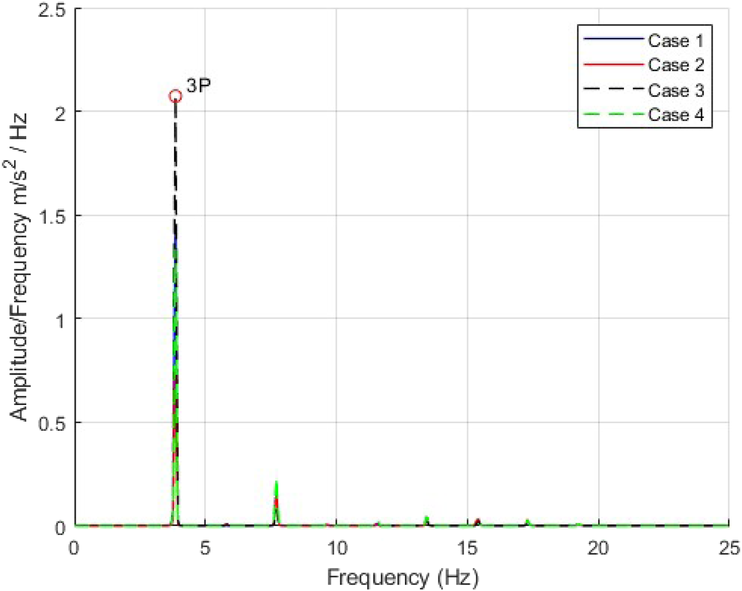
Figure 11 shows this maximum amplitude at the 3P frequency as a function of l/L when both rotors are completely in phase, where l is the length along the beam being measured and L is the full length of the horizontal beam from rotor to rotor. This highlights how vibrations propagate along the length of the beam as a result of the 3P excitation. Case 1 and Case 2 are both inherently asymmetrical and, as a result, have larger vibrations at 1l/L, the operational side in Case 2. However, Case 3 and Case 4 both have vibrations within 3% when comparing 0l/L to 1l/L, as a result of the inherent symmetry. All cases appear to peak in the centre of the beam at the location of the vertical support, 0.5 l/L, even when only one side of the beam is excited in Case 2. Case 3 has the largest vibrations, 120% larger than Case 1 at 0.5 l/L. This is possibly due to the way the side-side vibrations act to compress the beam and bend it outwards; however, it is not entirely clear as Case 4 only has a 15% increase compared to Case 1. Case 2 however sees a 36% decrease in vibration at 0.5 l/L when compared to Case 1 and as such there must be some negative interaction between the rotors that amplifies the vibration at the centre of the beam. As phasing of the rotors has not been varied however, it is not clear if these are the maximum amplitudes of vibration and so variations in phasing were further investigated. Amplitude measured at 3P frequency as a function of the non-dimensional length of the beam l/L.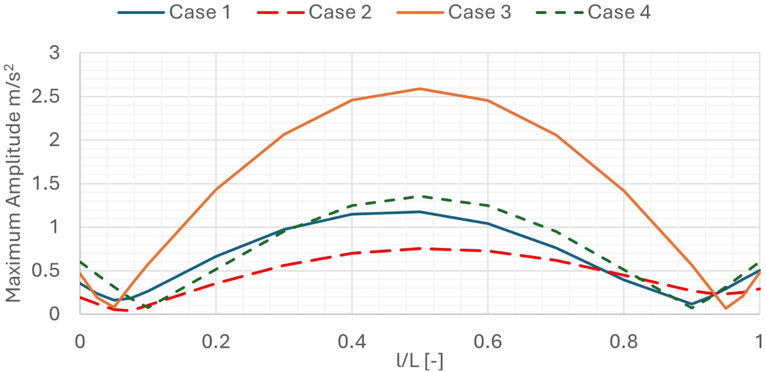
An investigation on phase difference was then conducted by varying the initial azimuthal position of the left rotor at 0 l/L. After varying the initial position by 10 deg, the maximum amplitude at the 3P frequency was measured at 0.5 l/L as this was identified as the location with the largest amplitudes. Figure 12 shows this amplitude as a function of phase difference. It can be seen that in both Case 3 and Case 4, the results are symmetrical in that the maximum amplitude occurs when the rotors are completely in phase, at 0 and 120 deg, and the minimum when the rotors are completely out of phase, at 60 deg. Yet, with Case 1, the asymmetry results in a maximum amplitude when the left rotor leads the right by 90 deg and a minimum amplitude when the left rotor leads by 30 deg. As expected, in all cases, when the left rotor leads by 120 deg, the rotors are again completely in phase and thus have the same amplitude of vibration at 0 deg. The phasing of rotors clearly plays a large role in the fore-aft vibration with both Case 3 and Case 4 seeing an 86% and 85% drop in amplitude, respectively, when one rotor leads the other by 60 deg. Similarly, Case 1 sees an 83% drop when the left rotor leads by 30 deg when compared to the left rotor leading by 90 deg (minimum and maximum amplitudes, respectively). The comparisons between Cases 1, 3 and 4 made from Figure 11 were when the rotors were completely in phase, and as such was not the maximum amplitude for Case 1. Thus, direct comparisons can now be made to accurately evaluate the Case for which the maximum amplitude of vibration occurred. The maximum amplitude of Case 3 is instead only 57% larger than Case 1 and is 18% less in Case 4. The minimum amplitude of Case 1, Case 3 and Case 4 is also 63%, 53% and 73% less than Case 2, respectively, which highlights that there is a cancellation vibration effect within these MRWT designs. Maximum amplitude of vibration measured in the centre of the horizontal beam (0.5 l/L) in the fore aft direction, as a function of phase difference in the rotors.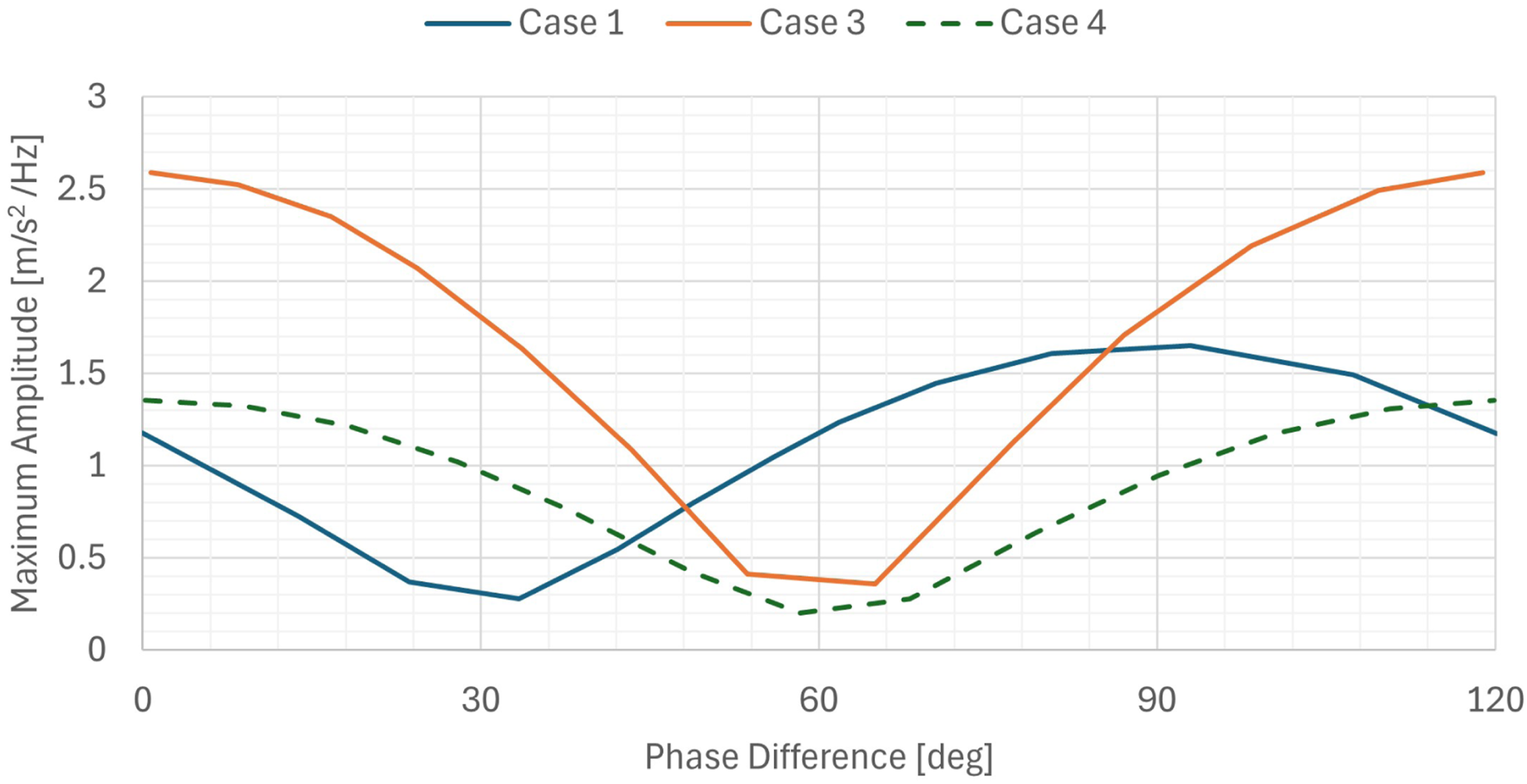
Because research on multi-rotor wind turbines remains limited, the mechanisms by which rotor phasing amplifies vibration are not yet fully established. However, rotor–rotor interactions have been examined in other contexts. Xu et al. (2024) discuss these interactions in detail, focussing on global rotor noise, and analysed the sinusoidal character of rotor thrust and how rotor phasing can lead to superposition of these thrust forces. By analogy, the same mechanism is expected to apply to the dual co-planar wind turbine system considered in this study, where superposition of thrust forces under in-phase operation produces larger excitation forces and, consequently, larger vibration amplitudes.
This investigation highlights the potential to implement control strategies that monitor rotor azimuthal positions and actively manage phasing to minimise vibrations. However, achieving precise phase control may be challenging in practice – especially under turbulent wind conditions – that could adversely impact overall performance. Therefore, a more practical approach may be to design the system to withstand worst-case phasing scenarios, ensuring structural integrity and reliability even when optimal phasing cannot be maintained.
Conclusion and future work
This paper aimed to target the gap in multi-rotor research involving rotor interactions and their effect on the support structure. This is vital for the implementation of multi-rotor turbine systems as the static and dynamic loading implications are a major design consideration. By analysing the dual-rotor structure in both the time and frequency domain for various rotor configurations, the structural loading and vibrational impact of multiple rotors was highlighted. Four cases were introduced; one in which both rotors were operating in the clockwise direction, one in which the left rotor was non-operational, and two cases with contra-rotating rotors spinning in opposite directions. The main conclusions drawn from these analyses were as follows:
Time-domain analysis
Vertical loading is reduced by 10–12% when one rotor is non-operational and does not affect loading on the operational side. Lateral loading induced by the rotors is summative with the vertical loading and results in asymmetric deflections in Case 1 and Case 2. Contra-rotation allowed net zero lateral loading at the centre of the beam which reduced rolling and yawing moments at the base of the tower to zero. Yawing moments in Case 2 were obtained at the tower base with two orders of magnitude larger than the other cases as a result of asymmetric thrust forces.
Frequency-domain analysis
The largest vibrations were obtained at the 3P frequency located in the fore-and-aft direction, at the centre of the horizontal support beam. The phase of the rotors played a large role in the magnitude of the vibration, with a reduction of up to 86% in amplitude of vibration when out of phase. In both counter-rotating cases, maximum vibration levels occurred when the rotors were perfectly in phase, while minimum vibrations were observed when the rotors were completely out of phase. The largest vibration in Case 1 was obtained when the left rotor led the right by 90deg and its lowest when the left rotor led by 30deg. The first inwards contra-rotating case saw a 58% increase in amplitude of vibration, yet the second outwards contra-rotating case saw an 18% decrease compared to Case 1.
The key finding from this section is the significant influence of rotor phasing on vibration magnitude in multi-rotor wind turbine (MRWT) systems. Notably, the highest vibration amplitudes did not always correspond to in-phase operation; only outward contra-rotation consistently reduced vibration levels. These results demonstrate that both constructive and destructive vibrational interactions can occur between rotors, with significant implications for a broad range of MRWT configurations, an interaction that had not been previously addressed in the literature. Whilst both counter-rotating cases allowed negligible torsional and rolling moments at the base of the tower, due to the results pertaining to vibration in the beam, the inwards counter-rotating design is not recommended as a design option.
Future work
Future research should explore advanced control strategies to minimise phase differences that amplify vibrations, as this paper has highlighted the importance of rotor phasing on the resulting fore aft vibrations. Additionally, extending this analysis to a wider range of operating conditions would help identify resonance phenomena and further clarify the role of rotor phasing in vibration mitigation. The introduction of more complex designs relative to SRWT designs leads to a much larger number of relevant natural frequencies as highlighted by Jamieson and Branney (2014), and so the significance of phasing on resonance is an important area of study.
Footnotes
Acknowledgements
A. Winning would like to thank the HAWC2 support team at Danish Technical University for their prompt and insightful guidance with the software.
Author contributions
A. Winning and S. Ordonez-Sanchez conceived of the presented idea. A. Winning conducted the modelling and analysis under supervision of S. Ordonez-Sanchez. L. Camacho verified the application of the control systems used. A. Winning and S. Ordonez Sanchez discussed the results and contributed to the final manuscript. L. Camacho reviewed the manuscript.
Funding
The authors received no financial support for the research, authorship, and/or publication of this article.
Declaration of conflicting interests
The authors declared no potential conflicts of interest with respect to the research, authorship, and/or publication of this article.
Data Availability Statement
Copyright
Copyright ⓒ 2025 SAGE Publications Ltd, 1 Oliver’s Yard, 55 City Road, London, EC1Y 1SP, UK. All rights reserved.