
Abstract
The wind energy generation system is complex because of varying wind speeds and its control systems to improve its ability of energy harvesting. This paper considers a hydraulic actuator-based variable-pitch angle control of a 1.5 MW wind turbine. The existing control systems of the pitch mechanism of the wind turbines are complex and bulky size. This study applied Genetic Algorithm based Proportional Integral Derivative Controller (GA-PID), Fractional Order Proportional Integral Derivative (FOPID), and Genetic Algorithm based Fractional Order Proportional Integral Derivative (GA-FOPID) controllers to adjust the pitch angle of the wind turbine blade. The performance of GA-FOPID, FOPID, and GA-PID controlled pitch angle is compared by considering different wind speeds. The GA-FOPID controller reduced the variation in mechanical power to 0.08% concerning the rated value and the variation in mechanical torque to 1.51% in comparison to the rated value. Therefore, the GA-FOPID controller shows better performance than the conventional PID.
Introduction
Wind turbine is a complex machine that incorporates many devices and components to harvest energy from the wind (Juliana and Yanaguizawa, 2021). Wind turbines operate under different climatic environments. Control systems are required to ensure the efficient operation of wind energy conversion systems and to harvest maximum power from the wind (Apata and Oyedokun, 2020). Control of the pitch angle of the blade of the wind turbine is used to regulate rotor speed and mechanical output power of the turbine when the blade is subjected to excessive wind. It helps to control how much energy the turbine’s blades can extract from the wind. In 2022 more than 77 GW energy from the wind was harvested and added to the world’s grids, bringing the total grid-connected wind power quantity to an expected 906 GW (Zervos, 2023). At the end of 2050, Europeans planned to generate 30% and US aimed to harvest 35% of their future electricity demand from the wind (Nejad et al., 2022).
The pitch angle driving mechanism of the wind turbine blade is classified as hydraulic and electrical pitch actuators. An electrical pitch control system primarily employs an electric motor driving system to adjust the pitch angle of the wind turbine blade, which has a larger bandwidth and is more desirable for faster actions such as individual pitching. But, it suffers from lower stiffness, faster transmission wear, greater backlash, less shock robustness, and higher power consumption (Agarwala, 2019). A hydraulic pitch actuator overcomes these drawbacks. It has higher stiffness, higher power-to-mass ratio, and large output torque. In addition, hydraulic pitch actuators are preferred for large to extreme aerodynamic loading situations because hydraulic systems are thought to be more fail-safe (Liu et al., 2018).
The structure of the control system for the hydraulic actuator-based variable pitch mechanism of the wind turbine is depicted in Figure 1. The hydraulic power unit is employed to maintain a constant hydraulic supply pressure for the control valve and hydraulic cylinder. The oil flow to and from the cylinders is controlled by a directional control valve (DCV) to maintain the direction and speed of the hydraulic cylinder piston based on the command signal to control the valve spool position, which adjusts the flow of fluid. A slider-crank mechanism and liner-variable differential transformer (LVDT) are very important components for the operation of the blade and its position sensing. The hydraulic cylinder piston rod, which is attached to a crank connecting rod mechanism is the main engine of the variable pitch control to change the pitch position of the blade. As in Figure 1, the direction of the flow of fluid into and out of the terminal of the hydraulic cylinder decides the movement of the blade of the wind turbine. If the directional control valve is in the right position, the fluid flow into the rod part of the hydraulic cylinder, in this case, the piston moves to the right position, and the pitch angle is reduced to 0°. When the directional control valve moves to the left position, the piston moves to the left position so that the pitch angle increases up to 90°.
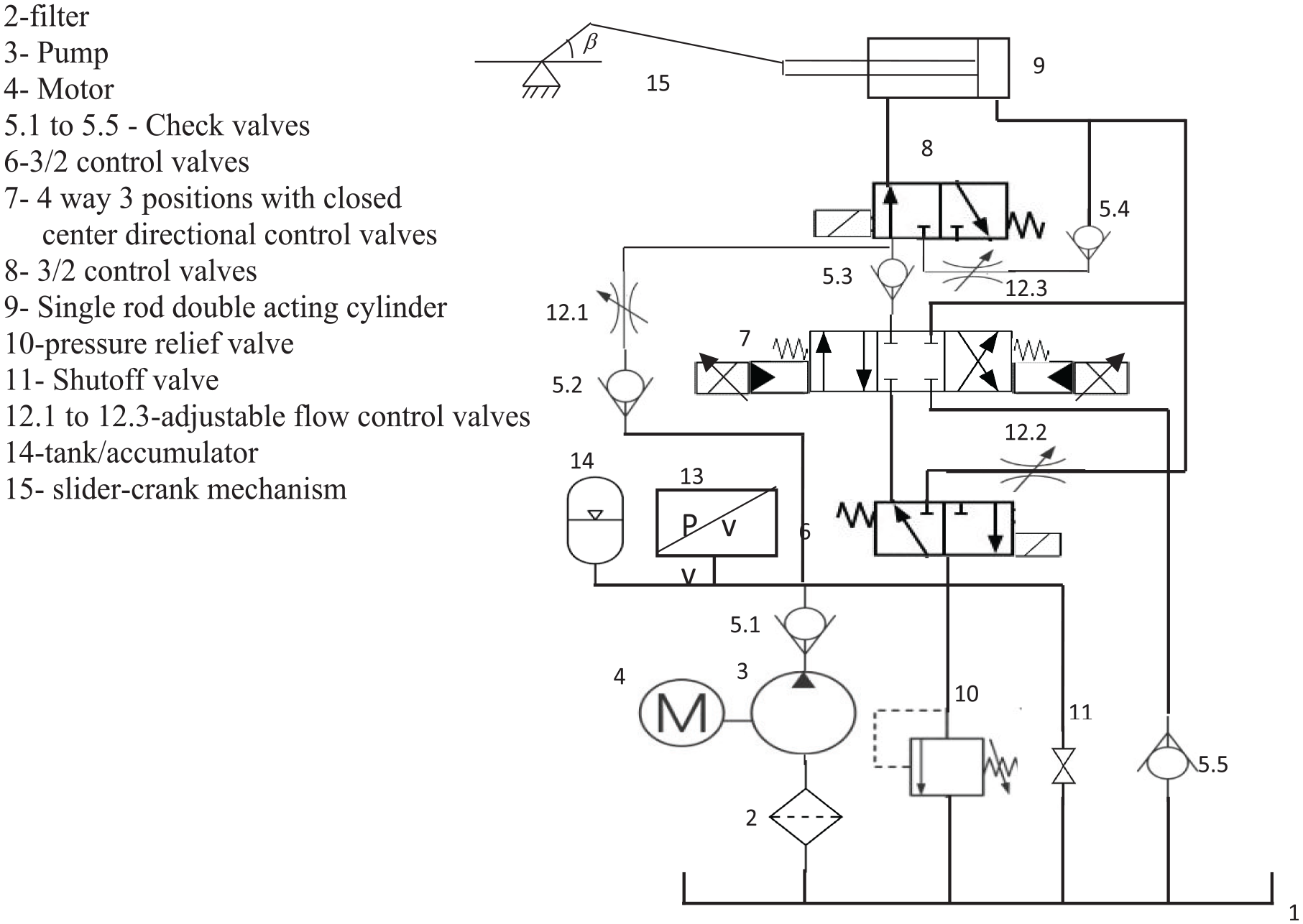
Simplified diagrams of the electro-hydraulic actuator of pitch angle.
The mathematical model of an actuator of the pitch angle of the wind turbine blade is represented (Iqbal et al., 2020; Jia et al., 2021; Jiao et al., 2019; Pathak and Gaur, 2020) by a simplified low-order model. Such representations may be acceptable for the electrical pitch systems. The hydraulic actuator model was represented using an approximation (Hosseini et al., 2019). However, the approximate model for the hydraulic pitch actuator does not account for the potential damping possibilities that may emerge from actively fluid power systems to reduce loads on the wind turbine structure. This refers to the hydraulic actuator’s flexibility as a result of oil compressibility, and how this could be used to reduce loads on the wind turbine structure. It allows the blades to deflect (pitch out of the wind) at instant of wind gusts.
The control of the hydraulic pitch actuator of the wind turbine blade considers its performance improvement by using the proportional-integral (PI) controller (Cho et al., 2020). Proportional-integral-derivative (PID) controlled hydraulic pitch actuator, and Type-2 Fuzz logic-based pitch-angle control scheme (Naik et al., 2020) and fuzz logic-based PID controller is employed for the speed control of wind energy conversion system (Haile et al., 2021). The neuronal network, fuzzy logic, and neuro-fuzzy-based PI controllers are employed for pitch angle control of the wind turbine (Pandey et al., 2022; Soufyane et al., 2020). However, the overall performance of the wind energy conversion systems under varying wind speeds is not good.
When the wind energy conversion system is subjected to excessive wind speed, the rotor speed of the turbine goes above the allowable limit. To this, the power output also increases above rated and it may cause damage to the mechanical component of the system. Also, the varying wind causes fluctuations in the torque of the drive train and output power of the turbine (Habibi et al., 2017; Ren et al., 2018). To avoid such an effect, two independent controllers of the wind turbine in partial load and full load modes were used according to the status of wind speed (Sahoo et al., 2020). This causes the control system more complex and bulky size (Apata and Oyedokun, 2020; Habibi et al., 2022; Soufyane et al., 2020). To overcome the aforementioned constraints, this study proposed an optimal fractional order proportional-integral-derivative (FOPID) controller for the pitch angle of the wind turbine blade.
The novelty of this paper is by controlling only the pitch angle of the wind turbine blade; the wind turbine mechanical dynamics performances like tip speed ratio, rotor speed, power conversion coefficient, turbine rotor-developed torque, and rotor output power are controlled, reducing the complexity and bulky size of existing pitch angle control system of the wind turbine.
The paper is organized as follows. Section “Mathematical modelling” considers the dynamic mathematical model of the plant, in section “Pitch actuator controller design” the fractional order PID controller and its optimization algorithm are presented, section “ Result and discussion” ponders simulation results and discussion about the efficacy of the hydraulic pitch actuator when the system operates under different wind considerations. Lastly, in section “Conclusion” the overall work is summarized with concluding remarks and recommendations.
Mathematical modeling
Model of hydraulic variable pitch actuator
The mathematical model of the hydraulic pitch actuator is formulated based on the principle of Bernoulli’s equation and mass conservation laws. In the operation of the directional control valve, the electromagnetic force and the spring force must be balanced. This relation can represent mathematically (Cho et al., 2020; Kong and Wang, 2007 as in equations (1) and (2).


Where

The equation of the displacement of the crank connecting rod mechanism is derived by considering the operation of the hydraulic variable pitch angle of the wind turbine blade as depicted in Figure 2.
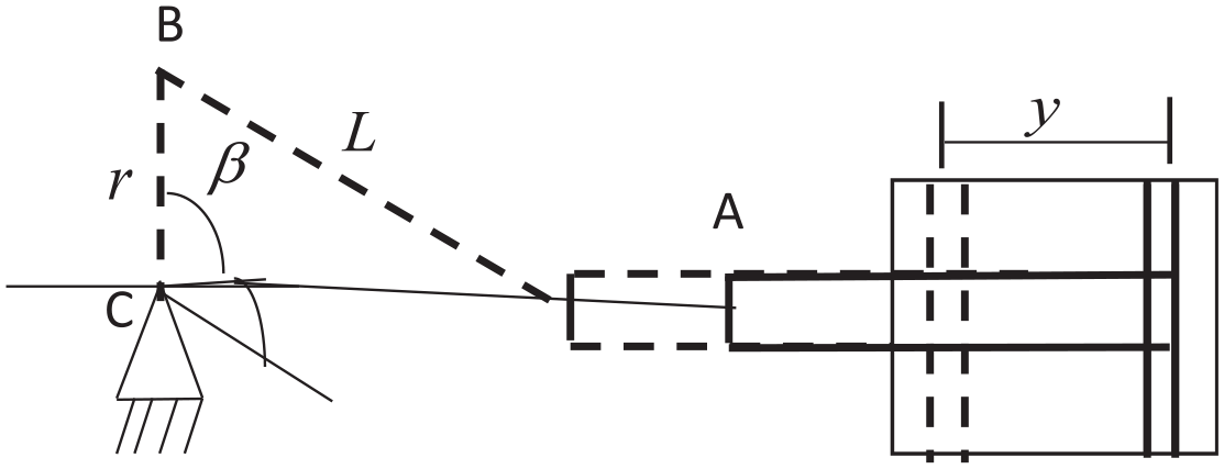
A slider-crank mechanism of the hydraulic variable pitch angle of the blade.
The displacement of the effective area of a hydraulic cylinder and the pitch angle of a wind turbine blade must be proportional, meaning that the wind turbine pitch angle varies with every change in the position of the piston. The relation between the positions of a piston of the hydraulic cylinder and the blade pitch angles is obtained based on the triangle relation, and Pythagorean identity.

Where L is the length of the link liver, r is the length of the crank, y is the displacement of the piston of the cylinder, β is the pitch angle, and

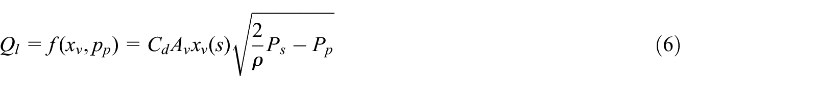
The equation of the flow of fluid through the orifices of the directional control valve is the function of spool displacement and the output (load) pressure. Accordingly, the flow equation of the directional control valve can be represented as (Phan et al., 2021).
Where

Where

Where

Where Ac is the area of the rod-less chamber of a cylinder,

Where

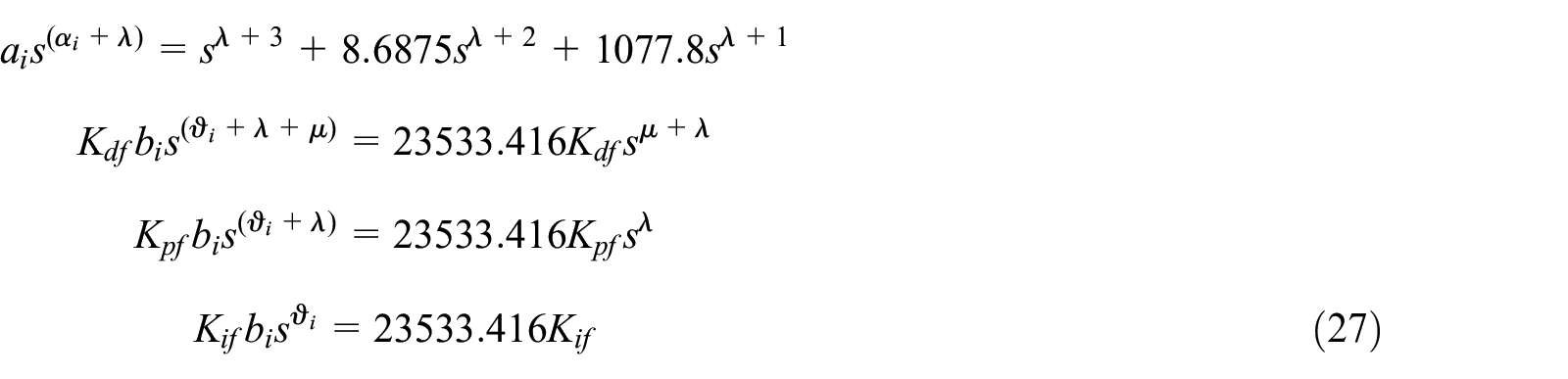
Where M is the equivalent mass of the cylinder and load. In the frequency domain, from equations (7) and (9) solve for Pp(s) and putting the result into equation (12) the general hydraulic system equation becomes
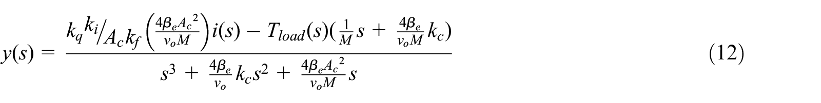
Based on the above equation the transfer function of the overall system is
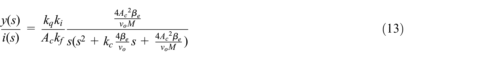
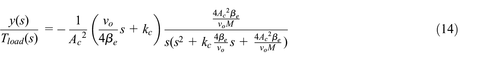
The first relation is between the input signal (electric current) of the proportional control valve and the displacement of the piston of the hydraulic cylinder. The second shows the relation between the displacement of the piston of the hydraulic cylinder and load torque. Substituting equation (5) into equations (13) and (14), and using the data in Appendix 1, the relations between the blade pitch angle of the wind turbine and input electric current to the proportional control valve, and the blade pitch angle of the wind turbine and the load torque are, respectively


Model of wind turbine
The mechanical power (

Where the radius of the rotor of the turbine is
Where

The rotor angular speed of the wind turbine (Monje et al., 2010) is

Where

At any wind speed by controlling the pitch angle of the blade (
Pitch actuator controller design
Without the controller, the hydraulic actuator for the pitch of the wind turbine blade equation (15) is unstable. Thus, the control techniques must stabilize this system mandatory. In this paper optimal controllers of the proportional integral and derivative (PID) and fractional order PID are considered. To improve the performance of the overall system fractional order controller is more power full than the integral order controller (Gundtoft, 2012). Hence, a general form of the PID controller, which is called the fractional order
The differential equation of the fractional order

The orders of integral and differentiation can be represented based on the relation between two axes. From equation (22) the control space of FOPID can be seen that the conventional PID-type controllers are just a few specific points on the order planes. However, the orders of the controllers in fractional-order PID controllers can be arbitrarily chosen in the range

Where

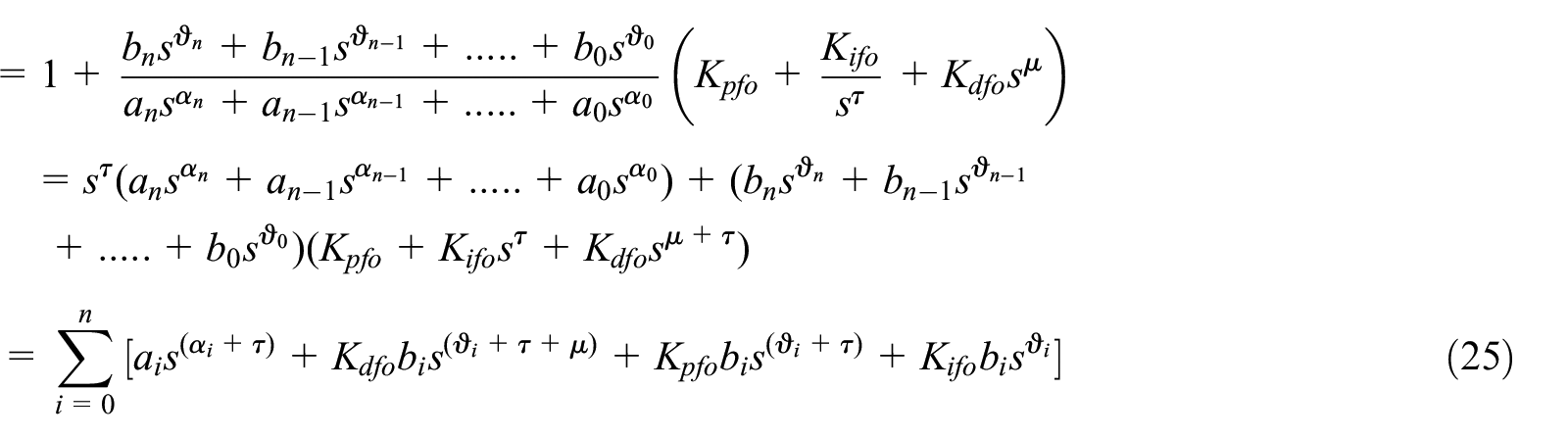
Where n + 1 is the total number of coefficients of the denominator of the equation (15) of the plant. The operation range of the parameters of both controllers is determined by considering the stability of the overall system. Using the hydraulic actuator model (15) into equation (25) with the order of plant is three and all b3, b2, b1, and a0 are zero and b0, a3, a2, and a1 are 23,533.416, 1, 8.687, and 1078, respectively. Thus, equation (25) is equally written as

Comparing equations (26) and (25), the characteristic equation components can be related as
Applying analyses of Real Root Boundary (RRB) at s = 0, Complex Root Boundary (CRB) at
Controller’s parameter for GA optimization.
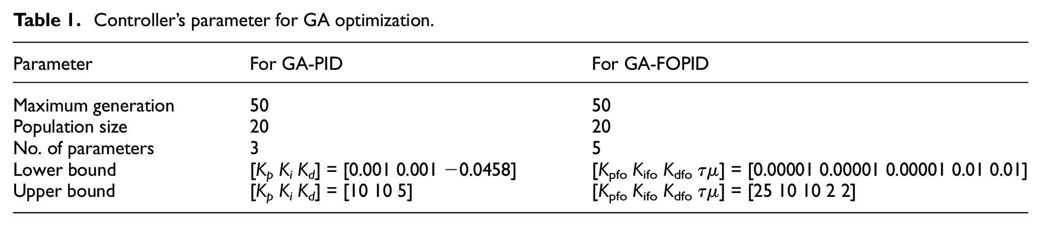
The analytic approach is not convenient to get the optimal values of the parameters of the controllers. These are determined by using the Genetic Algorithm (GA) as depicted in Figure 3. That is a search-based optimization technique. The controller parameters tuning is often transferred to an optimization problem, formulated as

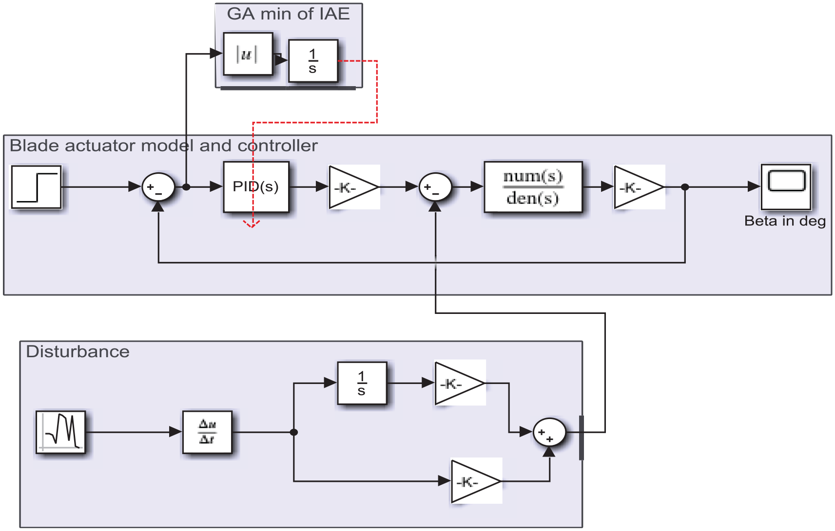
Simulation diagram of a hydraulic actuator of the pitch angle of the blade of the wind turbine.
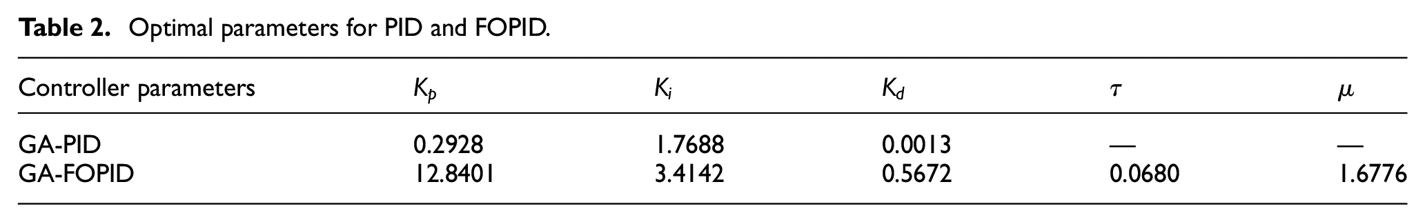
This is the integral absolute error (IAE), which is adopted as the cost function; where e(t) is the error between the actual pitch angle and the desired value. As seen in Figures 4 and 5, the fitness function-IAE becomes zero at the sixth iteration for FOPID at which the values of the parameters of the controllers are optimal; whereas for PID the IAE is not zero until the 36th iteration. Using the genetic algorithm, the optimal parameters of the controller are shown in Table 2.
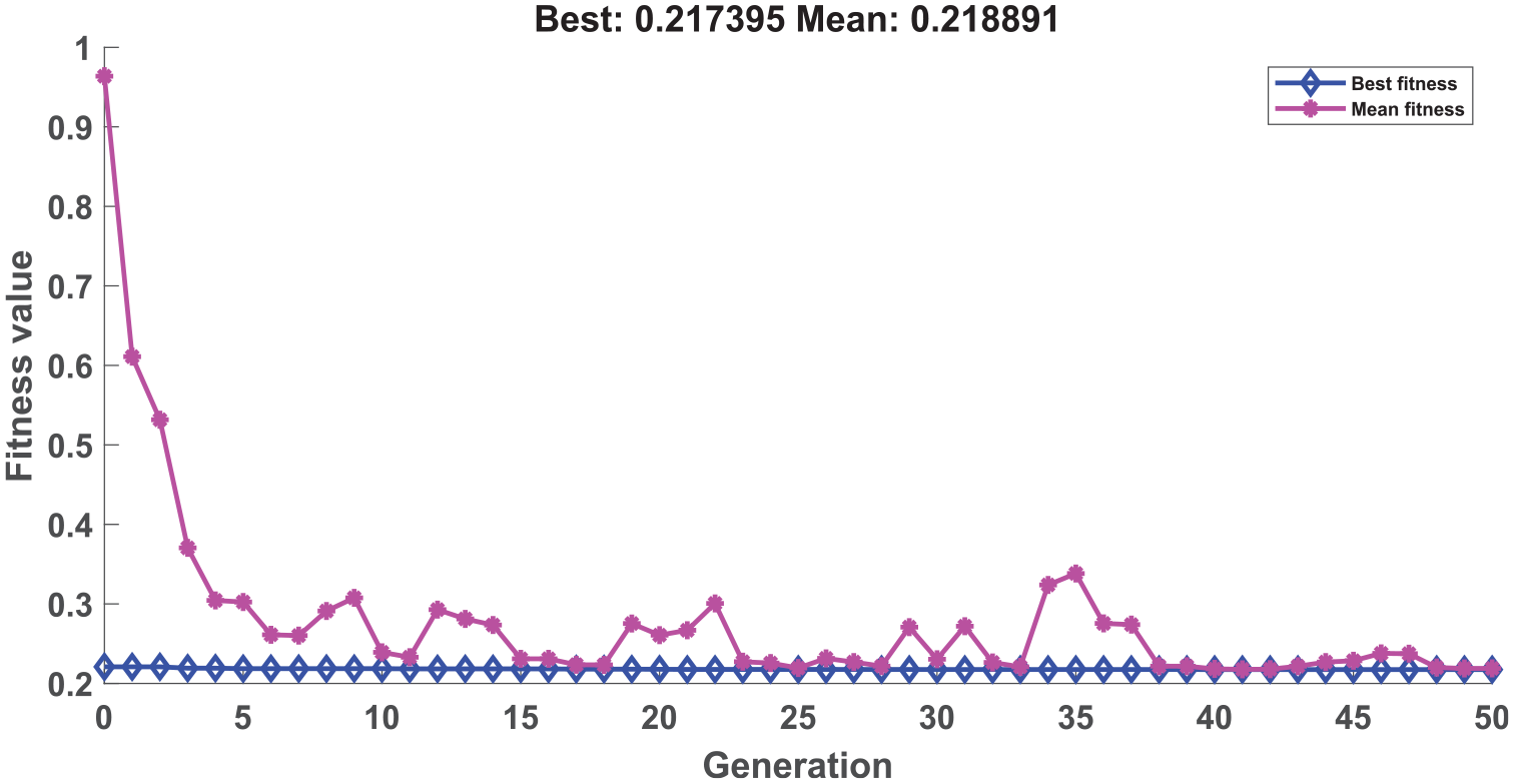
GA generation versus fitness value graph for PID.
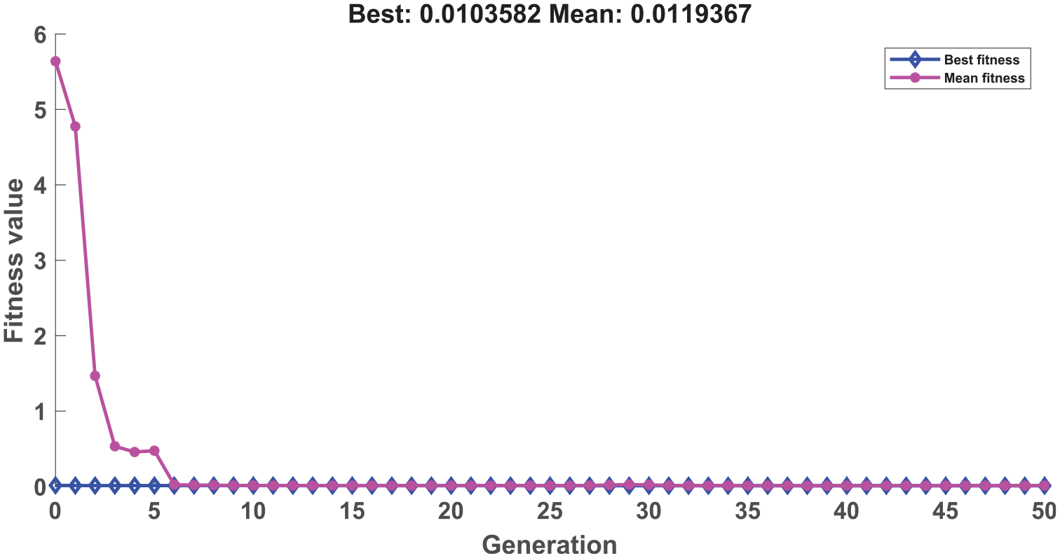
GA generation versus fitness value graph for FOPID.
Optimal parameters for PID and FOPID.
Result and discussion
This section considered simulation and performance analysis of the proposed controller of the hydraulic pitch angle actuators for the blade of the wind turbine and their effect on the mechanical dynamics performances of the wind turbine.
Controller performance
Naturally, the wind is changing stochastically and affects the overall operation of the wind energy conversion system. In this paper, the wind is represented by a stochastic signal as in Figure 6. It varies between 1.6 and 18.3 m/s around the hub height, which includes both low and high wind speed incidents and helps to test the performance of the controllers of pitch angle under different operating conditions. Thus, the effect of pitch angle controller performances on the turbine dynamics is investigated. The desired pitch angle is obtained when the controller of the actuator satisfies good reference tracking ability. Under varying references, the proportional directional control valve drives the hydraulic cylinder piston to set the turbine blade at desired pitch angle. In this case, the performance of the controller is measured based on the value of integral absolute error (IAE) by simulating Figure 3 using the wind speed in Figure 6.
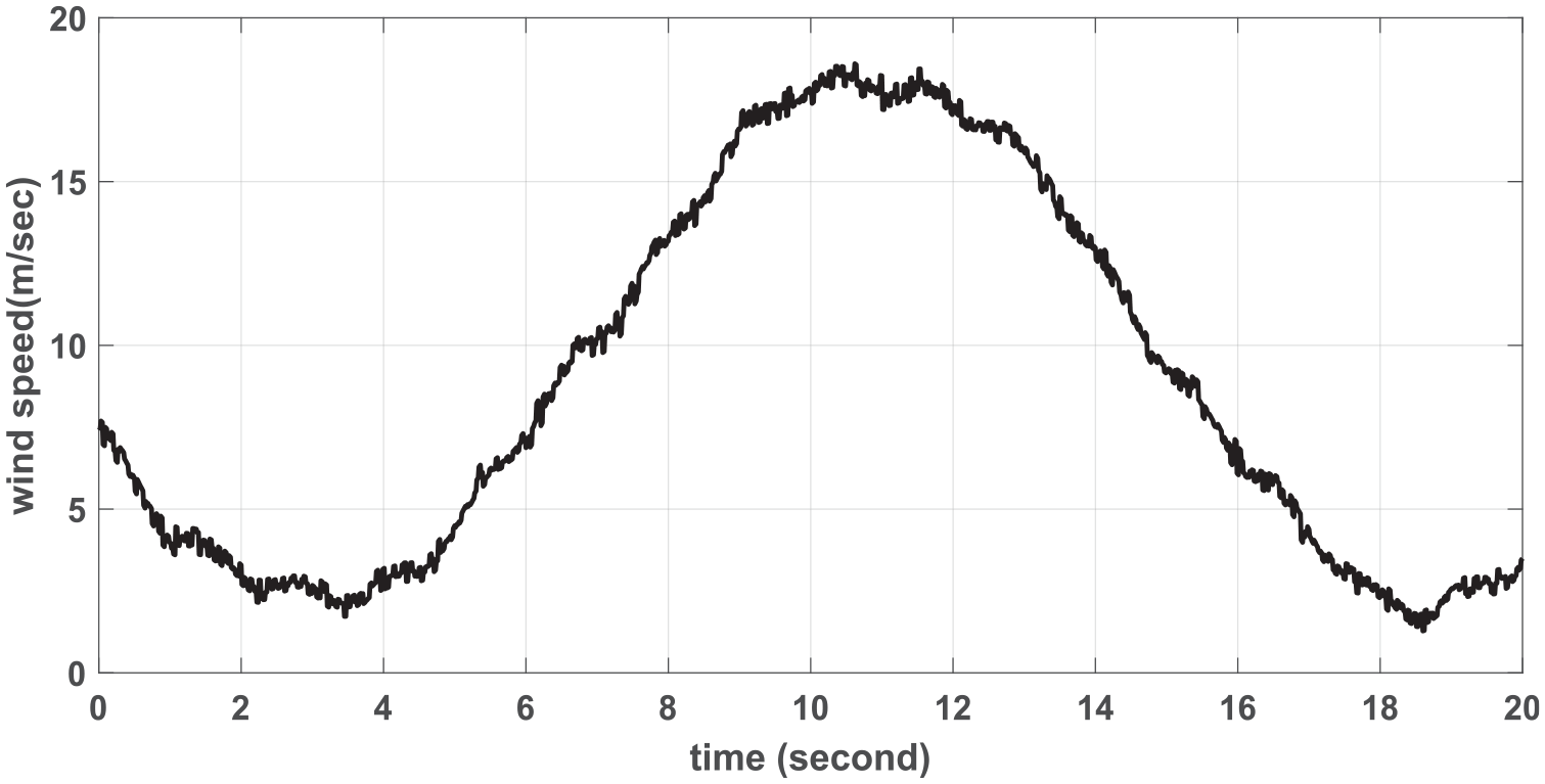
Continuous variable wind speeds.
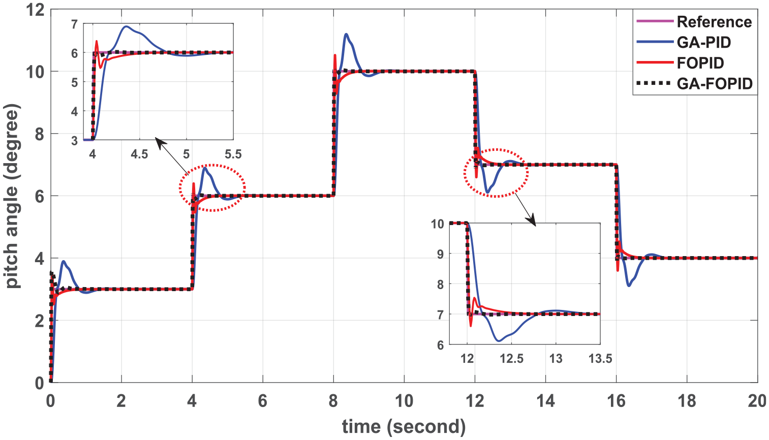
The pitch angle simulation results are presented in Figure 7 which is stabilized by the controllers. This Figure shows the pitch angle response of the three controllers; the GA-PID controlled pitch angle varies between 15.769° and −0.22°, the one controlled by FOPID varies between 15.476° and 0°, and the third one is controlled by GA-FOPID varies between 15.204° and 0°. These indicated the GA-FOPID controlled pitch system had a smooth pitch angle response than conventional PID-controlled pitch output. Smooth pitch control actions are essential for removing fluctuations in the output power and drive-train torque.
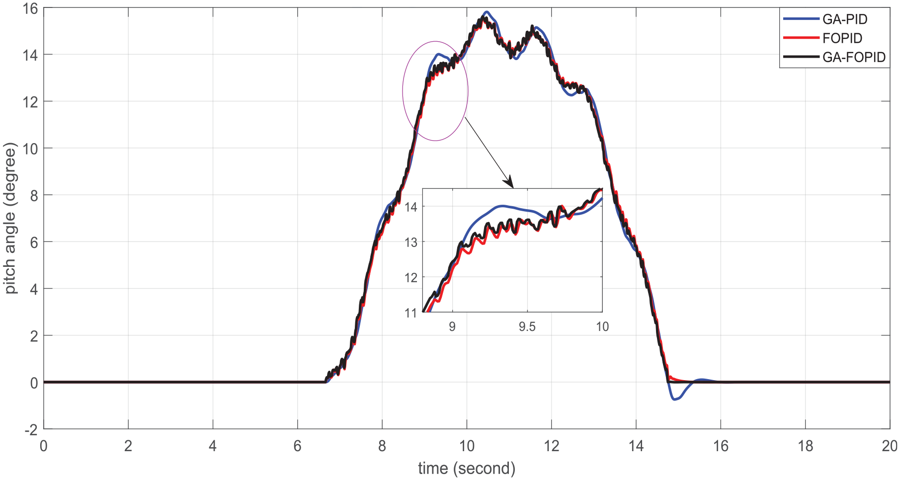
Pitch angle response for FOPID, GA-FOPID, and GA-PID under variable wind speed.
From Figure 8, initially, the value of the error between the desired pitch angle and the actual response is 10. That is initially all controllers PID, FOPID, and GA-FOPID have the same error. However, the steady-state error response from the GA-FOPID is better near zero than that from the two controllers. This indicates the GA-FOPID has a better capacity to reduce error than the other two control techniques.
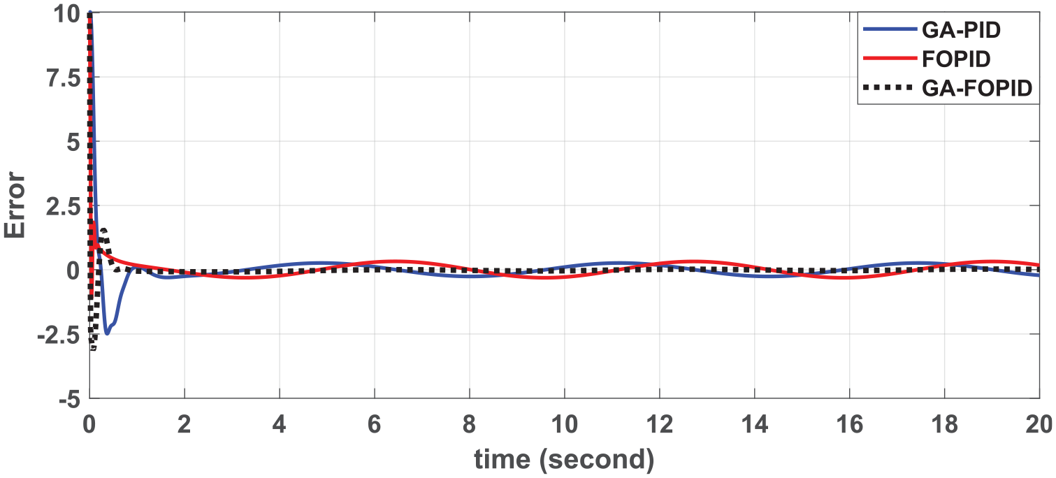
Sinusoidal reference signal tracking error for GA-PID, FOPID, and GA-FOPID.
Due to the effect of wind gusts, there may have a sudden change in the wind speed around the wind turbine. The effects are reduced by changing the turbine blade pitch angle as depicted in Figure 9. From this Figure, the value of the error of the controllers PID, FOPID, and GA-FOPID are 4.0, 0.6031, and 0.2506, respectively. Thus, the GA-FOPID has better error reduction performance than other types of control techniques. In other words, the GA-FOPID controller reduced the error by 93.735% concern to that of GA-PID, and it reduced the error by 58.448% concerning that of the FOPID controller.
Pitch angle responses for FOPID, GA-FOPID, and GA-PID under staircase reference signal.
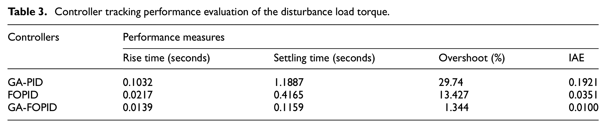
Table 3 shows the performance of the controllers for unity step tracking response under the effect of the disturbance-load torque. According to the comparison in this Table, GA-FOPID has a better performance measurement (settling time, overshoot, and IAE) than FOPID and GA-PID.
Controller tracking performance evaluation of the disturbance load torque.
Performance of the controlled wind turbine under variable wind speed
The overall simulation is performed using a complete system diagram as in Appendix 2. It is a logically connected model of the rotor output power, the tip speed ratio, the power conversion coefficient, rotor speed, and rotor output torque of the wind turbine, and the model of the hydraulic pitch actuator of the wind turbine blade, and the controller. Once the optimal controller is designed, the Simulink model for the overall system is ringed by sequentially integrating the aforementioned components that their mathematical models are depicted in equations (15)–(22).
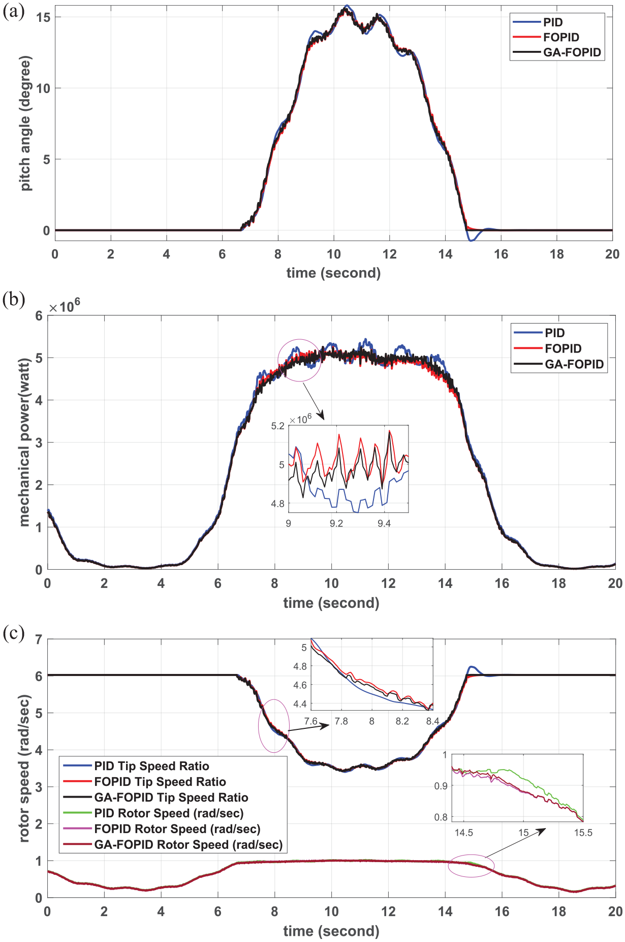
Figure 10 shows the tip speed ratio and rotor speed response of the turbine under the proposed controllers. Below rated wind speed, the tip speed ratio of the turbine is a high value since the pitch angle is settled around 0°. In this case, the GA-PID produced a tip speed ratio of 5.89, and both FOPID and GA-FOPID produced a tip speed ratio of 5.686. That is the maximum tip speed is recorded when the pitch angle is around 0°. Because, at this instant, the wind hits all flat portions of the turbine blade. At the wind speed is above the rated value, the pitch angle of the turbine blade is increased; this reduces the portion of the wind that hits the blade. Thus for the wind speed above the rated value, the value of the tip speed ratio from controllers PID, FOPID, and GA-FOPID are 3.214, 3.22, and 3.24, respectively.
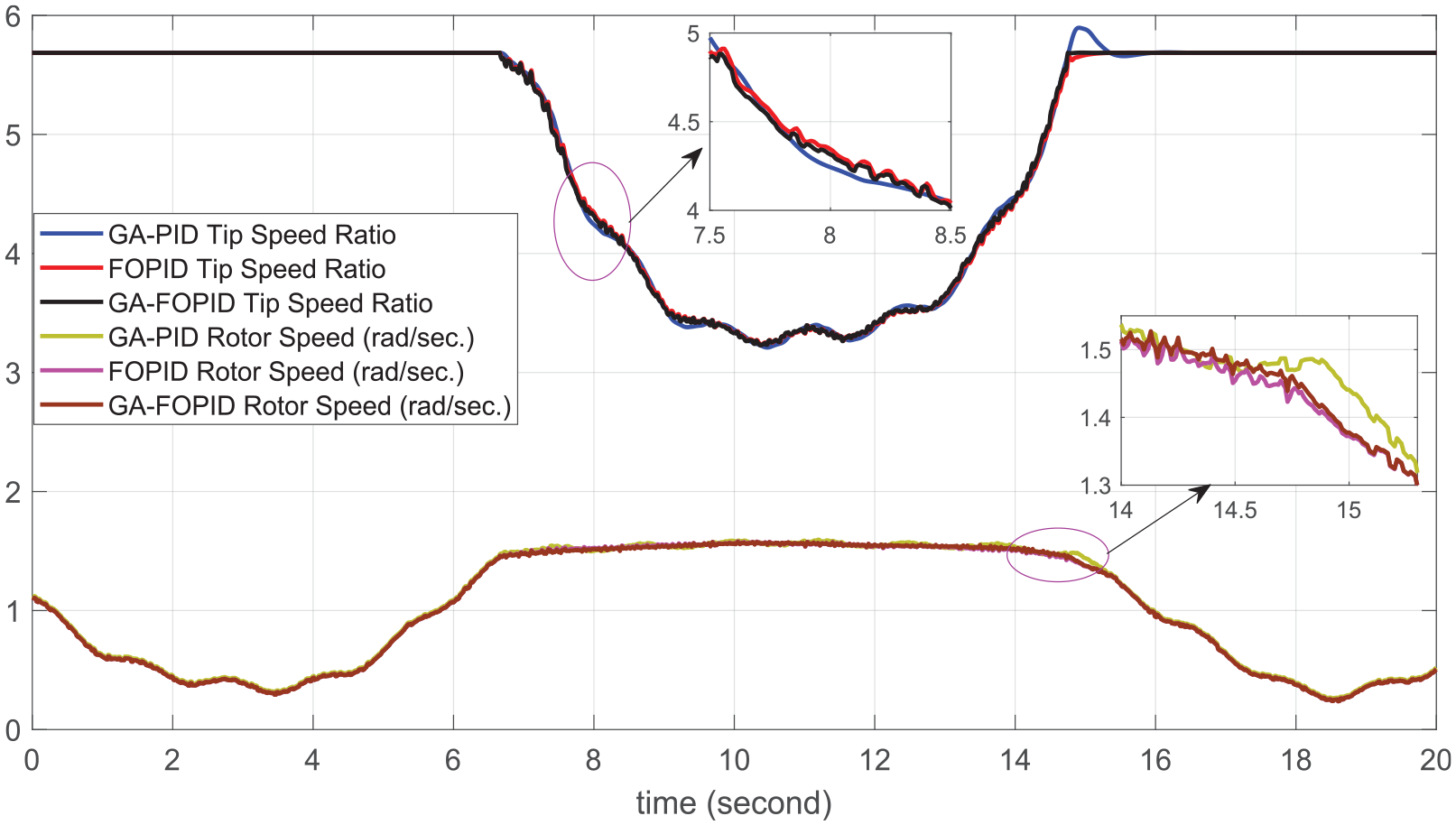
Tip speed ratio and turbine rotor speed responses for FOPID, GA-FOPID, and GA-PID controllers under variable wind speed.
From Figure 6, between 7.5 and 14.5 seconds, the input wind speed to the wind energy conversion system is above the rated wind speed which drives the blade at a higher speed than the rated value which may cause mechanical damage. Under these circumstances, however, the rotor speed of the turbine settled to the value between 1.517 and 1.585 rad/s, 1.514 and 1.576 rad/s, 1.517 and 1.598 rad/s by GA-PID, FOPID, and GA-FOPID controllers, respectively. All these values are below and near the rated rotor speed (1.676 rad/s) of the turbine. The result indicates that the rotor speed which is controlled by the GA-FOPID closer to the rated value with 5.43% variation.
As indicated in Figure 11, the power conversion coefficient of the wind turbine has a great role in power regulation, it has an inverse relation with blade pitch angle. At lower wind speed the power conversion coefficient has a higher value, and when wind speed increases above the rated value the pitch angle of the blade increases which reduces the power conversion coefficient. Thus, it limits the mechanical output power of the turbine.
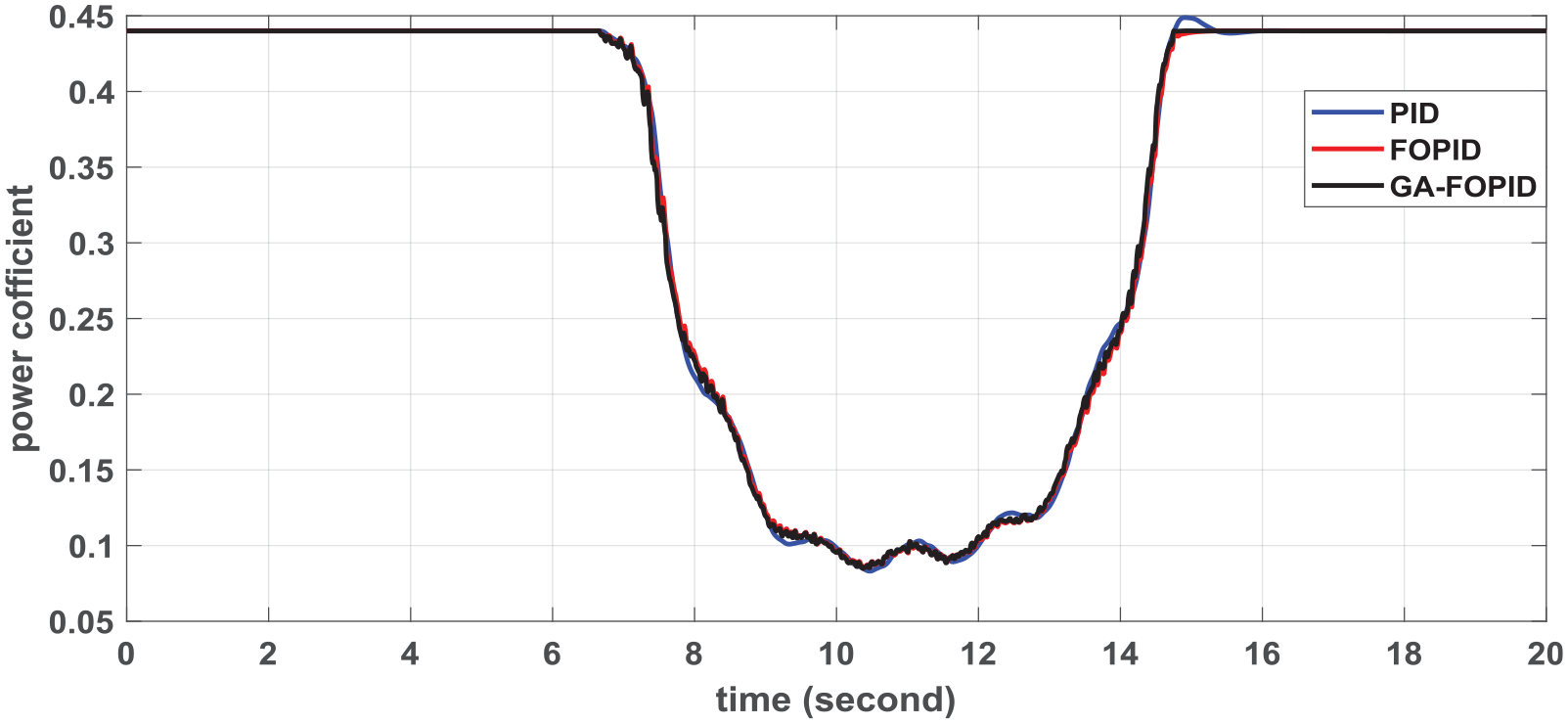
Power conversion coefficient for FOPID, GA-FOPID, and GA-PID for variable wind speed.
Considering the mechanical power output of the turbine rotor, it varies between 1.528 and 1.39, 1.526, and 1.415 MW, and between 1.512 and 1.426 MW under the use of the GA-PID, FOPID, and GA-FOPID-based pitch controllers, respectively. This is depicted in Figure 12. These values are before losses in the dive-train between the turbine and generator. Accordingly, the GA-FOPID-based pitch controller significantly reduced fluctuations in the output power to 0.08% and maintains it around the rated power (1.5 MW) as compared with the conventional GA-PID-based pitch controller which has 1.87% fluctuations in the output power. As seen in Figure 12, the mechanical torque that is developed by the turbine rotor is simulated. This is used to drive an electric generator through a drive-train.
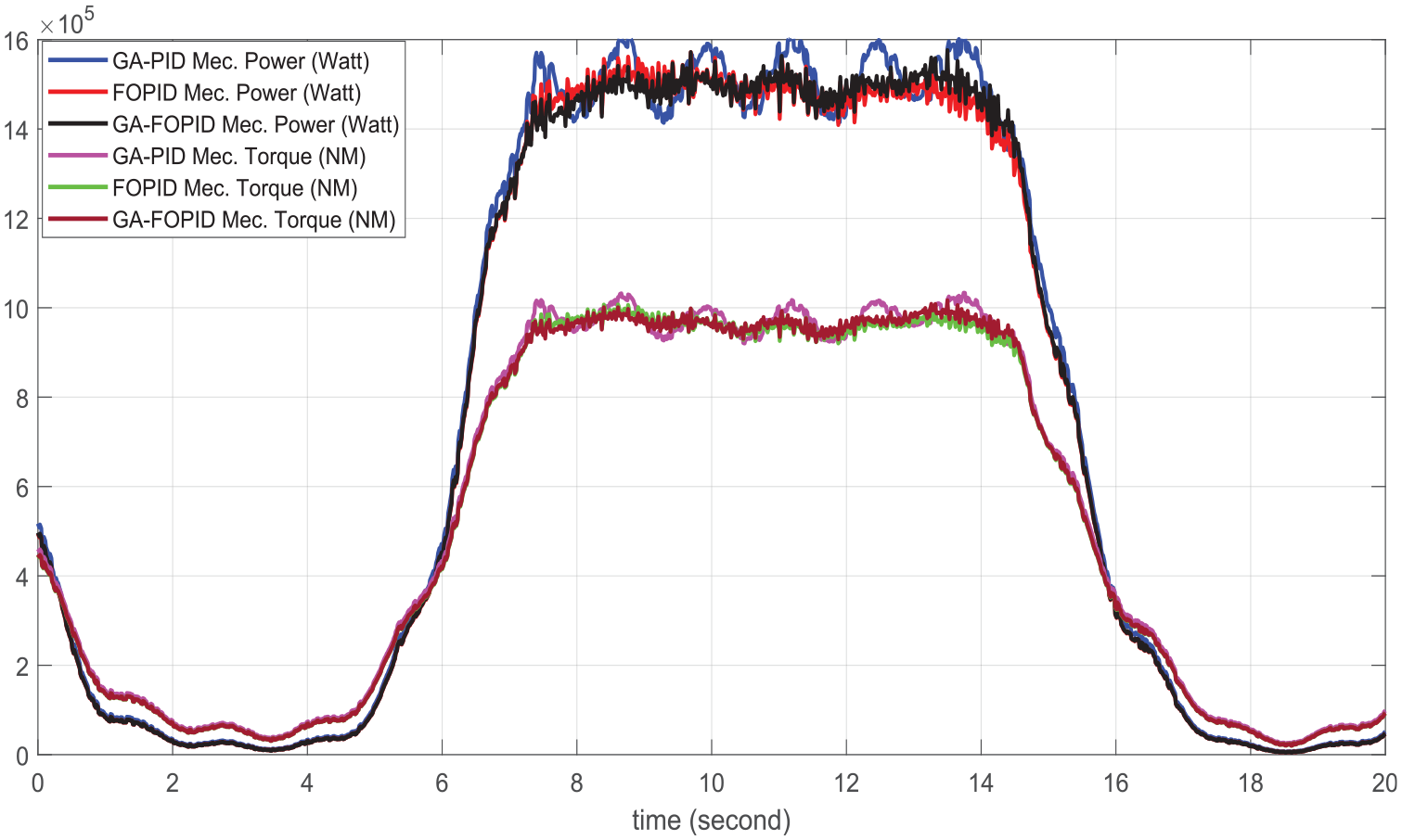
Output mechanical power and mechanical torque of the turbine for FOPID, GA-FOPID, and GA-PID controllers under variable wind speed.
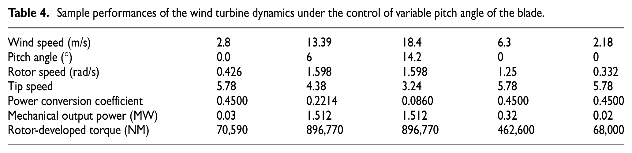
The GA-based FOPID pitch angle controller maintained the rated mechanical torque even under variable wind conditions and can mitigate drive-train torque fluctuations regardless of variable wind conditions. The summarized sample of performances of the wind turbine that is controlled by GA-FOPID is presented in Table 4. From the above sample performances of the turbine dynamics are measured when the wind speed varies between 2.18 and 18.4 m/s. For the wind speed above 11 m/s, the blade pitch angle increases to reduce the effect of mechanical overload on the overall system. An increment in the blade pitch angle reduces the values of the tip speed ratio and the power conversion coefficient. These limit the output power, mechanical torque, and rotor speed around the rated value of the system.
Sample performances of the wind turbine dynamics under the control of variable pitch angle of the blade.
Furthermore, the proposed pitch control technique is validated by implementing it on a 5 MW wind turbine which has rated rotor speed 1.25 rad/s, rated wind speed 14 m/s and blade length of 63 m. Considering the same wind speed that is used for 1.5 MW is applied to 5 MW wind turbine, the simulation results of pitch angle, mechanical output power, tip speed ratio and rotor speed are depicted in the Figure 13. All are well controlled and regulated to rated values of the machine. This indicates proposed pitch control technique can be used to any size of wind turbines only by updating specifications of machine to be controlled.
5 MW wind turbine simulation results of (a) pitch angle, (b) mechanical output power, and (c) tip speed ratio and rotor speed.
Conclusion
The modeling of the hydraulic pitch angle actuator of the wind turbine blade is presented and the GA-PID, FOPID, and GA-FOPID are employed in the control of this actuator. The controllers correct the position of the directional control valve spool to alter the pitch angle of the turbine using a slider crank mechanism that fixes at the root of the turbine blade. The performance of these three controllers is measured by considering variable wind conditions. The pitch angle of the turbine blade is adjusted according to the wind status. The simulation results show that by altering the pitch angle the proposed controllers regulated the turbine mechanical output power, torque, rotor speed of the turbine, and the tip speed ratio of the blade. At rated wind speed the simulation result of these three controllers are compared and the GA-FOPID has 0.08% fluctuation in the output power, which is a better performance than that of the other two controllers. This study can be further improved by cooperating fault detection mechanisms for the hydraulic actuator such as oil leakage.
Footnotes
Appendix
Specification of a 1.5 MW wind turbine (Kong and Wang, 2007; Majout et al., 2022).
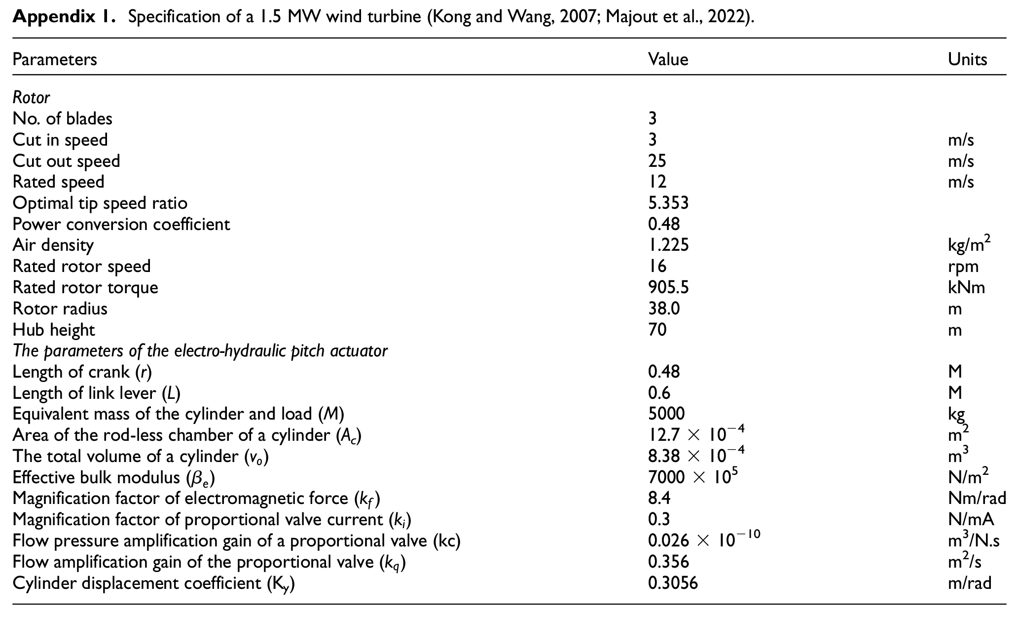
| Parameters | Value | Units |
|---|---|---|
| Rotor | ||
| No. of blades | 3 | |
| Cut in speed | 3 | m/s |
| Cut out speed | 25 | m/s |
| Rated speed | 12 | m/s |
| Optimal tip speed ratio | 5.353 | |
| Power conversion coefficient | 0.48 | |
| Air density | 1.225 | kg/m2 |
| Rated rotor speed | 16 | rpm |
| Rated rotor torque | 905.5 | kNm |
| Rotor radius | 38.0 | m |
| Hub height | 70 | m |
| The parameters of the electro-hydraulic pitch actuator | ||
| Length of crank (r) | 0.48 | M |
| Length of link lever (L) | 0.6 | M |
| Equivalent mass of the cylinder and load (M) | 5000 | kg |
| Area of the rod-less chamber of a cylinder (Ac) | 12.7 × 10⁻⁴ | m2 |
| The total volume of a cylinder ( |
8.38 × 10⁻⁴ | m3 |
| Effective bulk modulus ( |
7000 × 105 | N/m2 |
| Magnification factor of electromagnetic force ( |
8.4 | Nm/rad |
| Magnification factor of proportional valve current ( |
0.3 | N/mA |
| Flow pressure amplification gain of a proportional valve (kc) | 0.026 × 10⁻¹⁰ | m3/N.s |
| Flow amplification gain of the proportional valve ( |
0.356 | m2/s |
| Cylinder displacement coefficient (K y ) | 0.3056 | m/rad |
Acknowledgements
We are very grateful to all who contributed directly or indirectly to the work of the study whose names are not mentioned here, mainly friends and family for sharing their knowledge and materials and Adama Science and Technology University and Adama Wind Farm for facilitating the study.
Contributions
The main contribution of this work is:
It introduces the model of the hydraulic pitch actuator of wind turbines.
It introduces simple and optimal control techniques for the hydraulic actuator-based variable pitch of variable-speed wind turbines.
It contributes to a better understanding of variable speed wind turbine control techniques that control the mechanical output power, torque, rotor speed, and tip speed ratio of wind turbine only by controlling pitch angle; and their modeling as well as control concepts taking account of performance indexes.
It helps in reducing a large percentage of wasted wind power using appropriate control techniques.
Declaration of conflicting interests
The author(s) declared no potential conflicts of interest with respect to the research, authorship, and/or publication of this article.
Funding
The author(s) received no financial support for the research, authorship, and/or publication of this article.
Data availability
The data underlying the findings of this study are included in the article and the parameters of the machine along with others have been given in the manuscript. No other data have been copied from any other papers and are not implemented wrongly.