
Abstract
Background:
There are many associated devices using impedance method. However, they cannot completely suppress tremor. Other methods using active vibration control have been a challenging problem for industrial and academic researchers. Potential applications of the latter for tremor patients are still not realized.
Objectives:
This article presents a novel method for suppressing human lower arm tremor in essential tremor by using a self-balancing technique.
Study design:
In this article, a rotating unbalanced mass actuator was used to imitate an arm tremor with the same frequency range obtained from clinical sources. A novel counter-balance device was designed to attach the fictitious arm. The tremor reduction is expecting quantitatively.
Methods:
A Proportional–Integral–Derivative controller and an algorithm programmed in LabVIEW are proposed to control a rotating unbalanced mass actuator, anti-shaker, in order to counter the tremor. The self-balancing system for the new approach was obtained when both amplitudes and frequencies of anti-shaker and tremor are the same.
Results:
The results show that this method can reduce vibration of tremor in the order of 0.001 rad/s2.
Conclusion:
This method can suppress the vibration and can also auto-tune to counter the tremor in a range of 4–12 Hz bandwidth.
Clinical relevance
The therapy of arm tremor was associated with using counter-devices to palliate the vibration magnitude. Conventional methods such as physical surgery and drugs cannot completely eliminate tremor. The novel counter-device is an alternative technique with promising application for clinical uses for tremor patients without involving harmful surgery.
Background
Essential tremor (ET) is a slowly progressive neurological disorder, the most recognizable feature of which is the tremor of arms 1 or hands that occurs during voluntary movements. 2 ET occurs approximately 4% in people aged 40 and older and much higher among people in their 60s, 70s, 80s, and 90s for both sexes.3,4 Tremor frequency of ET usually ranges from 4 to 12 Hz. 5 The frequency of tremor declines and amplitude increases with age. 6 The amplitude of the tremor can be mild or severe. When severe, it can be disabling and can result in difficulty in many daily living tasks. Only a small percentage of individuals with mild to moderate ET come to medical attention. ET is likely due to an overactivity of a generator located in posterior fossa (brainstem—cerebellum) and interacting with thalamo–cortical pathways. 7
For many decades, physical and drug therapies have been used to eliminate tremor but cannot provide a successful treatment. Physical therapy such as muscle control, muscle strength, and tremor positioning can only treat minor cases of ET. Severe tremor can be treated with medication or surgery but they can cause side-effects. Common side-effects of tremor medications include sedation, weight gain, nausea, diarrhea, rash, impotence, and depression. 8 Surgery is associated with a risk of hemorrhage and psychiatric manifestations. 9 In particular, a high rate of suicide (4.3%) has been observed in patients treated with deep brain stimulation. 10 Since conventional methods are not very successful, it gives rise to the need for alternative approaches to the problem of tremor suppression. Recently, there are many significant results obtained in reducing tremor by applying mass, friction, and viscous resistive force. Among them, some orthotic devices have been proposed. Pledgie et al. 11 designed a system that achieved a specified reduction in pathological tremor power through controlling the impedance of the human–machine interface. Hashemi et al. 12 proposed a tuned vibration absorber system which was very effective in the suppression of vibrations in an experimental model of the human arm with 2 degrees of freedom. Loureiro et al. 13 presented an orthotic device, which dynamically suppresses pathological tremor, by applying viscous damping to the affected limb in a controlled manner. Rocon et al. 14 proposed a wearable orthotic device, which can be adapted to each configuration of each joint of the upper limb. The wearable orthotic device can be used as a treatment for ET patients.
Fast Fourier Transform (FFT)-based spectral analysis is a very popular method of tremor quantification.8,15 Engin 16 proposed the tremor analysis on frequency and amplitude parameters by using the FFT and higher-order spectra to obtain the main peak frequency of tremor.
Another promising method is an active vibration control (AVC) approach. Rather than suppressing the actual tremor by impedance, the device that is actuated with an equal but opposite motion can be effectively used to subtract the tremor out of motion. AVC has been a challenging problem for industrial17–19 and academic 20 researchers for many years. Stone et al. 21 used the auto-tuning of a Proportional–Integral–Derivative (PID) controller for an active vibration suppression device for the treatment of ET.
In this article, a self-balancing method is presented in the form of real-time AVC to suppress arm tremor. PID controller and an algorithm were developed in LabVIEW and were used to control a rotating unbalanced mass (RUM) actuator, anti-shaker, to counter a tremor signal generated by another RUM actuator, tremor generator. This novel design can replace the conventional methods including using drugs and deep brain stimulation which could cause fatal risks. With a simple mechanism as shown in next sections, the design can be practically implemented for an orthotic device. Since this is an active device, unlike the passive or damping approaches, it allows for wide range of voluntary motion.
Method
ET is an involuntary movement. It usually occurs due to the intentional movements. The involuntary movement (high frequency) can be extracted from the intentional movement (low frequency) by using a high-pass or band-pass filter. In order to suppress the tremor, frequency, amplitude, and phase of the tremor are needed to be known. The idea is to generate the same frequency and amplitude with 180° out of phase to counter the tremor.
The amplitude of the signal generated by the RUM actuator depends on two factors: one is from the unbalanced mass of the RUM actuator (more mass, more amplitude); the other is the distance between the RUM actuator and the pivot at the elbow (the closer to the pivot, the smaller the amplitude of the signal).
The mass changing is not suitable for this experiment to meet the amplitude problem. On the other hand, the distance of the RUM actuator from the pivot is more appropriate, since it can change amplitude online during the experiment.
Assume that the amplitudes of the anti-shaker and the tremor are the same (by adjusting the distance of the anti-shaker); there are only phase and frequency to be examined. Figure 1(a) shows the top view and parameters of the system.
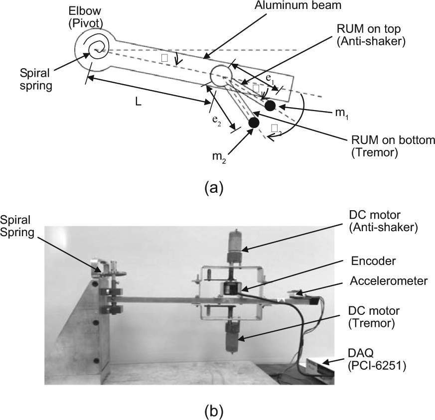
(a) Top view of the model (drawing) and (b) side view of the model (photograph).
In this research, RUM actuator was used to generate an arm tremor with the same frequency range obtained from clinical sources.8,16 All experiments throughout this article were operated by using RUM without human and animal involved.
Let θ be the angle of the beam to the equilibrium position,
θ1 be the angle of the arm of RUM actuator, anti-shaker, to the beam,
θ2 be the angle of the arm of RUM actuator, tremor generator, to the beam,
e1 be the eccentricity of anti-shaker,
e2 be the eccentricity of tremor generator,
m1 be the eccentric mass of RUM actuator, anti-shaker, and
m2 be the eccentric mass of RUM actuator, tremor generator.
Consider the equation of motion of the system in Figure 1(a).

where
The complete solution θ(t) for the equation (1) is

and the θh(t),


where ωd is the damped natural frequency; ϕd is the phase due to initial conditions,
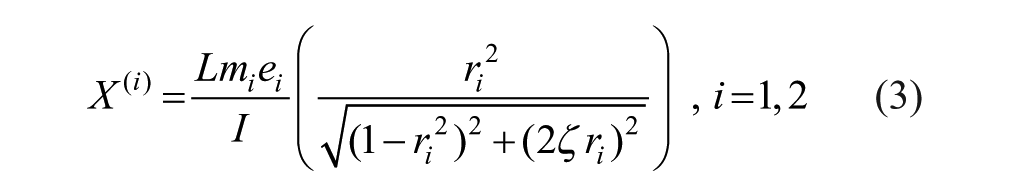


Let us consider some cases for investigating the minimum vibration of the system, where the steady state response of angular displacement is

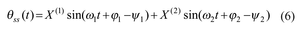
Since at any angular speed of both RUM actuators, whether under the first-order critical angular speed (corresponding to the rigid rotor) or above the first-order critical angular speed (corresponding to the flexible rotor), the initial phase difference of both RUM actuators driving force is equal to the phase difference of vibration displacement caused by the two driving forces respectively, and vice versa. 22
By substituting parameters I = 7 × 10⁻⁴ kg/m2, e1 = 5 cm, e2 = 5 cm, m = 0.015 kg, ωn = 0.8 rad/s, ω = 2
Case 1: ω1 = ω2 = ω, and m1 = m2 = m.
As seen from Figure 4, at phase difference of 180°, the RMS is 0.

where
Case 2: ω1 = ω2 = ω, m1 = m, and m2 = 2 m.

where ϵ is the minimum RMS. Noting that ϵ occurs at Δ = 180°.
Investigation of steady state response
With the following three tests on both RUM actuators (Figure 1(a)) and by using the same parameters of the simulation with the model in Figure 1(b), the fact of nature done on the system can be revealed.
Test 1: Different initial angles with same mass and frequency
Examining the initial angles between both RUM arms with the same mass rotated at the same frequency result that, for the acute and obtuse initial angles, the rotations for both arms at the steady state have the same result which is 180° apart.
Test 2: Different initial positions of different mass
Examining the initial position of different mass between m1 and m2 (m2 > m1) leads to the results that the leading mass at the final state is always the heavier one regardless of the initial position.
Test 3: Different mass, same frequency
Examining the different mass for both RUM arms rotating at the same frequency reveals the results as shown in Table 1.
Comparing of mass m2 and final angle of rotation.
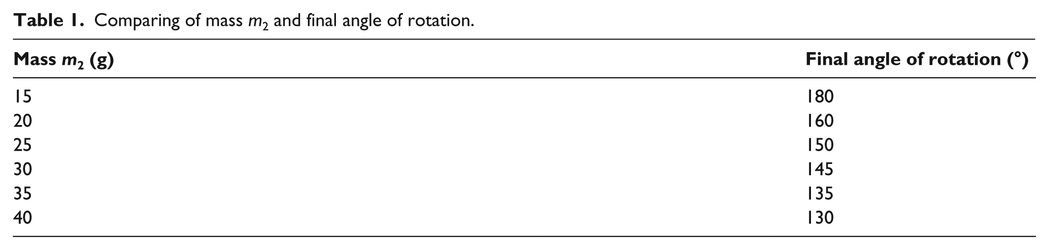
Figure 2 indicates the relationship between the simulation and experiment results of the differences in mass m2 and RMS values. The experiment result shows that the more mass of m2, the less phase difference at final state.
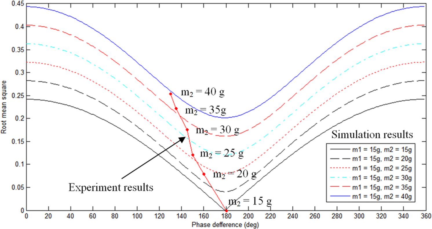
Simulation and experiment results of the differences in mass m2 and root mean square.
This means that increasing mass m2 will dominate the rotation of both the RUM actuators and will cause the phase difference at final state to decrease. The tests about the nature of rotating of unbalance mass above inspired the design of the mechanical device in this experiment, especially in Test 1 (m1 = m2 = m), to use AVC and let the nature stabilize the system by itself.
Experiment procedures
Controller and algorithm
The parameter to be considered, apart from tremor amplitude and phase, is only tremor frequency which is in the range of 4–12 Hz. Frequency tracking can be achieved by using PID controller and an algorithm which will be discussed later on. The accelerometer was used to detect the frequency signals acted on the beam (tremor and anti-shaker frequency) and an encoder was attached to the anti-shaker to monitor its shaking frequency.
With the use of spectral measurements in LabVIEW, the frequencies of both actuators can be investigated. At the beginning of suppression process, the PID controller (Kp = 0.01, Ki = 0.00009, Kd = 0.003) starts to operate in tracking the tremor frequency. When the system reaches to some threshold value, the controller is switched to the algorithm mode as shown in the diagram in Figure 3. Noting that the RMS error of 0.3 rad/s2 is selected as the threshold in the experiment.
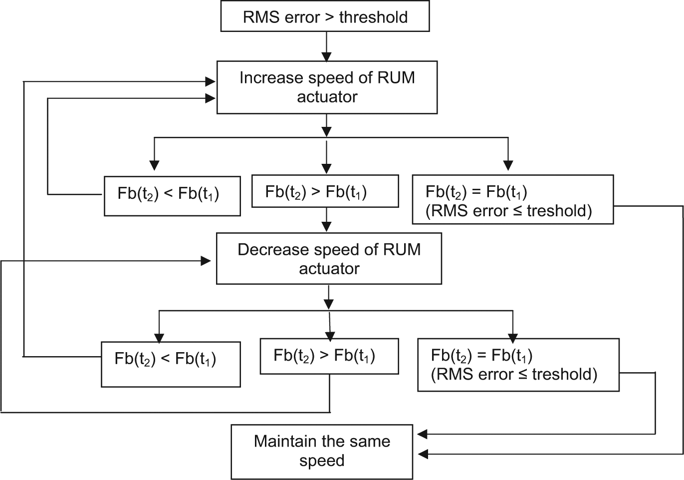
Diagram of the algorithm mode.
From Figure 3, Fb(t1) is the beat frequency at time t1, and Fb(t2) is the beat frequency at time t2. (The beat frequency is equal to the difference between the frequencies of the anti-shaker and the tremor.)
The algorithm mode was used to take care of the beating effect which occurs when two frequencies are really closed. When the beat frequency is very small, distinguishing for anti-shaker and tremor frequencies is not easy, though using spectral measurements in LabVIEW real time, the algorithm can take care of this problem.
While on this mode, the controller keeps tuning the frequency of anti-shaker to be exactly the same as of tremor frequency. Once the frequencies are the same, the anti-shaker maintains that frequency until tremor frequency changes. PID control mode can be switched on again when the two frequencies are not making beats.
Experiment setup
The experiment was set up as shown in Figure 1(b). The model of arm was made from 4 cm × 4 cm aluminum bar cut to 70 cm length. The bar is attached to a shaft at the pivot (elbow) which constraints its movement of the bar to the horizontal plane. A spiral spring is connected to the shaft at the pivot to approximate the spring constant of the human elbow.
Tremor signal was generated by an RUM actuator (12 V direct current (DC) motor, 900 r/min) on the bottom of the aluminum beam. On top of the beam, there was also another RUM actuator (same specification as the bottom actuator) mounted to use as an anti-shaker. Both RUM actuators rotate horizontally. The schematic diagram of the system is shown in Figure 4.
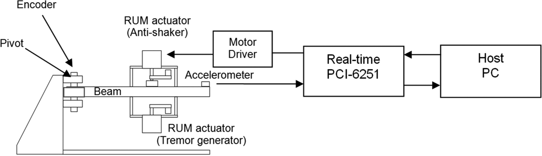
Schematics of the experimental setup.
When tremor signal was generated from LabVIEW real-time processor, the RUM actuator on the bottom started to excite the beam at tremor signal. The range of tremor frequency to generate in this experiment was 4–12 Hz. The response of the beam was measured by an accelerometer (MMA7331L), which was attached at the end of the beam, and was fed to the real-time data acquisition device (DAQ, PCI-6251). Then the signal was sent to the controller programmed by LabVIEW in a host personal computer (PC). The controller consists of PID control and a logical algorithm. The controller then produced the control signal to the response from the accelerometer and sent the signal to a DC motor driver (DC H-Bridge, SE-HB40-1) and then to the RUM actuator (anti-shaker) to counter the signal of tremor.
Results
During PID mode, the PID controller tracks the tremor frequency and feeds the signal to the anti-shaker to run at the suitable percentage of pulse-width modulation.
PID controller keeps tracking the process variable, which is the tremor frequency. In order to make the tremor vanish, the frequency of the anti-shaker and tremor has to be exactly the same. PID controller cannot handle such a task but the algorithm mode can take care of the problem as shown in Figure 5. (The frequency to track is at 6 Hz.) Other frequencies ranging from 4 to 12 Hz were also conducted but are not shown here.
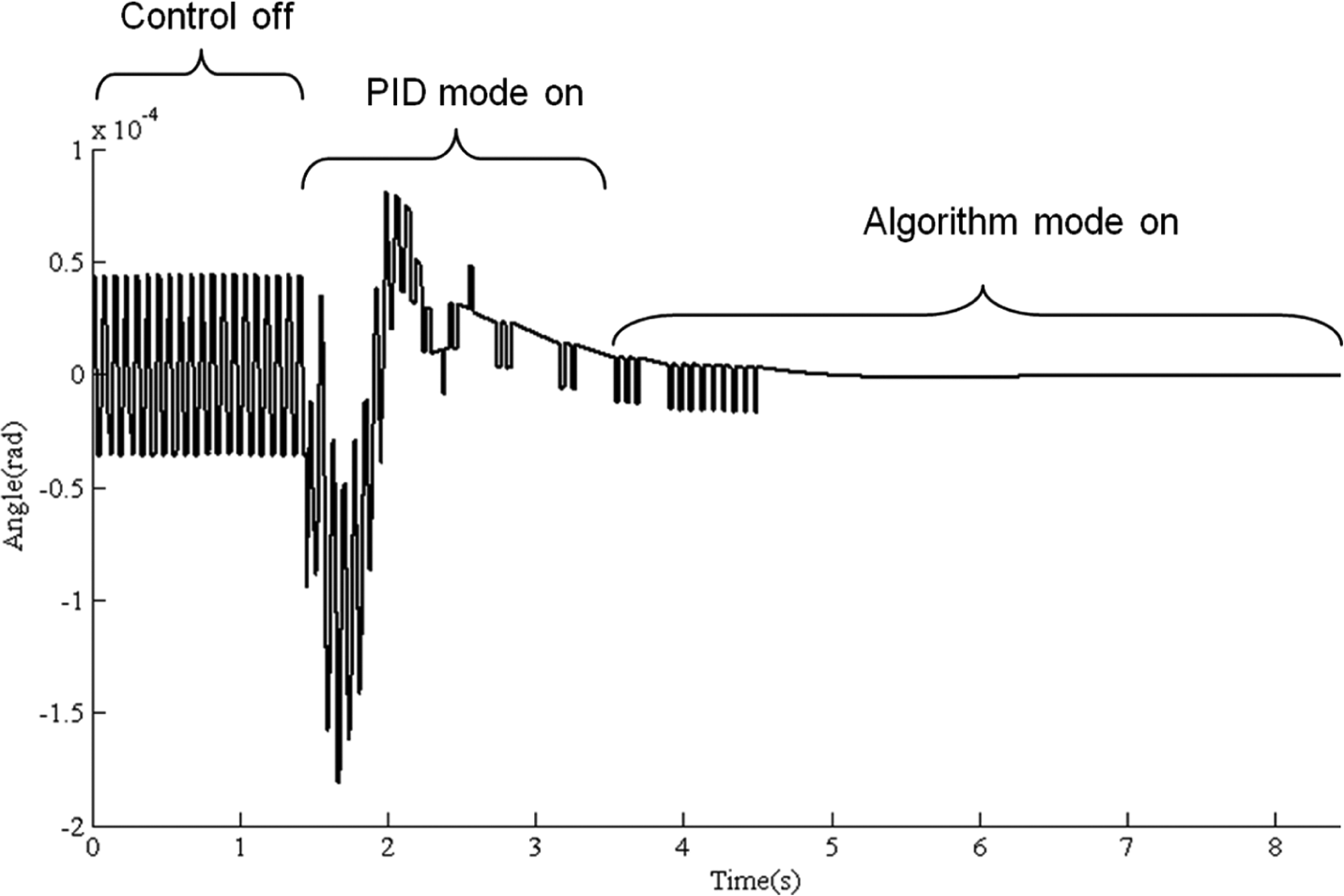
Signal from encoder at elbow, control off/on.
After control is on, the frequency of tremor decreases drastically. As the matter of fact, the beam was at the stationary stage when control is on. When the frequency of the tremor is changed, the algorithm mode will again render the system back to the same threshold. It takes about 6 s to come back to the threshold or the stationary stage.
A patient with ET would have a specific range of tremor frequency (4–12 Hz) that needs to be reduced in particular activity, mostly when his or her limb maintains position against gravity. The patient has to wait for about 6 s, as results shown in Figure 5, to let the device stabilize the tremor.
Discussion
The aim of designing the device in this research is to provide a novel method to suppress ET. Although the actual tremor signals from patients would not be clean and stationary, there are methods such as Extended Kalman Smoother 23 and voluntary movement estimation 24 which can be applied to obtain dominant signals for this device. These methods require a real-time operation, thus the system cannot have a delay over the limiting value for the real-time manner. Microcontroller such as Arduino can be used instead of LabVIEW real time. With the simple design, the device can be implemented and fabricated easily by manufacturers to provide the usefulness to orthotists thoroughly. When the clean signal is acquired, the diagram in Figure 3 can be put in action and take care of the tremor. Currently, there is no experiment with ET patients but the information used in the test was obtained from clinical sources which could be useful for the experiment with real patients in the future.
Conclusion
Nature has its way to stabilize systems. This work shows how to apply the self-balancing method. The results show that this method can reduce vibration of tremor in the order of 0.001 rad/s2. With the same amplitudes (m1 = m2 = m) and frequencies (4–12 Hz) of the anti-shaker and tremor, and without any prescribed motion in the anti-shaker (i.e. the RUM actuator must be able to spin freely round and round similar to a DC motor but not like a servo motor), the tremor can be suppressed automatically without considering of controlling or tuning the phase. This method is simple but hard to manage without real-time device because it needs almost instantaneous responses to monitor the frequencies of both anti-shaker and tremor. Nevertheless, the device will be useful for both orthotists and manufacturers.
Footnotes
Conflict of interest
The authors report no conflicts of interest. The authors alone are responsible for the content and writing of the article.
Funding
This research received no specific grant from any funding agency in the public, commercial, or not-for-profit sectors.