
Abstract
Background and aim:
Leaving open or closing the oculo-facial defect by means of a myocutaneous flap mainly depends on maxillofacial surgical considerations. For those cases that present a closed defect, the authors aim to evaluate an innovative method of ocular bulb positioning using a magnetic resonance imaging dataset.
Technique:
Following cancer removal and plastic reconstructive surgery, a Digital Imaging and Communications in Medicine format magnetic resonance imaging dataset was used to determine the volume and position of the left ocular bulb. The exact location of the prosthetic bulb was determined by mirroring this position on the affected side. Images of the eyeglasses were imported into the virtual environment, and the designs of the substructure and facial prosthesis were projected using computer-aided design/computer-aided manufacture (CAD/CAM) technology.
Discussion:
The updated method presented here enables restoration with a facial prosthesis, even when a myocutaneous flap is used to close the defect, thereby resolving the problem of ocular bulb positioning and enabling the rapid and easy design of a retention system connected to eyeglasses.
Clinical relevance
The proposed protocol aims to develop and describe a viable method for the construction of a facial prosthesis for a patient whose face had been reconstructed using a myocutaneous free flap.
Background and aim
Surgeons can choose to close or leave open large facial defects caused by cancer ablation. Closure is sometimes disadvantageous for aesthetic reasons, especially when a myocutaneous flap is used. Leaving the defect open provides the ability to control orbital malignancy and the opportunity to construct a silicone prosthesis for rehabilitation, but entails disadvantages such as respiratory infection, cold sensation, hyperstimulation of cranial nerves, visual compromise, and dramatic facial disfigurement with psychological and social impacts. 1 In such cases, the main problems faced by an anaplastologist–prosthetist in the manufacturing of orbital epitheses are related to the retention and to the orbital positioning. The retention may be committed to an adhesive or an implant-supported prosthesis,2,3 and the orbital positioning may be obtained using the wax-up straight on the patient face. 4 The use of osseointegrated implants for the retention of the prosthesis has been always considered the best option to give stability to the prosthetic rehabilitation, with respect to the adhesive prosthesis that presents all the disadvantages of using a skin glue. A disadvantage of the implant-retained prosthesis is the need to leave an open defect after ablative cancer surgery. Advances in laser-scanning, computer-aided design/computer-aided manufacture (CAD/CAM), and rapid-prototyping (RP) technologies for the construction of facial prostheses have been made in the past decade, and studies have confirmed the significant advantages of these modalities and those of digital techniques, especially in cases like the one presented here, in which a closure of the defect was autonomously planned by the surgeon without the consultation of the prosthodontist.2,3,5–10
This pilot study was conducted to find a solution for a patient who had undergone surgical facial reconstruction with a soft-tissue transfer (rectus abdominis free flap) after cancer removal, with no prosthetic treatment planning with the maxillofacial prosthodontist. Free-tissue transfers, such as those employing latissimus dorsi 2 or rectus abdominis3,4 free flaps, fill the orbital defect, provide healthy tissue to irradiated areas, and avoid much of the morbidity associated with the use of local flaps. Disadvantages of the use of free flaps include donor site morbidity, the potential need for subsequent debulking, and skin color mismatches. In the case described here, we attempted to restore the secondary defect, which was covered by a myocutaneous flap. Although restoration with a silicone prosthesis is traditionally believed to be difficult in such situations, a CAD/CAM protocol was developed to account for the mobility of the flap and the patient’s aesthetic and social demands, and to provide support for the prosthesis. The aim of this pilot study was to develop and describe a viable method for the construction of a facial prosthesis for a patient whose face had been reconstructed using a myocutaneous free flap. Informed consent once obtained from the patient and ethical approval was sought from the S. Orsola University Hospital.
Technique
A Digital Imaging and Communications in Medicine (DICOM)-format magnetic resonance imaging (MRI) dataset was used instead of a computed tomographic dataset to better detect all soft tissues involved in the defect and determine the position of the ocular bulb. Laser scanning of the face was performed to obtain an accurate representation of the skin surface. The defect was considered to be the ideal center of a hexagon and scanned from six angles using a three-dimensional desktop laser scanner (NextEngine, Santa Monica, CA, USA) to detect all undercuts. The class 1M laser beam allowed for safe scanning of the eye. Under the maxillofacial prosthodontist’s supervision, the CAD technician elaborated the solid-to-layer (STL) file of the face using the ClayTools system (Freeform Modeling Plus software and Phantom Desktop Haptic device; Sensable, Wilmington, MA, USA). The elaborated STL file was then integrated into the DICOM-format MRI data, and the design of the prosthesis was projected to cover the defect from the frontal and temporal deficiency inferiorly to the midfacial region and, medially, to the lateral wall of the nasal pyramid. Then, a laser scan of the patient’s eyeglasses was taken, and the glasses were virtually positioned on the glabella and ears. The ocular bulb was manufactured by a specialized technician and laser scanned to integrate its volume into the virtual environment. The position of the contralateral ocular bulb was used to center the position of the pupil (Figure 1). The entire virtual design of the prosthetic ocular bulb position was developed on the basis of MRI dataset. During the MRI examination, the patient was asked to look a point in front of him so taking the ocular bulbs symmetrically centered: the mirrored native ocular bulb was used to guide the final position of the prosthetic bulb. To obtain this, the resin ocular bulb was scanned and a STL file was obtained. Then, it was superimposed to the mirrored virtual but native ocular bulb previously repositioned by using MRI data. Also the pupil was set in the exact specular position of the healthy eye. To exactly reposition the prosthetic pupil of the resin bulb according to the native mirrored one, a small provisional wax excrescence had been made in the prosthetic bulb before scanning in correspondence to the pupil. The excrescence allowed to superimpose the prosthetic pupil to the native one (visible in the MRI) and allowed to direct correctly the gaze. Once the correct position of the prosthetic eye was determined, a substructure to secure in that position the prosthetic bulb and to connect the prosthesis to the eyeglasses was projected with two arms: one arm was projected above the right lens and the other was positioned medially on the lateral shaft to allow eyeglass removal away from the facial prosthesis (Figure 2).
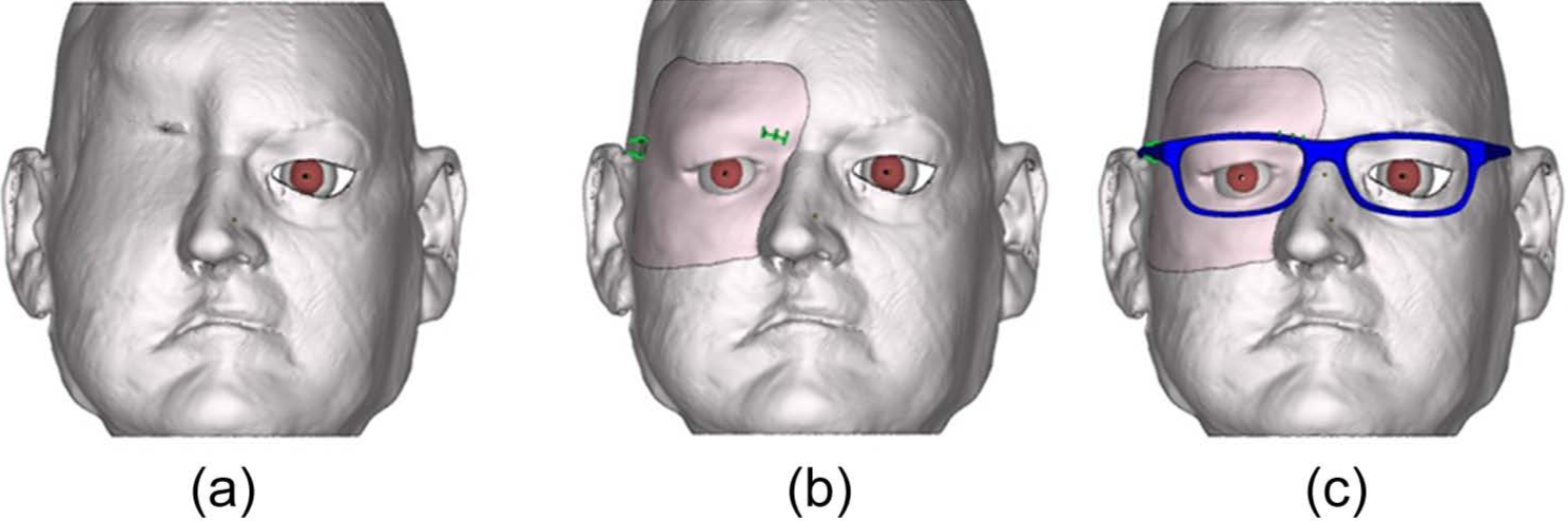
Magnetic resonance images used to determine (a and b) the ocular bulb position through (c) mirroring on the prosthesis.
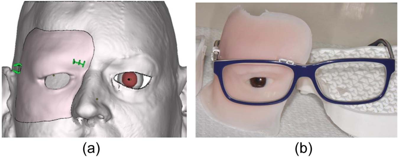
(a) The retentive system for the eyeglasses (green/gray clasps) and (b) the facial prosthesis before coloring and eyelid positioning.
Following completion of the CAD process, a rapid-prototyped polyamide resin copy was printed and checked on the patient to detect incongruent margins and ensure that the eyeglasses were positioned correctly in relation to the face and prosthesis. The actual position of the ocular bulb was also controlled in this step. Before mold prototyping, an area 1.5 cm from the margin of the prosthesis copy was corrected to be progressively under-leveled (up to 5 mm) with respect to the real prosthesis, and the thickness of the prosthesis was minimized to provide a flexible silicone margin that would remain adhered to the skin during cheek movement. The retentive substructure was designed with clasps for the eyeglasses and precise support for the ocular bulb. This support facilitated anchoring of the bulb because its retentions allowed precise positioning of the eye into the prosthesis. To avoid interfering with the retentive clasps during silicone processing, two small portions of the eyeglass structure were reproduced and inserted into the embrasures to prevent silicone flow. The entire substructure was printed using a polyamide material.
Macroporosity was projected on the back of the prosthesis to reduce its weight as much as possible. Half-spheres with diameters of 6 mm were positioned on all rear prosthesis portions with widths exceeding 5 mm to reducing the risk of aesthetic impairment.
The final mold was projected to ensure secure and precise ocular bulb and substructure positioning during silicone processing. The mold was prepared for laser sintering with the Freeform Modeling Plus software and manufactured directly using the RP machine (Phantom Desktop Haptic device, ClayTools system; Sensable). The working principle was based on selective laser sintering of polyamide powder. Finally, the silicone was processed and extrinsic coloring was applied before delivery of the oculo-facial prosthesis. The conventional silicone (VST-50F; Factor II, Inc., Lakeside, AZ, USA) processing procedures were completed to obtain the definitive prosthesis, and intrinsic colors (Intrinsic, Factor II, Inc.) were used before silicone processing. No separating agent was used on the RP mold and substructure prior to filling with silicone. Extrinsic colors (Extrinsic, Factor II, Inc.) were applied, and silicone adhesive (A-564; Factor II, Inc.) was used as a sealant. Finally, matting dispersion liquid (TS-564; Factor II, Inc.) was applied to provide a matte appearance to the prosthesis.
Discussion
Facial prosthesis manufacture is challenging for the clinician in terms of anaplastology and stabilization the provisional prosthesis without implants. Laser scanning, CAD/CAM, and RP technologies have simplified such procedures because the entire process of provisional oculo-facial prosthesis construction can be automated. Compared with previously documented automated procedures, the present protocol introduces several innovations.
First, this updated method enables the use of a facial prosthesis in patients with facial defects that have been closed using myocutaneous vascularized grafts. This option may be extremely important for the surgeon when considering how to restore a postablation surgical defect. In the past, closed facial defects were potentially problematic for prosthodontists due to the difficulty of anchoring the prosthesis to soft and mobile tissue, such as a myocutaneous flap. Moreover, the use of a DICOM-format MRI dataset enabled exact reproduction of the contralateral eye bulb and pupil positions on the prosthesis.
The second innovation of this protocol is the use of a method to produce a very thin and compressive silicone prosthesis that is adaptable to natural cheek movements. This feature is novel because a previous contraindication for facial defect closure was the inability to precisely position a prosthesis on the soft tissue of a graft, leading to a gap between the skin and prosthesis. Our technique involves progressive skin-plane reduction on the virtual patient’s face, corresponding to the prosthesis margin. Moreover, the thickness of the prosthesis was minimized (≤1 mm) in a 1.5-cm area along the margin and progressively increased to full thickness. This approach yielded a thin silicone flap at the margin of the prosthesis that maintained compression, even on a mobile surface.
The third innovation was the creation of a substructure that allowed anchoring of the prosthesis to the eyeglasses without the need for a complex connection system; two retentive arms were used to engage the lateral shaft and the upper frontal eyeglass contour. The substructure was produced entirely using RP of a polyamide material, which guaranteed that the engaging arms had sufficient elasticity when the prosthesis was connected to the eyeglasses. Moreover, this connection system enabled removal of the eyeglasses away from the prosthesis, allowing the patient to use skin glue or the eyeglasses to support the prosthesis. The substructure was projected to firmly retain the ocular bulb in the exact virtually planned position (Figures 3 and 4).
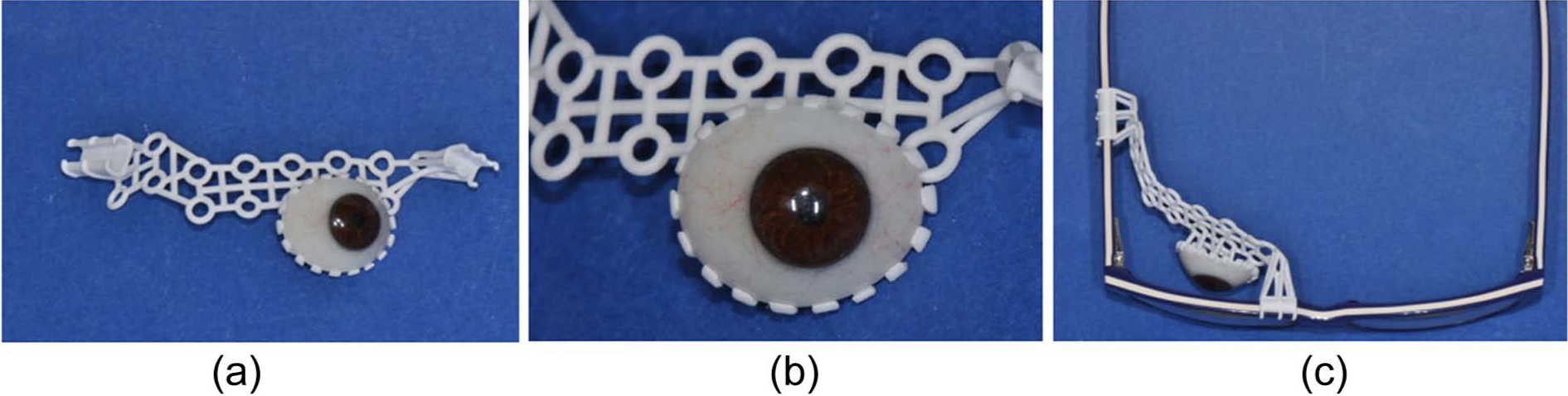
Three-dimensional printing of the substructure: (a) complete volume, (b) retention for the bulb, and (c) clasps for the eyeglasses.
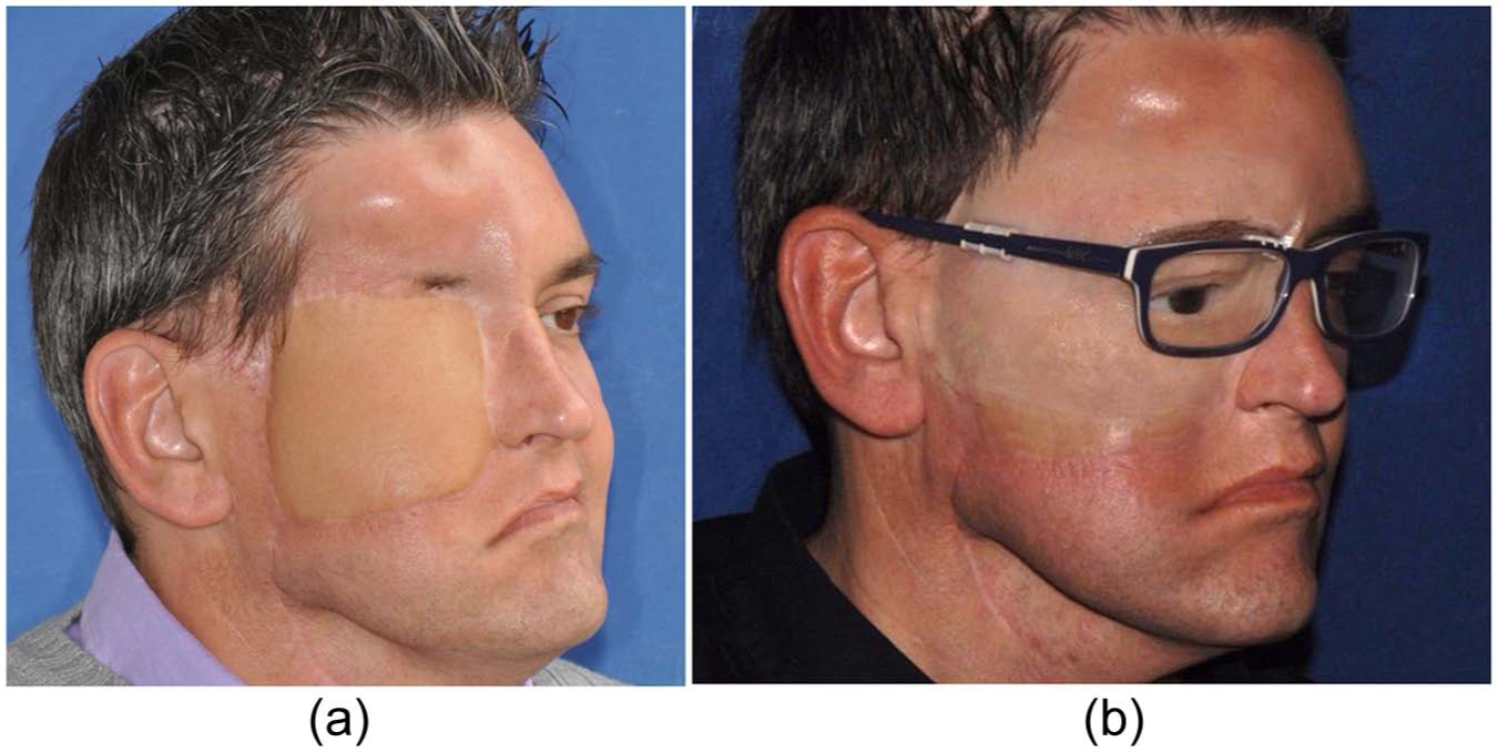
The final result: (a) before and (b) after.
One more advantage of this technique is the method of fixation of the facial prosthesis. Conventional protocols2–4 proposed two main ways to stabilize wide facial epitheses: by maintaining the defect open to utilize all undercuts and to anchor the prosthesis without craniofacial implants but using skin glue, and by inserting craniofacial implants to support the epithesis. Until now, the eyeglasses were not a useful method to support the facial prosthesis: constructing a retentive substructure was complex in terms of eyeglasses connection and volumetric manufacturing. CAD/CAM new technologies allowed simplifying the design and the printing of the substructure, adapting it to the prosthetic volume and to the eyeglasses size that the patient has chosen.
The absence of problems with glue removal is a further benefit from this technique. The eyeglasses completely support and maintain the prosthesis in the correct position, making the patient free of using the skin glue and consequently improving the longevity of the prosthesis.
The limitations of this technique may be related to the limited availability of a CAD technician for servicing and of a RP printer. Also, closing the oculo-facial defect by means of a myocutaneous flap may be a prosthetic limitation, due to the difficulty to adapt a flexible margin of the prosthesis to the mobile surface of the flap during functional movements of the cheek.
The method presented here allows the maxillofacial prosthodontist to obtain a facial prosthesis for those patients who underwent facial reconstructive surgery with a myocutaneous free flap. It may be used as a definitive epithesis whenever no further surgery is programmed, but if a plastic surgery is expected, it may be used as an immediate–temporary prosthesis. The cost of the entire procedure is € 700 with the CAD/CAM elaboration.
Key points
The following key points may be highlighted:
The flexible margin allowed dynamic adaptation to cheek movements during functional and emotional expression. This typical feature of the prosthesis allowed the use of a myocutaneous flap to cover the defect and avoided all clinical problems related to an open midfacial defect.
The use of a DICOM-format MRI dataset enabled detection of the position of the contralateral eye bulb, simplifying the positioning of the pupil.
The retention system simplified the connection between the eyeglasses and the prosthesis substructure, eliminating the need for a more complex connection arrangement 9 and facilitating disconnection and reconnection by the patient during home maintenance or eyeglass servicing.
The inclusion of retention clasps for the eyeglasses in the substructure simplified the connection and enabled the development of a prosthetic system that could be used with or without the eyeglasses. Moreover, the substructure support for the ocular bulb retained the prosthetic eye in a secure and stable position during silicone processing.
The prosthesis weight was reduced by 75 g through the use of a half-sphere design with volume voids on the back of the prosthesis, minimizing skin-prosthesis contact.
Footnotes
Acknowledgements
The authors thank Andrea Sandi, (SINTAC, Rovereto, Italy) for his valuable work in CAD and in the rapid prototyping of the mold and substructure.
Conflict of interest
The authors declare that there is no conflict of interest.
Funding
This research received no specific grant from any funding agency in the public, commercial, or not-for-profit sectors.