
Abstract
Background:
The investigation draws from the fundamentals of the mechanical behaviour of titanium grade 2 to the design and fabrication of facial implants by means of single point incremental forming.
Objectives:
To provide knowledge on the capabilities and limitations of a new manufacturing technology to fabricate low-cost, patient-specific medical implants.
Study design:
Rapid fabrication of a simplified model of a facial implant.
Methods:
Circle grid analysis and its graphical representation in the fracture forming limit diagram combined with finite element modelling are utilized to identify the failure limits and to assist the overall design of the facial implants.
Results:
Fabrication of facial implants without and with failure by cracking due to excessive thinning of the sheet from where the implant is to be cut.
Conclusions:
Identification of the major operative parameters that influence fabrication of sound facial implants by means of single point incremental forming.
Clinical relevance
Reduce the gap between production engineers and the medical community by presenting a state-of-the-art manufacturing technology to produce low-cost, patient-specific medical implants.
Background
Facial implant surgery helps restoring normal appearance to patients who were born without certain facial features, to patients who have lost their facial features as a consequence of accidents or diseases or to patients who simply want to improve their appearance.
In recent years, this area of medicine experienced an increasing interdisciplinarity between the medical and the production engineering communities. Production engineers can play a key role in transferring state-of-the-art knowledge on manufacturing into innovative, cost-efficient solutions for facial implants that precisely match the needs of patients because conventional technologies such as casting, stamping and hydroforming are inadequate to provide very short development and production lead times of low-volume customized implants. Casting would even raise technical difficulties due to the contraction of titanium (the most widely used material for medical implants, due to its biocompatibility properties) from melting to room temperature, to the extreme reactivity of titanium to the gases of the atmosphere at high temperatures and to the difficulty in attaining complex geometries with very thin walls that are typical of facial implants.
Resorting to other conventional fabrication processes such as machining avoids processing titanium under warm or hot conditions and enables the production of thin-walled customized implants with geometric configurations, tolerances and surface finishes that are unobtainable by any other processes. However, because machining generates the final shape of the implants from a solid billet by removing excess material in the form of chips, the fabrication inevitably results in becoming time-consuming and costly due to the high value of the titanium lost in scrap.
In view of the above limitations and specific needs of conventional manufacturing processes, there are situations nowadays where medical implants (e.g. cranial plates) are still shaped manually by plastic surgeons in the operating room. This is seen as highly unfavourable to patients because manual forming increases time in surgery and the resulting implants may encompass aesthetic problems and functional fit difficulties with the surrounding bone area.
Recent developments in incremental sheet forming (ISF) applied to flexible small-batch production of industrial engineering parts has been followed with great interest by those engaged in the fabrication of medical implants due to the possibility of getting access to innovative, cost-effective manufacturing processes that can easily solve patient-specific needs. Comprehensive state-of-the-art reviews in the research and application of the ISF technology to the production of industrial parts can be found in Jeswiet et al. 1 and Echrif and Hrairi. 2
Figure 1(a) presents a scheme of a variant of ISF called single point increment forming (SPIF) showing the rig, the pressure pad, the backing plate and the forming tool. The pressure pad holds the sheet blank against the backing plate and prevents drawing-in during SPIF. The backing plate supports the blank, and its opening contour defines the working area of the forming tool. The forming tool has a hemispherical end and is utilized to locally and progressively shape the blank into an implant along a predefined tool path. Besides being a dieless, low-cost manufacturing process that is capable of withstanding very short life cycles and reducing lead times in development and production, SPIF is also known to provide higher formability limits than those commonly found in conventional sheet metal forming processes such as stamping, stretch forming and deep drawing, among others. 3
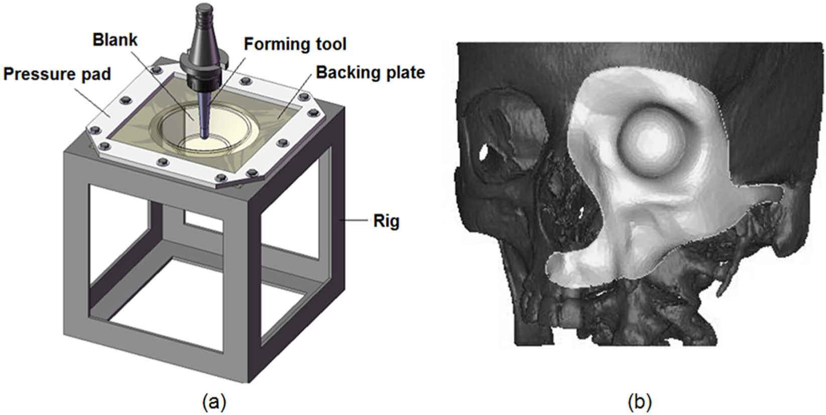
Single point incremental forming (SPIF): (a) schematic representation of the process and (b) details of the facial implant that was utilized for setting up a simplified model to be produced by SPIF in a medical image obtained from magnetic resonance imaging (MRI).
The first research publications on SPIF of medical implants were by Ambrogio et al., 4 who fabricated an ankle support in deep drawing quality steel, and Duflou et al., 5 who produced an aluminium cranial plate utilized in reconstructive skull surgery. Both articles focused on describing the customizable process chain capabilities of SPIF for producing patient-specific implants. Eksteen and Van der Merwe 6 recently returned to the subject by documenting the design and development of titanium arthroplasty implants. Oleksik et al. 7 presented an experimental study on the surface quality of medical implants used for the partial resurfacing of the femoral condylar surface of the knee obtained by SPIF of Ti-6Al-4V sheets. More recently, Duflou et al. 8 discussed the challenges associated with the manufacture of cranio-facial implants with extreme forming angles using aluminium, stainless steel and titanium sheets.
In contrast to the above-mentioned exploratory test cases aimed at showing the potential of SPIF for producing different types of patient-specific implants made from different materials, there has been a lack of engagement in performing a systematic investigation on the formability limits and the maximum drawing angles of titanium in SPIF. This is a critical gap in knowledge that needs to be addressed in order to successfully design and fabricate medical implants (such as facial implants) with complex geometrical shapes. By providing the above-mentioned information to the medical community, it is also expected that surgeons become interested in exploring the potential of this new manufacturing technology and understanding its capabilities and limitations for the production of low-cost, patient-specific implants.
This article deals with the above-mentioned matters and is divided broadly into two different parts. The first part presents the mechanical characterization of titanium grade 2 and its failure limits by necking and fracture obtained by means of independent sheet metal formability tests and benchmark SPIF tests on truncated conical and pyramidal parts. Topics to be addressed comprise determination of the forming limit curve (FLC) and fracture forming limit line (FFL) by means of circle grid analysis, determination of the maximum drawing angle at the onset of cracking and characterization of the likely mode of failure in SPIF.
The second part of the article focuses on the fabrication of a simplified model of the facial implant shown in Figure 1(b), with the objective of demonstrating how circle grid analysis combined with the fracture forming limit diagram can be utilized to successfully re-engineer the fabrication of a facial implant. To be more specific, the article shows how the overall level of in-plane strains and drawing angles can be controlled in order to obtain a sound facial implant produced by SPIF.
Methods
Mechanical characterization and circle grid analysis
The simplified model of the facial implant produced by SPIF was made from unalloyed titanium grade 2 sheets with maximum oxygen concentration of 0.25% and maximum concentration of impurities of C (0.1%), Fe (0.3%), H (0.015%) and N (0.03%). The mechanical properties of the material were determined by means of tensile tests (performed in an Instron 4507 testing machine) in specimens cut from the supplied sheets at 0°, 45° and 90° with respect to the rolling direction.
The formability limits at necking (FLC) and fracture (FFL) in the principal strain space (forming limit diagram) were determined by means of tensile tests, hydraulic bulge tests and benchmark SPIF tests performed in truncated conical and pyramidal parts. The tensile tests were performed in a universal testing machine, and the hydraulic bulge tests were performed in a universal sheet testing machine (Erichsen 145/60) using biaxial circular (100 mm) and elliptical (100/63 mm) tooling sets (Figure 2(a)). The benchmark SPIF tests were carried out in a computerized numerical control (CNC) machining centre equipped with an experimental apparatus similar to that schematically illustrated in Figure 1(a) and were characterized by a drawing angle ψ increasing with the depth (Figure 3).
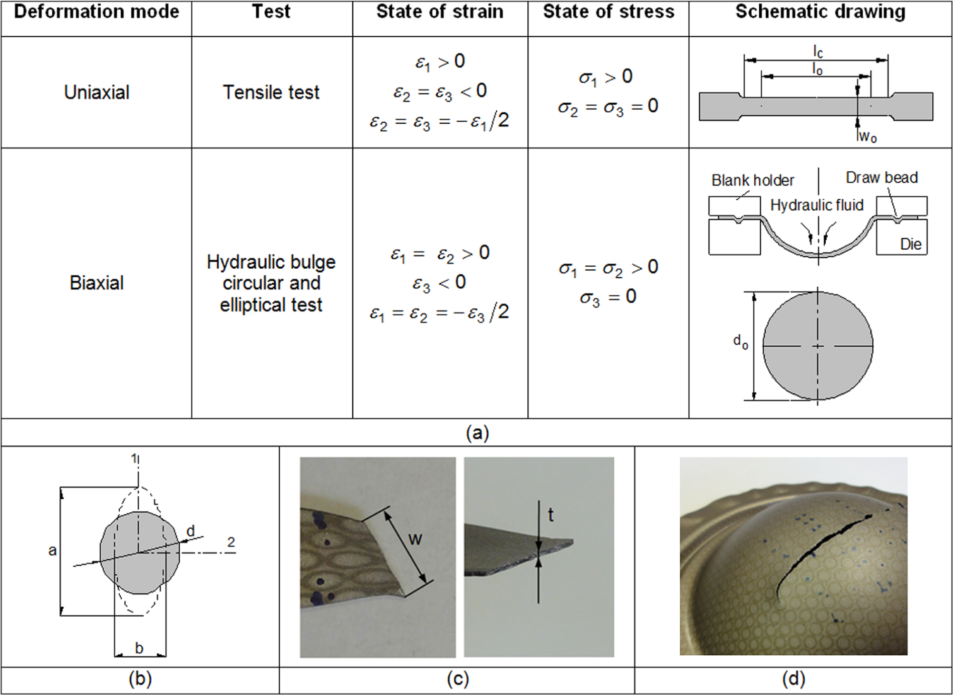
Formability tests and measuring procedures that were utilized for determining the FLC and FFL of titanium grade 2 sheets: (a) schematic drawing of the tensile of hydraulic bulge tests, (b) major and minor axes of the ellipses that were utilized for determining the principal logarithmic strains, (c) procedure for obtaining the gauge length strains at the onset of fracture in a tensile test and (d) circles distorted into ellipses after a hydraulic bulge circular test.
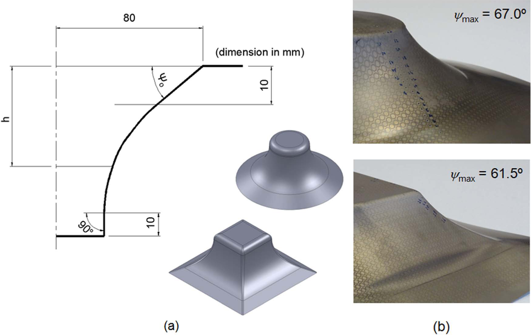
Benchmark SPIF tests performed on truncated conical and pyramidal shapes: (a) geometrical details of the tool path showing the initial drawing angle ψ0 and the progressive increase of the drawing angle ψ(h) with the depth and (b) photographs showing details of the truncated conical and pyramidal shapes with indication of the maximum drawing angles ψmax.
The principal strains (ε1, ε2) on the sheet surface were determined by circle grid analysis and involved electrochemical etching of a grid of overlapping circles with 2.5 mm initial diameter on the surface of the specimens before forming and measuring the major and minor axes of the ellipses that resulted from the plastic deformation of the circles during the formability and benchmark SPIF tests (the procedure is illustrated in Figure 2(b))
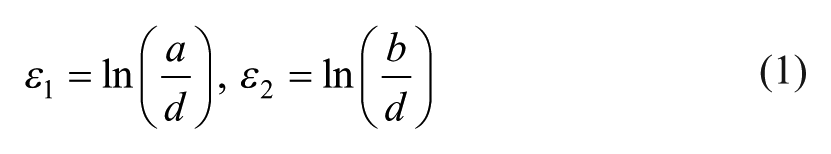
where the symbol d represents the original diameter of the circles and the symbols a and b denote the major and minor axis of the ellipses.
The FLC was obtained by taking the principal strains (ε1, ε2) at failure from grid elements placed just outside the neck (i.e. adjacent to region of intense localization) in both tensile and hydraulic bulge tests since they represent the condition of the uniformly thinned sheet just before necking occurs. In practical terms, authors made use of Zurich No. 5 experimental procedure for determining the strains at necking by means of the strains retrieved from measurements in adjacent deformed circles along a direction perpendicular to the crack. 9
The FFL was determined by measuring the thickness of the specimens before and after fracture at several places along the crack (in order to obtain the ‘gauge length’ strains) in tensile, hydraulic bulge and benchmark SPIF tests. In case of tensile tests, the gauge strain in the width direction was obtained as illustrated in Figure 2(c) and required utilization of the circles to obtain the initial and deformed reference lengths. The third fracture strain component, in the plane of the sheet with direction perpendicular to the crack, was determined by volume constancy knowing the two other strains. A similar procedure was utilized for determining the ‘gauge length’ strains resulting from the circular and elliptical hydraulic bulge tests (Figure 2(d)).
Fabrication of facial implants by SPIF
The fabrication of the facial implant by SPIF was done by making use of the simplified model shown in Figure 4. The main reason for utilizing a simplified model instead of the actual facial implant was to avoid multistage tool path strategies at the orbital cavity and to focus the aims and scope of the study on the interaction between implant design and fundamental SPIF issues related to formability limits and maximum drawing angles.
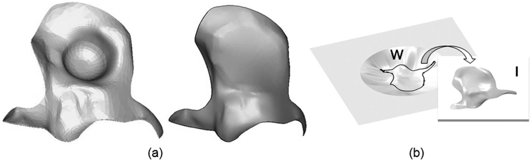
Simplified model of the facial implant produced by SPIF: (a) geometry of the actual and simplified model of the facial implant and (b) schematic representation of the deformed blank produced by SPIF, from where the facial implant is to be removed.
The experiments made use of titanium grade 2 blanks with 250 mm × 250 mm × 0.7 mm that were electrochemically etched with grids of circles of 2.5 mm in diameter in order to allow in-plane strains to be measured from the deformed ellipses by means of circle grid analysis described in the previous section. The deformed blanks were divided into two different regions: (1) the region of interest (labelled as ‘I’ in Figure 4(b)) from where the facial implant is to be removed and (2) the surrounding walls (labelled as ‘W’ in Figure 4(b)) that are needed for connecting the facial implant to the upper clamped surface of the blank. The profiles of these regions were modelled by means of loft surfaces in a computer aided design (CAD) system. The resulting CAD geometry of the facial implant with the additional surrounding walls was subsequently transferred into a computer aided manufacturing (CAM) software for setting up the operating conditions and defining the forming tool path.
The experiments were performed with helical tool paths characterized by a step size per revolution equal to 0.2 mm (downward feed) and a feed rate equal to 1000 mm/min. The tool path accounted for 2 mm gap with the inner contour of the backing plate in order to avoid excessive bending of the blank and to prevent collision of the forming tool against the rig.
The forming tool had a hemispherical tip end with 12 mm diameter in order to ensure a good reproducibility of the implant geometry and was made from cold working 120WV4-DIN tool steel, hardened and tempered to 60 HRC. The rotation of the forming tool was set free during the experiments, and friction between the tool and deformed sheet was reduced by means of ceramic grease WEICON ASW 040P.
After being formed, the implant was removed from the deformed blank by cutting its perimeter with a 5-mm diameter cylindrical milling tool in the same CNC milling machine where the blank was shaped by SPIF.
Finite element modelling
The fabrication of the simplified model of the facial implant by SPIF was simulated by means of the commercial finite element computer program ABAQUS. The lack of symmetry in the deformed blank and tooling required the utilization of a complete three-dimensional finite element model with a large number of degrees of freedom (approximately 60,000). The simulation was performed with a dynamic explicit finite element formulation that is represented by the following matrix set of nonlinear equations
which express the dynamic equilibrium condition at the instant of time ‘t’. The symbol
The choice of a dynamic explicit formulation is justified by the fact that it does not present convergence problems and can easily take into consideration the practical non-linearities in the geometry and material properties as well as the contact changes typical of SPIF, to provide accurate predictions of displacements, strains and stresses, among other variables. The dynamic explicit formulations also present advantages regarding the overall computation time (central processing unit (CPU) time) because it ensures a linear variation with the number of degrees of freedom, whereas in quasi-static implicit formulations, CPU time depends more than linearly (in case of iterative solvers) and up to quadratically (in case of direct solvers) on the number of degrees of freedom. Further information on finite element formulations applied to metal forming processes is available elsewhere. 10
The blank was discretized by means of a layer of 8-noded hexahedral elements and computation made use of Hill’s 48 anisotropic yield criterion, 11 a selective reduced integration method (C3D8R from ABAQUS library) and an arbitrary Lagrangian–Eulerian (ALE) procedure. The forming tool with a hemispherical tip end was modelled as a rigid analytical surface, and the backing plate was discretized by means of 3-noded rigid elements (R3D3 from the ABAQUS element library). The tool path of the forming tool was retrieved from the CAM program and uploaded into the finite element model by means of an external user subroutine VUAMP. The frictional conditions between the tool and the blank were characterized by means of the Amonton–Coulomb law (µ=0.01).
Figure 5 presents the finite element model of a facial implant by SPIF at an intermediate stage of the process.
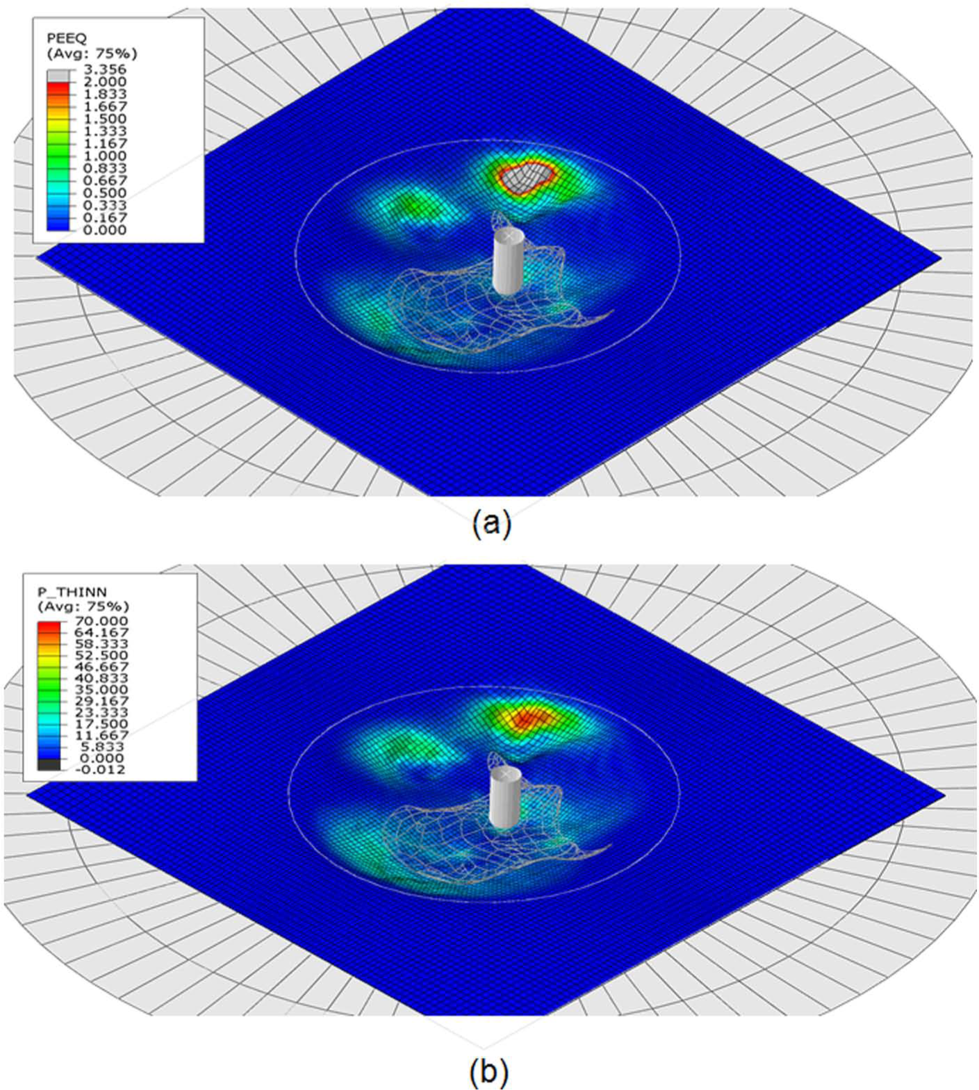
Finite element simulation of the unsuccessful attempt to obtain a simplified model of the facial implant produced by SPIF: (a) computed distribution of the effective strain and (b) computed distribution of sheet thinning (values in percentage).
Results
Stress–strain curve
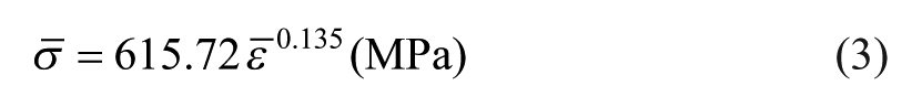
The average values of the modulus of elasticity E, yield strength σ Y , ultimate tensile strength σ UTS , anisotropy coefficient R and elongation at break A obtained from the tensile tests are summarized in Table 1. The average stress–strain curve derived from the tensile tests was approximated by the following Ludwik–Hollomon equation
Mechanical properties of the titanium grade 2 sheets obtained from tensile tests.
where
Fracture forming limit diagram
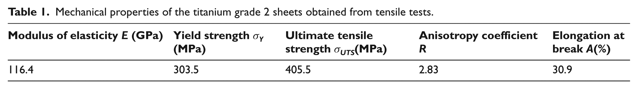
The FLC and FFL resulting from the formability tests are plotted in Figure 6. The FLC intersects the major strain axis at a point equivalent to the strain hardening exponent (n = 0.135) in equation (3) and the FFL was approximated by means of a straight line falling from left to right
Forming limit curve (FLC), fracture forming limit line (FFL) and iso-thickness reduction line (in percentage) of titanium grade 2 in the principal strain space (forming limit diagram). The solid markers refer to failure by fracture.
The FFL is bounded by grey areas corresponding to an interval of 10% due to the experimental uncertainty in its determination, and its slope (−0.812) is in good agreement with the condition of constant thickness strain at fracture due to Atkins 12
where rmax≅ 37.7% is the reduction in sheet thickness at the onset of failure by fracture under plane strain conditions (refer to the dashed upper grey line in Figure 6). The corresponding maximum drawing angles ψmax for the benchmark truncated conical and pyramidal shapes are given in Figure 3(b).
The small distance from neck formation (FLC) to collapse by fracture (FFL), corresponding to a reduction in sheet thicknesses from 12% to approximately 38% (refer to the dashed grey lines in Figure 6), indicates that titanium grade 2 has poor workability and signs of interaction between instability and fracture near biaxial tension. The poor workability of titanium grade 2 is attributed to its hexagonal close-packed crystal structure at cold working temperature, and the interaction between instability and fracture is consistent with the concept of local necking and ductile fracture being competitive modes of failure, which is comprehensively discussed by Embury and Duncan. 13
Fabrication of a simplified model of the facial implant
The first attempts to fabricate the simplified model of the facial implant by SPIF resulted in failure by cracking that was triggered at the surrounding walls (labelled as ‘W’ in Figure 4(b)) and progressed towards the region of the deformed blank where the implant was located (refer to the photographs in Figure 7). The morphology and propagation direction of the cracks in conjunction with the absence of changes in the strain loading paths after crossing the FLC allow concluding that plastic deformation takes place by uniform thinning (without necking) after exceeding the maximum load-carrying capacity due to the meridional stresses σϕ acting on the walls.
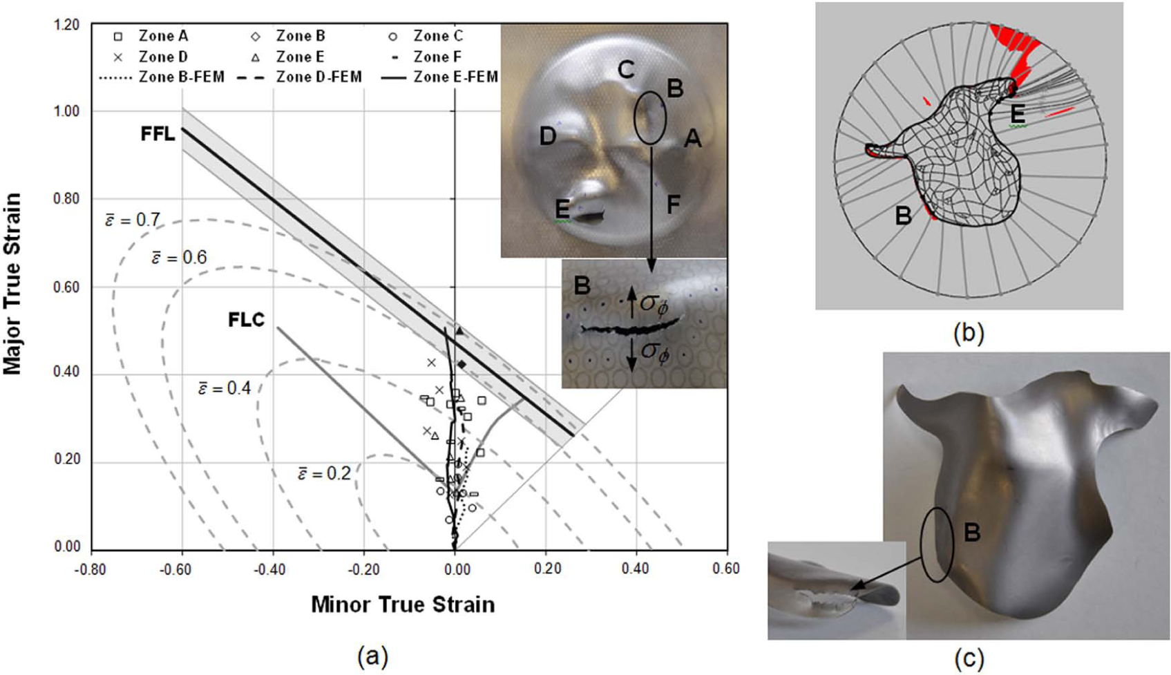
Unsuccessful attempt to obtain a simplified model of the facial implant produced by SPIF: (a) forming limit diagram with identification of the zones A–F of the deformed blank (dashed grey lines refer to the iso-effective strain contours), (b) schematic representation of the deformed blank with indication of the regions B and E where the drawing angles are larger than the maximum admissible drawing angle ψmax and (c) photograph of the implant with indication of zone B where cracking occurred.
As will be discussed in the following section of the article, combination of the fracture forming limit diagrams with the maximum admissible drawing angle ψmax allowed authors to redesign the surrounding walls that connect the implant to the rest of the workpiece in order to produce sound facial implants.
Discussion
The results from the first attempts to produce the simplified model of the facial implant by SPIF are better understood by analysing the strain values of selected grid points that are located in the zones A–F of the deformed blank (Figure 7(a)). These zones belong to the aforementioned two different regions of the deformed blank (labelled as ‘I’ and ‘W’ in Figure 4(b)) and are clearly identified in the photographs enclosed in Figure 7.
As seen in Figure 7(a), the experimental values of strain obtained by means of circle grid analysis are mainly located along plane strain loading conditions. The grid points in zones B and E, where the drawing angles of the deformed blank are larger than the maximum admissible drawing angle ψmax (Figure 7(b)), attained strain values within the grey areas of FFL uncertainty and, therefore, gave rise to failure by cracking (Figure 7(c)).
The finite element predictions corroborate the experimental measurements, namely, in providing strain values close to plane strain loading conditions and in intersecting the FFL in case of grid point E (refer Figure 7(a)). Three-dimensional plots of the finite element estimates of effective strain and thinning that are included in Figure 5 allowed authors to identify B and E as the critical regions of the deformed blank where cracks are triggered and subsequently progress into the region where the implant is located. This result is also in good agreement with the experimental observations and demonstrates the potential of finite elements for assisting the design and fabrication of patient-specific facial implants produced by SPIF.
As shown in Figure 8, by redesigning the facial implant in order to smooth the drawing angles of the surrounding walls, it was possible to avoid excessive thinning in regions B and E of the deformed blank and implant. In practical terms, this was accomplished by repositioning the implant so as to move it closer to the surface that represents the initial blank, by centring the implant within the inner contour of the backing plate and by rotating the implant in order to minimize the wall angles.
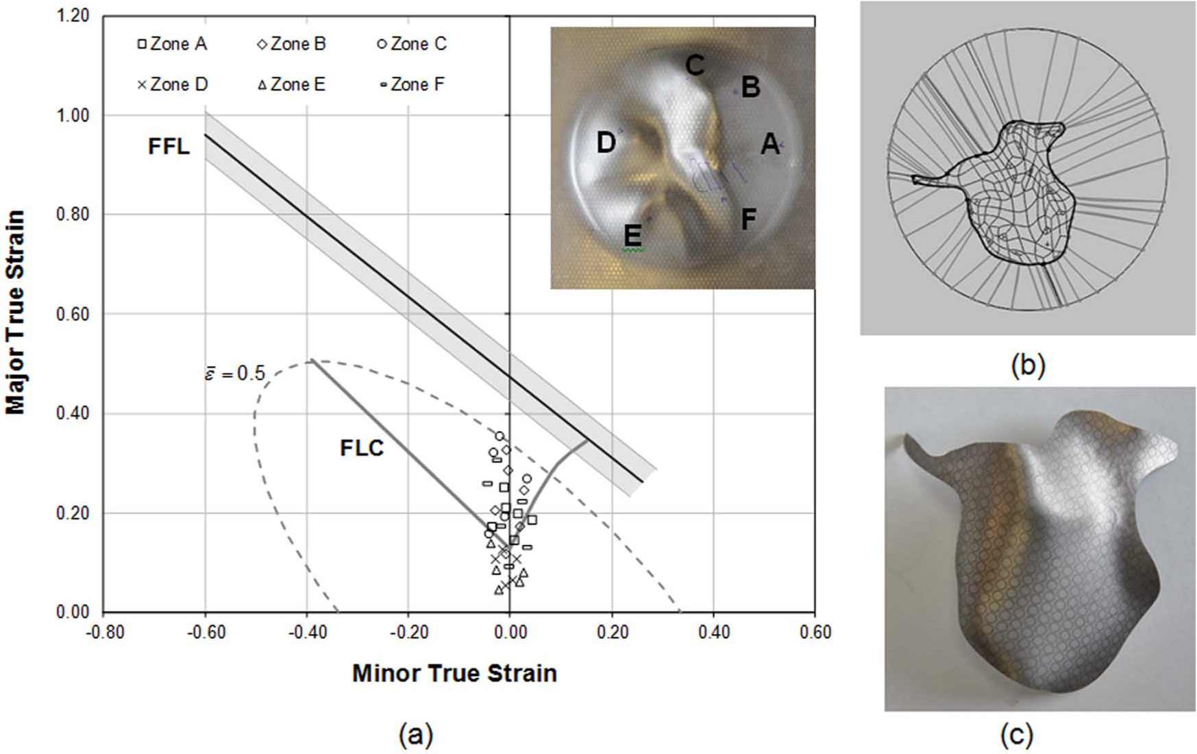
Simplified model of the facial implant successfully produced by SPIF: (a) forming limit diagram with identification of the zones A–F of the deformed blank, (b) schematic representation of the deformed blank with no indication of regions with drawing angles larger than the maximum admissible drawing angle ψmax and (c) photograph of the implant.
The above-mentioned procedure allowed the maximum strain values to decrease and to be moved back to the safe region of the fracture forming limit diagram (i.e. to the region below the FFL) in order to produce a sound facial implant by SPIF. Conversely, the maximum effective strain was found to be located in region C with a value
The overall investigation allow authors to conclude that facial implants with extreme angles made from titanium grade 2 raise challenges to be produced by SPIF due to the relatively small value of the maximum admissible drawing angle ψmax. Resorting to multistage tool path strategies will need to be put forward in order to fabricate critical geometries such as the orbital cavity of the actual facial implant.
Conclusion
The article addressed fundamental topics in design and manufacturing of medical implants by SPIF that will need to be considered by production engineers and surgeons in order to fabricate low-cost, patient-specific implants.
The presentation was based on a simplified model of a facial implant made from titanium grade 2 and special emphasis was given to the interaction between circle grid analysis and formability tests in order to explain failure by cracking at critical geometric features of the facial implants. Characterization of the failure limit by cracking in the principal strain space by means of a straight line falling from left to right with a slope approximately equal to −0.8 combined with the identification of the maximum admissible drawing angle
Footnotes
Declaration of conflicting interests
The authors declare that there is no conflict of interest.
Funding
This research received no specific grant from any funding agency in the public, commercial, or not-for-profit sectors.