
Abstract
Background and aim:
The objective of this study was to demonstrate how a load cell and force–moment curves can be used outside of a gait lab to directly measure and evaluate the transverse plane loading moment on transtibial residual limbs.
Technique:
A load cell was attached distally to the socket of three transtibial amputees who walked a straight path and a circle of 3.048-m diameter with the prosthetic foot both inside and outside the curved path.
Discussion:
Compared to straight path walking, transverse plane moment decreased when the foot was on the outside of the curved path. When the foot was on the inside, the moment did not exceed that for straight path walking for two participants; maximum transverse moment was approximately 0.15 N m/kg of body mass. Force–moment curves indicated that each participant’s gait was unique, but underlying similarities were observed with respect to each of the three conditions.
Clinical relevance
A load cell in conjunction with curved and straight path walking and force–moment curves can be used outside of a gait lab to measure and examine the transverse plane loading on the residual limb.
Background and aim
The purpose of this study was to examine the feasibility of developing data on the transverse plane moment loads that affect the residual limbs of persons with transtibial amputations without the need for a traditional gait lab. Instead, the study examined use of a load cell outside the lab to directly measure transverse plane moments, curved path walking, and force–moment curves–methods that could be replicated in many clinical settings. The occurrence of a transverse plane moment at the base of the socket during walking indicates that the residual limb is attempting to rotate relative to the socket but the rotation is being resisted by the pressure and shear force generated between the residual limb and the socket interface. It is influenced by resistance of the leg to rotation at the joints and at the ground where friction is generated between the sole of the shoe and the walking surface. A transverse plane moment experienced by the residual limb that creates discomfort, tissue breakdown, or gait problems may indicate the need for a device commonly referred to as a “torque absorber” or socket interface or foot designs that absorb and reduce the peak transverse plane moments. The literature reports several studies of transtibial transverse plane joint rotation that estimate transverse plane moments using standard gait lab methods,1–5 but none have measured moments directly and none have utilized force–moment curves, particularly for individuals with transtibial amputation fitted with a socket.
Real walking environments outside of the gait lab often involve turning movements and following curved pathways. Previous studies have shown that the peak transverse plane moments occurring during curved path walking are different from those experienced during straight path walking because of the necessary turning movements,2–5 which affect the orientation of the pelvis in the transverse plane and the number of degrees of relative motion between the pelvis and the femur.6,7 A related question is whether the magnitudes of the peak transverse plane moments are affected by the location of the prosthetic foot on the inside or outside of a curve. Peak transverse plane moments are of interest because they occur when the greatest resistance is developed as the residual limb attempts to rotate and are an indicator of the load to which the transtibial residual limb is subjected.
It is very challenging to study curved path walking in the standard gait lab, which typically is instrumented to examine only straight path walking. Although the location of force plates for straight path walking can be adjusted along the path of walking, it can be very difficult or impossible to make force plate adjustments for curved path walking; reorientation of the force plates may be needed. Sources of potential error include small motion capture volumes, the need for a participant to target force plates while tracking a curved path, and the challenges of achieving consistent and error-free marker placement. Forces and moments at the base of the socket can only be estimated by use of inverse dynamics methods, which require assumptions about ankle joint center locations that may not apply to prosthetic feet.8–12 Traditional gait lab studies use global reference frames fixed to the force plate and require extensive use of assumptions and extrapolation of force plate measurements to estimate transverse plane loads on the moving prosthesis. Requirements exist that may be impractical to implement in a clinical setting. But with a load cell attached rigidly between the distal end of a prosthesis socket and the pylon, transverse plane moments can be measured directly in any walking environment, including both straight and curved paths.13,14 The load cell provides data in the moving reference frame of the prosthesis instead of a reference frame fixed to the ground, which can be helpful for directly examining many aspects of prosthesis load-residual limb interaction and could lead to improved evidence for the design and fitting of sockets. Load cells have been used to study the loads on osseointegration implants15–23 and the relationship between alignment and the sagittal and frontal plane moments generated during prosthesis use.24–27 Clinical practice requires prosthetists to evaluate the needs of each individual patient and patient responses can vary. The goal of exploring methods that prosthetists in clinical settings could use provided the rationale followed in this study for undertaking within-subject comparisons of conditions using student t-tests and the comparison of results using force–moment curves.
As measured by the load cell in this preliminary investigation, a transverse plane moment is the moment about the pylon created by force in a plane perpendicular to the pylon. The signs of the forces and moments presented in this study are expressed with respect to their impact on the residual limb as the reference object. The signs of the moments represent loads on a left residual limb based on the right hand rule. A negative moment during propulsion was a clockwise moment on the residual limb viewed downward toward the foot.
Since moment is equal to the cross product of the perpendicular distance between the line of action of a resultant force, r, and the magnitude of the resultant force, FR, differences in the magnitudes of transverse plane moments could be due to kinetic differences in the magnitude of the resultant force, geometric differences in the length of the moment arm, or both. A novel aspect of this study is the use of force–moment curves to simultaneously display relationships between transverse plane forces and the moments produced by them that otherwise would be difficult to detect when forces and moments are examined in isolation. Force–moment curves allow the relationships between forces, moments, and moment arms for an individual to be displayed in one graph and visually compared across conditions.13,27
Technique
Three unilateral transtibial amputees (2 males, 1 female), recruited through local clinics and professional contacts, provided preliminary data (Table 1). Inclusion criteria included the ability to undertake walking without loss of balance or an unsteady gait. Exclusion criteria included open sores and infection in the residual limb, sockets that fit poorly, amputations less than 1 year previously, and use of preparatory prostheses. All participants were examined by a certified prosthetist and, in keeping with the Declaration of Helsinki, all read and signed a Letter of Informed Consent that had been approved by the Institutional Review Boards (IRBs) of the University of Nevada, Las Vegas and the US Army Medical Research and Materiel Command. The participants, instrumentation, protocol, and details of data processing are described in detail in an earlier article; 13 the previous study examined only straight path walking whereas this preliminary study extends analysis to curved path walking.
Subject characteristics.
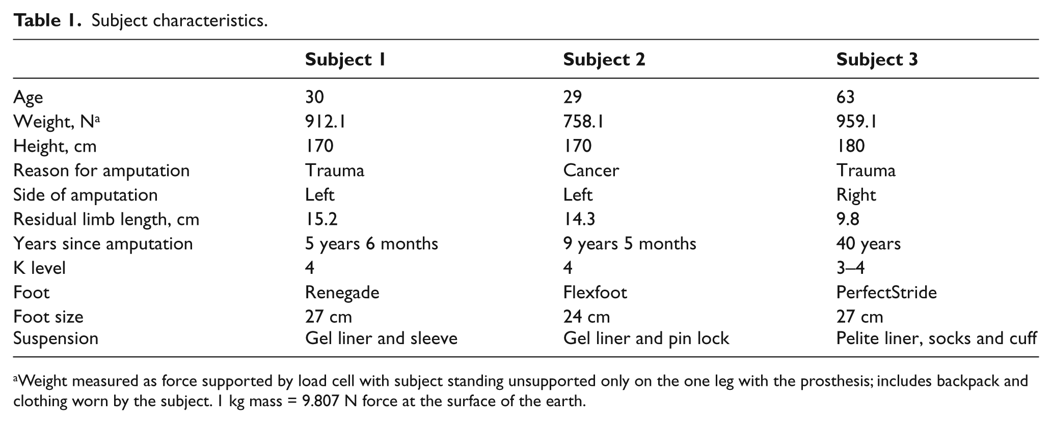
Weight measured as force supported by load cell with subject standing unsupported only on the one leg with the prosthesis; includes backpack and clothing worn by the subject. 1 kg mass = 9.807 N force at the surface of the earth.
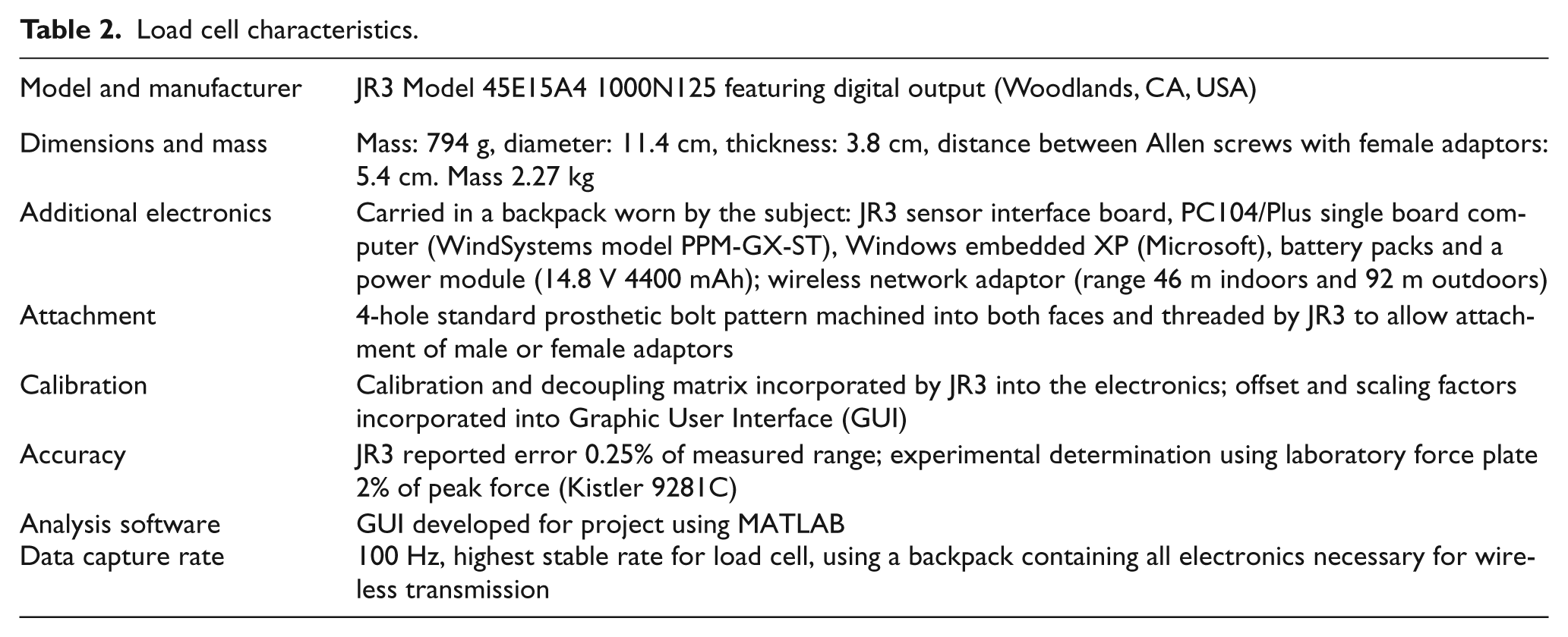
A JR3 Model 45E15A4 1000N125 load cell featuring digital output (Table 2) was secured between the pylon and socket, and a certified prosthetist achieved an alignment judged acceptable by the participant that attempted to recreate the original alignment the participants were using. All participants used their everyday or spare prostheses and indicated that they had adapted to their feet (Renegade, Flexfoot, PerfectStride) through prior use. None utilized torque-absorbing mechanisms mounted on the pylon.
Load cell characteristics.
Data collection involved straight path self-selected comfortable speed (SSCS) walking and subsequently, without changing feet or alignment, circular path walking during which participants followed a circle with a 3.048-m (10-foot) diameter at SSCS with the prosthetic foot on the inside of the circle and on the outside. Walking on the circular path ensured that 10 consecutive steps taken under identical experimental conditions could be obtained for examination of mean values. The 3.048-m diameter was chosen for convenience; given the paucity of data on curved path walking at the time of study design, there was no evidence to recommend selection of a larger or smaller diameter. Based on the author’s clinical experience, a circle of 10-ft diameter was estimated to be sufficient to reveal differences in transverse plane moments for the three conditions.
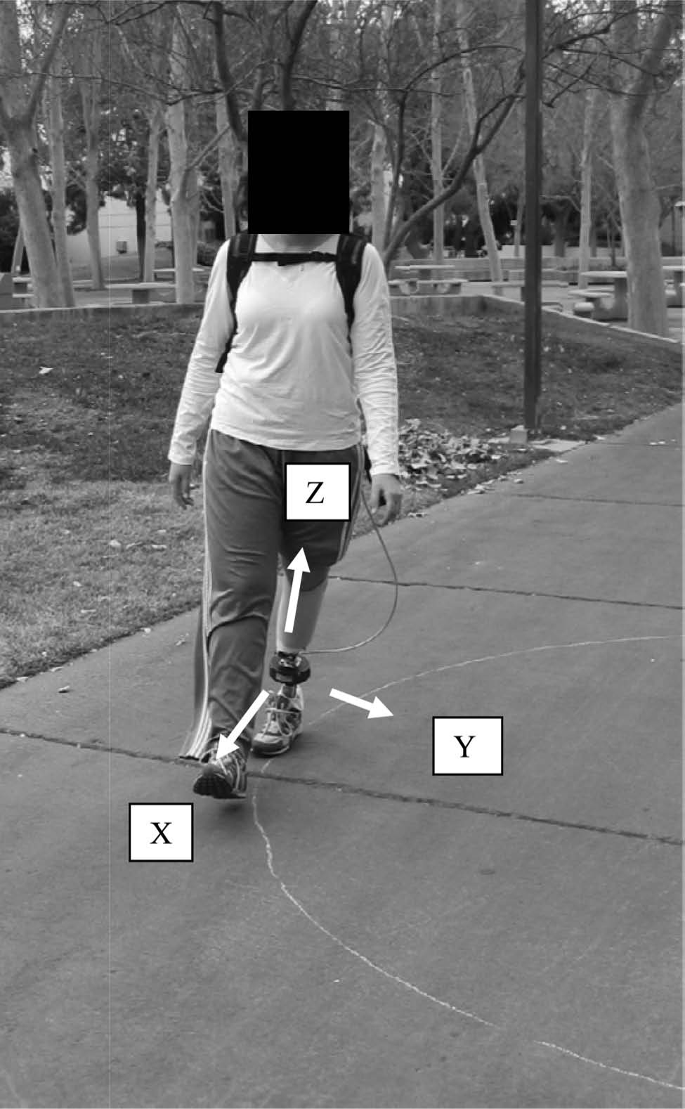
To facilitate comparisons, all load cell data were normalized—forces were divided by the standing weight of each participant as measured by the load cell (N/N) and moments were divided by the mass of each participant (N m/kg). Transverse plane moments were measured as moments about the Z-axis (long axis) of the load cell parallel to the pylon (Figure 1) and are presented in Figure 2 and Table 3. Resultant force in the transverse plane was computed as FRT = (FX2 + FY2)1/2 and is shown in Figure 3 and Table 3. The length of the moment arm in the transverse plane, also shown in Table 3, was computed as rT = MZ/FRT.
Curved path walking.
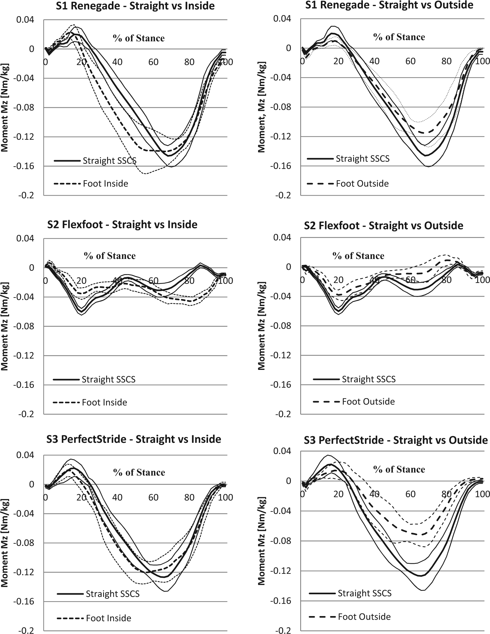
Comparison of transverse plane moments, MZ.
Peak normalized transverse plane moment and associated resultant force, moment arm, and gait parameters.
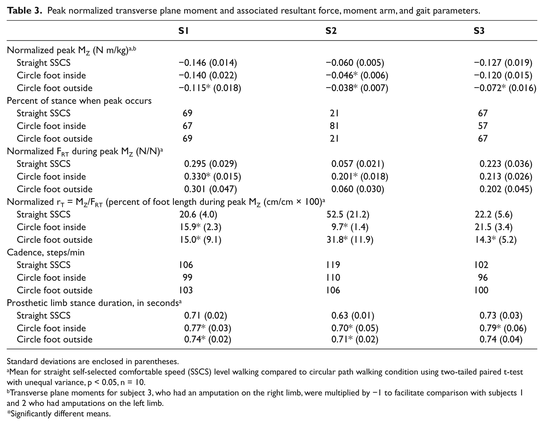
Standard deviations are enclosed in parentheses.
Mean for straight self-selected comfortable speed (SSCS) level walking compared to circular path walking condition using two-tailed paired t-test with unequal variance, p < 0.05, n = 10.
Transverse plane moments for subject 3, who had an amputation on the right limb, were multiplied by −1 to facilitate comparison with subjects 1 and 2 who had amputations on the left limb.
Significantly different means.

Comparison of transverse plane resultant forces, FRT.
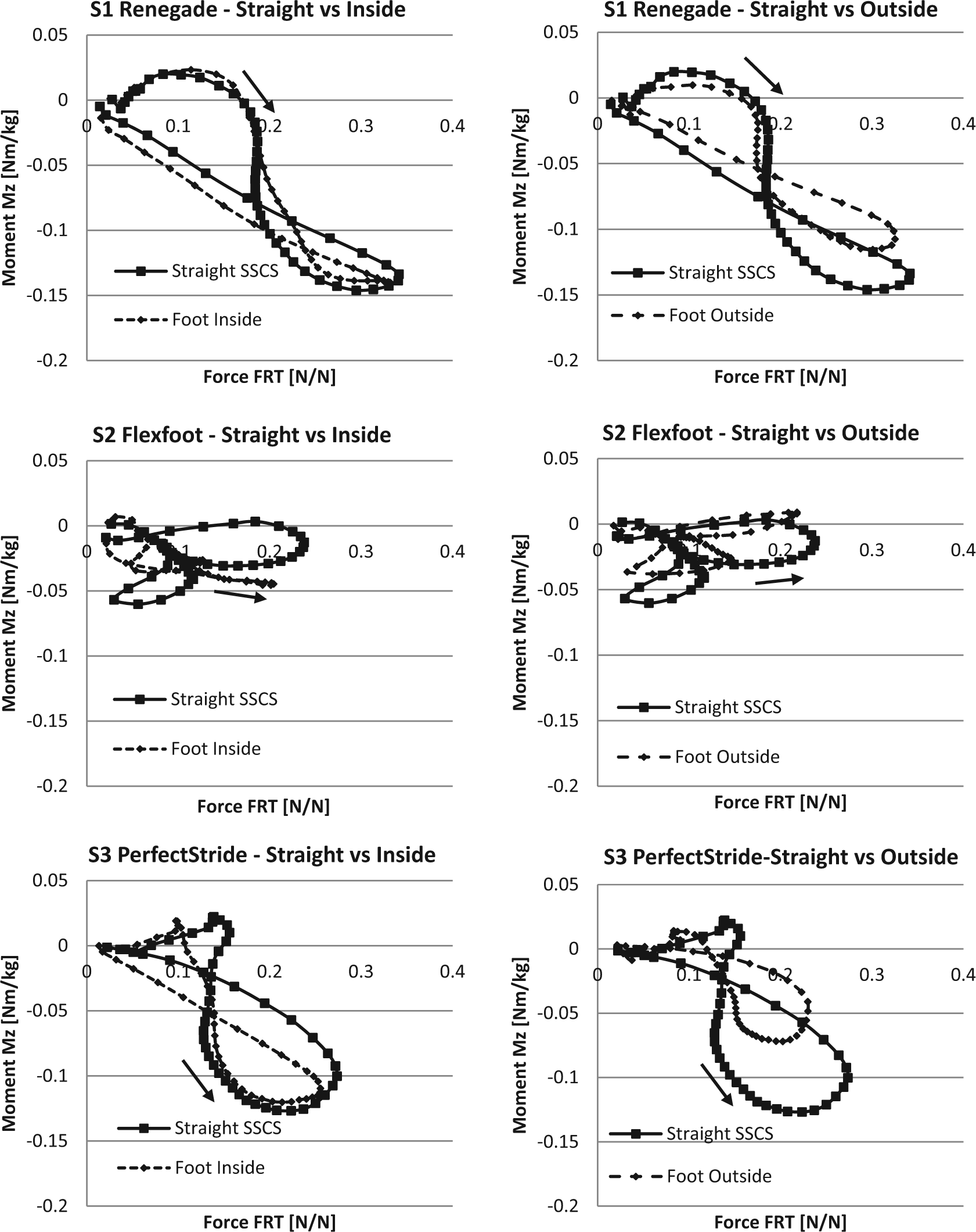
Force–moment curves are shown in Figure 4, which graphs the simultaneous values of both the normalized transverse plane moment and the normalized resultant transverse plane force that produced it for all data points during stance. The curves show how resultant force and the corresponding moment change together as stance progresses. The relative lengths of the moment arms for any two points on a single curve or different curves for the same participant can be estimated by comparing visually the slopes of the lines connecting the origin of the graph with the points since the slopes of the lines, normalized MZ/FRT, are in constant proportion to rT.
Comparison of transverse plane force–moment relationships.
Two-tailed paired t-tests with unequal variances, p < 0.05, and n = 10 consecutive steps were used to compare the mean peak moments and the associated resultant forces and moment arm lengths for the straight path walking condition to each of the two circular path conditions for each participant. Cadence and prosthetic limb stance duration were determined based on the rate of data capture of the load cell (100 Hz) and the times when heel contact began and toe-off ended in the data stream.
Discussion
Biomechanics
The downward action force generated by the body during gait is transmitted through the leg and shoe to the ground, where it produces an upward ground reaction force that is opposite and equal in magnitude, provided there is no slipping of the shoe on the ground. The transverse plane component of this downward action force is resisted by an equal but opposite friction force generated between the sole of the shoe and ground. The friction force allows a transverse plane moment to be generated about the pylon, which can be measured by a load cell attached to the pylon at the distal end of the socket. At equilibrium, the moment in the pylon is equal in magnitude to the resisting moment created by the residual limb where it contacts the socket interface. The occurrence of a resisting moment indicates that the residual limb and socket are attempting to rotate relative to each other, with the resistance to rotation being generated by intra-socket pressures and shear forces over regions where the residual limb contacts the walls of the socket interface, up to the limit allowed by friction between the shoe and ground or patient discomfort. A transverse moment in the pylon during stance indicates that torsional stress is occurring at the anatomic knee joint when the leg is extended, because rotation at the tibiofemoral joint usually is negligible due to the anatomy of the knee. 28 Torsional stress is also transmitted to the hip, but the hip is designed to rotate; the rotation is controlled by the action of the hip rotator muscles.
Geometric considerations indicate that when individuals walk on a curved path, their bodies must rotate toward the center of curvature during stance. It follows that in order for body rotation to occur, when the foot is on the outside of the curve, less rotation of the pelvis should occur relative to the foot and/or when the foot is on the inside of the curve, more rotation of the pelvis should occur relative to the foot. With the foot inside the circular path, the rotation of the pelvis relative to the femur through a greater angle than that occurred with straight path walking was expected to be associated with a greater transverse plane (resisting) moment, and with the foot outside the circular path, the rotation of the pelvis relative to the femur through a smaller angle than that occurred with straight path walking was expected to be associated with a smaller transverse plane (resisting) moment.
Straight path SSCS walking
During straight path SSCS walking, S1 and S3 exhibited mean normalized transverse plane moments, normalized forces, and force–moment plots that were uniquely different, but there were similarities in overall appearance (Figures 2, 3 and 4). With both participants, the transverse plane components of the ground reaction force created smaller positive moments during heel loading and larger negative moments later in stance during propulsion, and the force–moment curves, which show the relationship between resultant force and moment, had the appearance of distorted and inclined figure eights. The maximum transverse plane moments were roughly 12%–19% of the maximum sagittal plane moments that occurred during propulsion. 27
Force–moment curves for S2 appeared very different from S1 and S3 for all conditions. S2’s maximum moment occurred early in stance and was followed by a trend of decreasing magnitude. The maximum negative value of the moment was only 41%–47% of the maximum for S1 and S3, which indicated a lower rotation moment on the socket.
Foot inside
With the foot on the inside of the circle, for S1 and S3, the maximum mean moments during propulsion were not significantly different in magnitude from those for straight path SSCS walking. Previous studies using a circle of 2-m diameter concluded that peak moments increased with the foot inside.2–5 The force–moment plots in Figure 4 indicate that the moments did increase for S1 and S3, but for intervals subsequent to the occurrence of the peak moment.
The maximum mean normalized transverse plane moment for both straight path SSCS walking and walking with the foot inside appeared to be approximately 0.15 Nm/kg. For S1, there was an associated significant increase in the resultant force that was compensated by a significant reduction in the length of the moment arm. There were no significant changes in either resultant force or moment arm for S3 during the peak moment for the foot inside condition, although following the peak moment, a smaller maximum resultant force and greater moments were observed.
For S2, when comparing the foot inside the straight path SSCS walking, there was a significant decrease in the magnitude of the peak moment—just the opposite of what would be expected based on previous studies2–5—and a significant increase in the resultant force along with a significant reduction in the length of the moment arm. But the force–moment curves of Figure 4 indicate that during late stance, the moment during propulsion did increase, in agreement with the previous studies.
Foot outside
As shown in Figure 4, with the foot on the outside of the curved path during stance, the mean moments and peak moment of MZ were lower in magnitude than for straight path SSCS walking for all three participants for given values of the resultant transverse force, FRT. This finding was in agreement with previous studies.2–5 The mean peak transverse plane moments on the residual limb during late stance were 21.2%–43.3%, significantly lower than for straight path walking (Figure 2 and Table 3) for all three participants. Figure 4 also indicates shorter moment arms during propulsion for a given level of force.
Interpretation
There were relatively consistent changes in the peak moment and length of the moment arm among the three participants with respect to walking with the prosthetic foot outside the circle even though each participant used a prosthetic foot of different design and each force–moment curve appeared unique. As shown in Figure 4, the peak moment during the propulsive phase was less when the foot was outside the curve than that occurred for straight path SSCS walking, but was not greater when the foot was inside the curve, although the shapes of the force–moment curves changed noticeably with location of the foot. With the previous studies,2–5 participants not only had to track a circle of very small diameter but also had to target force plates. In this study, which involved a circle of larger diameter and did not require participants to target force plates, cadence was found to be slower with curved path walking, and prosthetic limb stance duration increased significantly for both curved path conditions, with only one exception (Table 3), which suggests that the gait requirements all people face when tracking a small circular path may influence results.
It is conjectural, but intuition suggests that amputees may adopt gait strategies to minimize the relative rotation moment of the socket when the prosthetic foot is inside, provided they are not required to target force plates. Reducing the length of the moment arm or the magnitude of the resultant transverse plane force or allowing the foot to rotate could keep the moment below a maximum value. Figure 4 indicates that the resulting transverse plane biomechanical response of each participant was different when the foot was inside. In contrast, walking with an outside prosthetic foot appeared to reduce the transverse moment for all the participants and produced similar appearing curves.
There has been disagreement as to whether transtibial prostheses require some method of torque absorption. 1 The results of this preliminary study indicate that a load cell, in conjunction with force–moment analysis, makes possible the direct measurement and examination of transverse plane loads on the residual limbs of individual transtibial amputees in real-world walking environments. There may be a diameter between 2 m and 3.04 m at which residual limb peak transverse plane moments increase when the prosthetic foot is inside the curve.
Participant perceptions of discomfort or other gait-related problems and the occurrence of foot slippage could be included in future analyses. The magnitude of the transverse plane moment also could be affected by socket interface design. A clinical question of relevance remains unanswered: for what level of peak transverse plane moment encountered by transtibial amputees during their daily activities should a torque-absorption design be indicated?
Key points
A load cell allows the transverse plane moments that impact the residual limb to be measured outside the gait lab, and curved path walking can be used to examine the magnitude of the peak moments under different real-world walking conditions.
Force–moment analysis allows residual limb loading to be examined throughout stance and to discover relationships that are difficult to detect when forces and moments are examined in isolation
Compared to straight path walking, the transverse plane moments on the residual limb caused by walking on a curved path may be less when the prosthetic foot is on the outside of the curve and greater or equal to straight path walking when the foot is on the inside; preliminary results based on two participants suggest that the maximum value of the moment may be approximately 0.15 Nm/kg of body mass for a curved path of approximately 3-m diameter.
Footnotes
Acknowledgements
Appreciation is expressed to the Hanger Orthopedic Group, Inc. and BioQuest Prosthetics for help in recruiting research participants, Anup Miryala for assistance with GUI development and data collection, and to Jerry Fullerton, CPO (deceased) for initial contributions to the development of research objectives.
Conflict of interest
None of the authors have any financial or personal relationships with other people or organizations who could inappropriately influence their work.
Funding
The research was supported by the US Army Medical Research and Materiel Command [grant number W81XWH-07-2-0084].