
Abstract
The state of stress arising within an elastic wedge generated by an antiplane singularity present within it is studied. An analytical solution is derived with a unified generic approach. The singularity may represent either an anti-plane concentrated force or a screw dislocation. To validate the general solution, two degenerate cases are presented. Further, the image force present on the screw dislocation due to the wedge free boundary is obtained. It is found that when the screw dislocations are placed in the vicinity of the wedge surface, the image force will drive dislocations to the free boundary where they will be annihilated. This implies that a dislocation-free zone may exist along the free surface of the wedge. To demonstrate the application of the fundamental solutions, a formulation for a slip band under anti-plane loading with Green’s function method is provided. The solutions developed in this study may be used as building blocks to model the damage of material near a V-notch under versatile anti-plane load conditions or torsional loading.
Introduction
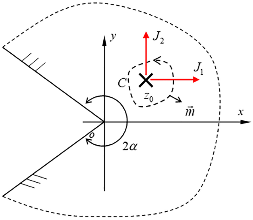
The solid shown in Figure 1 is generally called a “wedge” when its internal angle is
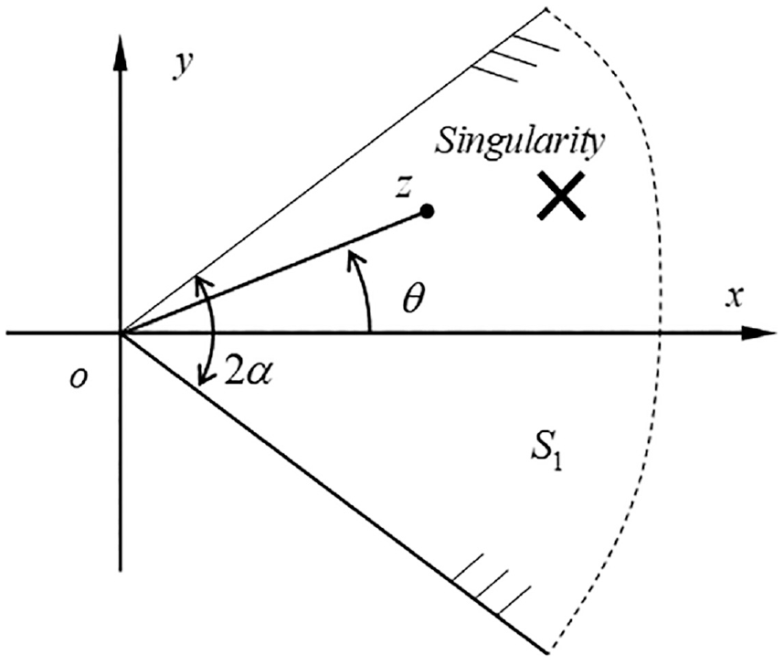
The configuration of a wedge interacting with an anti-plane singularity denoted by the cross sign. The singularity is arbitrarily located within the wedge, the x-axis is set along the bisector line of the wedge, and the wedge internal angle is within the range
The wedge is a common feature necessarily figuring in many mechanical components, including, for example, grooves for retention clips, or power transmission, as in the spline. Also, wedge-shaped crack problems are observed more often in practice, compared with parallel slits. A knowledge of the stress field within wedges is essential during design and fatigue assessment. The wedge problem is of special importance in elastic mechanics because of its fundamental significance, its widespread application, and its theoretical challenge. To determine the stress distribution within a wedge for various kinds of load condition, great efforts have been put into studying this topic so that wedge mechanics turns to be one of the most classical problems in elasticity.1–4
In the literature, studies of the wedge under antiplane loading have been conducted for a long time.4–7 Three approaches have been employed to cater for various antiplane load conditions: (i) the first one is Williams expansion approach,8–11 which approximates the real stress function of the problem in a simple form to calculate the stress concentration factor at V-notch tips, (ii) the second is one which takes the complex stress function of the problem in finite representative terms,12–17 which has been used to approximate the stress distribution, and (iii) the third one is the Mellin transform technique,18–20 which may be used to examine crack problems within wedges. It should be pointed out that, in theory, the Mellin transform is a rigorous and feasible approach to find exact solutions; however, when applied in practice, analytical solutions can be derived only for several very simple problems, and generally, numerical methods have to be further employed for common problems.20,21 Here, we mainly present typical developments in cases subject to antiplane loading, and the detailed review on these approaches applied to the cases under “in-plane” loading has been separately given in a recent work. 22
The work described above represents progress in our understanding of the problems under antiplane loading, but some remaining challenges still exist. First, strictly speaking, the aforementioned analyses have been mostly conducted in an asymptotic or approximate sense. It is hard to treat various antiplane load conditions, including spatially varying far-field loads, and near-field loads such as body forces or imposed displacement loads in the neighborhood of notches. Secondly, micromechanics analysis in literature just focuses tightly on the dislocation-wedge interaction problems. These are very powerful in applications, but lack a generic approach to develop the solutions for the generalized singularity-wedge problem, such as when the singularity represents a antiplane force or a more complex strain nucleus such as point-wise defined residual strain. These challenges demand a rigorous and thorough analysis of the generalized singularity-wedge problem. In this paper the interaction of a wedge with a generalized antiplane singularity is studied, which complements the recent efforts in establishing the corresponding solution for in-plane loading. 22
The aim of this study is to propose a generic approach to treating wedge problems, and then specifically to develop a fundamental solution for a wedge interacting with a generalized anti-plane singularity. The singularity may be either an out-of-plane concentrated force or a screw dislocation, or various combinations of them, which may lead to a moment load, a residual stress (or strain) state, and so on. 23
The basic geometry we will consider is shown in Figure 1, in which, the singularity is arbitrarily located within the infinite wedge solid. The analysis procedure is outlined as follows: first, the complex formulation for anti-plane deformation and the generalized anti-plane singularity is presented, and the specific model is provided. Afterward, the solution for the interaction between the wedge and the singularity is derived. Subsequently, two degenerate cases are presented: first a half-plane solid containing a concentrated body force, and secondly a semi-infinite crack interacting with a singularity. Later on, the image force present on the screw dislocation is derived, and the application of the fundamental solutions with Green’s function method is demonstrated through a slip band formulation. Finally conclusions are drawn.
The complex framework and its formfor a generalized anti-plane singularity
In this section, complex variable formulas for antiplane problems and boundary conditions are introduced. The generalized singularity model is introduced which provides a basic concept for subsequent analysis.
The complex potential formulas
In the anti-plane shear deformation of an isotropic elastic material, the in-plane displacements vanish, that is
where

where the comma followed by a subscript 1 (or 2) indicates differentiation with respect to
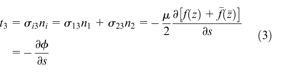
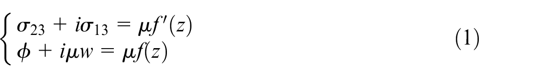
where
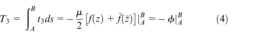
Equations (1) and (4) will be frequently used in the following manipulation.

Framework for anti-plane deformation of a gene-ralized singularity (shown here by a cross sign) embedded within a plane solid whose boundary is L.
The complex potential for singularities
A generalized anti-plane singularity, located at
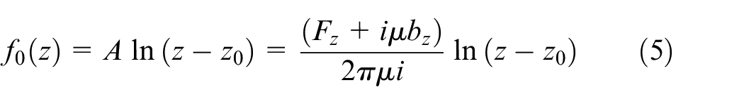
where
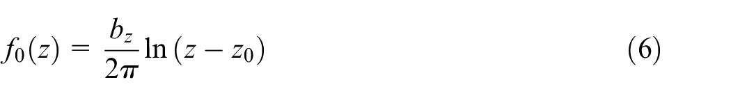
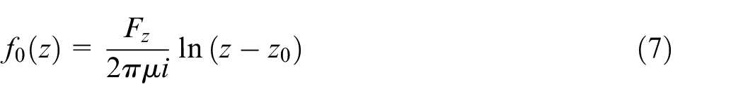
while if
With equation (5) established, the complex potential for an anti-plane concentrated moment or an anti-plane eigenstrain nucleus may also be derived.25,26 For example, the complex potential for a point-wise anti-plane eigenstrain located at the point
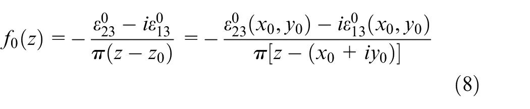
where
In the following manipulation, we will take the generalized singularity expressed in terms of equation (5). The results for other generalized singularities can be derived in the same way.
Formulation
Consider the wedge shown in Figure 1, where a generalized antiplane singularity is located in the material. For this geometry, the complex potentials within the elastic solid, identified as

where
We introduce a one-to-one conformal mapping function for everywhere, except the point
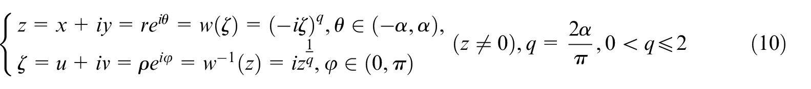
This maps the configuration in Figure 1 (or Figure 3(a)) into the one shown in Figure 3(b).
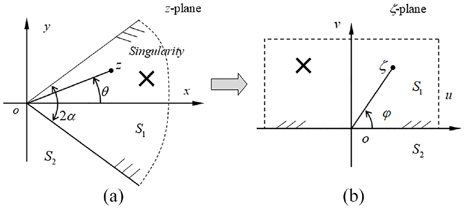
(a) Physical model, where the singularity located within the wedge, x axis is set along the bisector line of the wedge and (b) auxiliary plane.
It may be observed from Figure 3 that the material
In terms of the mapping, equation (4) can be rewritten as
and equation (9) will be transformed to

in which, accordingly,

Because equation (10) is a one-to-one conformal mapping (except the point
where
in which
The following operation is conducted within the
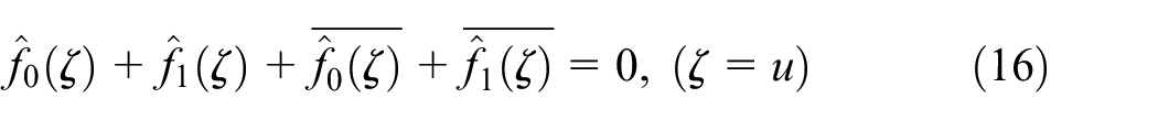
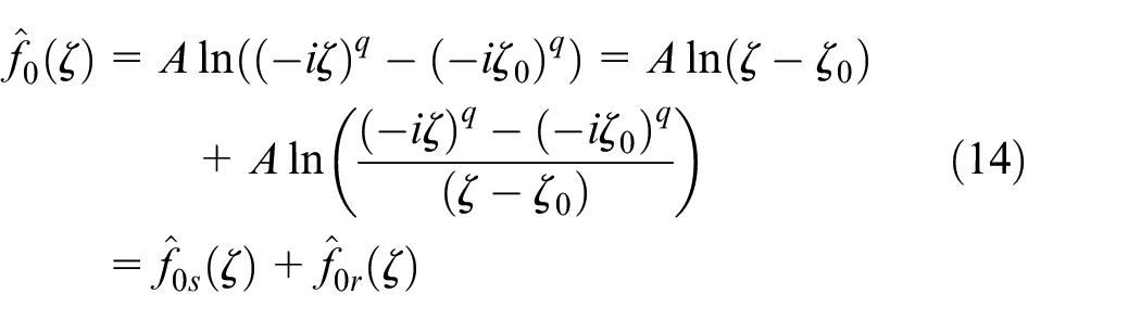
Further, by substituting equation (14) into (16), it follows that
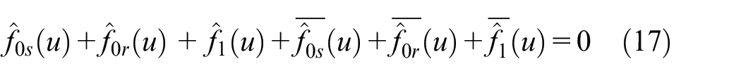
This result may be rearranged to give
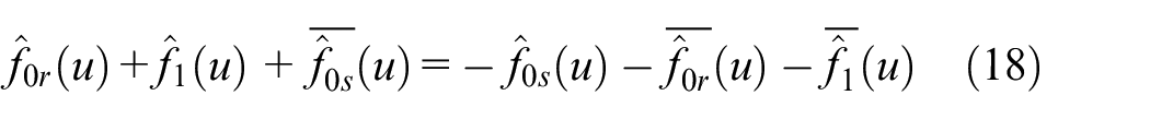
Equation (18) is a typical boundary value problem in terms of complex variables with a specific mapping, from which
Solution
By applying the standard analytic continuation argument to equation (18) and according to Liouville’s theorem, 27 we may obtain
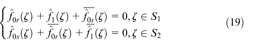
Thus,
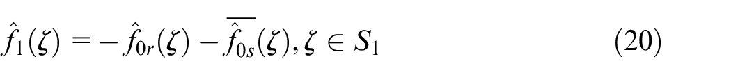
In terms of equation (15), equation (20) may be rewritten as
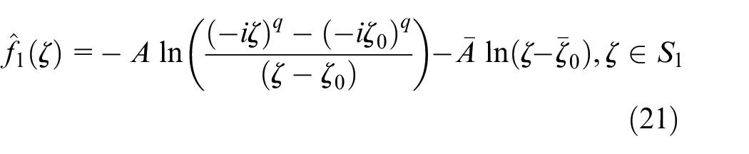
It can be verified that the solution (21) is regular for
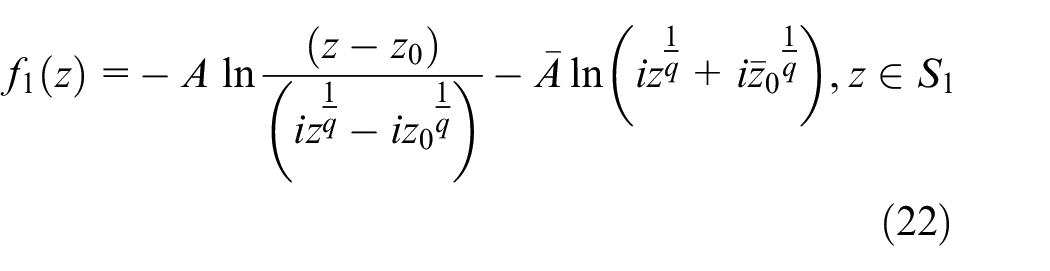
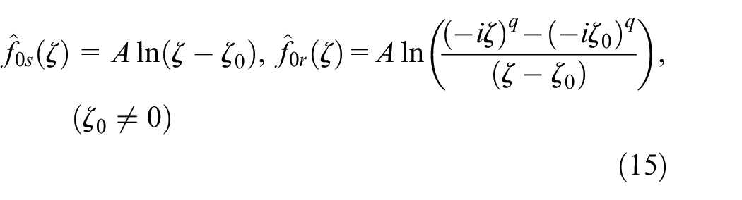
Solution (22) is regular in the wedge area in Figure 3(a), and by substituting it into equation (9), the solution for the wedge interacting with a generalized singularity is revealed, viz.
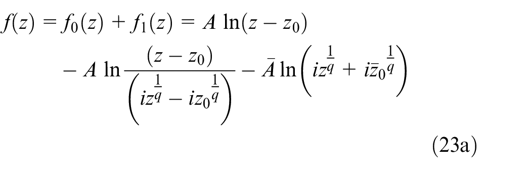
or
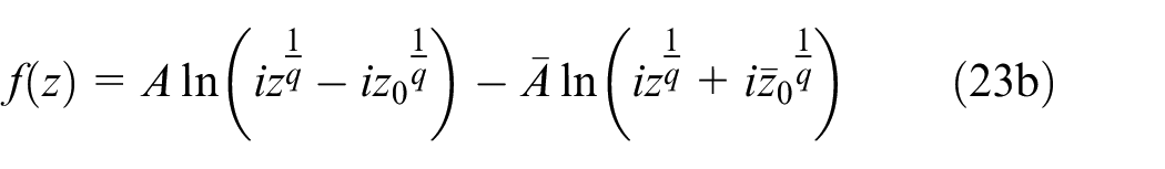
where
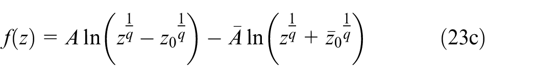
in which, the constant involved is ignored as it does not influence the stress field. If the singularity represents a screw dislocation, the stress due to it becomes
where
Solution (23) is the key result of this study. It should be restated that: (i) the angle of the wedge can be any value
Additionally, it should be explained that the procedure described in previous sections may be treated as a generic approach for developing other fundamental solutions. For example, the singularity may be thought of as representing a point-wise residual strain.
Solutions for typical cases
We obtained the general solution (23). In this section, as shown in Figure 4, two degenerate cases are presented to demonstrate its generality, and, to provide confidence in its reliability. The concentrated force acting at the vertex of wedge will also be also developed.
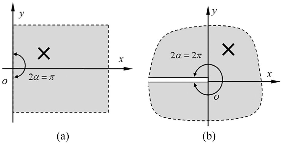
Typical cases: (a) a half plane solid and (b) a semi-infinite crack, respectively, interacting with a singularity.
A half plane solid interacting with a singularity
By setting
and then equation (23) becomes

where
For this case, we may take the limit
So that equation (26) becomes
Inserting equation (28) into equation (1), we get the fundamental solution for the antiplane case, complementing the well-known Flamant solution for the in-plane case.
A semi-infinite crack interacting with a singularity
By setting
and equation (23) becomes
where
The conventional stress intensity factor induced by the singularity may be defined as
Substituting equation (30) into the second equation of equation (1), and then supplying the stress expression to equation (31), after a straightforward manipulation, we find
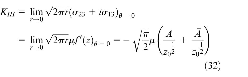
Whether the singularity is a screw dislocation or a concentrated anti-plane force, its stress intensity factor can be immediately found. For example, when it represents a screw dislocation,
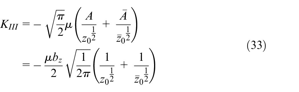
This result is completely consistent with the one by Thomson and Sinclair. 28 If the screw dislocation is located at x-axis, equation (33) turns to
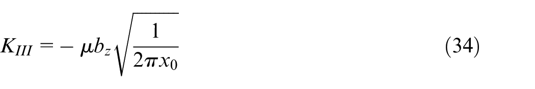
Equation (33) can be treated as the Green’s function to evaluate the crack tip stress intensity factor due to the presence of a cloud of screw dislocations in the vicinity of crack tip.
A concentrated force acting at the tip of a wedge
Because the mapping function introduced in this study is not conformal at the point
From consideration of equation (23c), we can see that the complex function for this case is
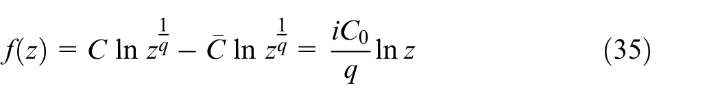
in which
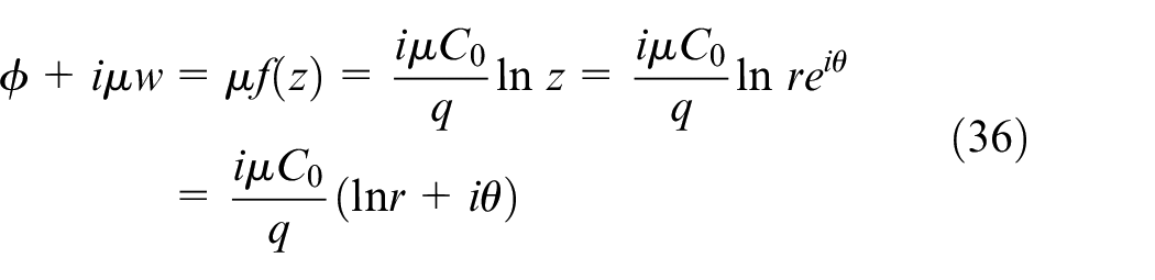
and by using equation (4),
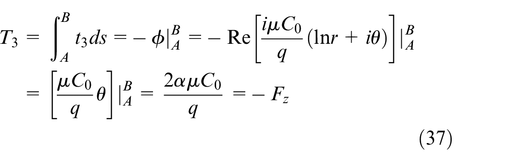
We have now fixed
Therefore, equation (35) becomes
It may be verified that equation (39) automatically satisfies the free-traction boundary condition. This is the complementary solution to the one developed in previous sections.
The image force on a screw dislocation due to the configuration of the wedge
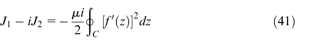
In this section, we will analyze the image force on a screw dislocation due to the configuration of the wedge, which may be evaluated through the vector path-independent integral
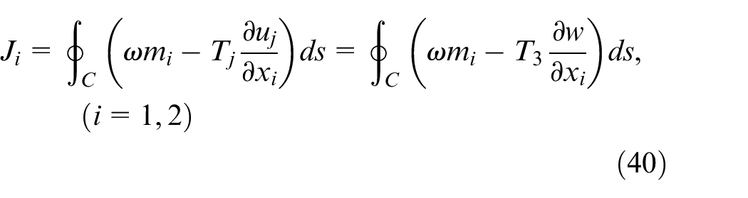
where
The image force on a screw dislocation due to the configuration of the wedge.
Alternatively, the combination of the two integrals can be expressed in terms of the complex potential as 30
From equation (23c), we know that
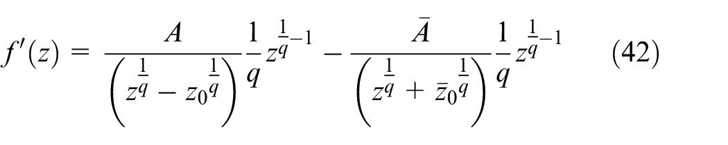
where
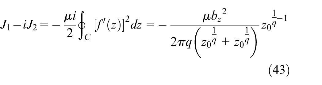
In consideration of
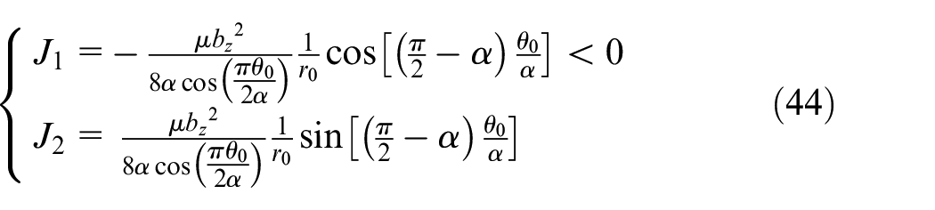
It is found from equation (44) that
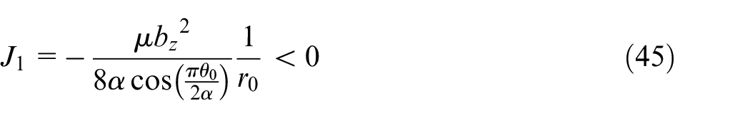
The image force on the screw dislocation results from the presence of the free boundary. It is a persistent force that tends to drive the dislocation out of the substrate toward the free surface. When the dislocation is located near the surface, the image force will be large enough to overcome the material internal resistance (the Peierls force) to impel it out of the substrate, which will result a dislocation-free layer. However, when the dislocation is located deeply inside of the substrate, the image force on the dislocation rapidly decreases, and it may be verified that when
This may shed some light on the mechanism of wedge-singularity interaction and at the same time, it may be regarded as a test to verify the derivation of the general solution.
Application: Formulation for a slip band under anti-plane external loading
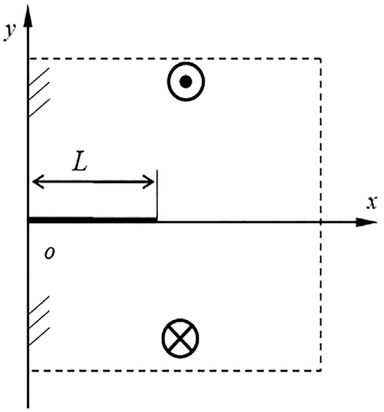
In this section, to demonstrate the application of fundamental solutions, a slip band (crack) subjected to some anti-plane loading shown in Figure 6 will be formulated with Green’s function method.
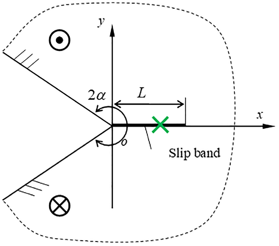
A slip band at the root of a V-notch under anti-symmetric loading.
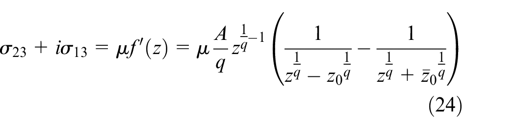
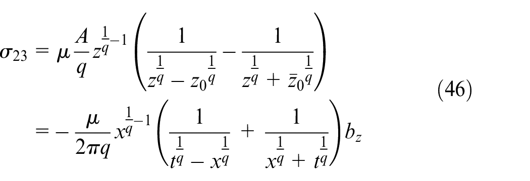
From equation (24), a screw dislocation is located at point t on x-axis, and the stress along the x-axis excited by the dislocation is
Then the traction along x-axis excited by a slip band shown in Figure 6 can be formulated through a continuous dislocation distribution technique as 31
where dislocation density function
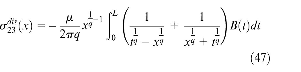
Substituting equations (47) into (48) leads to
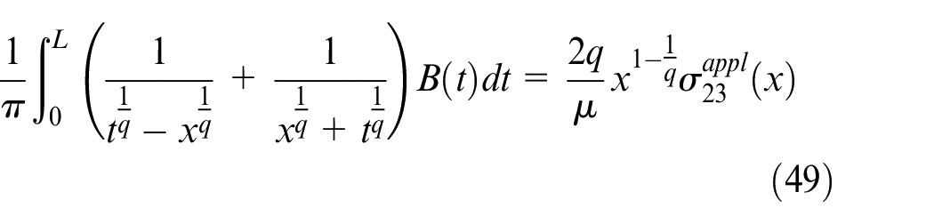
It can be seen from equation (49) that the singular integral equation looks a bit complex because of its singularity form, but at any rate the equation can be transformed into a singular integral equation of the first kind through the method of variable transformation. In a same way, the more complex slip band cases can be formulated, and the traction on the slip band due to external loads can be also evaluated through the Green’s function method. More detailed discussion will not be presented here. In the following, to show how to solve equation (49) and calculate the stress intensity factor at the slip band tip, without loss of generality, we present a simple case as shown in Figure 7.
A slip band developed from a half-plane edge under an anti-symmetric tearing load.
For this case,
This is a case where a surface crack is subjected to anti-plane loading.
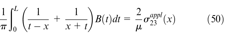
Equation (50) can be written into a standard form as
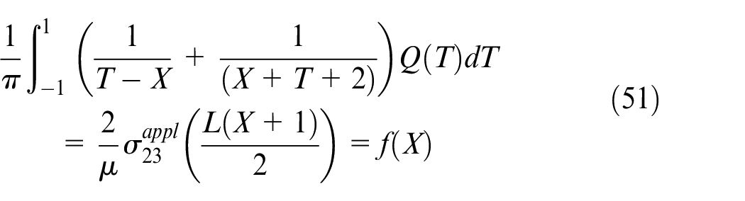
where
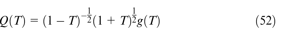
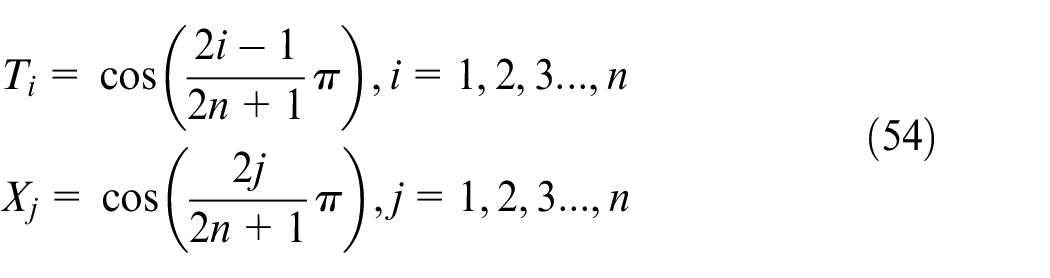
The numerical algorithm to equation (51) has been well studied,32,33 which is
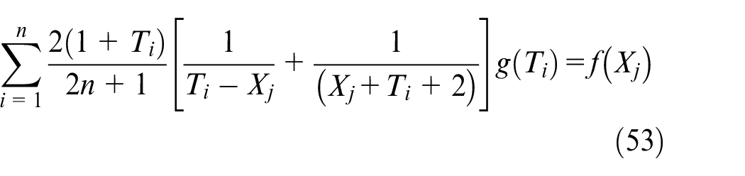
where
The regular function
According to the conventional definition, the stress intensity factor at the slip band tip can be defined as
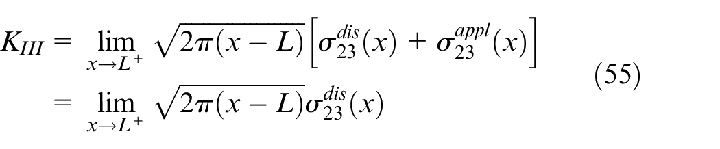
Inserting equations (47) into (55) leads
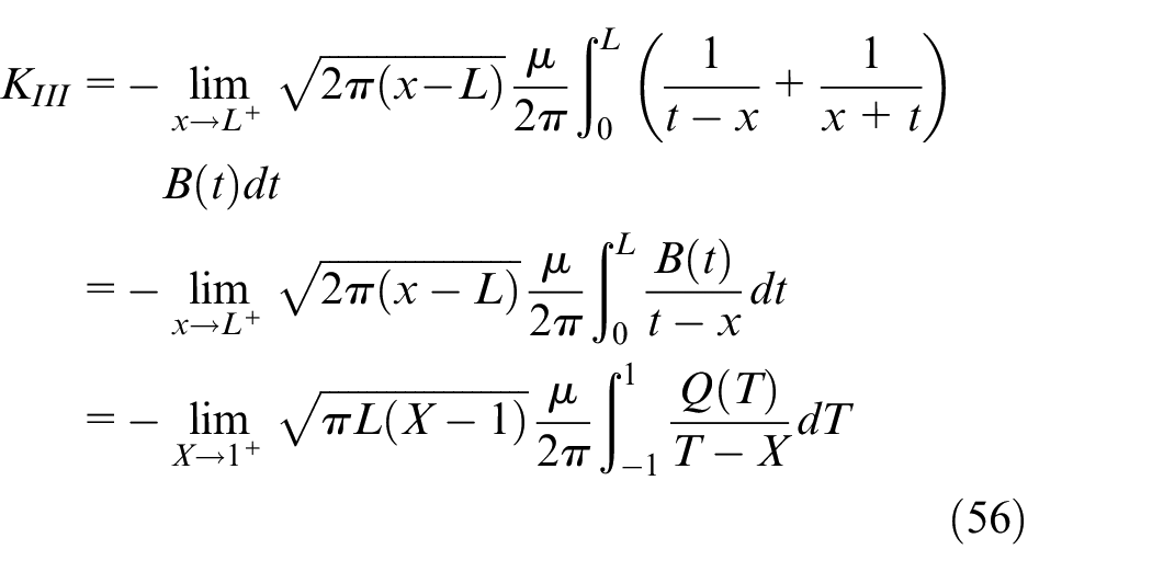
Further, replacing
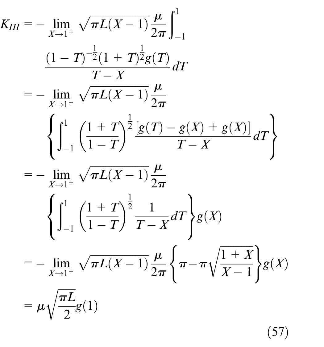
The general case shown in equation (49), where the notch opening angle is arbitrary, can be treated as this procedure, after it is transformed into a standard singular integral equation of the first kind.
Concluding remarks
In this study, using the complex conformal mapping technique, the analytical solution for a semi-infinite wedge, interacting with a generalized anti-plane singularity, has been derived. The singularity may be thought of as representing either a screw dislocation or a concentrated anti-plane force. To verify its correctness, a half plane solid and an infinite crack, respectively, interacting with a singularity have been presented. The image force on the screw dislocation due to the wedge configuration has been obtained, from which the dislocation-free zone can be predicted.
To demonstrate the application of the fundamental solutions, a slip band at the root of a V-notch under antiplane loading has been formulated through Green function method. The solutions developed can be used as building blocks to model V-notch damage problems and the wedge under complex load conditions. Moreover, the generic approach developed in this study may be also used to solve other similar problems.
Footnotes
Correction (October 2024):
In this article, title has been changed from “A generalized antiplane singularity within a semi-infinite wedgeof arbitrary angle” to “A generalized antiplane singularity within a semi-infinite wedge of arbitrary angle”.
Declaration of conflicting interests
The author(s) declared no potential conflicts of interest with respect to the research, authorship, and/or publication of this article.
Funding
The author(s) disclosed receipt of the following financial support for the research, authorship, and/or publication of this article: The support of the Sir Joseph Pope Fellowship from Nottingham University is much appreciated. The authors thank Rolls-Royce plc and the EPSRC for the support under the Prosperity Partnership Grant/Cornerstone: Mechanical Engineering Science to Enable Aero Propulsion Futures, Grant Ref: EP/R004951/1. This work was also partially supported by National Natural Science Foundation of China (grant no. 12072254).