
Abstract
This paper aims to examine the thermomechanical response of sintered silver die attachments in power electronics using finite element analysis (FEA). In this work, several material parameters of the sintered silver bonds are investigated. Additionally, two common solder creep constitutive laws including Anand and Garofalo models are also studied. To ensure the fidelity of the simulation procedures, the finite element (FE) models are first correlated with digital image correlation data. Afterward, the FE models are utilized to examine the influence of the material and creep models on the die attach stresses, strains, and plastic works. The expected fatigue and lifetime predictions of the sintered silver layer are thoroughly discussed, accordingly. The results proved that the die attach layer mechanical response is highly driven by the material parameters and creep modeling procedures considered throughout the simulations. Thus, the resulting fatigue life is evaluated. Finally, a general modeling guideline for simulating thermomechanical response of sintered silver die attachments in power electronics are provided in great detail.
Keywords
Introduction
The reliability performance of power electronics has become an essential concern for industry over the past few decades due to the rapid development in various engineering applications. Silver (Ag) sintered is a commonly adopted die attach technology in power electronics because of the improved electrical and thermal conductivity properties as well as thermomechanical reliability performance.1,2 Additionally, the Ag sintering process required relatively low-temperature bonding properties. 3 The mechanical failures of the sintered Ag die attachments are primarily triggered by the coefficient of thermal expansion (CTE) mismatch at the interface between the Ag layer and the Silicon (Si) chip in the power electronic module which results in high stresses and strain localization at the bonding interface.4,5 For the characterization of the stress-strain relationships in power modules, the finite element method (FEM) has been proven as a very effective and efficient analysis technique.6,7 In fact, the FEM has been immensely utilized in the reliability and lifetime evaluation studies of sintered silver attachments and many other solder bonds in electronics industry.8–11
For accurate and robust finite element analysis (FEA) of the stress-strain relationships estimation, it is very important to plug in and use as accurate as possible mechanical properties and material constitutive models throughout the simulations. For the analysis of the sintered silver bonds and other types of interconnects, there are several constitutive models that are suitable for replicating the creep behavior of such bonds.12–14 In fact, the careful selection of the creep law highly affects the simulations of the stresses and strains of the die attachment layer in power electronics. 15
Among many others, Anand’s unified viscoplasticity model,16,17 commonly referred to as the Anand model, is perhaps the most regularly used creep constitutive model in simulating the thermomechanical response of solders as it is able to capture the sensitivity as well as the history of temperature, strain rate strain hardening effects and the dynamic recovery. In other words, the Anand model simulates the isotropic hardening and/or softening process, the primary creep and the secondary creep responses of the solder layer.
Another commonly accepted creep model for the simulation of creep behavior of solder bonds is the Garofalo’s hyperbolic sine model. 18 This creep law is frequently applied in the cases where the solder mechanical response is basically driven by the steady-state creep.19–24
For the use of Garofalo’s law or the Anand model in simulation of the creep behavior of sintered silver, many researchers have chosen the Anand model and many other used the hyperbolic sine model of Garofalo.25–27 Yu et al., 28 preferred the use of Anand’s law because it considers the effect of strain rate and temperature dependency. Chen et al., 29 also used Anand’s model in their FEA studies of the thermomechanical performance of sintered Ag bonds along with the correlations with actual experiments. The results showed very well agreement between FEA and experimental observations. On the other hand, Liu et al. 30 selected Garofalo’s creep law to study the sintered Ag response in a thermally loaded double-sided power modules. The FEA numerical results were in great match with experiments in crack initiation locations and crack propagation routes. Weber et al. 31 were in favor of the use of Garofalo’s hyperbolic sine model in their simulations as the study was focused on the response of sintered silver die attaches in high-temperature experiments in which the steady-state creep (secondary creep) is predominant.
Apparently, it is shown that various creep constitutive models are available for simulating the mechanical response of the sintered silver die attachments in power electronics. Additionally, there are plenty of Anand model-based parameters of sintered Ag as well as other solder alloys that are reported in literature. However, there is a lack of information on the effect of the discrepancies between various creep models as well as material parameters on the mechanical reaction hence on the reliability performance of sintered silver bonding layers. Therefore, the present paper aims to examine the effect of the use of the Anand model and Garofalo’s hyperbolic sine law on the response of sintered silver solders. Additionally, this paper discusses the discrepancies between various literature-reported sintered silver material models on the stress-strain relationships and correlate that to the lifetime evaluations and predictions of the silver-based die attachments in power electronics using detailed finite element simulations.
The organization of this paper begins with a complete description of the creep constitutive models used in the study as well as the considered material parameters. The details of the test samples, and digital image correlation experiments are presented subsequently. Followed by the development and the validation process of the finite element models. Accordingly, the simulation results of each material and creep model including the sintered silver attachment displacements, stresses and strains, and the inelastic strain energy densities are thoroughly presented and discussed. Finally, the influence of every creep and material parameters on the sintered silver bonds lifetime evaluations and predictions are discussed in great detail.
Sintered silver creep constitutive models
Creep is often defined as the mechanical phenomenon that is driven by stress, strain rate and temperature. Creep is mainly associated with the melting point of the metal and to the loading temperature. In electronics, there are several creep constitutive models that are commonly considered for simulating the response of the die attachment like the Anand model and Garofalo’s hyperbolic sine law.
Garofalo’s hyperbolic sine law
Garofalo’s law 18 is usually implemented by Garofalo-Arrhenius equation to express the temperature-depended secondary, that is, steady-state, creep response of the sintered Ag die attaches, as:
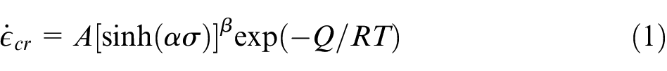
where
The Anand Model
Anand unified viscoplasticity creep constitutive model is often employed to capture the isotropic and as well as the viscoplastic behavior of metallic components as defined by a set of constitutive formulas: the evolutionary and the flow equations.16,17 There are two general important aspects of this model. First, Anand model needs no clear explicit yielding criterion and no loading/unloading standard. Consequently, the inelastic strain is supposed to initiate at all nonzero stress stages. Second, this model involves an internal scalar variable, often denoted by “s,” to interpret the isotropic resistance to plastic flow happened because of the initial state of the metallic material. This variable is commonly referred as the deformation resistance factor, which has the units of stress and it describes the overall isotropic resistance to the plastic flow arising from the primary isotropic strengthening mechanisms such as solid-solution strengthening, dislocation density and grain size effects. Consequently, the deformation resistance variable(s) is directly proportional to the value of the equivalent stress.
Mathematically, the Anand model is often written as:
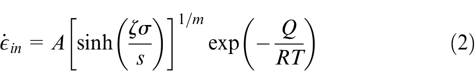
where
The internal variable
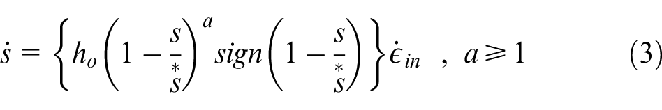
where
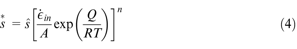
where
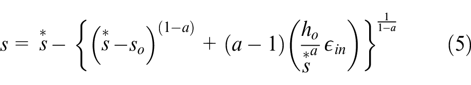
where
Hence, nine parameters (
By looking closely to the flow equation of Anand model equation (2) and in comparison, to Garofalo-Arrhenius equation (1) it can be seen that both equations follow the same mathematical form in which the pre-exponential factor and the activation energy terms are equal. Additionally, the strain rate sensitivity of stress (
Sintered silver material parameters
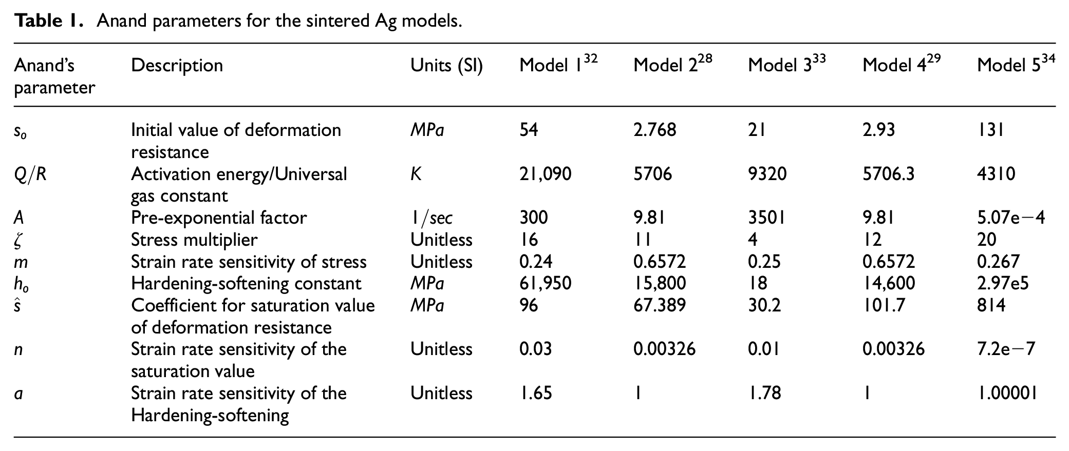
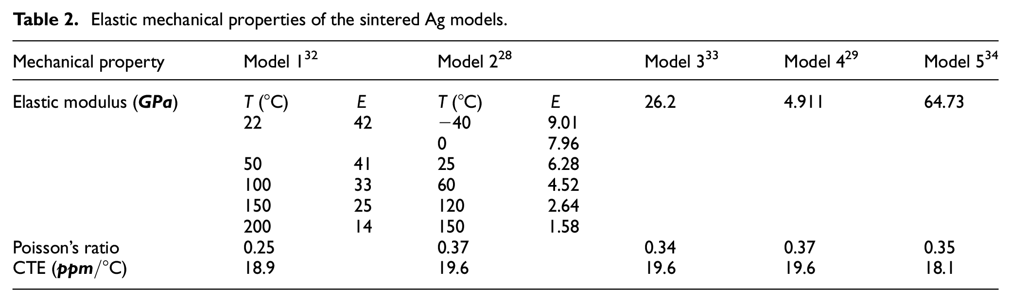
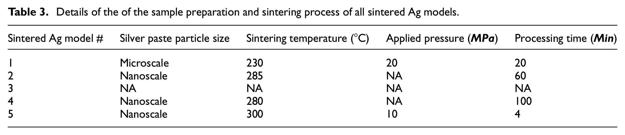
As stated earlier, the main goal of this work is to assess the differences between several Ag-based die attach material parameters using literature reported data and using different creep constitutive laws. Table 1 lists the Anand parameters of five Sintered Ag models from different literature sources and Table 2 reports the elastic properties of these models. The details of the of the sample preparation and sintering process including the silver paste particle size, sintering temperature, applied pressure and processing time are listed in Table 3. The status of NA (not available) appears in this table to state that there was not enough information in the literature source regarding that specific detail. It is important to mention that there was no data on the sintered silver details of Ag Model 3.
Anand parameters for the sintered Ag models.
Elastic mechanical properties of the sintered Ag models.
Details of the of the sample preparation and sintering process of all sintered Ag models.
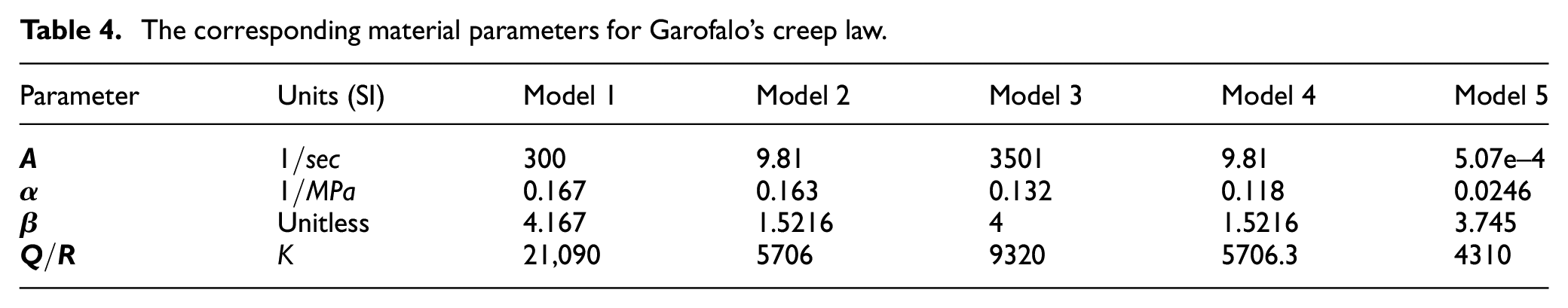
Using the previously described methodology, it is now possible to obtain the steady-state creep parameters of Garofalo’s law, outlined in Table 4.
The corresponding material parameters for Garofalo’s creep law.
Materials and methods
Test sample and DIC experiments
The test sample used in this paper is an insulated gate bipolar transistor (IGBT) Silicon chip installed on the surface of a printed circuit board (PCB) substrate, from Schwiezer electronic AG, Germany. Sintered Ag die attach (LTS – 338-28 from Heraus) was integrated between the chip and the PCB. The sintering process is fully described in Mathew et al.
35
The PCB substrate is
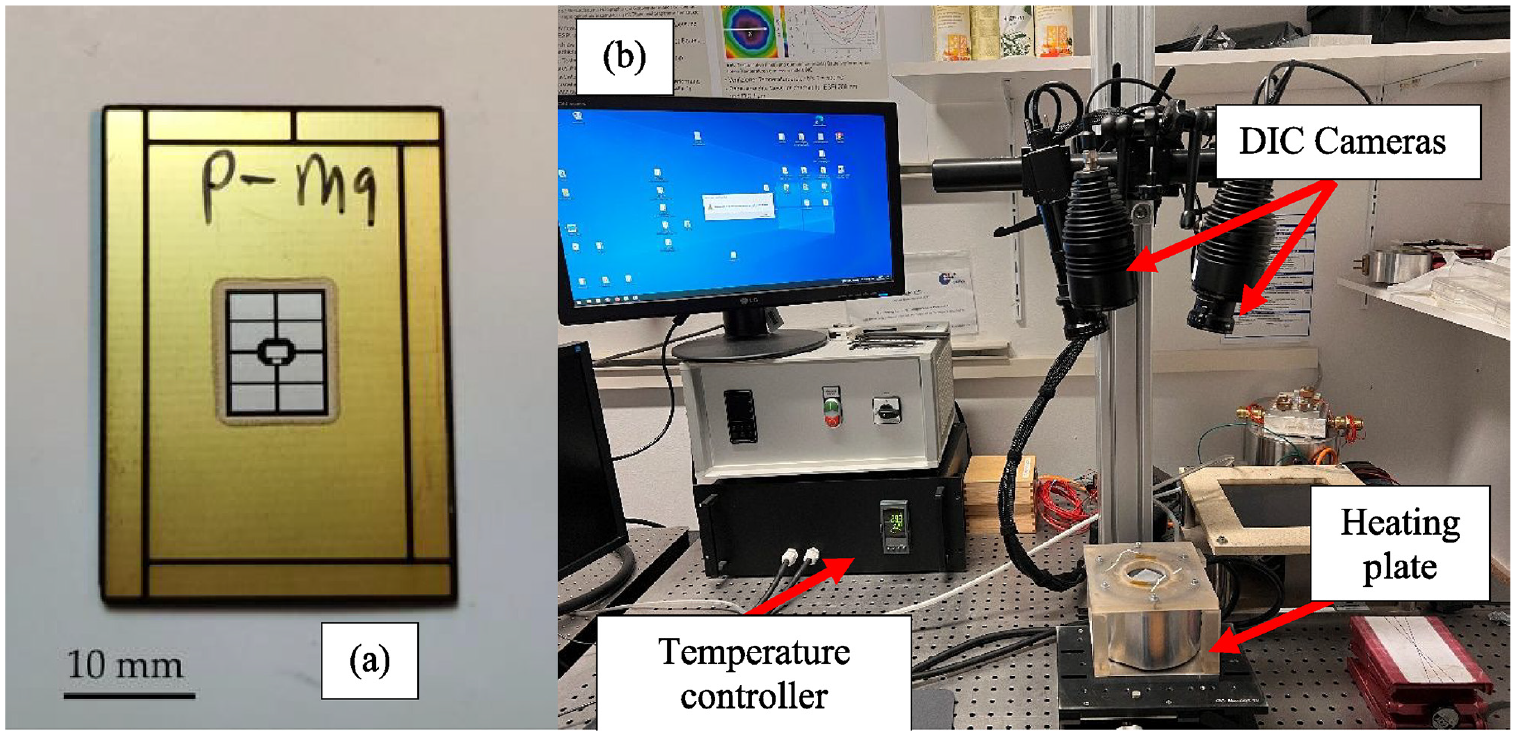
(a) Test sample and (b) experimental setup details.
In this work, digital image correlation (DIC) experiments are conducted to measure the transverse displacements of the IGBT chip due to temperature loading and passive heating. In this setup, Gesellschaft für Optische Messtechnik (GOM) system is used. This DIC system has two high-resolution stereoscopic optical cameras which are qualified to detected both absolute and relative displacement of the ship at all translational directions. During the experiment, the power module sample is heated up using an in-house fabricated heating plate in a perfectly vacuumed chamber to reduce the air convection above the sample for accurate measurement procedure. The sample is heated up at
Finite element analysis
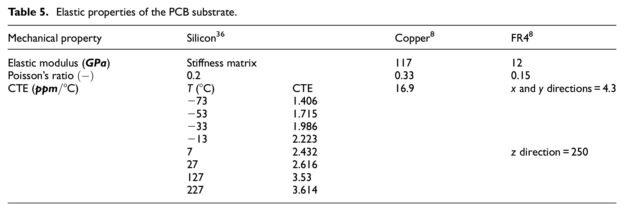
The three-dimensional finite element model of the current test sample is created and analyzed using ANSYS 2020R1 software. A special program using ANSYS Parametric Design language (APDL) is written to create the geometric model, define the material parameters and to execute the finite element analysis. For the mesh generation process, ANSYS SOLID185 element type is used. Additionally, the mesh topology was orchestrated to have finer properties at the location of stress localization. Utilizing the symmetry properties of the problem, one quarter of the sample was modeled resulting in 48,192 elements and 54,468 nodes model. The symmetry boundary conditions are imposed on the symmetry planes. To prevent rigid body motions of the model, it was fully constrained at the most-corner node. The elastic properties used for the PCB parts and for the IGBT chip, are listed in Table 5 and the FEA model is illustrated in Figure 2.
Elastic properties of the PCB substrate.
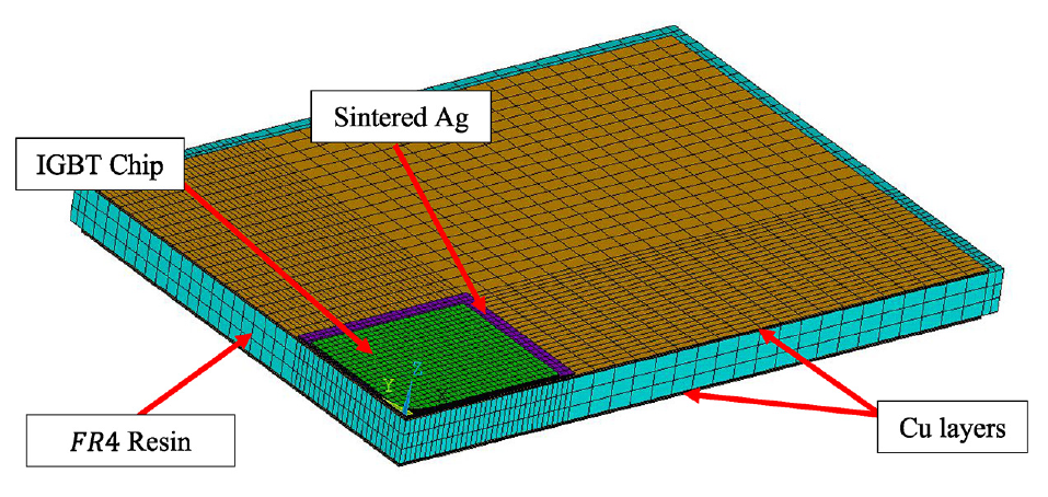
Finite element model for the IGBT chip mounted on the PCB substrate.
Results and discussions
Experimental results and FE model correlations
The temperature induced Si chip deformations measured by the DIC system are plotted in Figure 3 and compared to the FEA data of models with different Anand-based sintered Ag material parameters. The results show that in general the FE deformations compare very well with the experimentally measured data. However, there are difference in the behavior, that is, stiffness, between each material model. For example, sintered Ag FEA-model 2 is the most compliant (greatest deflections) and FEA-model 5 is with highest stiffness properties and smallest deformations.
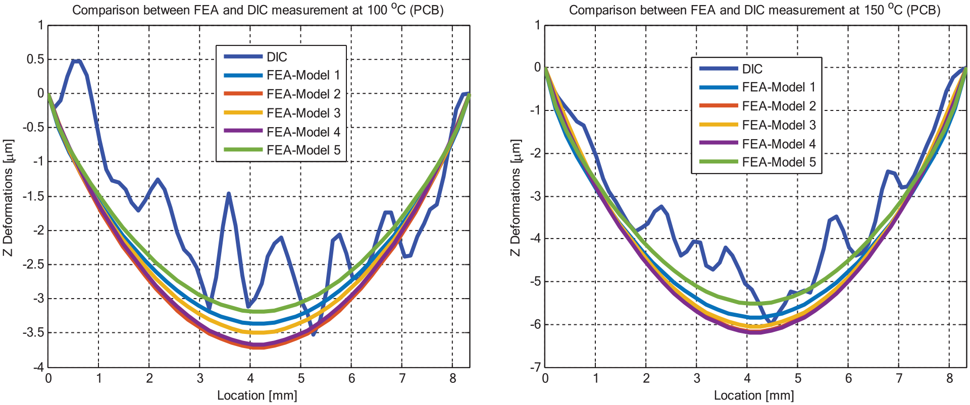
Comparison between the FEA displacements and DIC data at different temperatures using various Anand-based sintered silver material parameters.
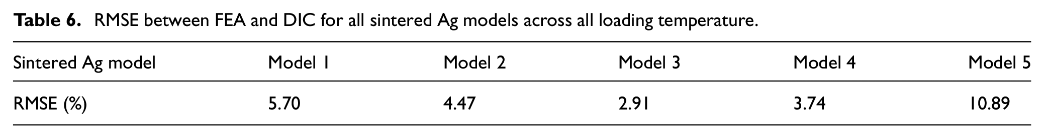
Additionally, the maximum displacements of the IGBT chip from FEA and experiments are extracted and compared, as shown in Figure 4(a). Also, the relative error between DIC and FEA maximum displacements is computed and depicted in Figure 4(b). Furthermore, the root mean square error RMSE is calculated for each sintered silver material system across both loading temperatures, as summarized in Table 6. As argued previously, the FE model, with various sintered silver material model, is in well-agreement with the measured displacements. However, the RMSE values show the error is approximately in the range of 3%–11%. Consequently, the response of the Anand-based sintered silver models can vary. Nevertheless, such variations cannot be easily quantified from the IGBT deflections response. Thus, further analysis is needed for better understanding and clearer quantification of such distinctions.
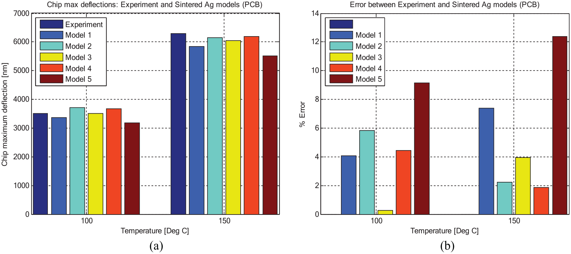
(a) Chip maximum displacements from experiments and FEA and (b) relative error between experiments and FEA chip maximum displacements at various loading temperatures.
RMSE between FEA and DIC for all sintered Ag models across all loading temperature.
Stress–strain relationships
To understand the discrepancies in the response of Anand models of the sintered Ag listed in Table 1, the FE models are executed to calculate the shear strain and shear stresses of the bonding layer due to temperature rise. A temperature loading with a profile of
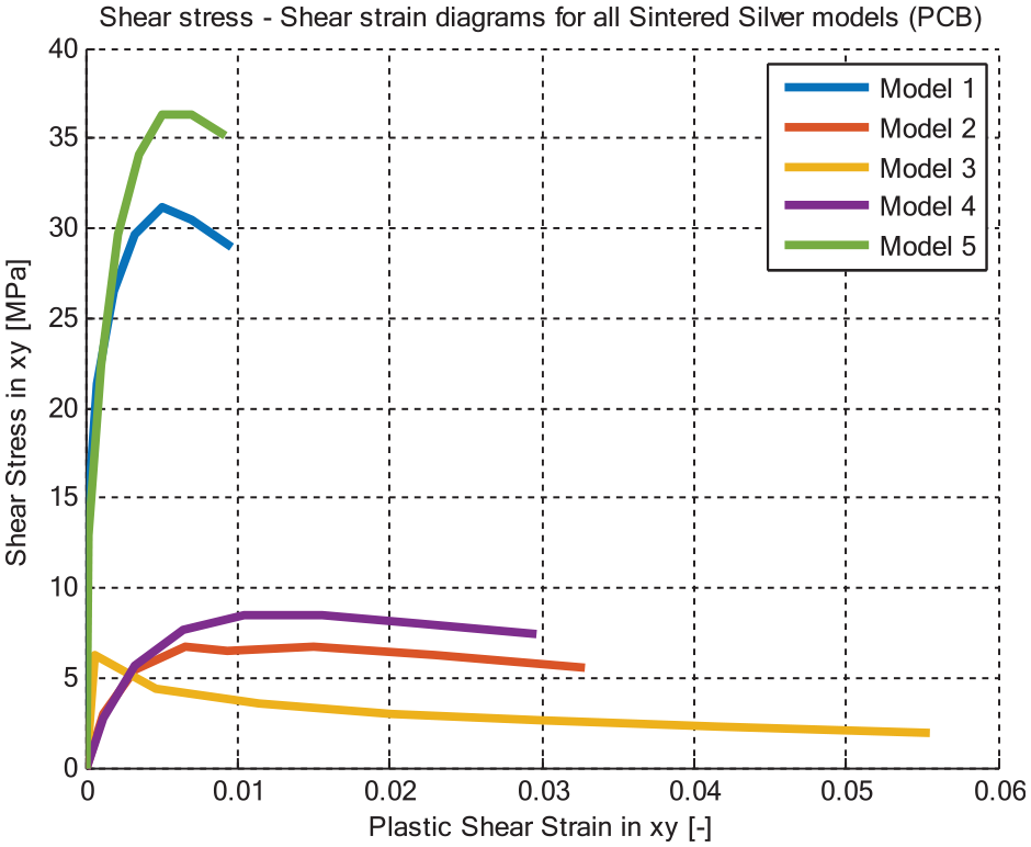
Shear stress–shear strain diagrams of the sintering layer using different Anand-based models.
For a closer look on the plastic strains, the maximum equivalent plastic strains of the sinter layer are plotted versus the loading temperature as shown in Figure 6. The simulation findings show that the maximum equivalent plastic strains of model 1 and model 5 are very small, and quite similar, which further strengthens the previously stated argument of which the response of these two particular Anand-based models is governed by elasticity properties. Whereas in model 3, as stated earlier, the equivalent plastic strains are higher due to the presence of viscoplasticity features of this specific model. In model 2 and model 4, the equivalent plastic strains are between the elasticity-driven and viscoplasticity-controlled curves. Consequently, steady-state creep response is anticipated.
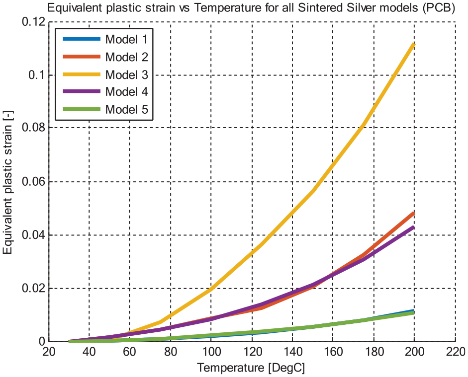
Equivalent plastic strain versus temperature of the sintering layer using different Anand-based models.
As discussed earlier, differences between various models are because of the variability in Anand model parameters. In fact, such differences in the material parameters are due to different sintering process parameters (pressure or stress level and sintering duration), sinter paste grain size, chemical additives, and the presence of voids in the sintered bond.
Thermomechanical analysis
To investigate the discrepancies between the previously discussed sintered Ag models and to discuss the effectiveness of Anand models versus Garofalo’s law, a 3-dimensional finite element thermomechanical analysis is conducted. In this study, five whole thermal cycles with profile of
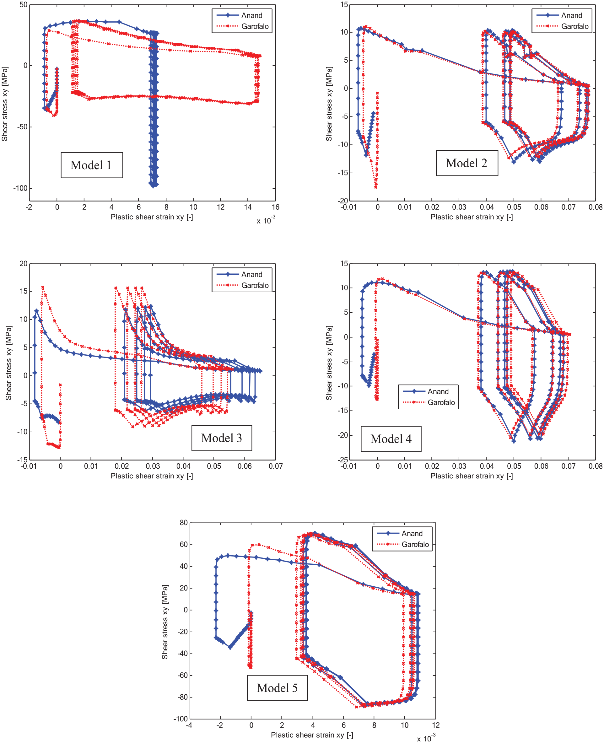
Hysteresis loop of the sintered Ag layer using different material and creep models.
Generally, it is observable that the hysteresis loops can vary between the Anand-based and the steady-state creep-based loops. Such alterations differ from very minor to relatively important. For instance, the Anand-based loop of model 1, does not show any loop area, that is, no sintered Ag bond damage, and that is due to previously presented statement of that model 1 is largely dominated by elasticity. However, for the Garofalo-based loop data, the area of the hysteresis loop is knowingly greater and thus greater bonding layer damage. For sintered Ag model 2 and model 4, the hysteresis loops from both secondary creep and viscoplasticity-based model are practically identical. This additionally demonstrates the previous argument of that these specific models (2 and 4) are typically driven by secondary creep behavior. This is because of the unity value of (
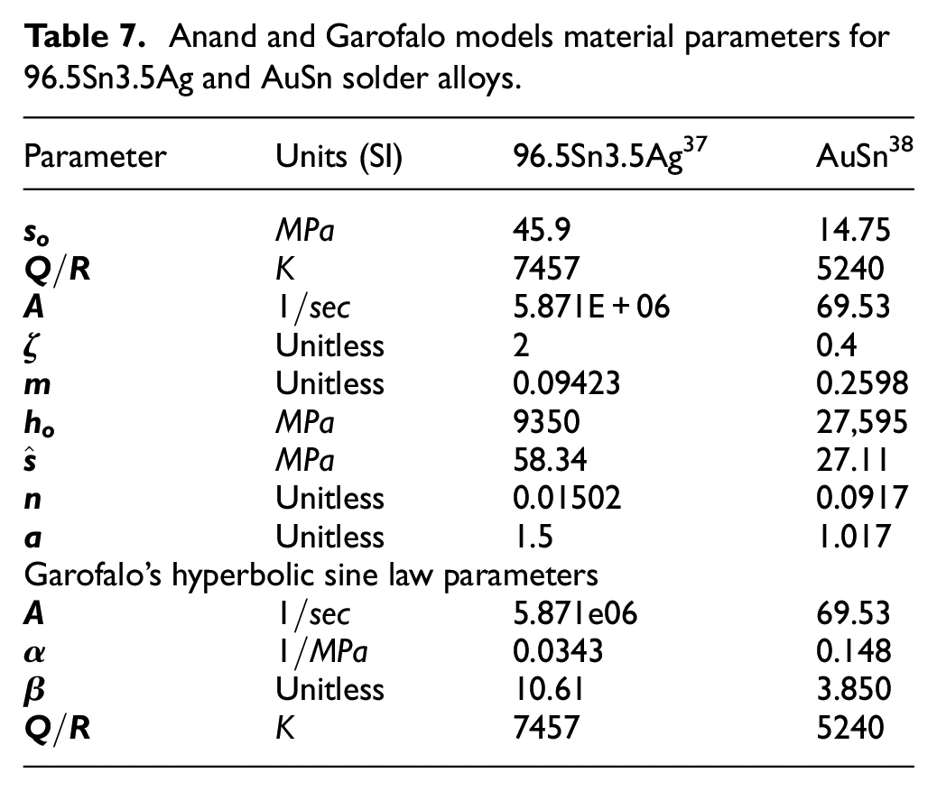
In addition to the sintered silver bonds, this paper studies the effect of the creep constitutive law on the response of two other common alloys that usually used as die attachments in power modules; Tin-Silver (96.5Sn3.5Ag) and Gold-Tin (AuSn) alloys. The mechanical parameters, including Anand constants, of the 96.5Sn3.5Ag and AuSn are extracted from literature sources. Using the previously described process, Garofalo’s law constants are also estimated. Material data of both alloys are detailly listed in Table 7.
Anand and Garofalo models material parameters for 96.5Sn3.5Ag and AuSn solder alloys.
Thermomechanical simulations, according to the profile discussed earlier, are executed and the resultant hysteresis loops of both solder material are plotted in Figure 8.
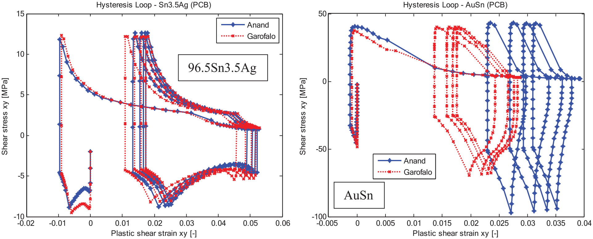
Hysteresis loop of the 96.5Sn3.5Ag and AuSn solders using different creep laws.
The results of 96.5Sn3.5Ag show that the hysteresis loop of Anand and Garofalo models are very similar. This is because of the very small the value of (
In summary, most of the literature-available Anand models of various alloys and materials used as die attachments of power electronics can be fairly approximated by steady-state creep laws. However, this has to be carefully ensured.
Discussions on the lifetime analysis of Sintered Ag
In the lifetime calculations of electronics, there are two key models; strain-based and energy-based fatigue models. Coffin-Manson’s rule is a common example of the strain-based type models and Darveaux’s model is a widely accepted energy-based law. In Coffin-Manson’s and Darveaux’s laws, the equivalent plastic strain (EPS) and the inelastic strain energy density are used (SED), respectively, as the lifetime evaluation metric. Therefore, the current paper discusses these two famous fatigue life estimation models for the sintered silver bonds in power modules.
From the previously executed thermomechanical simulations, the values EPS versus cycle time and the EPS per cycle versus cycle number are presented in Figure 9. The results are based on Anand (solid lines) and Garofalo (dotted lines) models.
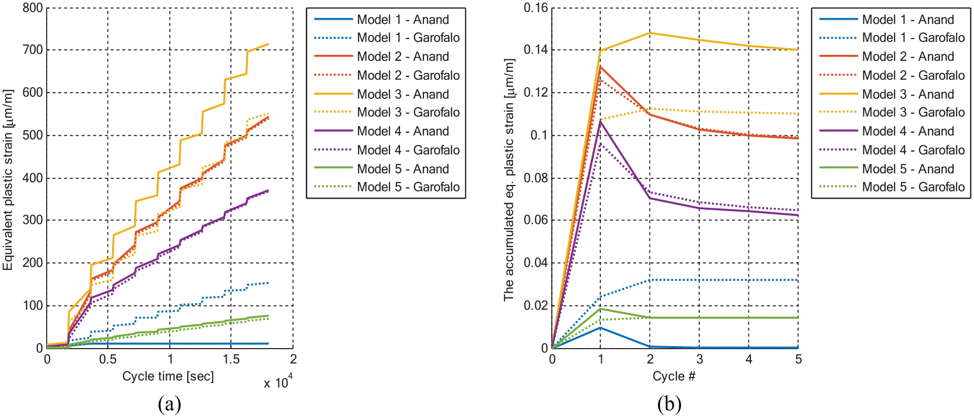
(a) Cyclic equivalent plastic strains and (b) the accumulated equivalent plastic strains of the die attachment layer.
The results show that, for models 2, 4, and 5, the EPS values are generally the same in creep models. Yet, in model 3, the plastic strains of Garofalo’s creep are considerably lower than those of Anand’s model. While model 1, the strain values from the secondary creep law are lower than that of the viscoplasticity model. For the EPS per cycle results, models 2, 4, and 5 strains show comparable behavior from both creep laws. Again, because
One last conclusion here is that the values of EPS can significantly vary from model parameters to one another, in addition to the creep constitutive model implemented throughout the FEA simulations. As a result, utmost care must be taken while developing strain-based fatigue life models or when using literature readily available models to predict the fatigue life of sintered silver bonds of power electronics. Otherwise, disastrous predictions and/or fatigue life estimations could be achieved.
As mentioned previously, Darveaux’s model is a widely considered energy-based model for assessing fatigue life of sintered silver bonds. In this law, the crack initiation and crack propagation rate in sintered Ag layer are function of the inelastic strain energy density (SED). In theory, the inelastic SED, often indicated as the plastic work, is the area under the inelastic, that is, plastic, portion of the stress-strain chart of a given material and it is measured in the units of energy per volume.
The inelastic SED versus cyclic time and the inelastic SED per cycle versus cycle time are plotted in Figure 10, as extracted from the formerly performed thermomechanical simulations. The results show that the values of the inelastic SED are greatly reliant on the sintered silver material parameters. Nevertheless, they are not substantially influenced by the creep constitutive model used in the simulation, except for model 1. Accordingly, extreme care must be carried during the process of creating energy-based lifetime evaluation models of the sintered silver or when predicting the fatigue life of such bonds utilizing the literature-existing lifetime models. Otherwise, inaccurate fatigue life estimations and/or predictions could be reached.
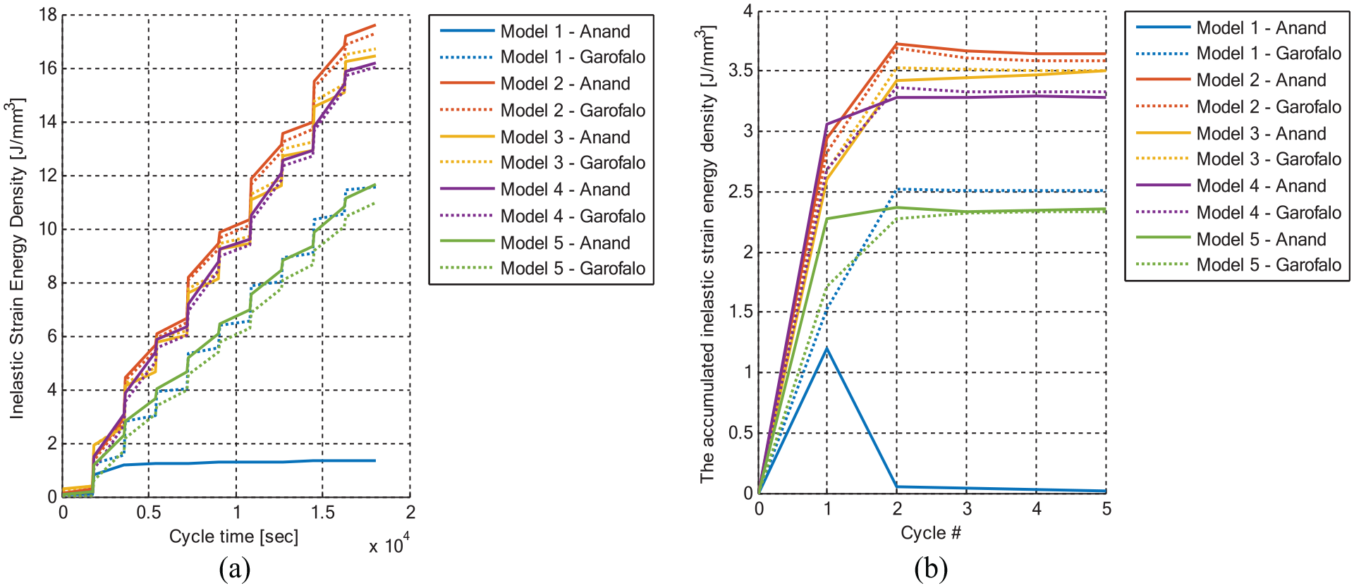
(a) Cyclic inelastic strain energy density and (b) the accumulated inelastic strain energy density of the die attachment layer.
Furthermore, it is essential to emphasize here that the present research is performed for one particular arrangement of IGBT silicon chip on a comparatively compliant substrate (PCB). Appropriately, the use of other substrates and/or other IGBT chip structures may possibly lead to distinct results. Therefore, this must also have to be taken care of during the lifetime assessment examinations.
Additionally, it is not only the numerical modeling of the properties that varies. In fact, all of the published creep deformation data and models reveal considerably different real, that is, factual, properties of the sintered silver. Such differences are a result of different sintering process parameters (pressure or stress level and sintering duration), sinter paste grain size, chemical additives and various degrees of densification or porosity levels, that is, voids, in the sintering bonds. 39 Therefore, it is strongly advisable to measure the mechanical properties of sintered silver individually or by using more sophisticated techniques like nanoindentation for more reliable measurements.40,41
Subsequently, it is extremely critical to control as many as thinkable of the parameters involved in the lifetime assessment process of sintered Ag die bonds for most accurate thermal fatigue life estimations, including but not limited to creep constitutive model and material parameters, geometries, and other characteristics of the power electronic module.
Conclusions and recommendation for future work
Conclusions
This paper used thorough and detailed three-dimensional finite element simulations to examine the influence of the material model parameters and the creep constitutive laws of the sintered silver on the thermal fatigue life evaluations and predictions of power modules. In this numerical investigation, several creep constitutive models, including Anand viscoplasticity model and Garofalo’s hyperbolic sine law, in addition to various literature-based sintered silver models were examined. The FE models were first validated with digital image correlation thermally caused deformation data of the silicon chip. The results showed that the silver-based bond stresses, plastic strains, and plastic work are greatly influenced by the material constants as well as by the creep constitutive models. Therefore, the thermal lifetime assessment and projections. As a result, this paper provided important insights toward the proper use and measurement of such material models for the lifetime evaluations of sintered silver die bonds in the power modules.
Recommendations for future work
It is proven in this paper that various sintering process variables, that is, sintering temperature, time and pressure, and bond characteristics, like grain size and voids density, could lead to significant differences in the mechanical response of the die attach layer. During the analysis, this was demonstrated in the variability in the material model parameters like the elastic modulus and Anand model parameters. Therefore, the present study highly recommends future works that quantifies the effect of each process and bond factor on the material constants and then use the finite element simulations to evaluate the plastic strains as well as inelastic strain energy densities of the die bond for the fatigue life evaluations. Finally, such studies could lead to the understanding of the effect of the sintering process variables on the fatigue life expectations of the sintered silver die attachments.
Footnotes
Acknowledgements
The authors also desire to acknowledge Mr. Arben Qelibari and Mr. Haosu Huai from the IMTEK – University of Freiburg for their precious help during the DIC measurements and sample preparations.
Declaration of conflicting interests
The author(s) declared no potential conflicts of interest with respect to the research, authorship, and/or publication of this article.
Funding
The author(s) disclosed receipt of the following financial support for the research, authorship, and/or publication of this article: This work is funded by the German Research Foundation (Deutsche Forschungsgemeinschaft – DFG) under the grant WI 1987/7-1.