
Abstract
The conditions for slip within a contact and at the corner, together with separation conditions, are presented in a general sense and applied to two example finite complete contact problems. These conditions can be found directly from the signs of the relevant stress intensity factors. Furthermore, a new bound on the validity of the asymptotic solution is found and then applied to find a solution relating to separation conditions. Finally, this new bound is used to identify and classify cases in which a region of mode II dominance is seen from purely geometric considerations.
Introduction
Complete contacts are those in which the front (contacting) faces of the bodies being pressed together have the same shape in the unloaded state, that is, they ‘conform’, and the extent of the contact is defined by a discontinuity in the gradient of the profile, as exemplified by the rectangular block-on-half-plane arrangement shown in Figure 1. They have the property that the contact size is independent of the load carried and that a stress singularity will usually arise at the edges of the contact. Practically occurring contacts which are of this general form include splines, for example, in certain car transmissions and in the split shafts of a gas turbine.
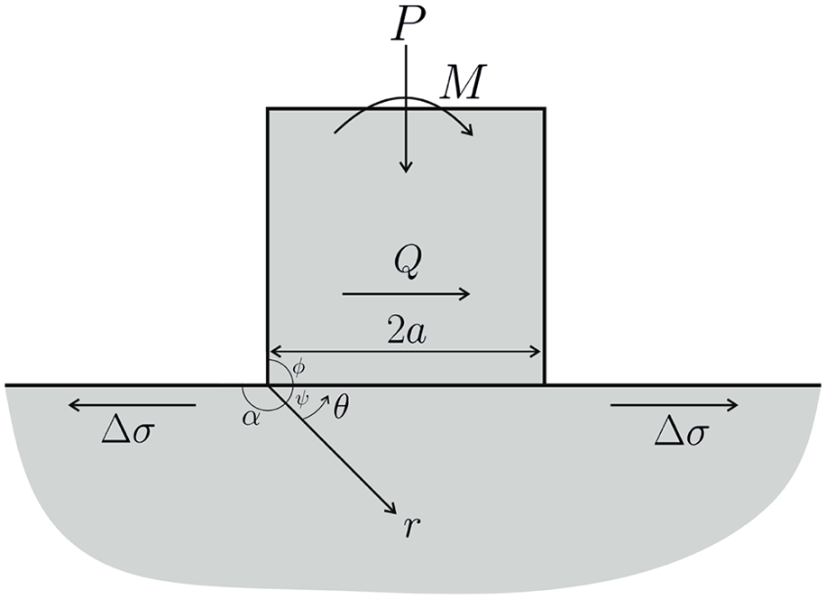
Rectangular block resting on a half-plane subject to four external loads.
The objective of the analysis presented here is to quantify the conditions for ensuring that the contact edges are stuck so that fretting damage is avoided, although this does leave the attendant risk of a notch-type failure. We shall assume that the block and the half-plane are made from the same material and also that the interface is, indeed, straight, as sketched, but note that the results to be found would apply equally well to a circular cylinder resting in a conforming groove, provided that the line of the interface was accounted for correctly.
A full analysis of the problem, including incorporating the presence of all features, calls for a finite element (FE) analysis, and indeed, the FE analysis must be used to calibrate the external loads to stress intensity factors to be defined, but our objective is to learn as much as possible about the properties of the contact from an analysis of the half-plane and contact corner modelled together, as a monolith, and use Williams’ analysis 1 of a wedge as our starting point. The use of this classic asymptotic form, appropriate when the observation point is much nearer to the corner than any other features, adds considerable precision to our understanding of the local stress field.
This idea is one which we have used before. It enables the coefficient of friction needed to attain a fully stuck contact edge 2 to be determined. But in that analysis only the dominant term in an eigenfunction expansion was used, and the question arises of what happens when we move slightly inwards from the edge: Is the coefficient of friction needed to achieve stick at the edge also sufficient to attain stick in the rest of the neighbourhood? We answer that question, here, together with looking at further forms of excitation of the local stress field.
One of the main topics of practical analysis in this laboratory is the study of fretting and fretting fatigue, and in pursuing these, we note that there are normally four sets of external loads which are relevant in describing the local contact edge stress field (Figure 1), namely, the normal load, P, the shear force,
Formulation
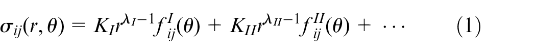
It is initially assumed that the two contacting bodies are in intimate contact everywhere, and fully adhered, giving a monolithic domain. We zoom in on the contact (wedge) corner. At the time of the initial consideration of this class of problem, we would write down the state of stress in the neighbourhood of the wedge (contact) corner 1 in the form
where
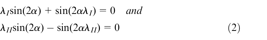
where
and
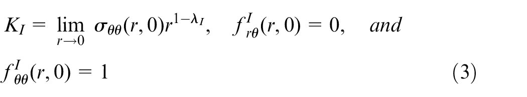
Before introducing an alternative representation of this solution, we will consider the physical requirements for the solution to be developed to be appropriate when applied to contact problems. These are (a) that the two bodies be in intimate contact, implied by
For the time being, focus attention wholly on the square block (Figure 1) so that
So equation (1) may be re-written as
This form is extremely useful for studying notch-corner plasticity
3
and highlights that
A remark on separation
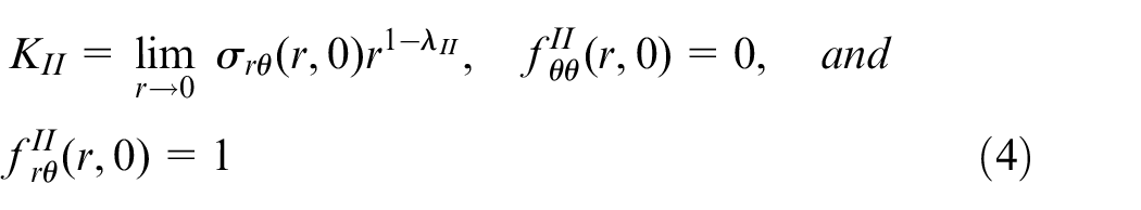
It is well known that we may always find a point, sufficiently close to the corner, where the stress state is totally dominated by the mode I term. Its sign is determined by the sign of the stress intensity factor
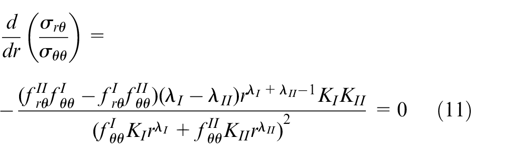
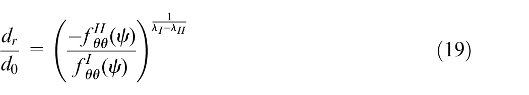
We now suppose that the edge of the contact is intimately closed but consider the possibility of lift-off at a point within the body, according to the asymptotic results. For this to occur, and to be observable within the asymptote, we require a turning point in the equation

found by
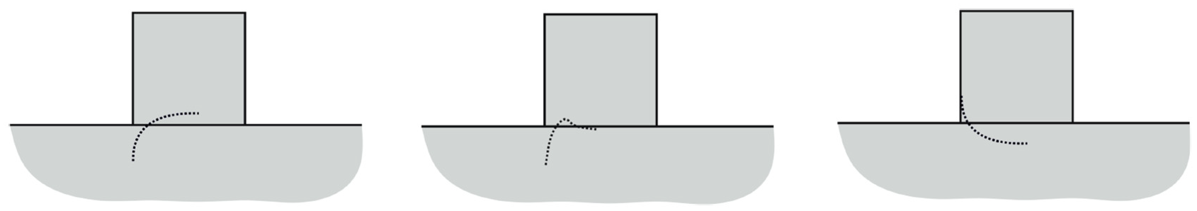
Sketch of different possible shapes for
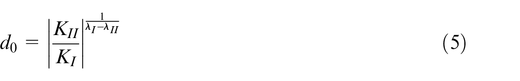
The location of this point is given by
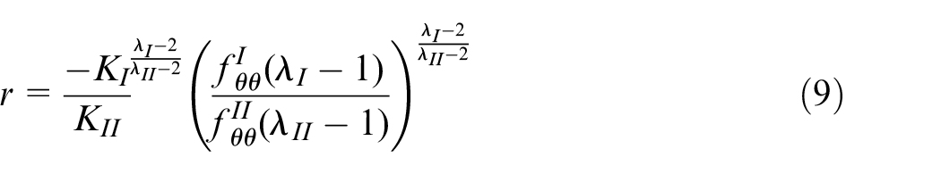
Note that the quantity within parentheses depends only on
Application to the 90° block
Retaining a focus on the square block resting on a half-plane, we aim to improve on and refine the conditions set out by Churchman and Hills 4 for separation at the edge of the contact and within the body, as far as it is possible with only asymptotic considerations.
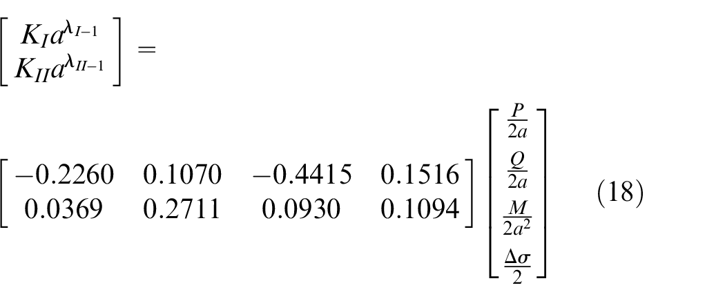
To do this, we use an FE analysis of the problem to calibrate the external loading with the stress intensity factors. This is done by modelling the problems and then applying each of the four external loads individually. The stresses along the angle bisector are then found from FE, and the limits are taken as described above in equations (3) and (4). The results of this for the square block are shown in equation (10). However, we will first concentrate on excitation by only a normal force
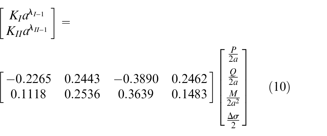
From the calibration, we see that the value of
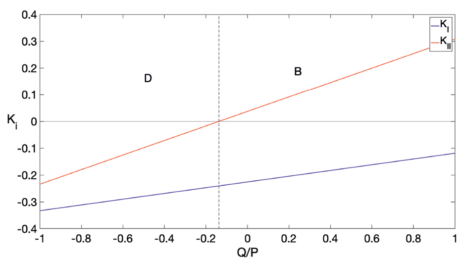
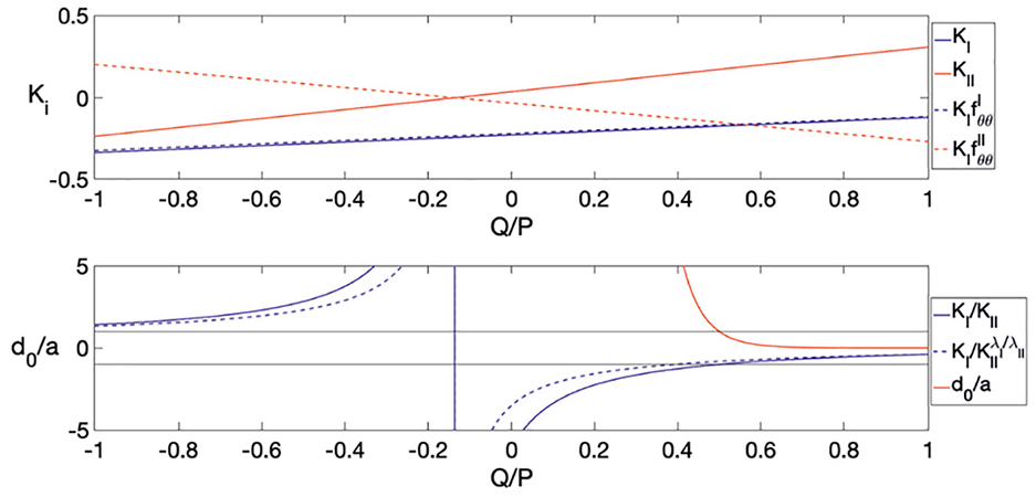
We now intend to see how the location of the turning point (equation (9)) changes with changes in normal and shear load. We can see from Figure 3(a) that the ratio
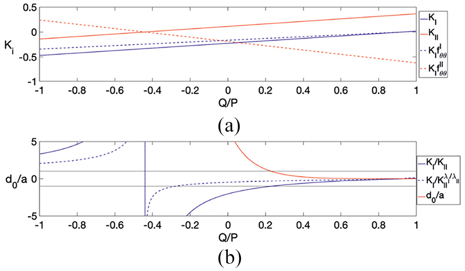
The variation of stress intensity factors: (a) relevant constants and (b) with varying
The positive value of the ratio
So, for the 90° block, at least, we cannot improve on the statement presented by Churchman by the use of a two-term solution. We conclude that lift-off only occurs in the near edge when
Slip
As laid out at the start of this article, one of the objectives of this analysis is to determine the conditions required for the corners of the contact to remain stuck to avoid fretting damage. Equally important is ensuring that there is no region of slip within the body, which would equally lead to fretting damage.
Recall from Hills and Dini
3
that the corner will slip for a sufficiently low coefficient of friction. Hence, we must determine under what conditions slip will occur within the body, and within the asymptote, or at the corner. As already discussed in section ‘A remark on separation’, there are conditions under which we get lift-off at the corners of the block. This will necessarily lead to some partial slip. We deduce this because the direct traction
The turning point
To determine whether an interior point is the point of first slip, let us first consider the ratio
The turning point can be found by
Provided that the denominator is non-zero, we may first deduce that we can in fact solve the equation

Now set
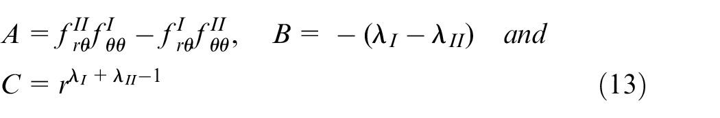
So equation (12) becomes

From Williams’ solution, we have
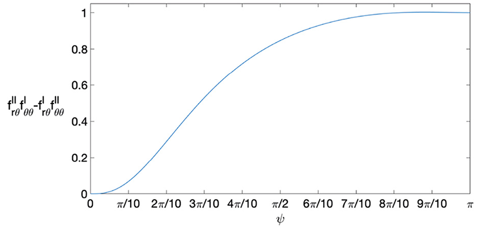
Value of
So a turning point can exist only if
For all other cases,
Recall that
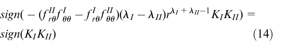

Hence
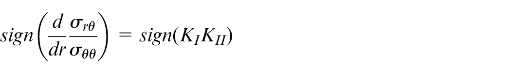
whenever the gradient is determinable.
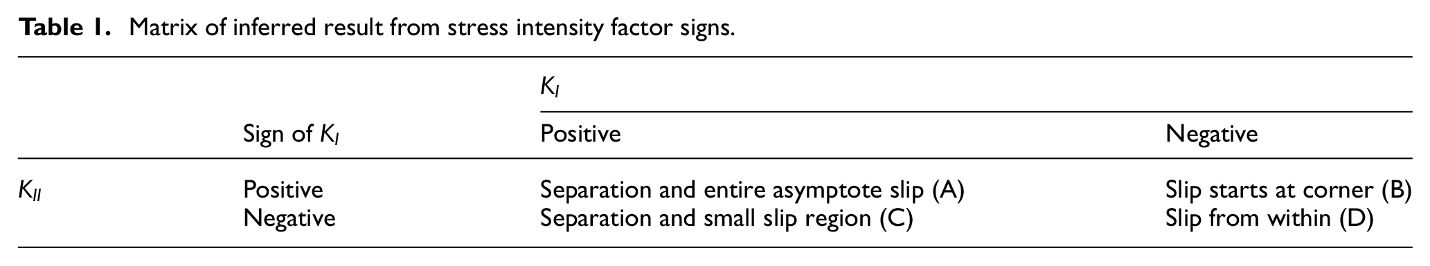
The results here are interesting. We know that if
Matrix of inferred result from stress intensity factor signs.
Application to the 90° block
Returning focus to the 90° block, we may distinguish the regions of the load space where each of these forms of behaviour occurs. The results of this analysis are shown in Figure 5. The letters shown correspond to those defined in Table 1. Note that, under these loading conditions, there is no region in which
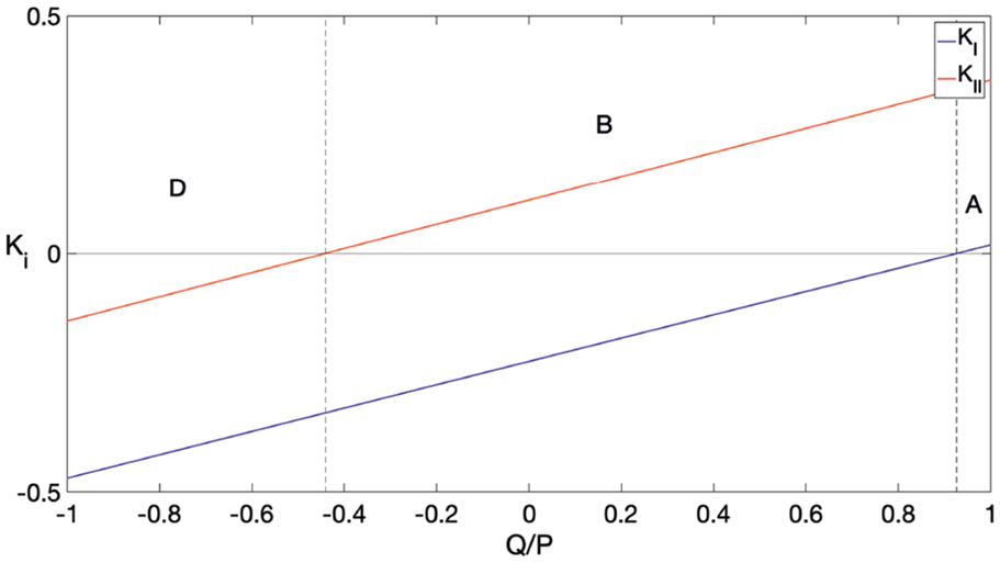
Plot showing the regions of behaviour for the 90° block.
Further forms of loading
So far, we have considered excitation only by a normal and shearing force, and we have assumed that these are not sufficient to cause sliding, that is,
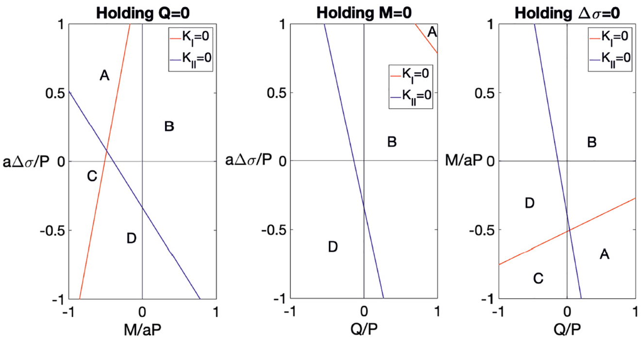
We can divide the load space to characterise behaviour under general loading as we did with just two loading types. Figure 6 shows the results of these where, in each, one of the loading methods is not excited. Consequently, we can see the load regions where each of these types of behaviour occurs; again the letters refer to those in Table 1.
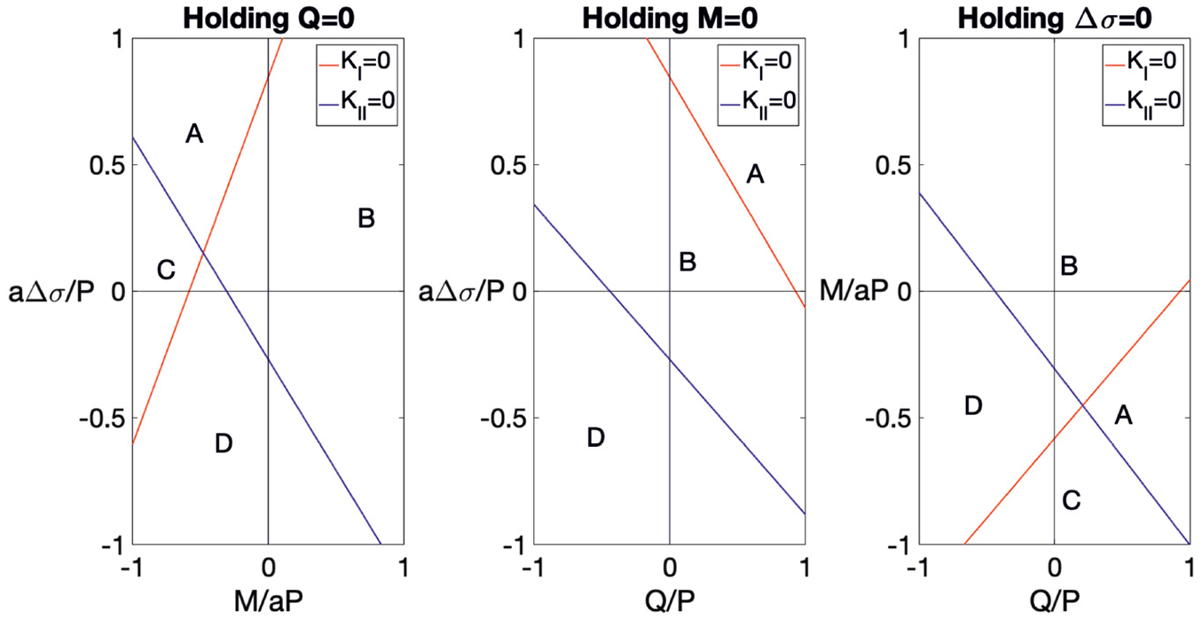
Characterisation of regions of the four-method load space (see Table 1).
A further bound on asymptotic validity
From section ‘A remark on separation’, we can see that, provided that the corner is in intimate contact, the whole interface, within the region which can be approximated by the asymptotic solution, must remain in intimate contact – in other words, throughout the region of asymptotic validity,
So, we solve the equation evaluated on

to find the value of
So we can state, using this bound, that for the stresses at a point
Consideration of other angles
So far, throughout this article, our examples have been limited to a square block resting on half-plane; however, it is not necessary to do this, and the general results presented are equally applicable to any complete contact. An obvious extension is to take the internal angle of the block as a parameter,
Use of this calibration leads us to conclude that under no combination of pure
Plot showing the regions of behaviour for the 143° block.
Characterisation of slip behaviours of the 143° block in four load space.
The variation of stress intensity factors and resultant constants with varying
Slip consideration can also be made, and the letters shown in Figures 7 and 8 relate again to Table 1, which is still applicable here. Common throughout all of these is that, for moderate loading and largely for positive valued loading (as defined by convention in Figure 1), slip will originate from the corner, regions marked ‘B’, and hence the conditions necessary to prevent slip at the corner are sufficient to prevent interfacial slip throughout the interface.
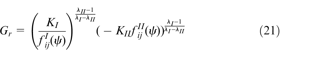
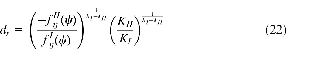
A bound on the existence of mode II–dominated regions
Throughout this analysis, we have utilised a two-term analysis. We have already seen that it is always possible to find a point where the state of stress is dominated by the first term in our expansion. However, we now ask whether the same can be said for the second term. We already know that these points, should they exist, would be at a point
Plotting this, we find that, as shown in Figure 10, the value
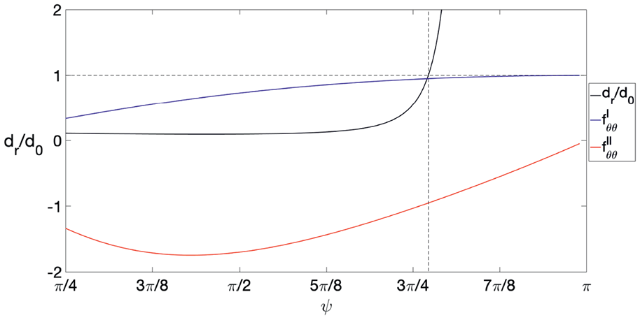
The value of the ratio
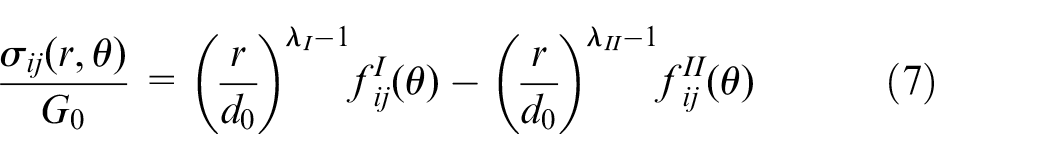
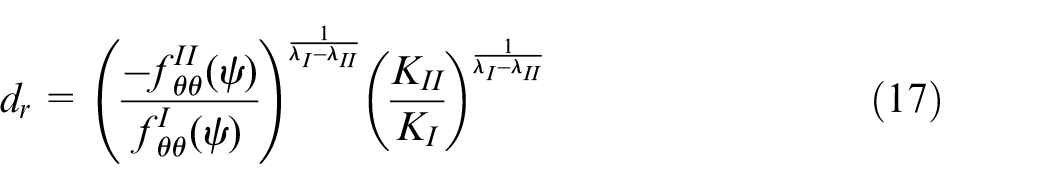
A new normalised form of the solution
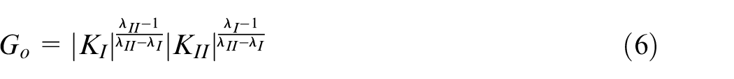
Finally, we may use
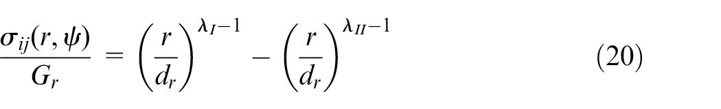
where
Conclusion
The objective of this analysis was to gain extra information about the form of solution from a two-term asymptotic consideration, compared to that found using a single-term approximation. This has proven to be a difficult task. However, several general conclusions can be drawn from the work presented.
A set of conditions which categorise slip behaviour solely from the signs of the relevant stress intensity factors have been devised. We find that in cases with positive
Furthermore, a bound on the validity of asymptotic solutions was established, and from this, a new normalisation of Williams’ solution is possible. Also resulting is a bound on indenter angle necessary for a mode II dominant region to be visible by asymptotic methods.
Footnotes
Appendix 1
Appendix 2
Acknowledgements
Both authors thank Rolls-Royce plc and the Engineering and Physical Sciences Research Council (EPSRC) for the support under the Prosperity Partnership Grant.
Declaration of conflicting interests
The author(s) declared no potential conflicts of interest with respect to the research, authorship, and/or publication of this article.
Funding
The author(s) disclosed receipt of the following financial support for the research, authorship, and/or publication of this article: This work was supported by the Prosperity Partnership Grant ‘Cornerstone: Mechanical Engineering Science to Enable Aero Propulsion Futures’ (Grant Ref: EP/R004951/1).