
Abstract
The offset between the hole and the centre of the strain-gage rosette is unavoidable, although usually small, in the hole-drilling technique for residual stress evaluation. In this article, we revised the integral method described in the ASTM E837 standard and we recalculated the calibration coefficients. The integral method was then extended by taking into account the two eccentricity components, and a more general procedure was proposed including the first-order correction. A numerical validation analysis was used to consolidate the procedure and evaluate the residual error after implementing the correction. The values of this error resulted limited to a few percentage points, even for eccentricities larger than the usual experimental values. The narrow eccentricity limit claimed by the standard, to keep the maximum error lower than 10%, can now be considered extended by approximately a factor of 10, after implementing the proposed correcting procedure, proving that the effect of the eccentricity is mainly linear within a relatively large range.
Keywords
Introduction
Residual stresses can significantly influence the strength of mechanical components, especially under cyclic fatigue loading.
1
There are several experimental techniques for measuring residual stresses.
2
These include mechanical methods (destructive or semi-destructive) based on cuttings or local material removals to relieve the embedded residual stresses, such as the contour method,
3
the ring core method4–6 and other specific approaches adapted to the geometry of the components investigated,7–11 or also combining the hole-drilling method with the indentation.
12
After the material has been removed, a back calculation is required to obtain the residual stress distribution that has been relaxed.13,14 The hole-drilling method is the most popular and widely investigated.15,16 Its hardware is easily implemented, it is relatively inexpensive and it directly provides the stresses at a point; specifically, it averages the stress on the small volume of the removed material. Hole-drilling can be performed by measuring the entire field of the relaxed deformation with optical methods
17
both on the isotropic elastic materials, namely, steel or other metallic alloys, and on the orthotropic materials such as composite plates.
18
However, the hole-drilling technique is usually performed just with a strain-gage rosette to measure the relaxed strains in the near area of the drilled hole. There are many application examples of this technique such as large components showing a flat (or almost flat) surface,
19
deep rolled or shot peened flat specimens,20,21 and recently even on coated surfaces.22–25 The usual rosette for hole-drilling has three grids angularly placed at
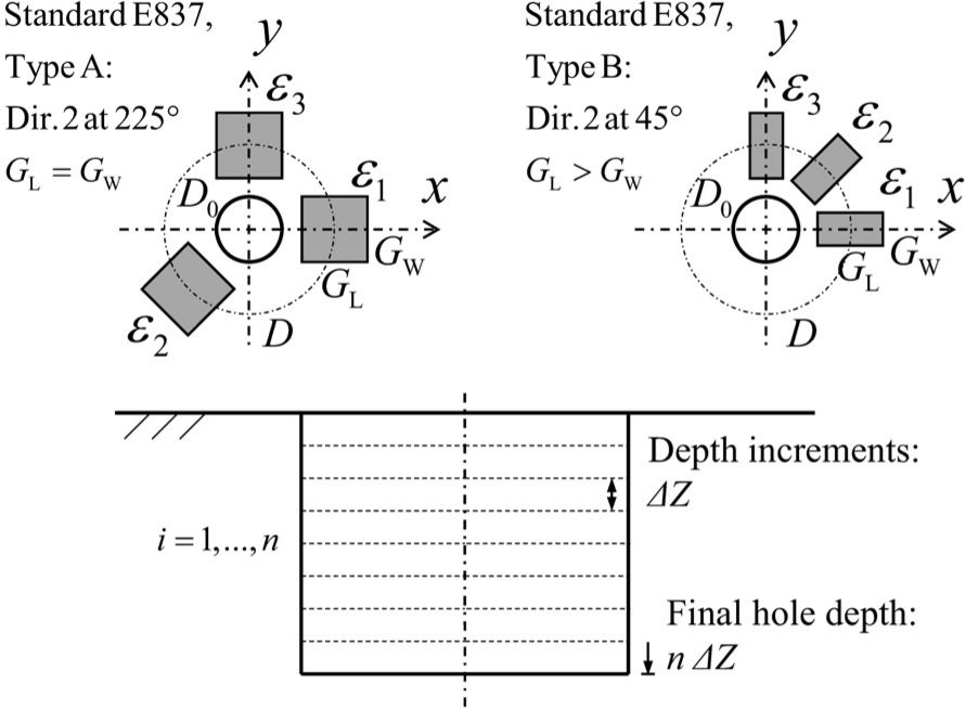
Hole-drilling method with type A and type B rosettes according to the CCW numbering system.
After having measured and recorded the relaxed strains, the integral method is usually considered for the calculation of the residual stress distributions. The integral method was initially proposed by Schajer26,27 and recently has been widely used and also conformed to specific cases, such as medium thick plates 28 and thin plates, 29 as well as being extended to optical methods. 30 The ASTM E837-13a standard 31 codifies the hole-drilling integral method, with a strain-gage rosette. The calculation proposed takes into account that a variable distribution can be obtained, where the stresses are assumed to be piecewise constant over each hole depth increment. Then, the standard reports the calibration coefficients (dimensionless and in matrix format) which depend only on the geometry, thus enabling the residual stresses from the measured relaxed strains to be calculated.
Error analysis is crucial for any residual stress experimental technique; indeed, we recently proposed a bending test rig for providing a validation concurrently with the measure itself.32,33 Many investigations can be cited from the literature considering different sources of errors for the hole-drilling technique. The strain measure uncertainty, which is the most important,
34
can be reduced to some extent by following the regularization procedure proposed by Schajer
35
and then implemented in the ASTM E837 starting from the 2008 issue. Another source of error affecting the hole-drilling measures is the plasticity induced by the drilling, for which we proposed a correction in a previous study.36,37 The shape, radius and the position of the hole are also the reasons for experimental uncertainty. The flatness of the bottom surface was questioned by Scafidi et al.
38
and then by Nau and Scholtes,
39
while the problem of eccentricity was initially investigated analytically by Ajovalasit
40
for a thin workpiece where a through-hole (plane stress) assumption can be used. More recently, Beghini et al.41,42 introduced the influence function approach, for a blind hole in a thick workpiece. The strain field was computed starting from a database of numerical solutions, implementing a specific geometric configuration in which the components of eccentricity are merely introduced as the geometry parameters rather than being considered as a source of error. The integral method according to the ASTM E837 standard enables the residual stress calculation to be easily implemented, but the presence of hole eccentricity is a limitation. The standard requires a nearly perfect concentricity between the hole and the rosette. The prescribed maximum allowable eccentricity value is
Integral method
Within the concentricity assumption, the axial-symmetric geometry allows a decoupling between the components of stress with respect to the corresponding relaxed strains. The residual stresses are related to the relaxed strains according to the general relationship introduced by Schajer26,27
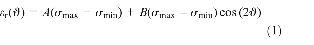
where
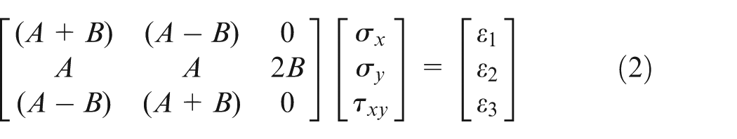
in which 1, 2 and 3 are the three grid directions:
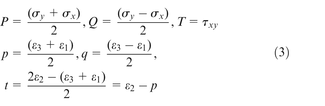
In the second of equation (3), the component of strain t has been intentionally defined with the opposite sign with respect to the ASTM standard in order to have sign consistency between the shear stress
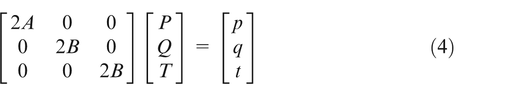
This linear dependence between the residual stresses and the relaxed strains is a consequence of the elasticity behaviour of the material. Therefore, equation (4) can be rewritten with the explicit dependence of Young’s modulus E and also the negative sign of the two coefficients can be emphasized
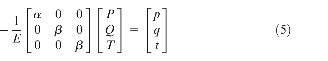
where
The stress–strain relation of equation (5) only considers a single value of the stress state, which is assumed to be uniform along the depth. In the specific case of small thickness, plane stress, this relationship can be further developed by making explicit the dependence on the Poisson’s ratio
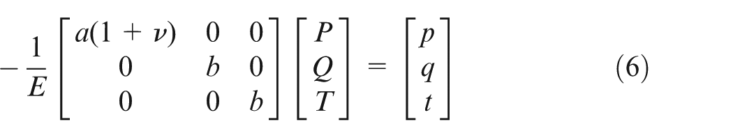
where, according to equation (5),
A major development of the method is the introduction of a possible non-uniform distribution, in which the components of stress are introduced as uniform stepwise. There are thus three independent components for each increment of the hole. In this case, the scalars
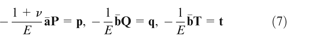
Vectors
The integral method with variable stress distribution, which is summarized in equation (7), just requires the axial symmetry of the removed material shape and the orientation of the measurement grids according to the
Extension of the integral method to the eccentricity
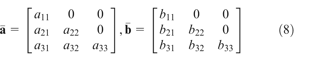
When an eccentricity between the drilled hole and the rosette is introduced, even if small, equation (1) is no longer valid. Therefore, it is not possible to decouple the
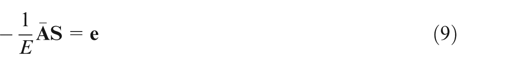
where
The coefficients
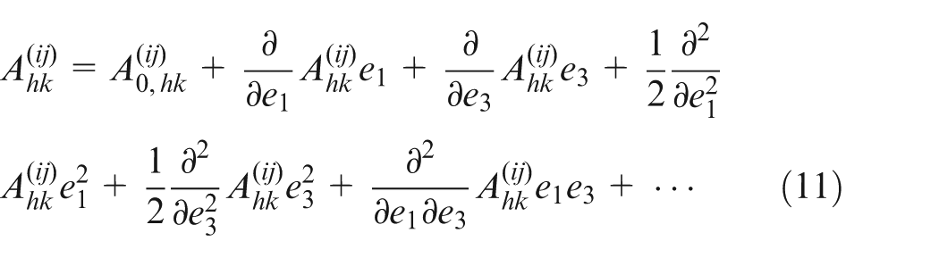
In equation (11), the two eccentricity components
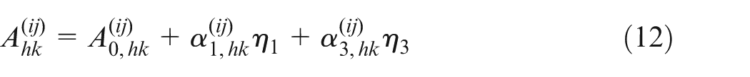
where the dimensionless derivative coefficients and the eccentricity components are
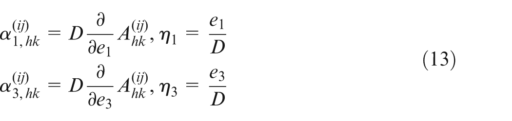
The coefficients
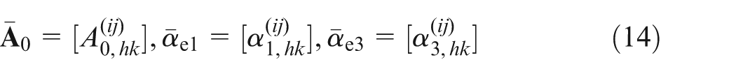
and finally, matrix

Clearly, the availability of matrix
Being the stress component decoupling not used, a three-grid rosette with
Symmetry properties
As shown in Figure 2, the hole eccentricity affects the sensitivity of the grids. When the eccentricity is along the direction of the grid, the sensitivity is higher if the hole is closer to the grid; thus, the absolute value of the measured relaxed strain is larger. On the other hand, if the eccentricity displacement is transversal, a portion of the grid has a higher sensitivity, while the other side has a lower sensitivity and this implies, for symmetry, that the first-order derivative is 0. In fact, some of the coefficients of the matrices
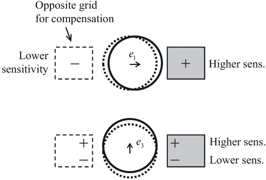
Grid sensitivity to longitudinal and transversal eccentricity components.
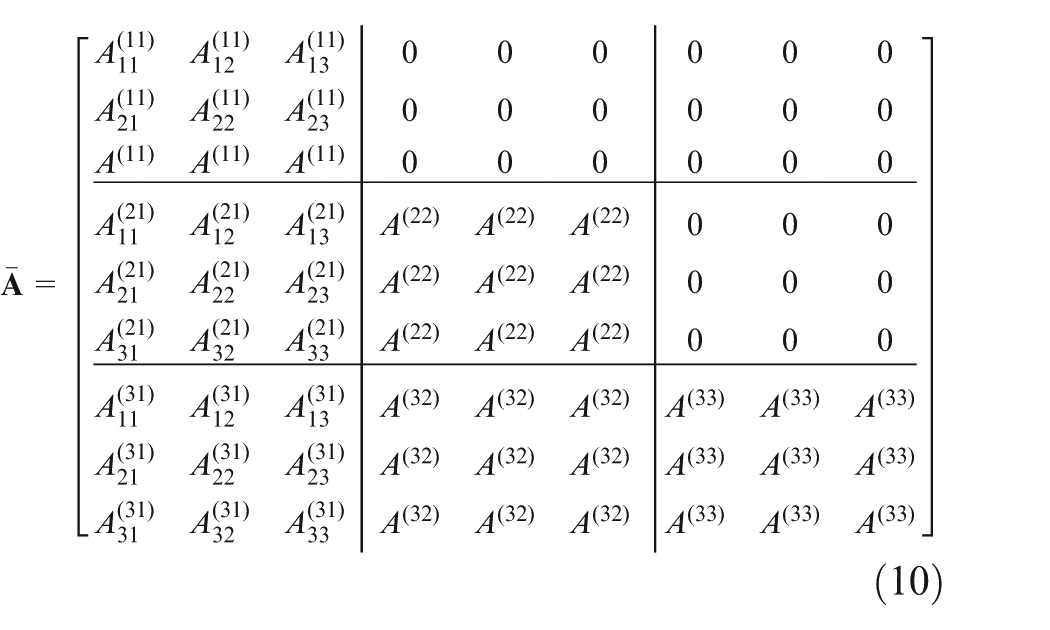
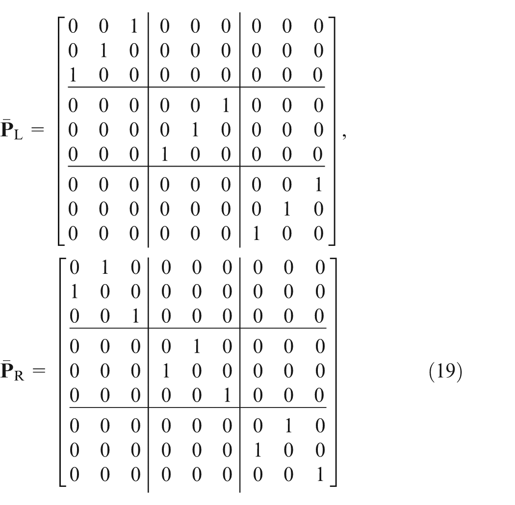
For common hole-drilling, without any compensating extra grid, the problem reformulated according to equation (9) seems to require many terms. In reality, the symmetry properties reduce the number of free parameters of the matrix
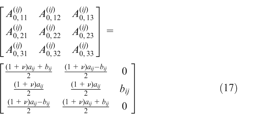
Equation (17) only shows a single block of the matrix

in which
Finite element modelling
A parametric finite element (FE) model was implemented to determine the coefficients of the matrices introduced above. The axial-symmetric geometry enabled structural plane harmonic elements (ANSYS Plane25) to be used. A full three-dimensional model, as proposed by Aoh and Wei
44
and Xiao and Rong,
45
was avoided in order to produce a very high spatial resolution in the region of interest with multiple nested refinements (Figure 3). The mesh division at the hole region was as small as one-hundredth of the radius, which was assumed equal to
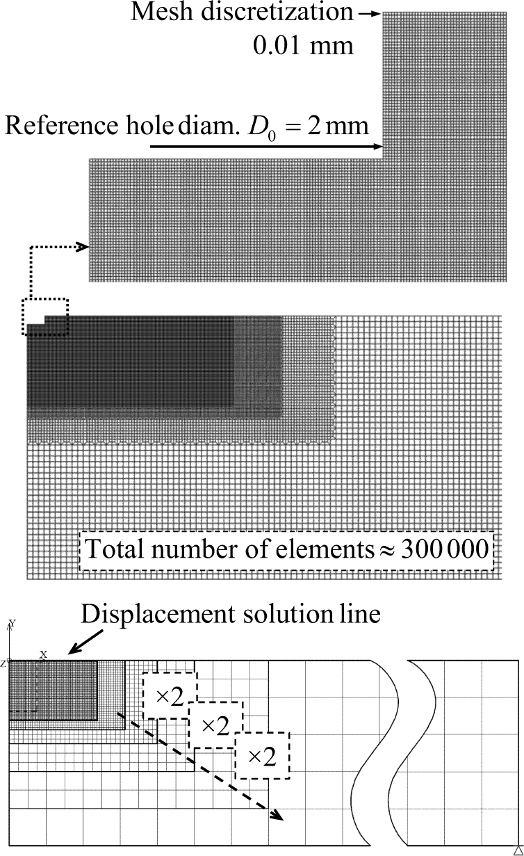
Plane FE model with axial-symmetric harmonic elements and multiple nested refinements.
Two types of load were imposed on the axial-symmetric harmonic model: equibiaxial and pure shear. As reported in Figure 4, the equibiaxial was obtained with the harmonic order zero, while the pure shear was obtained with the harmonic order 2, which is the tensorial dependence. To obtain the first load type, the removal of material with residual stress embedded was simulated as the application of pressure on the free cylindrical surface of the hole. Then, the pure shear was obtained as pressure (symmetric with respect to
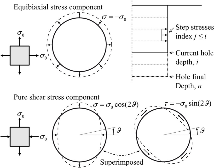
Simulation of material removal for the equibiaxial and the pure shear stress load types.
According to equations (7) and (9), the calibration coefficients can be interpreted as the relaxed strains induced by unitary residual stresses. The strains measured by the grids were numerically simulated from the FE analysis displacements by considering the angular
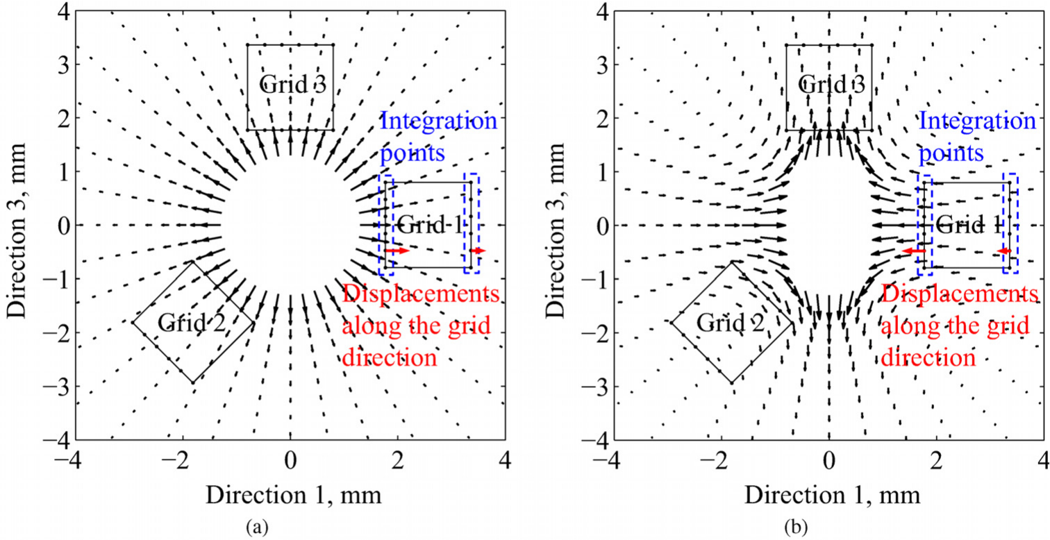
Type A rosette, displacement fields for (a) the equibiaxial and (b) the pure shear load components.
Calibration coefficient matrices
Standard calibration coefficients with no eccentricity
Although already available on the ASTM E837 standard,
31
the calibration matrices
Percentage differences obtained with respect to the ASTM type A,
The role of the Poisson’s ratio
Percentage differences for the Poisson’s ratio,
First-order correction for eccentricity
All the coefficients in matrix
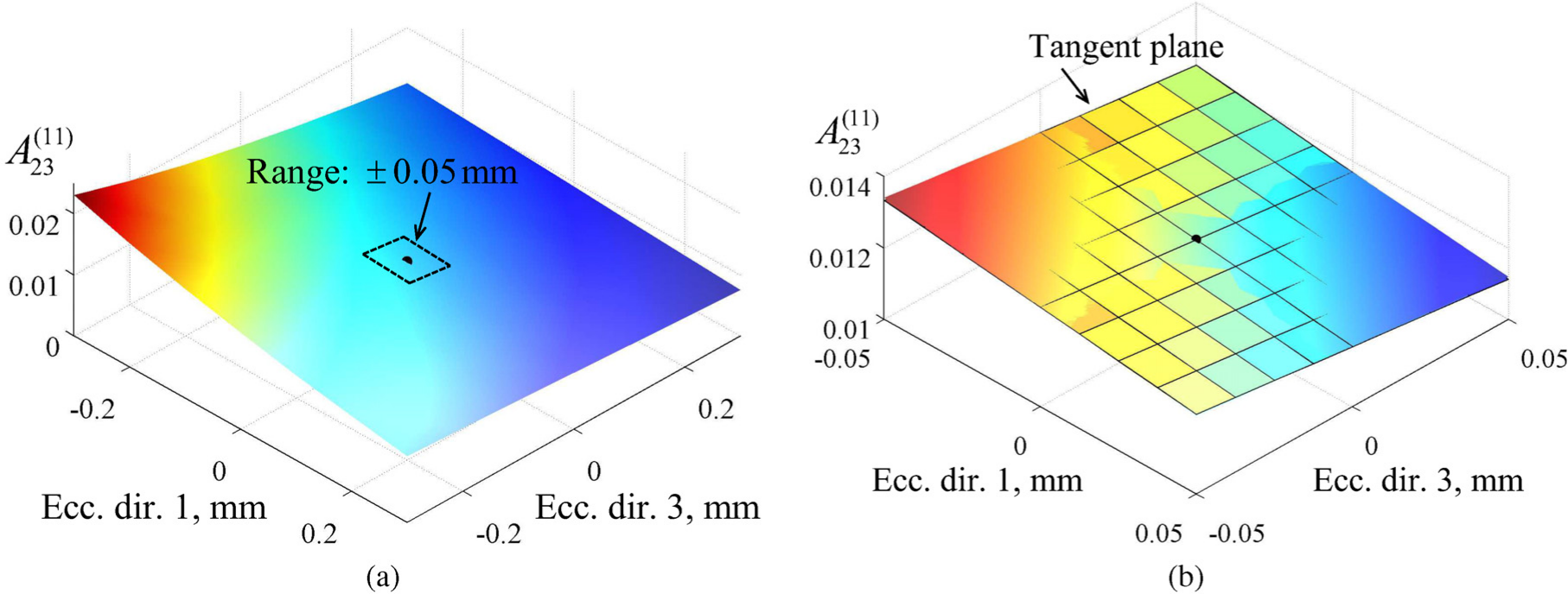
Eccentricity dependence of a single coefficient of matrix
The Poisson’s ratio dependence of matrix
Validation analysis
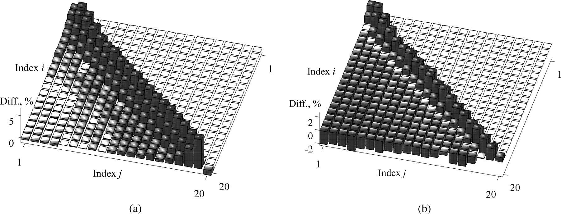
Numerical tests are proposed in this section to validate the introduced eccentricity correction procedure. Using the algorithm developed by Beghini et al.41,42 based on influence functions, any residual stress distribution can be simulated solving the direct problem and the relaxed strains along the depth predicted. The residual stress distribution, which is assumed as being uniform for the sake of simplicity, was initially back-calculated with the integral method according to the standard, applying the usual
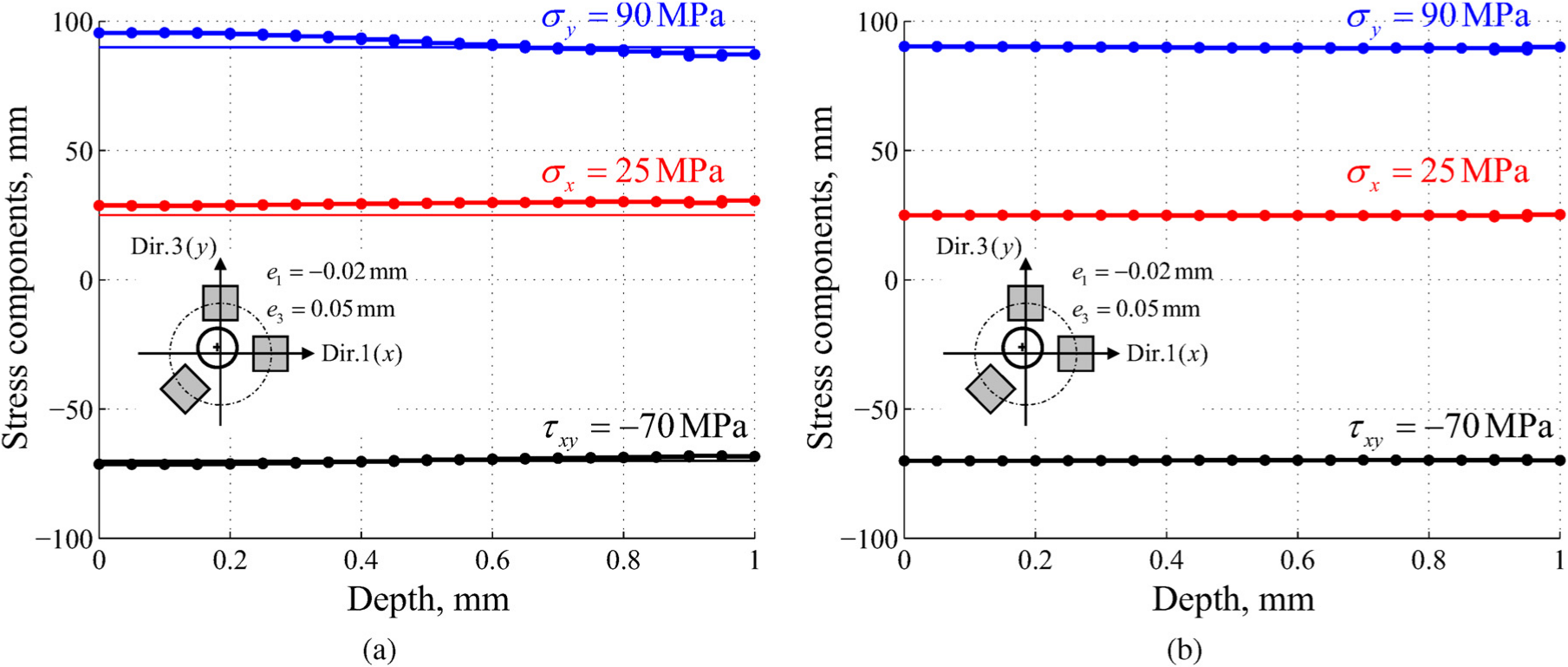
Validation example with type A rosette: (a) error caused by the eccentricity and (b) almost perfect result with the first-order correction.
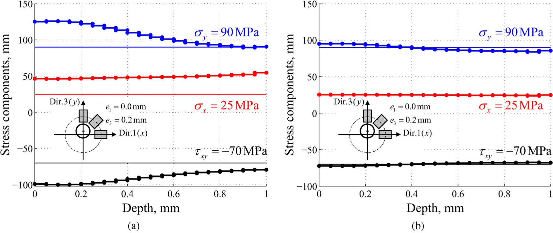
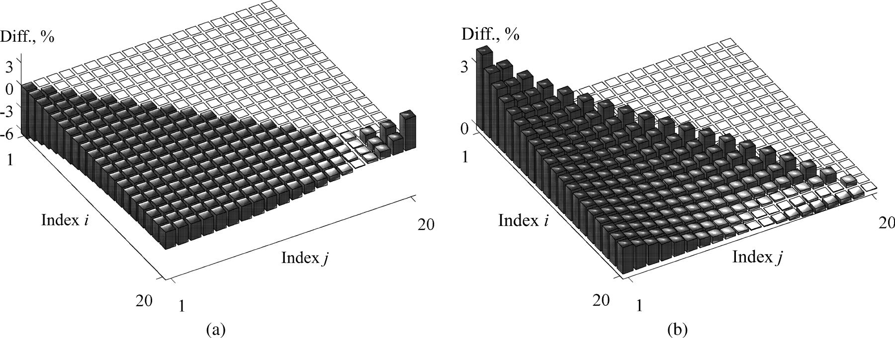
Validation example with type B rosette: (a) error caused by a large eccentricity and (b) accurate result with the first-order correction.
A wider analysis was then performed to test the effect of eccentricity and verify the correction introduced by the procedure, covering all the combinations of eccentricity values and stresses. Six levels of eccentricity were considered:
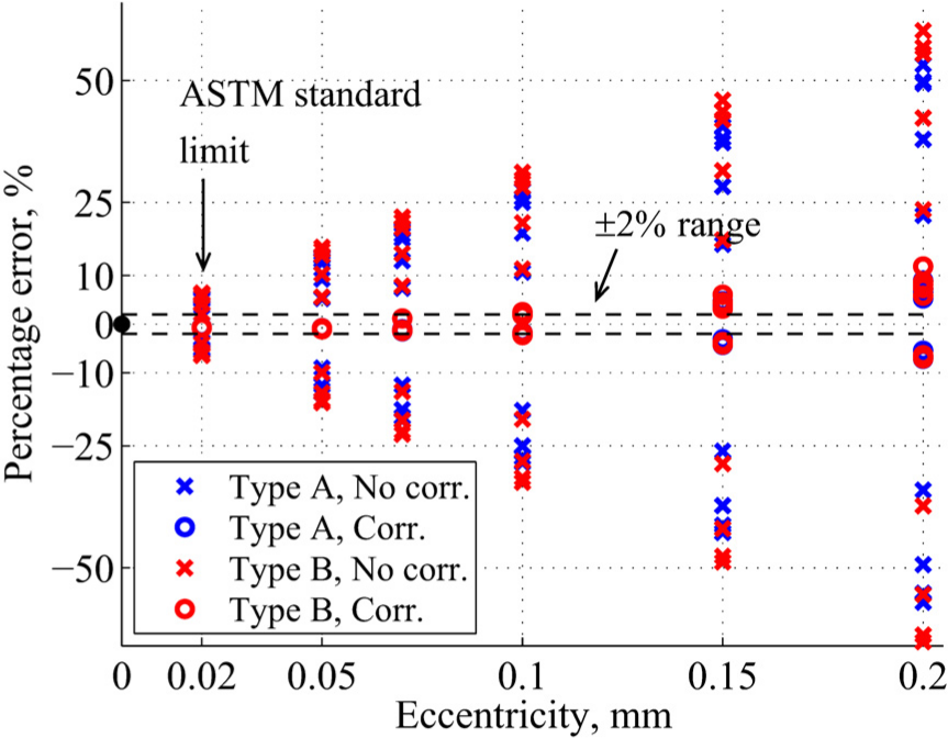
Maximum percentage errors for several combinations of eccentricity positions and stresses, and corrections obtained with the proposed procedure.
Conclusion
We have described a generalization of the hole-drilling integral method, which includes a correction for the eccentricity of the hole with respect to the strain-gage rosette. The eccentricity impairs the axial symmetry of the problem; thus, the decoupling of the stress components in an equibiaxial plus two shear stresses is no longer allowed. Consequently, a single matrix is needed to linearly relate the relaxed strains to the residual stress components. After having grouped the strains and the stresses in vectors along the depth, this matrix is a lower triangular 3 × 3 block, and each of its coefficients can be expressed as a power series of the eccentricity components. The two linear terms alone already proved to be a very accurate model for reproducing the eccentricity effect. The matrix was then expressed as the zero eccentricity term plus a linear correction of the two eccentricity components by introducing the derivative matrices. In addition, the
A very refined plane and axial-symmetric harmonic FE model was implemented and the calibration coefficients were calculated. Initially, a revision of the ASTM standard was proposed, according to the combined stresses and strains. The derivative matrices were then calculated and provided for both type A and type B strain-gage rosettes. Finally, an extensive numerical analysis was proposed both to validate the procedure and to show the accuracy of the correction. When the eccentricity is in the order of the small allowed limit prescribed by the standard, the reconstruction of the stress components with the eccentricity correction is very accurate. However, if the eccentricity is small, its measure uncertainty can be of the same entity of the eccentricity itself; thus, the present correction is not recommended. On the other hand, quite accurate results were still obtained with larger eccentricities, approximately up to 10 times the standard limit, since the linear first order is a fine model even for relatively high eccentricity values. In conclusion, the proposed procedure can significantly increase the eccentricity allowed and, even when the hole is produced with a large offset for any experimental reason, the measure can still be useful instead of being discarded or repeated.
Footnotes
Appendix 1
Declaration of conflicting interests
The author(s) declared no potential conflicts of interest with respect to the research, authorship and/or publication of this article.
Funding
The author(s) disclosed receipt of the following financial support for the research, authorship, and/or publication of this article: This work was supported by the University of Pisa under the ‘PRA – Progetti di Ricerca di Ateneo’ (Institutional Research Grants) – Project No. PRA_2016_36.
References
Supplementary Material
Please find the following supplemental material available below.
For Open Access articles published under a Creative Commons License, all supplemental material carries the same license as the article it is associated with.
For non-Open Access articles published, all supplemental material carries a non-exclusive license, and permission requests for re-use of supplemental material or any part of supplemental material shall be sent directly to the copyright owner as specified in the copyright notice associated with the article.