
Abstract
In engineering education, the topic of torsion is taught in both calculus and mechanics of materials, but using different definitions. Apparently, a clear connection between these two concepts is not currently found in the literature. In this paper, for the case of a homogeneous linear-elastic cylindrical shaft subjected to external torques, mathematical expressions are derived for relating torsional stress, strain and angle of twist to the torsion of a curve as taught in calculus. A physical connection is also presented, in that the curve torsion resulting from the deformation of a longitudinal line close to the shaft axis is shown to be approximately equal to the mechanical twist per length in the shaft. Although some researchers have hinted at this connection, to our knowledge the full precise connection has not been previously established.
Introduction
Within the undergraduate education of mechanical engineering students, the term “torsion” is encountered within more than one context. In mechanics of materials, torsion refers to the analysis of stress, strain, and twist in shafts subjected to externally applied torques. In calculus, torsion refers to a geometric property of a space curve in terms of the tangent, normal and binormal vectors along the curve. Although one would expect there to be a connection between the definitions of torsion within mechanics of materials and calculus, it appears that this connection is not provided explicitly in the literature or textbooks in either discipline. Moreover, it is not apparent whether a simple but meaningful interpretation of any such connection exists.
In this paper, we investigate this problem by reviewing the definition of torsion in both calculus and mechanics of materials, establishing the mathematical connection between the two sets of definitions, and developing a simple physical interpretation which may be used to provide insight and understanding in the classroom. Throughout the discourse, we use language and descriptions that would be appropriate for teaching undergraduate students in introductory courses.
Background
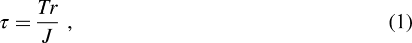
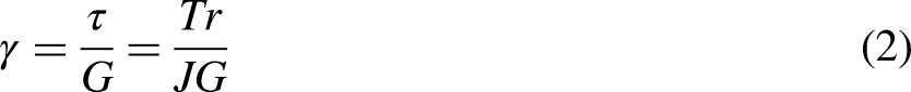
In mechanics of materials, torsion refers to a mechanical, physical process, where a bar is twisted due to external torques, and we are interested in the shearing stress, shearing strain and relative angle of twist. See Figure 1(a). For the classical mechanics of materials problem of a shaft of radius R and length ΔL with homogeneous linear-elastic isotropic material behavior and for a constant (solid or hollow) circular cross section, the classical solution is well known. At a distance r from the shaft center, the torsional shearing stress is

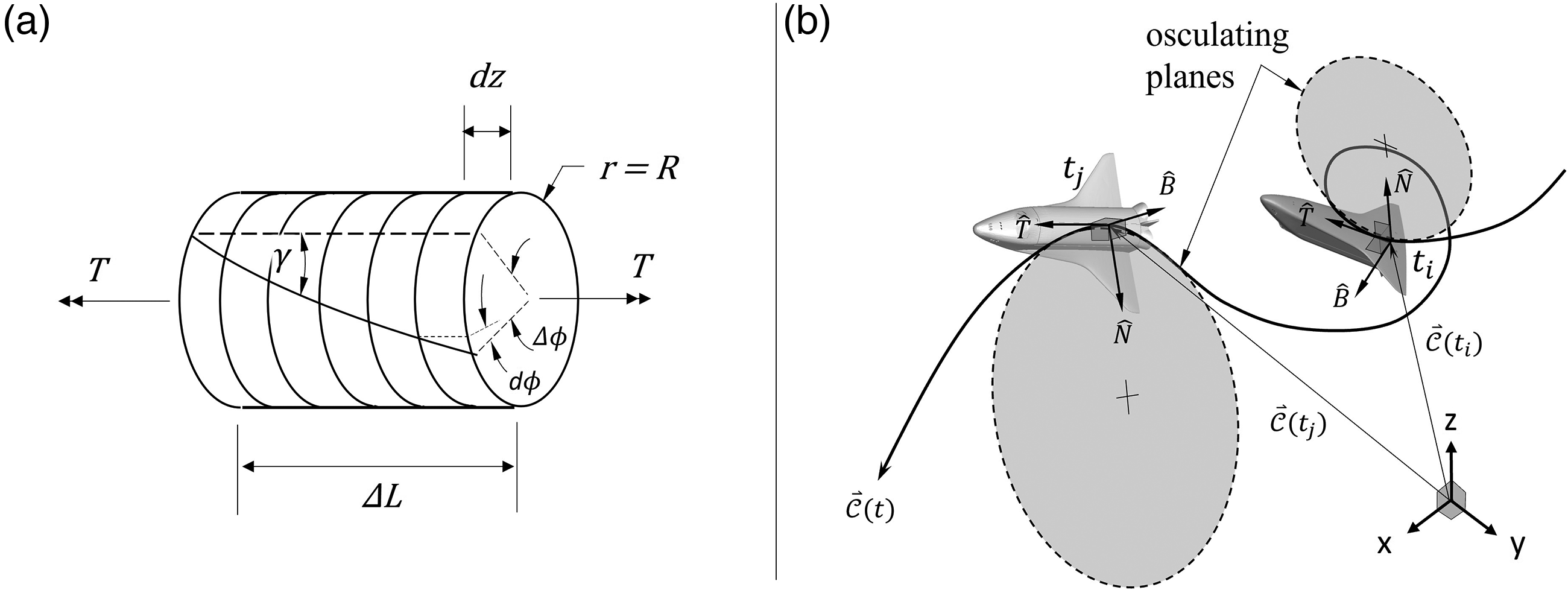
Comparison between torsion in mechanics of materials (a) and vector calculus (b). Common applications of torsion in mechanics of materials include the twisting of a drive shaft (deformable body distortion), whereas, in vector calculus, curve torsion could describe the roll of an airplane (rigid body rotation) throughout its flight trajectory.
In calculus, the engineering student encounters torsion in a different context. Here, the properties of a space curve are introduced, and key to this is the definition of three orthonormal vectors, the tangent,
For any curve,
Clearly, in the mechanics of materials and calculus definitions of torsion, there is a similarity in that there is a turning effect when traversing along a shaft in mechanics of materials, or along a space curve in calculus. With that said, even though there is a sense of “turning” in each of them, to a student it is not obvious how the two definitions of torsion are related; rather, it is an instinctive feeling. In the next section, we explore the literature in mechanics of materials and calculus, to ascertain whether anyone has stated very clearly what this connection is (if there is one).
Torsion in the literature
To the best of the authors’ knowledge, no explicit relationship between curve torsion and torsional stress has been made; however, an assumption concerning the two subjects is sometimes adopted immediately as true, whereas in fact it does not always hold (as shown in this paper). The relations presented in this paper (or their equivalents) were not found after reviewing different texts, including historical records,3–7 scientific works by pioneer elasticians,8–13 contemporary textbooks1,2,14–41 (including calculus texts1,14,19 and mechanics texts22,23,25,30–36 commonly used in Canadian engineering education, as per consultation with several universities) and research articles (in calculus42–46 and mechanics of materials47–63). Among these materials, spanning throughout several centuries, continents and languages, great resources for the fascinating historical development of the solution to the torsion problem include work by Benecke et al., 48 Casey et al., 5 Higgins 6 and Todhunter. 3 Whereas, in the past, research efforts were spent in developing the fundamental theories commonly used today to study bodies undergoing torsional deformation, which greatly consisted of finding analytical solutions to differential equations describing such problems,3,8–13 modern research looks very different. Current studies seem split among arbitrary space curves’ curvature and torsion estimators,42,43,45 kinematic descriptions of torsional deformation separate from mechanical loading and material behavior,46,50,53,61 analytical solutions48,51,63 and numerical (finite element) approximations52,54–58,62 to solid mechanics problems involving twisting (static or dynamic), and industrial applications concerning mechanical elements (e.g., gear shafts, helical springs, and especially braided rope46,49,50,53,56,62).
Across the aforementioned applications, only a few documents3,8,48,49 hint at a relation between the torsion definitions in differential geometry and mechanics of materials, by incorporating an assumption involving twist angle and curve torsion for a material fiber of a cylinder undergoing twisting, but without being explicit about this. In these documents, the equivalence between curve torsion of a deformed fiber (which was originally straight and longitudinal prior to deforming into a helix) and the twist per length of the cylinder which is subjected to torsional deformation is adopted immediately as true. However, this equivalence is only a special case (for cylinders or wires of small diameter relative to their length), as shown later in this paper. In fact, the fundamental idea behind the general case that formerly straight lines undergoing twisting become helices, which was first demonstrated by Wantzel in the 1800's,4,8 is only discussed in relatively few papers.3,4,8 Only one paper, 11 by Saint-Venant himself, recognizes the importance of distinguishing curve torsion from mechanical torsion, indicating that they are indeed different entities. Saint-Venant proposed that a new name should be given to curve torsion to avoid confusion.
In this paper, we provide a mathematical analysis and physical interpretation to clarify the issues. In particular, we consider the specific problem where a circular cylinder of constant cross section is subjected to torques of equal magnitude and opposite directions at its two ends. This cylinder is made of a material which is modeled as homogeneous, isotropic and linear-elastic. It is assumed that the cylinder did not have a preload or residual stresses prior to loading, to facilitate development towards the fundamental relationships to follow. Under these conditions, the torsional stress, shearing strain, twist angle and curve torsion can be determined using methods taught in introductory mechanics of materials and introductory multivariable calculus courses at the university level.
Prelude to the analysis
There are some distinct differences between how torsion is taught in calculus and how torsion is taught in mechanics of materials. In particular, within calculus, torsion is a mathematical property of a space curve, where that property does not rely upon how that space curve was physically created. In contrast, the curves of interest due to mechanical torsion are typically the result of deformation due to loading which causes straight longitudinal lines to take a curved shape according to the kinematics of deformation. Although torsion of a space curve according to calculus could be used to describe a curve that existed prior to loading (such as a curved line “drawn” on the surface of an unloaded shaft), to make the connection between calculus and mechanics of materials we will always be considering those curved lines created by deformation. We will also need to include shearing stress (a tensor component due to mechanical loading) in the formulation. Although calculus focuses only on geometry of a curve, in mechanics of materials shearing stress is an essential quantity.
In this paper, we work towards relating space curve equations to mechanical torsion formulas for an axisymmetric shaft subjected to torsional loading. Since the classical formula for shearing stress is well known, the relationship is developed by exploring the connection between mathematical torsion of a curve and torsional shearing stress.
When a shaft is twisted, it appears that longitudinal lines drawn on the surface become curves, with their curve torsion depending on the extent of the twisting. (The changes in longitudinal lines due to torsion can be demonstrated in the classroom using a foam cylinder that can be easily twisted, with a grid of longitudinal and circumferential lines drawn on the surface. 64 ) Moreover, as per the mechanics of materials equations, shearing stress can be computed at any distance r from the shaft axis, while, from calculus, the curve torsion can be calculated for a curve of any size and at any location (e.g., placed at a distance r from a polar origin). In our analysis, we connect these two theories using this r-coordinate.
In particular, the approach taken in this paper uses the following steps:
Determine the curve family which describes exactly the mechanics of deformation in axisymmetric members under torsion. Manipulate the curve torsion expression (i.e., curve torsion Manipulate the mechanics of materials torsion equation (shearing stress τ as a function of location r), so that the r-coordinate is expressed as a function of τ. Set the two rearranged expressions for the r-coordinate equal to each other, and determine the connection between curve torsion and shearing stress. Finally, use the mechanics of materials relations between stress, strain, and angle of twist to determine a relationship between curve torsion and angle of twist.
As it will be shown, this leads to mathematical relations and physical interpretations that clearly establish the desired connections, and which are potentially useful for teaching undergraduate students.
Mathematical formulation
Let z be the longitudinal axis passing through the geometric center of a cylindrical shaft (or segment) of length ΔL, as shown in Figure 2. As the shaft undergoes twisting, visualize what happens to a set of material points initially forming a straight line parallel to this z-axis and offset by an arbitrary distance r (Figure 2).
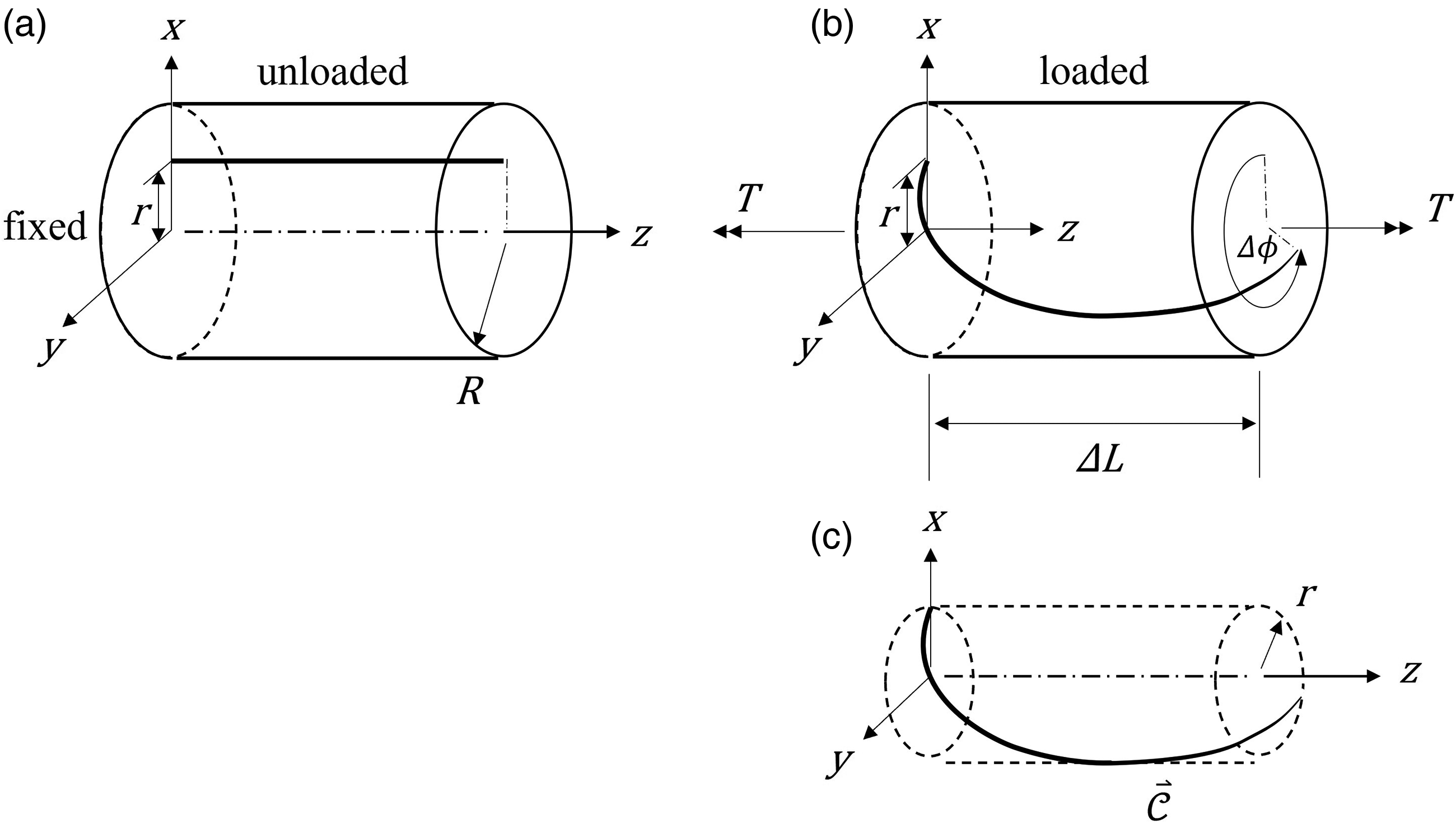
Undeformed (a) and deformed (b) configurations of a shaft under torsional loading, showing twisted curve (c) which was originally a straight line.
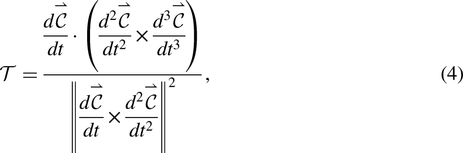
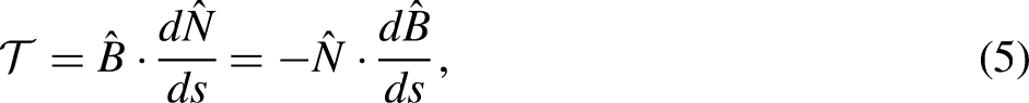
To find a relation between the resulting curve torsion,

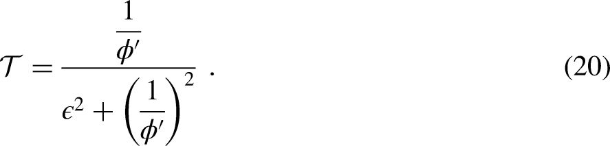
For our specific helix parametrization, the curve torsion expression (equation (4)) becomes
1

It is important to note that equations (6) and (7) are valid expressions of a helix only for
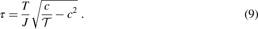
Rearranging equation (7), we can express the curve offset (i.e., the initial location of the straight line) in terms of its curve torsion:
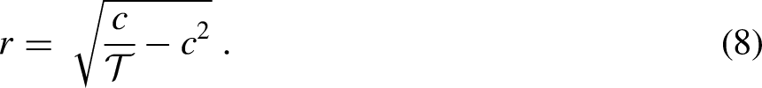
Thus, substituting equation (8) into equation (1), we obtain a relation between curve torsion and shearing stress:
Perspective and axial view of a twisted curve (helix) which was originally a straight line.
Referring to Figure 3, for the curve at the shaft's right end,


Referring again to Figure 3,


Physical interpretation
To develop a physical interpretation connecting torsion in calculus and torsion in mechanics of materials, it is reasonable to expect that this connection would come through relating curve torsion and angle of twist, because both of these are geometric (i.e., kinematic) quantities.
We therefore start again by considering how a line that was originally straight longitudinally along the shaft changes its shape due to torsional loading (Figure 4(a)). Once more, let us emphasize that in this mechanical process, for a shaft of constant circular cross section, the shaft is regarded as being composed of an infinite number of (disk) elements, each turning relative to each other at a constant twist per length. However, for an arbitrary longitudinal line, from calculus, we picture how the Frenet-Serret frame changes angle when moving along the deformed curve, as per the curve torsion (Figure 4(b)). Whereas curve torsion and the corresponding rate of turning of the osculating plane are constant throughout the helical deformed curve, equation (17) shows that curve torsion is not synonymous with twist per length. These rates of turning are indeed different, as twist per length and curve torsion describe different aspects of the geometry of deformation. However, since the geometric response is the same (regardless of its descriptions), their physical meaning must be related. To actually “see” the connection, let us carefully examine what the final relations tell us about the extreme cases of r, in particular when
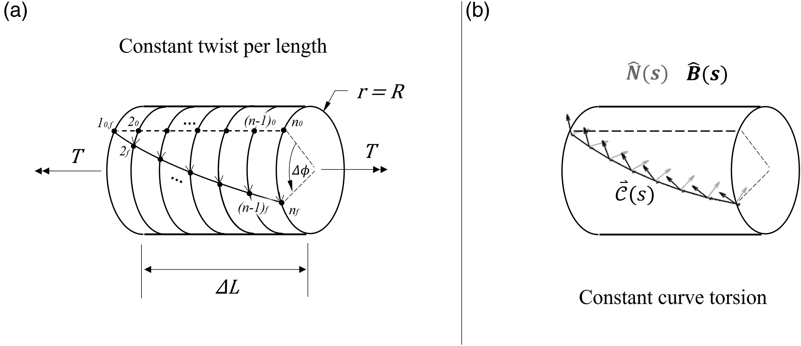
Torsion effects in (a) mechanics of materials, showing n material points [1, 2, …, n-1, n] before and after loading (with 0 and f subscripts denoting initial and final states respectively), and (b) vector calculus, showing normal and binormal coordinates along the deformed curve.
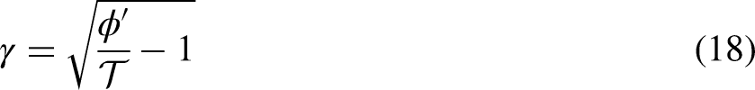
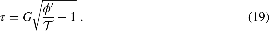
From mechanics of materials theory (equations (1) and (3)), the torsional shearing stress is zero at r = 0 and maximum at r = R (Figure 5(a)), while twist per length is constant. However, regarding the corresponding curve torsion, equation (19) shows that, for
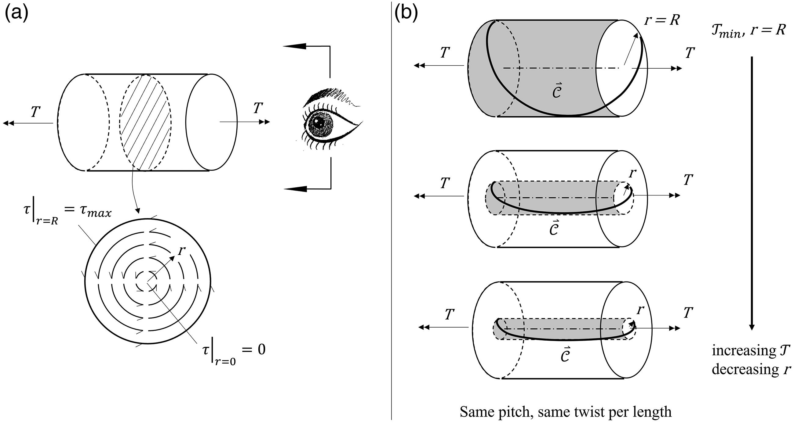
Torsional shear stress (a) and curve torsion (b) distributions; equipotential surfaces (where both torsional stress and curve torsion are constant) grayed out.
As such, away from the shaft's axis, the mechanics of materials description of torsion (
To reconcile the apparent disconnect between the increasing curve torsion for decreasing r and the curve becoming a straight line (with indeterminate curve torsion) exactly at r = 0, consider again the mathematical relationship between twist per length and curve torsion, equation (17). Let us look at what happens when r is arbitrarily small (but not zero).
Let

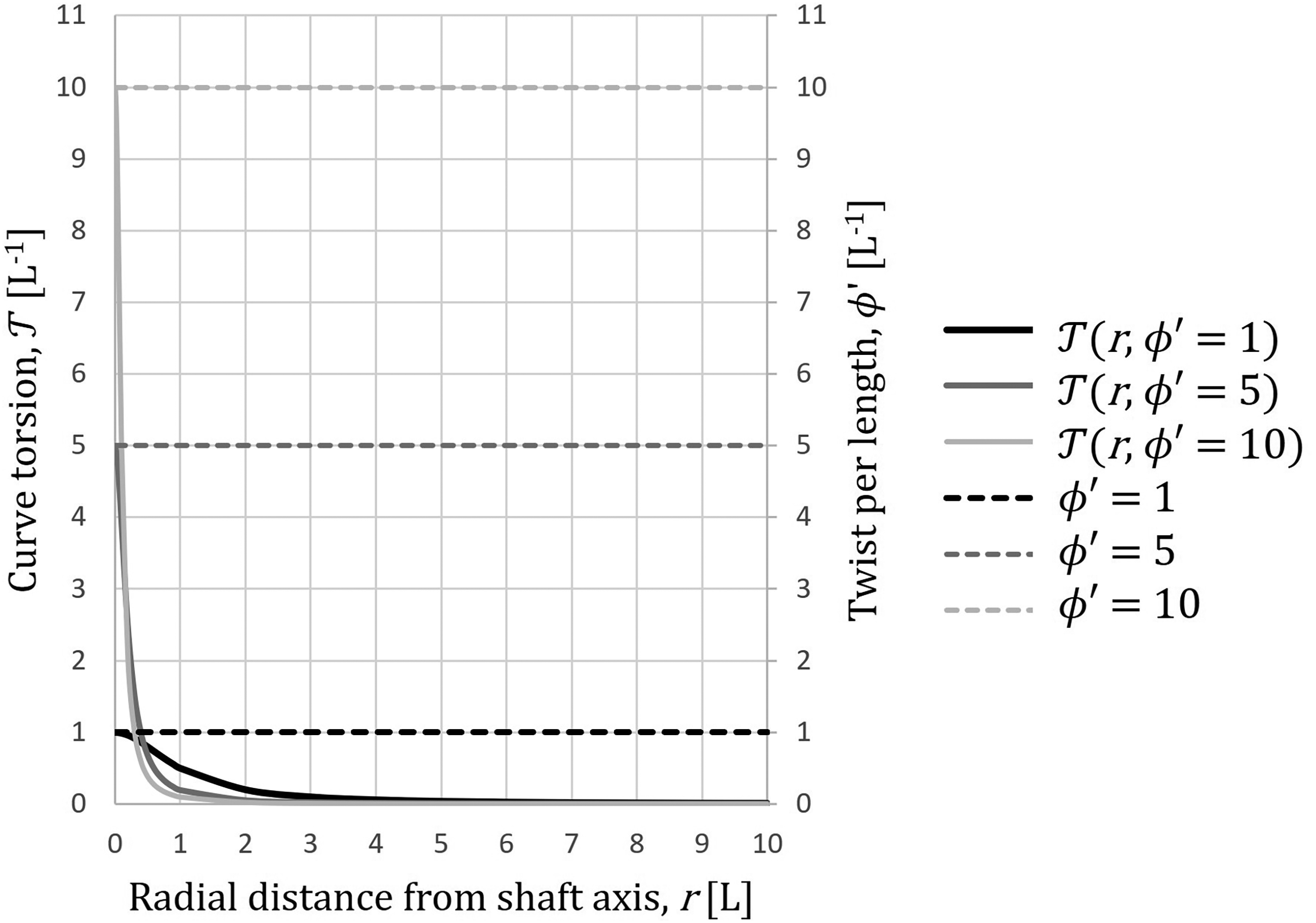
Curve torsion and twist per length as functions of radial distance from the shaft axis for selected values of twist per length. The notation [L] is used to refer to generalized length units.
Unfortunately, this physical interpretation must remain an approximation and cannot be applied at r = 0, where the helices of deformation degenerate into a straight line. By definition, straight lines have zero curvature, but do not have curve torsion; i.e., curve torsion cannot be defined for straight lines as the binormal vector of the osculating plane (of infinite radius) could point in all directions about the line. Perhaps this is one of the reasons why this connection has been elusive.
It was quite surprising for us that curve torsion has an upper bound of
It is important to note that any helix close to the shaft axis can approximately describe the twisting deformation of the entire shaft. Furthermore, when the helix envelope is reduced to describe the shaft near but not including its axis, this helix resembles a straight line. To complete the puzzle, at r = 0, the shaft is described only by a straight line along its axis without curvature or curve torsion. This implies that the entire mechanical deformation field of a twisting shaft can be decomposed into helices that span throughout the shaft domain, and all of these are centered on a straight line through the shaft axis, which anchors the geometry.
In summary, as
Deeper insight into the link between curve torsion & twist per length
How could this difference between curve torsion and angle of twist per length have been left unaddressed in the history of torsion up until now? To reconcile this, let us consider again equation (17) and Figure 6. However, this time, let us examine wider ranges of loading (in the form of twist per length) and shaft radii. As Figure 7(a) shows, a linear scale prevents us from appreciating the behavior of the curve torsion over these large scales of size and loading. While magnifying (uniform scaling) might seem a viable option, we would lose sight of the rest of the domain, along with the big picture, in this case.
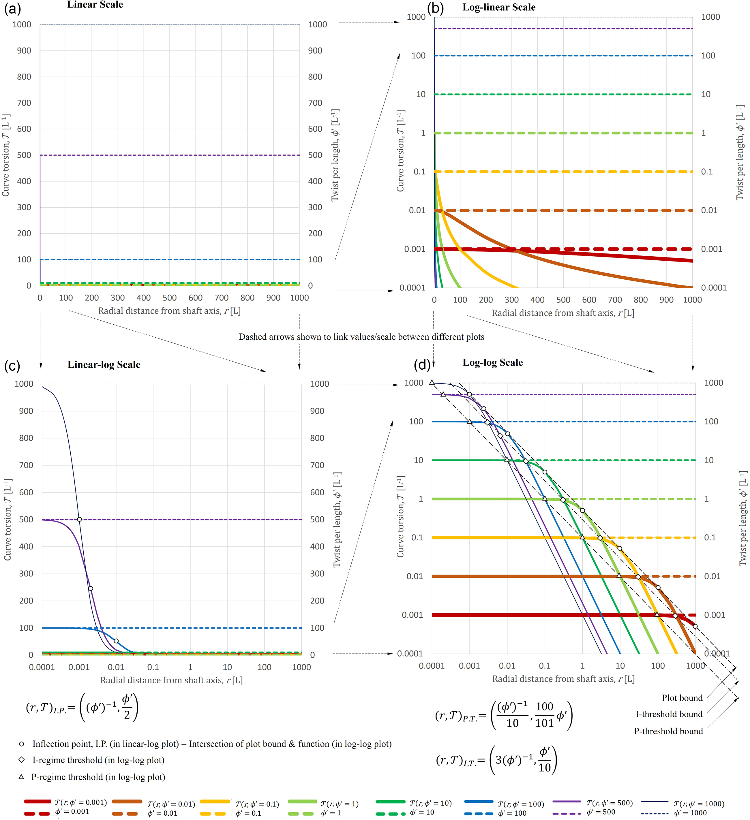
Features of the curve torsion function of radial distance under (a) linear, (b) log-linear, (c) linear-log and (d) log-log scales. Due to the nature of these functions, it is difficult to see them in a linear plot; hence, log-transformations (base 10) are used to facilitate understanding this family of functions. Log-linear provides the best visualization for twist per length as the limiting value of curve torsion, linear-log best shows the sigmoid-like behavior of the curve torsion function, and log-log presents a unique shape with three regions: Plateau (P), transitional (T) and inclined (I).
It may be more revealing to examine these plots using logarithmic transformations (nonlinear scaling, base 10 in this case), as they allow us to virtually zoom into particular regions, while still considering the entire scale of size and loading. Log-linear scales (Figure 7(b)) allow us to clearly see how fast the curve torsion approaches its corresponding twist per length. However, this plot also suggests there might be points of inflection in these functions. Evidently, linear-log scaling (Figure 7(c)) shows there is a transition in curve torsion from a horizontal asymptote of
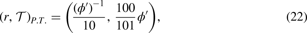
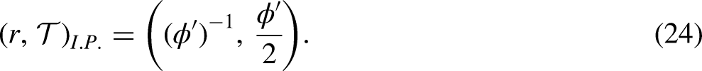
Log-log scales clearly show three characteristic regimes in all curve torsion functions. First, there appears to be a flat plateau for very small shaft radii and up until a certain threshold, which increases with decreasing twist per length. On the other hand, for very large shaft radii, it seems that the logarithm of curve torsion decreases proportionally with respect to the logarithm of shaft radius along a downward incline. Once again, this inclined region starts from a specific threshold, which decreases with increasing twist per length. Finally, all functions exhibit a similar transition connecting the plateau and inclined regions. In fact, all these functions in the log-log plot are the same, by the fundamental theorem of curves, just differing by placement (due to twist per length). What is most useful about this visualization is perhaps that it shows over which domains the assumption of curve torsion being approximately equal to twist per length is true (i.e., throughout the plateau). Moreover, as we leave the plateau, curve torsion deviates significantly from this value for large radii and/or large twists per length (i.e., over the transitional and inclined regions). It should be clarified that it only appears there is a “flat” plateau and “linear” inclined region; equation (17) remains nonlinear throughout all its regimes, which is evident from its non-zero curvature at all points in the log-log plot.
The results in Figure 7(c) give rise to an expression for the inflection point (I.P.), and the results in Figure 7(d) give rise to expressions for the plateau and incline thresholds (P.T and I.T., respectively), for the plotted functions. Interestingly, these features are related to the physical characteristics of the problem. Although these expressions were developed from a geometric point of view, they can be derived analytically. Such expressions are as follows:

So, what is the relevance of the curve torsion regimes in regard to reconciling the connection between curve torsion and twist per length? To answer this question, we solved some classical linear-elastic torsion problems
33
using linear elasticity theory, i.e., equations (1) to (3), and the method presented in this paper, i.e., equations (17) to (19), while monitoring twist per length and curve torsion. It turns out that such examples fell well within the plateau regime, and that both methods agreed with each other. For the problems considered, curve torsion was indeed extremely close to twist per length (with the largest difference being
From equations (22), (23) and (24) and the linear-elastic examples considered, we determined that curve torsion regimes are related to mechanical deformation regimes; however, we can also determine how far away from the plateau region the twist per length still provides a good approximation of the curve torsion. This can be assessed for any particular application with specific allowable error margins, by quantifying the percent difference between curve torsion and twist per length (Figure 8). It can be further shown that this error remains less than 1% throughout the plateau regime (which is probably why it looks flat despite also being nonlinear), equals ∼1% at the plateau threshold, and exceeds 1% beyond this critical shaft radius. The fact that the percentage difference varies continuously with respect to radius demonstrates that curve torsion is indeed a nonlinear function throughout all its regimes. It should be noted, however, that in cases where the percent difference is large, the assumption of linear elasticity would typically become invalid.
(a) Regimes for the curve torsion of a material fiber undergoing twisting (plateau (P), transitional (T) and inclined (I)), and (b) corresponding percent difference between curve torsion and twist per length for the case of Φ′ = 1 [L−1].
In summary, saying that curve torsion is approximately equal to twist per length is probably a reasonable approximation for most linear elasticity problems (e.g., as taught in undergraduate mechanical engineering courses). Beyond linear elasticity (e.g., in graduate courses in finite elasticity), our method would need to be extended to make the distinction between curve torsion and twist per length. The nature of this extension likely depends on the specific type of nonlinearity involved, which may encompass geometric nonlinearity, material nonlinearity, plasticity, effects of residual stresses, inelastic buckling, elastic buckling, and post-buckling phenomena.
Concluding remarks
In conclusion, our equations are equivalent to the mechanics of materials formula for torsional stress, and the relationships between curve torsion and the mechanical torsion quantities are given by equations (17), (18), (19), and (21). Equally important is the physical interpretation of the connection between torsion in calculus and torsion in mechanics of materials. That is, close to the axis of the shaft, the twist per length is indeed close to the curve torsion (and vice versa). In other words, for the tight helix near the axis of the cylinder, the
Footnotes
Acknowledgements
The authors gratefully acknowledge the literature review contributions provided by Jonah Roussel, undergraduate student, Department of Chemical Engineering, University of Saskatchewan. The authors would also like to thank Esteban Jiménez, radiology and medical physicist, Le Commissariat à l'énergie atomique et aux énergies alternatives, Institut National des Sciences et Techniques Nucléaires, for helping translate the French documents.
Declaration of conflicting interests
The authors declared no potential conflicts of interest with respect to the research, authorship, and/or publication of this article.
Funding
The authors received no financial support for the research, authorship, and/or publication of this article.
Data availability statement
Data sharing not applicable to this article as no datasets were generated or analyzed during the current study.
Appendix 1. Solved example illustrating how twist per length is closely related to curve torsion in linear-elastic torsion problems
Consider the following example, Concept Application 3.2 from Beer et al. 33 This problem involves a hollow cylindrical steel shaft that is fixed at one end and unsupported at the other. The shaft has the following geometric parameters: 1.5 m length, 40 mm inner diameter, and 60 mm outer diameter. A torque is applied to the unsupported end to produce a relative angle of twist of 2° between the two ends.
As per its definition, constant twist per length is given by
Now, using equation (17), the curve torsion of any outermost extreme fiber is
Similarly, from equation (17), the curve torsion of any innermost fiber is
Notice that for this linear-elastic problem involving a hollow cylinder with an average slenderness ratio (length / average radius) of 60, there is close agreement between curve torsion and twist per length. Also, note that this agreement improves closer to the shaft axis.