
Abstract
The aim of this study was to develop and validate a comprehensive heat balance model for reheat furnaces to quantify energy distribution and identify opportunities for minimising heat loss in secondary steelmaking operations. While reheat furnaces account for approximately 70% of energy consumption in secondary steelmaking, limited quantitative analysis exists on the distribution of heat losses across different operational parameters. A heat balance model was developed based on an assigned control volume approach, incorporating radiation and convection equations to quantify heat distribution. The model was validated using operational data from Infrabuild' Laverton steel mill at discharge rates of 86 tph and 92 tph, with temperature measurements used to calibrate the heat transfer calculations. Results showed that flue gas losses represented the highest contribution to total heat loss at 25%, while surface losses accounted for 17% of total energy output. Heat loss beneath the hearth emerged as the dominant component of surface losses, with temperatures reaching up to 500°C. The validated model demonstrates that surface heat losses are more significant than previously quantified, suggesting that improvements in thermal insulation beneath the hearth could yield substantial energy savings. This study provides steel manufacturers with quantitative data to prioritise energy efficiency improvements in reheat furnace operations.
Introduction
The manufacturing of steel is a highly energy-intensive process. Furnaces are the main energy-consuming units in industrial processes. In 2023, the steel industry consumed 8% of the world' energy production, utilising approximately 35 EJ and contributing to about 7% of global CO2 emissions. 1 Coal currently meets about 75% of the energy demand of this sector. There has been growing interest in reducing energy consumption in the recent years. This is primarily because of the pressure from society and governments around the world on the importance of sustainability. 2 Research into alternative energy sources has contributed immensely to taking a step away from fossil fuels and renewables. 3 However, clean energy remains expensive, especially for largely energy-intensive processes such as ironmaking and steelmaking. Reheat furnaces are the largest energy consumer in secondary steelmaking, responsible for approximately 70% of the energy use in the rolling mill. 3 They are used to heat billets, blooms or slabs that arrive from casting to temperatures suitable for rolling, generally ranging from 1000 °C up to 1300 °C. 4 Therefore, it is necessary to map the heat distribution to best utilise energy. 4 Building on Stanford et al.'s 5 energy balance framework, this study developed and validated a comprehensive heat-balance model of the Laverton walking hearth furnace. Quantifying heat flows through its preheat, heating, and soaking zones demonstrated how targeted interventions (e.g. enhanced insulation and maintenance) can be evaluated to optimise overall thermal efficiency.
Classification of reheat furnaces
Several types of reheat furnaces have been developed, each has its advantages and disadvantages. Primarily, these can be categorised as continuous and batch furnaces. Batch-type furnaces, termed ‘in-and-out furnaces’, have one temperature setpoint but via three zones of control to maintain a uniform temperature throughout. They may be loaded manually, or by a manipulator or a robot. Loads are placed in the furnace; the furnace and its loads are brought up to temperature. Depending on the process, the furnace may be cooled before it is opened and the load removed, generally through a single charging and discharging door. 6
Continuous furnaces move the charged material, stock, or load while it is being heated. The material passes over a stationary hearth, or the hearth itself moves. If the hearth is stationary, the material is pushed over skids or rolls or is moved through the furnace by woven wire belts or mechanical pushers. A continuous furnace operates at a constant heat input rate except for delays, with burners rarely shut off. A constantly moving conveyor or hearth eliminates the need to cool and reheat the furnace (as with a batch furnace), thus saving energy. These can be further classified depending on the heating methods and heat recovery. Heat is generated for the process either by combustion of fuel or conversion of electrical energy to heat. Fuel-fired furnaces are the most widely used.6,7 However, electrical-based furnaces are used where they offer advantages that might not be measured in terms of fuel cost.
Walking hearth furnace
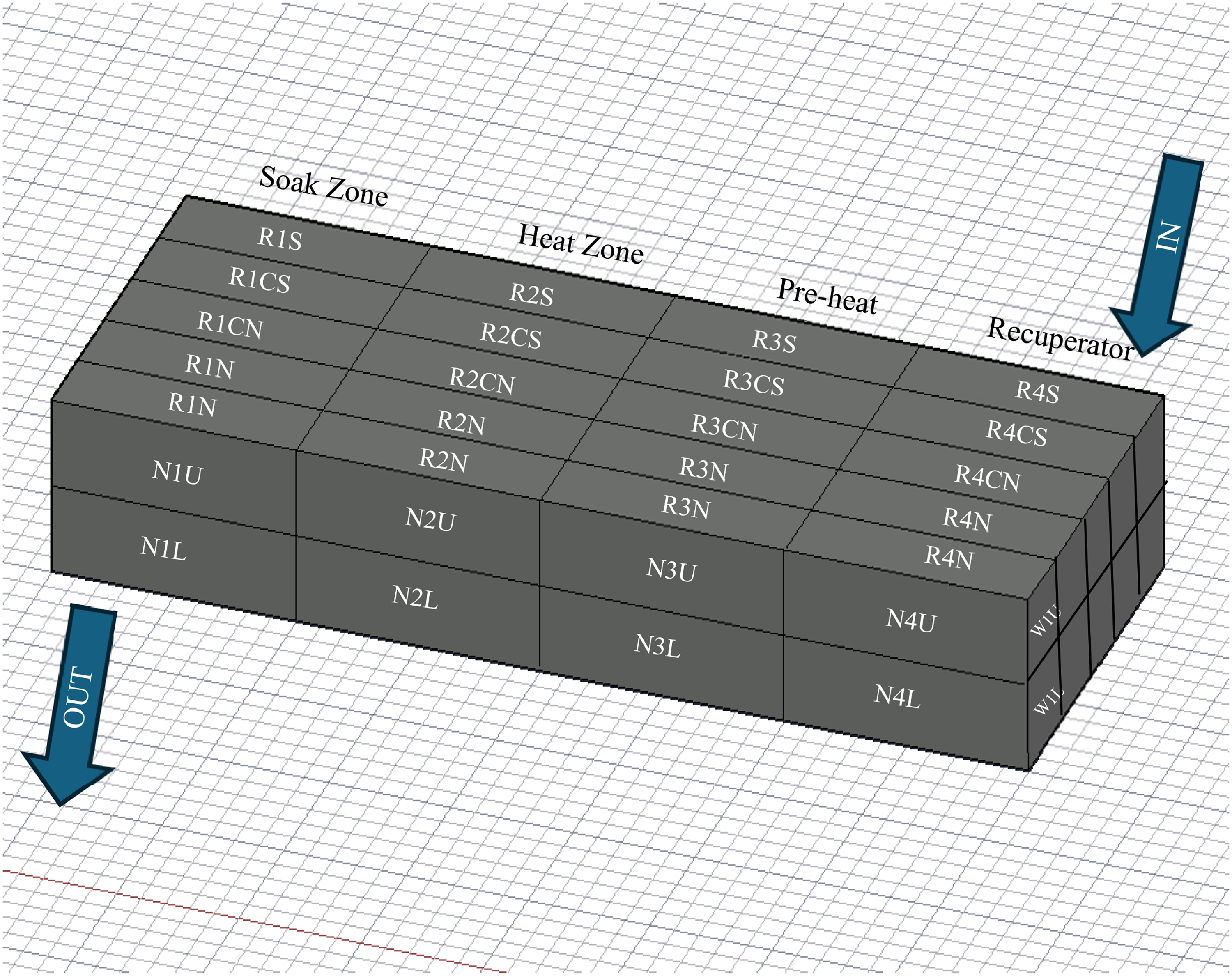
The reheat furnace studied in this research project is at Infrabuild' Laverton Steel Mill. Initially constructed in 1996, it is a walking hearth reheat furnace consisting of three main zones. Billets pass through a preheat, heating, and soaking zone before being discharged at approximately 1200 °C. The basic layout of the furnace is depicted in Figure 1.
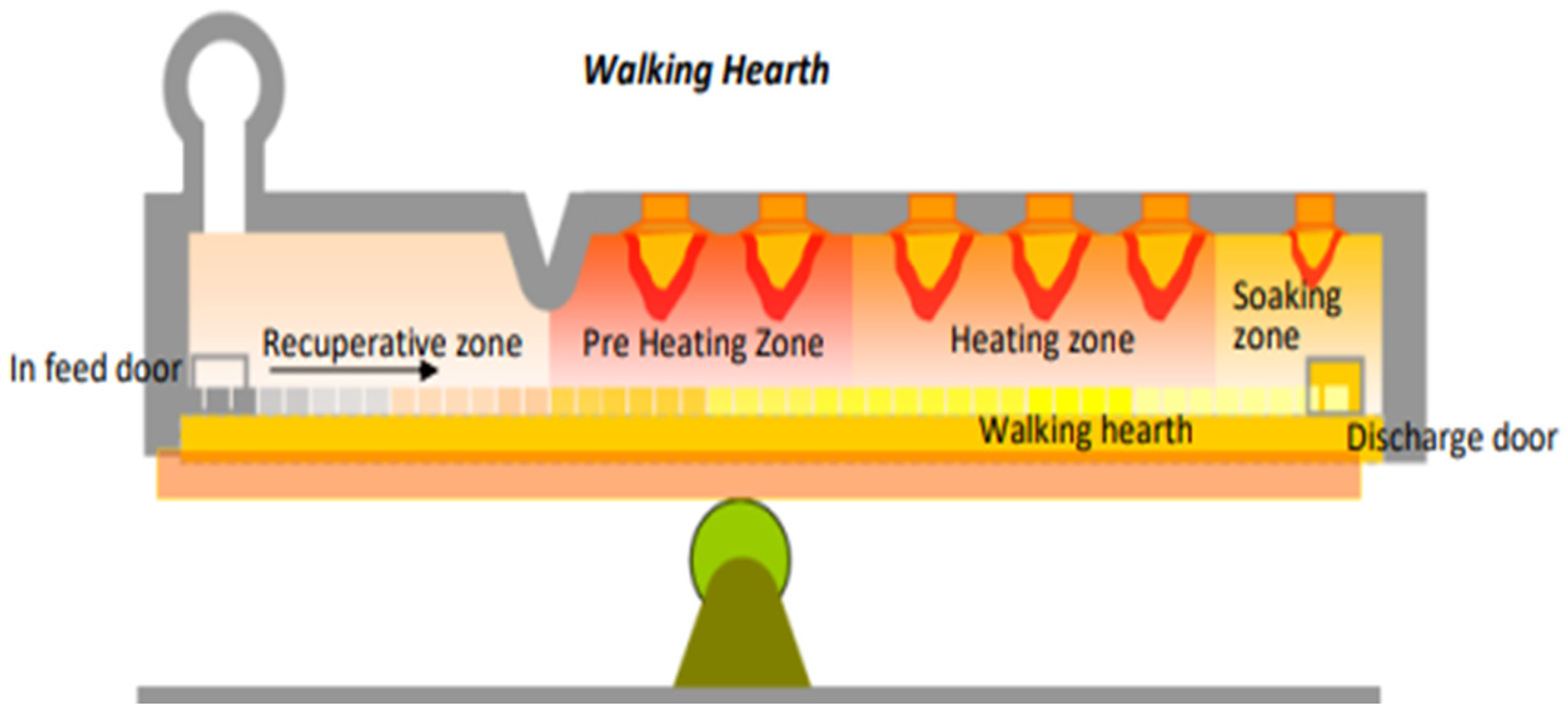
Zones of the walking hearth furnace.
The walking hearth furnace consists of steel billets that are rested on the fixed refractory piers. A walking hearth reheat furnace is a continuous process incorporating a series of longitudinal refractory hearths that allow the billets to be transported through the furnace zones using a hydraulic walk system. The billets within the furnace are moved through the furnace by raising the hearth vertically to gain first contact with the workpiece. Then, it continues to move upwards for a short distance, and then the hearth moves a pre-set distance and lowers the billets to its new position, as shown in the schematic in Figure 2. This process is continued till the billet reaches the discharge. 7
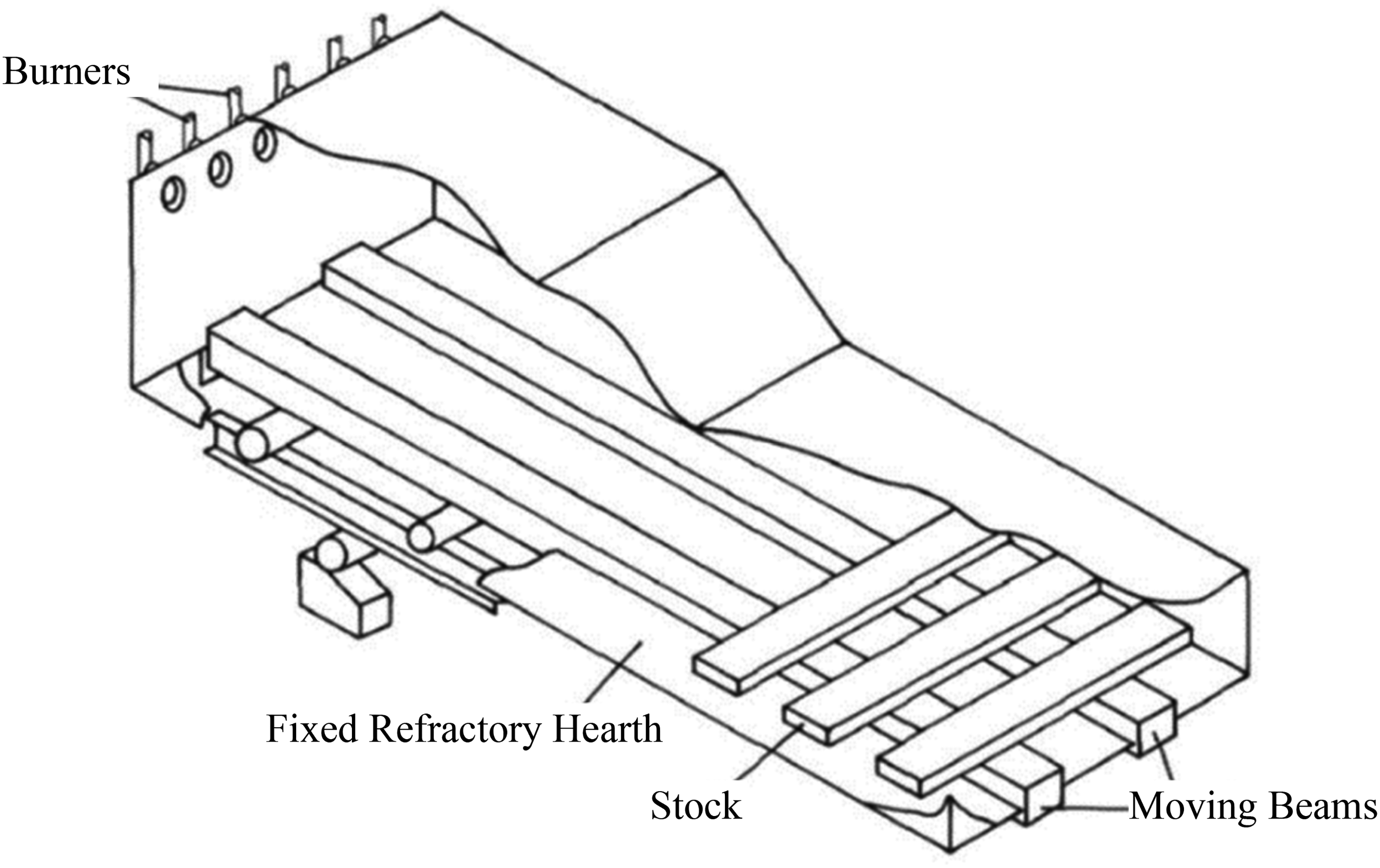
Schematic of a walking hearth furnace.
This type of furnace ensures that there is no sticking, which is one of the significant drawbacks of the pusher type. Additionally, material damage and hearth wear are kept to a minimum due to fewer contact points. However, this system is known to have a complex design. Hence, it leads to a higher capital cost. 7
The mode of heat transfer to the workpiece in either of these furnaces would entirely depend on the heating type used for the specific reheat furnace. 7 For example, walking hearth-type reheat furnaces are used with natural gas-fired burners, and heat is transferred to the billets via radiation and convection. 8 In contrast, induction heaters provide surface heating from induced eddy currents, which is conducted towards the core of the workpiece. 9
Once the required temperature for rolling is achieved, it is held for a suitable period to achieve homogenisation across the billets before being discharged. The discharge temperature is generally calculated based on these factors and the metallurgical properties desired in the product.
10
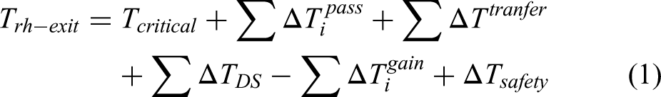
Hence, these conditions may vary depending on the specifications of the desired product. Ginzburg et al. used a heat balance (see equation (1)), which estimates the exit temperature.
10
Ginzburg et al.
10
suggest that a reverse calculation of this would provide an understanding of the critical temperature, which accounts for any losses the workpiece undergoes in terms of convection, radiation, and other heat transfer losses. However, this may not be highly reliable as the behaviour of heat within the workpiece itself is based on other factors, such as the material properties itself. Additionally, it is essential to note that since Ginzburg et al. do not consider the variation in heat loss, this equation is only applicable when the assumption of a steady-state system is applied.
10
Heat balance
Heat balance studies provide a basis for understanding heat transfer within the reheat furnace. Several studies looked at the energy efficiency of reheat furnaces through heat balance studies.11–13 Ertem et al. 11 investigated the potential for improving the specific energy in Eregli Iron and Steel Production Plants. 11 Using an energy input and output analysis, the losses of the system were analysed. It was understood that the thermal efficiency of the slab furnace was 64.26%. The hot charging temperatures were increased, and the remaining flue gas sensible heat was recovered through recuperation. Ertem et al. 11 found that the significant loss was through flue gas, accounting for 31.6% of the total energy, followed by surface and gap losses. However, there were other losses that the author could not quantify, which was approximately 6.7% of the total energy. 11
Manatura and Tangtrakul 12 investigated a reheating furnace with regenerative burners and identified that the specific energy consumption of the reheating furnace was 1042 MJ/t. 12 The furnace efficiency was calculated to be 80.1%. It was clear that the use of regenerative and recuperative systems in place provided at least a 43% improvement in efficiency. Other studies investigated energy-saving mechanisms by simulation. Si et al. 13 evaluated the furnace' energy efficiency and analysed the feasibility of waste heat recovery. Si et al. used the Process Heating Assessment and Survey Tool to determine the overall efficiency as 60%. 13 The most considerable losses were recorded as the loss of energy through flue gas, accounting for 29.5%. 13 Hence, the study concluded that it is ideal to heat the slab to 315 °C at charging to obtain maximum efficiency. Chen et al. 14 studied the energy consumption and performance of reheat furnaces. Figure 3 shows the variation in energy consumption with the heating rate. The author used a combination of numerical and experimental analysis to observe the effect of the production rate on the utilisation of fuel. The practical study consisted of quantifying the percentage of energy that fuel combustion produced. It was concluded that the combustion of fuel provided 80% of the heat, whereas 15.7% of the heat was from the hot flue gas. 14 Further measurements revealed that heat exchange and recovery efficiencies in the recuperative zone were 86.7% and 47.8%, respectively. 14
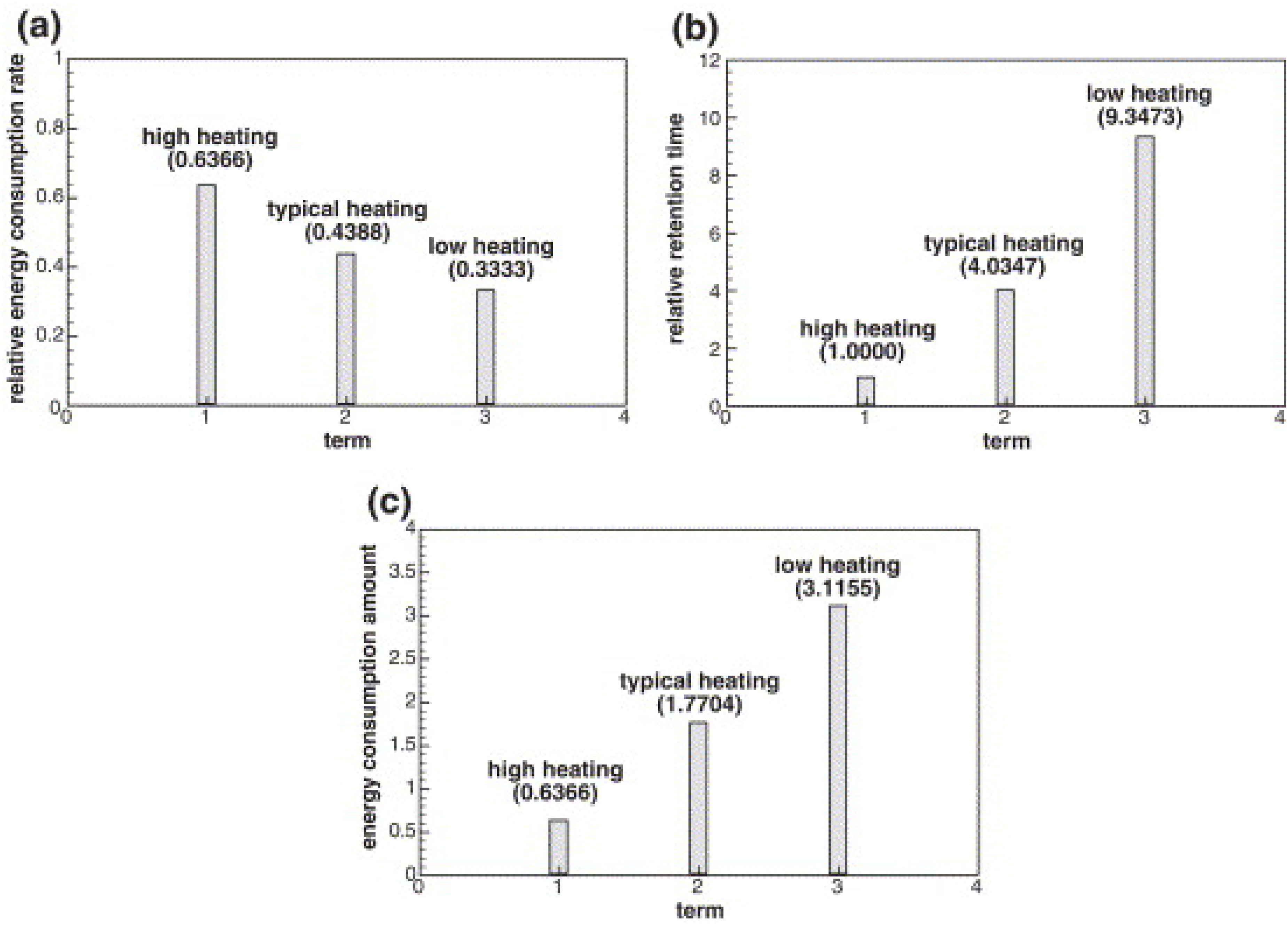
(a) Energy consumption change, (b) relative retention time, and (c) energy consumption amount with heating rate. 14
In these studies, given in the literature by Ertem et al., Si et al., Chen et al., and Manature and Tangtrakul, energy efficiencies and other energy-saving opportunities were determined for reheating furnaces.11–14 However, these studies did not consider the variation in discharge rates and their impact on the variation in efficiency. The development of a heat balance model validated with multiple thermal surveys will provide a clear view of the most suitable conditions for operating the reheating furnace.
The heat balance model developed by Stanford et al. 5 provided a basis for understanding heat loss in the reheat furnace at Laverton. The furnace' current performance was calculated by measuring its surface temperatures and oxygen concentration. To accurately investigate how the mill' production rate affected the furnace' thermal efficiency, Stanford et al. 5 first collected data at discharge rates of 50 tph, 70 tph, 86 tph, and idle (0 tph); then, used the infrared imager Flir E60 to record temperature data from the surfaces. However, existing plant instrumentation was used to determine the temperature of charging/discharging billets as well as flue gas temperatures. In producing the energy balance, the control volume included the furnace, recuperator, and associated ducting. The energy provided to the furnace was the result of the combustion of natural gas with air. The energy supplied by this process was determined using the enthalpy of combustion to establish natural gas' lower heating value.
Energy input data included heat in billets, combustion air, water seals, natural gas, and output energy data. The temperatures of discharging billets, leaks, flue gas, and energy lost through furnace surfaces were collected for a range of discharge rates (50 tph, 70 tph, 86 tph, and idle). Figure 4 shows the results and 86 tph and 70 tph discharge rates. A key conclusion by Stanford et al. 5 showed that the thermal efficiency of heating billets increased with a higher discharge rate. Additionally, the flue gas remained the most significant mode of heat loss, approximately 19% of the total output distribution of heat, assuming no unknown losses occurred. 5
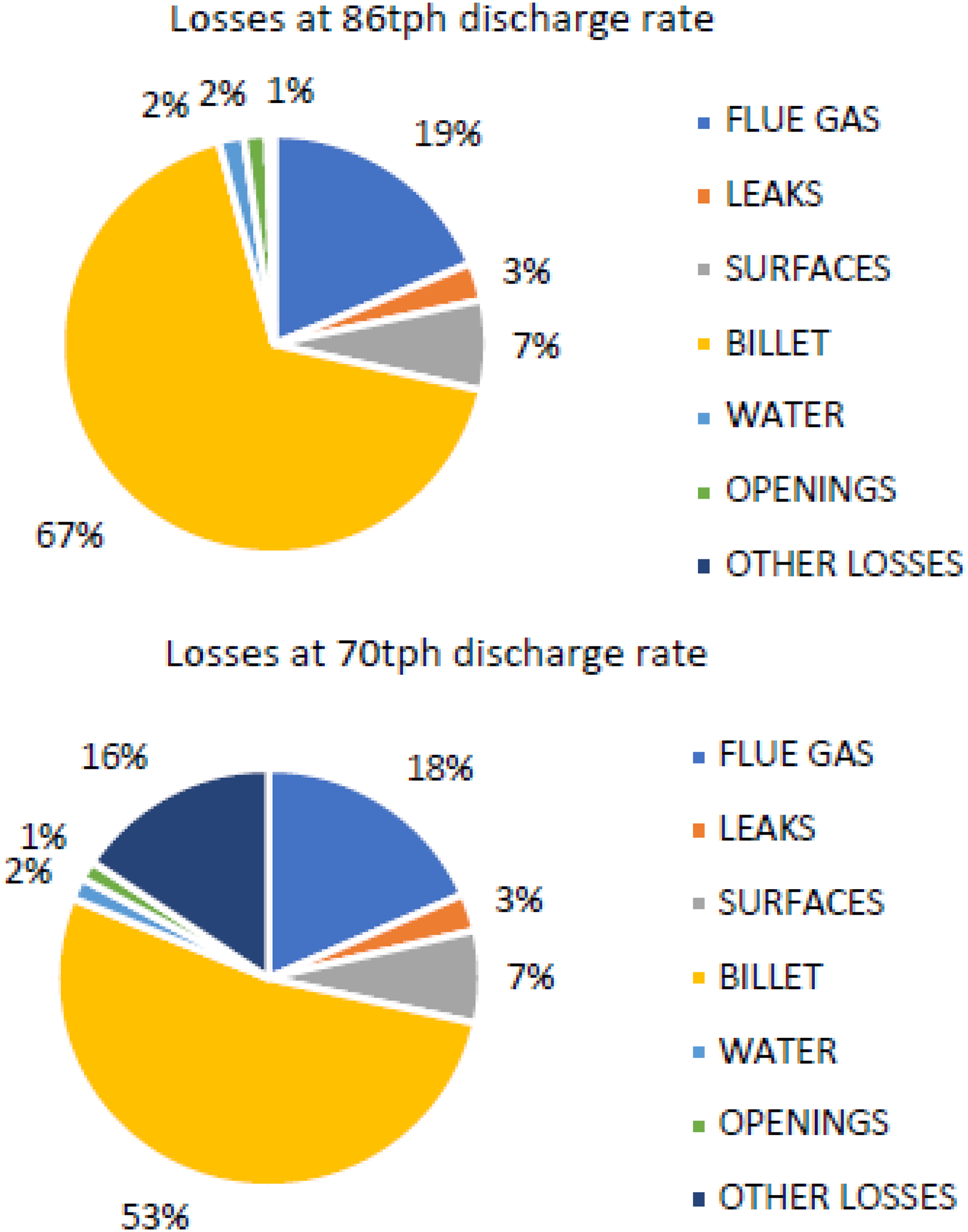
Heat distribution at 70 tph and 86 tph. 5
However, the model developed by this study had some shortcomings, including a significant number of unknown losses at 50 tph and 70 tph, averaging about 14.5% of the total losses. 5 The possible reasons for the unknown losses can be due to (1) broad estimation of leaks, (2) inaccurate surface losses due to the unevenness of roof temperatures, which can be due to cracks and general wear, and (3) significant losses in combustion air ducting between recuperator and furnace.
Chen et al. 14 estimated that through plant trials using thermocouples, heat loss through flue gasses accounted for roughly 30%, which is why it is beneficial to consider mechanisms by which this heat is recovered. 14 The graph in Figure 5 shows that most of the heat is transferred to the slab, but more than 50% of the energy is lost between surfaces and flue gas.
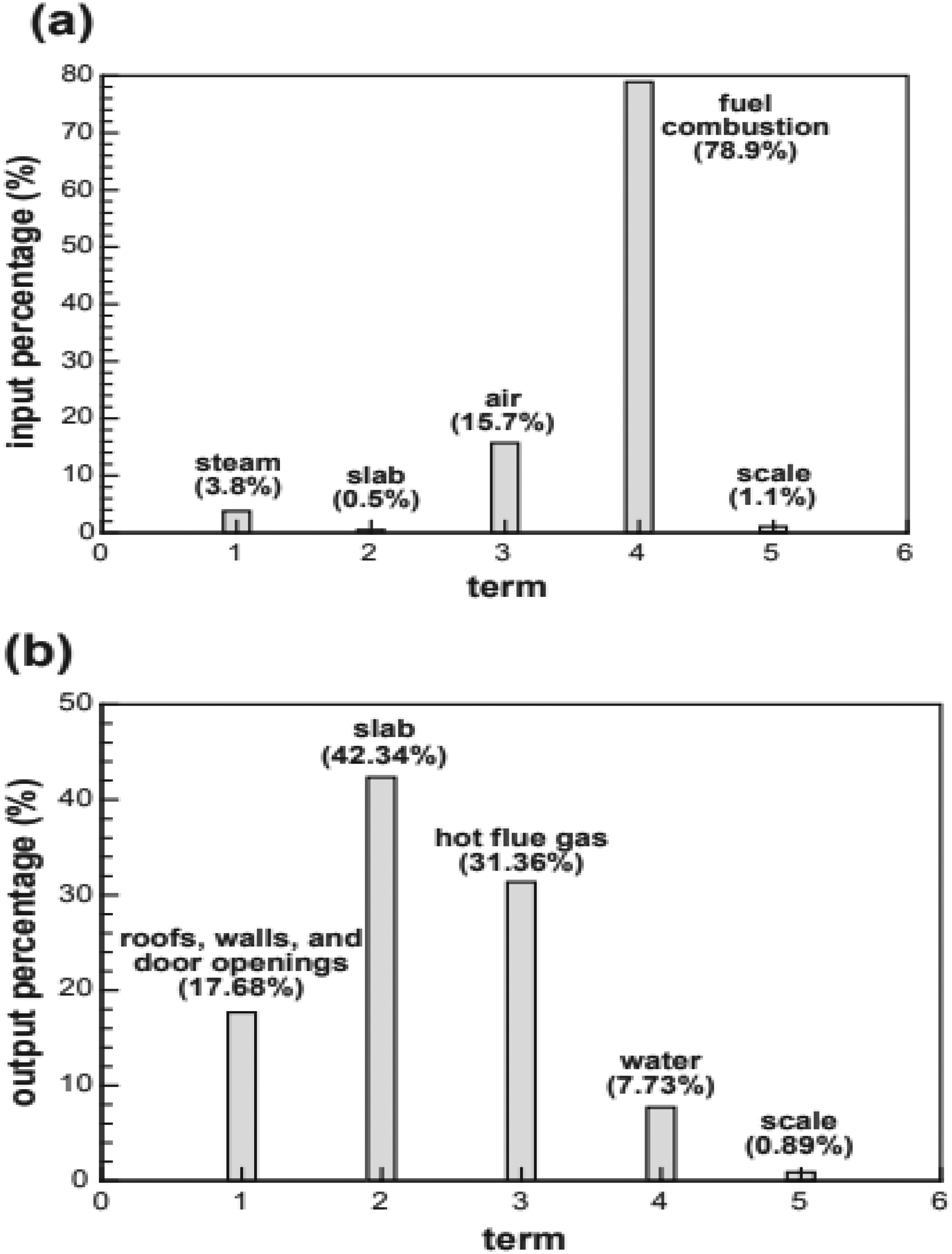
Input (a) and output (b) of heat percentages. 14
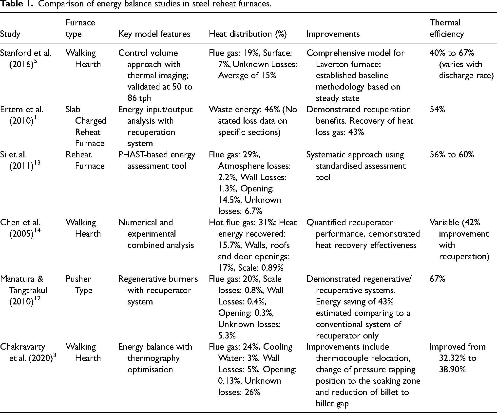
A specific technology for this very application is the recuperator. This mechanism transfers heat from the flue gas to the combustion air. Newer technology integrated the recuperative technology into the burner, which helps reduce any further thermal losses. Using recuperative technology has been shown to reduce up to 47% of the heat lost through flue gas 14 (Table 1).
Comparison of energy balance studies in steel reheat furnaces.
Methodology
Furnace Description
The reheat furnace at Laverton Steel Mill features a useful length of 18.720 m and a width of 13 m between walls. It is designed to achieve a production rate of 80 to 92 metric tons per hour. To optimise thermal performance, the furnace is divided into five control zones, including preheating, heating, and three soaking zones. It currently processes billets with dimensions of 150 mm square and a length of 12,000 mm, accommodating a total of 78 billets at a charging pitch of 240 mm. Positioned on the buffer at the mill site, the furnace operates with an average energy consumption of 1.35 GJ per metric ton and a scale loss of approximately 1%. Furnace pressure is maintained at a set point of 12 Pa above atmospheric pressure, with oxygen levels monitored in the preheating zone using Geva oxygen sensors. Nitrogen oxide emissions are not measured. The furnace employs a natural draft chimney without an exhauster fan for flue gas evacuation.
The burner configuration consists of BLOOM 2180 burners distributed across the control zones. The details of burners included in the model:
Preheat Zone – 21 Bloom burners 2180 of 2.368 MJ/h
Heating Zone – 14 Bloom burners 2180 of 3.180 MJ/h
Soaking Zone – 2 X 6 Bloom burners 2180 of 0.955 MJ/h
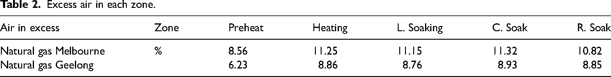
Combustion in the burners occurs with the Air to Gas ratio characteristics in stoichiometric combustion at 9.528 Nm3. The excess air is portrayed in Table 2.
Excess air in each zone.
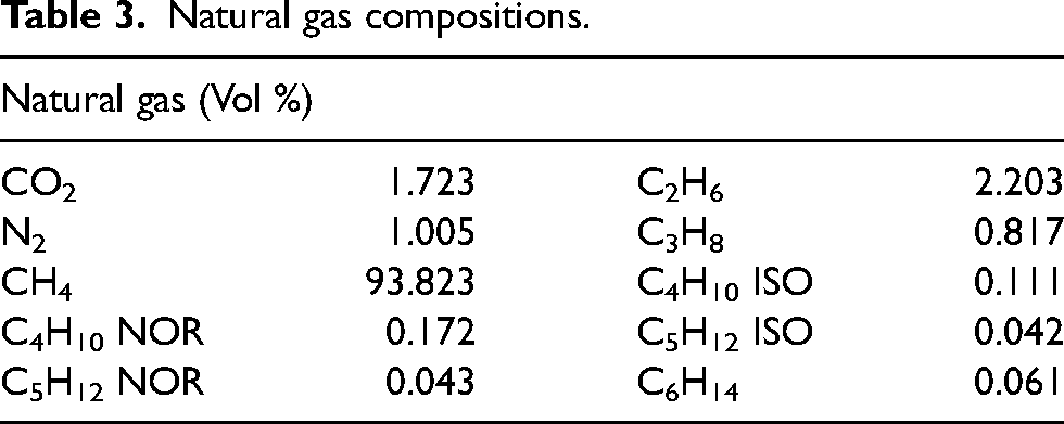
The natural gas composition is given in Table 3.
Natural gas compositions.
Data collection
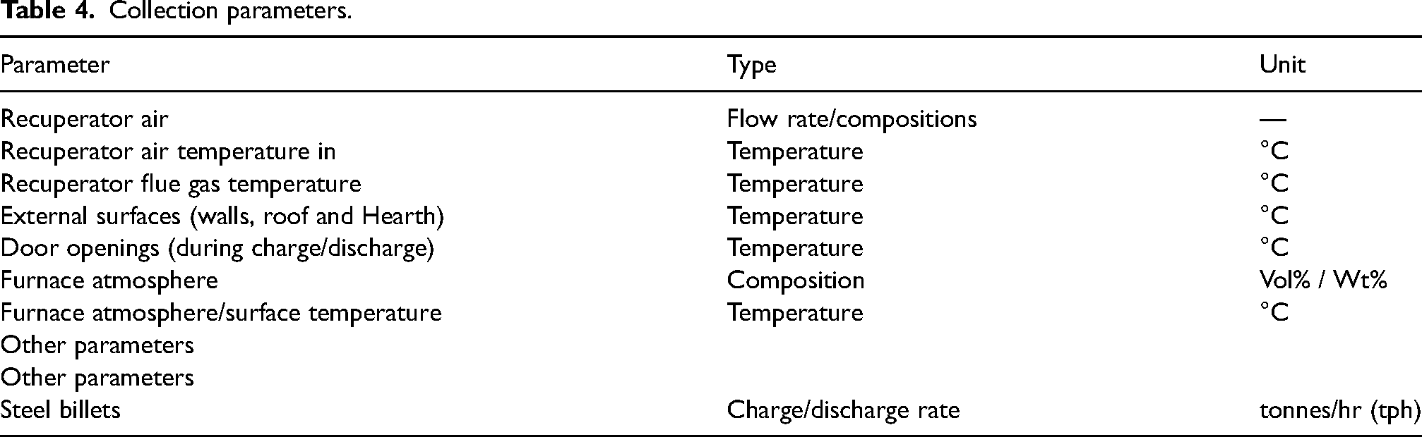
The model was created based on the input and output data obtained at 86 tph and 92 tph discharge rates. The data was collected through five thermal surveys that were used to measure the variables given in Table 4.
Collection parameters.
Numerical calculation
The energy balance was modelled as a steady-state system with a control volume, as shown in Figure 6, encompassing the furnace and its various zones as a single system. The steady-state assumption in reheat furnace modelling is well-founded based on three critical considerations that validate this approach for industrial applications. From an operational perspective, continuous furnaces maintain constant heat input rates throughout operation, with burners rarely shut off except during maintenance delays, while operating within narrow temperature ranges that inherently support steady-state approximations. Walking hearth furnaces specifically provide consistent material flow through hydraulic walking systems, ensuring relatively uniform thermal conditions that minimise transient effects. Time scale analysis further supports this assumption, as furnace thermal response times are significantly longer than individual charging and discharging cycles, requiring only constant slab velocity or consistent pushing periods to maintain steady-state conditions. Industrial furnaces typically achieve thermal equilibrium within standard operational timeframes, allowing for stable heat transfer analysis. The validity of steady-state modelling has been demonstrated through extensive validation studies against industrial furnace data, achieving average relative errors of only 3%, which provides strong empirical support for this approach. 15 This modelling framework enables the isolation and accurate quantification of individual heat transfer phenomena, facilitating precise energy balance calculations and optimisation strategies for reheat furnace operations. The combination of operational stability, appropriate time scale considerations, and validated modelling accuracy establishes the steady-state assumption as a robust and scientifically sound approach for reheat furnace thermal analysis.
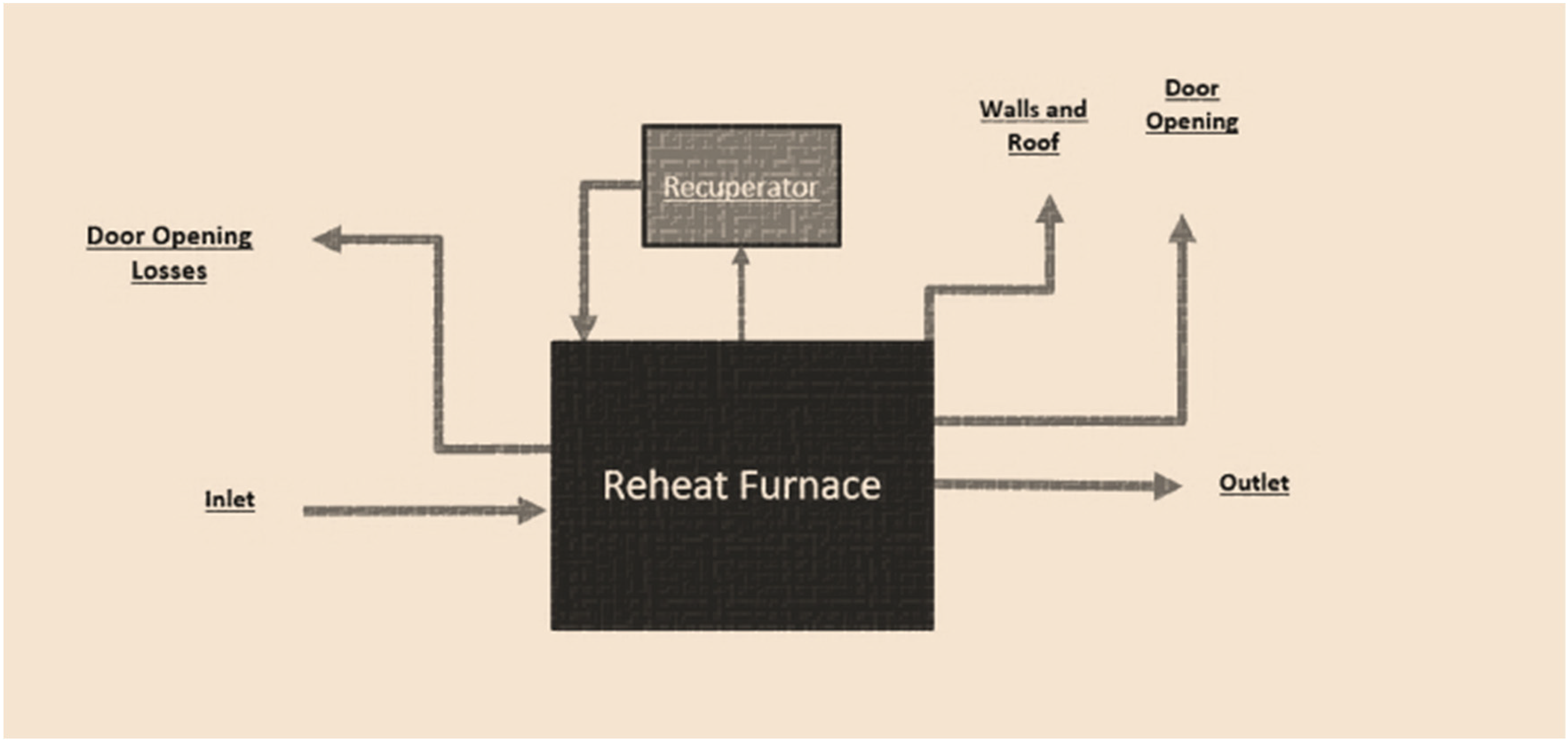
Control volume of the reheat furnace.
Hence this model has been solved analytically where convective losses are computed via Newton' law of cooling (equation (9)) with Grashoff and Rayleigh correlations, while radiative losses use the Stefan–Boltzmann law (equation (10)) with measured emissivities. Combustion heat input is determined by the Hayes & Algie enthalpy balance (equation (11)), and billet heating by a standard mCp/ΔT calculation (equation (13)). These equations are solved in sequence of combustion, surface losses, opening losses, and billet absorption to close the energy balance and yield reliable predictions of furnace performance.
Figure 7 portrays the reheat furnace walls subdivided into smaller segments, where measurements were obtained separately for each of these segments. This data was then used to create the average heat loss across the north, south, west, and east walls.
Segments of walls in the reheat furnace.
The measurements for the external surfaces of the reheat furnace were obtained through thermal imaging using a Flir E60 Thermal Imager camera. As this is highly dependent on the surface emissivity, the contact method portrayed by Usamentiaga et al. 16 was used to determine the surface emissivity.
Surface losses were quantified by segmenting the furnace exterior and measuring temperatures on each segment. Figure 7 shows how the walls and roof were divided into discrete segments for measurement. The thermal imager (FLIR E60) was used to obtain the surface temperatures of walls, roof, and hearth. For each segment, convective losses were calculated by Newton' law of cooling (equation (9)) and radiative losses by Stefan–Boltzmann' law (equation (10)) using the measured temperature and emissivity. Crucially, the hearth was treated as a separate surface. A thermal image of the north-east section of underneath the hearth was captured, and its high temperatures were used in the same heat loss equations. This procedure isolated the temperature recorded underneath the hearth, independent of the wall–roof segments. In the results, the most significant surface losses were indeed on the north wall and beneath the hearth, confirming that our method successfully distinguished the hearth' contribution from the general surface losses.
Numerical calculations
The infrared camera (FLIR E60) is based on the theory of thermography.16,17 The electromagnetic spectrum is divided into different wavelength regions called bands, as seen in Figure 8. There is not necessarily any fundamental difference between radiation in the other bands of the electromagnetic spectrum. 18 The only differences are those due to differences in wavelength.
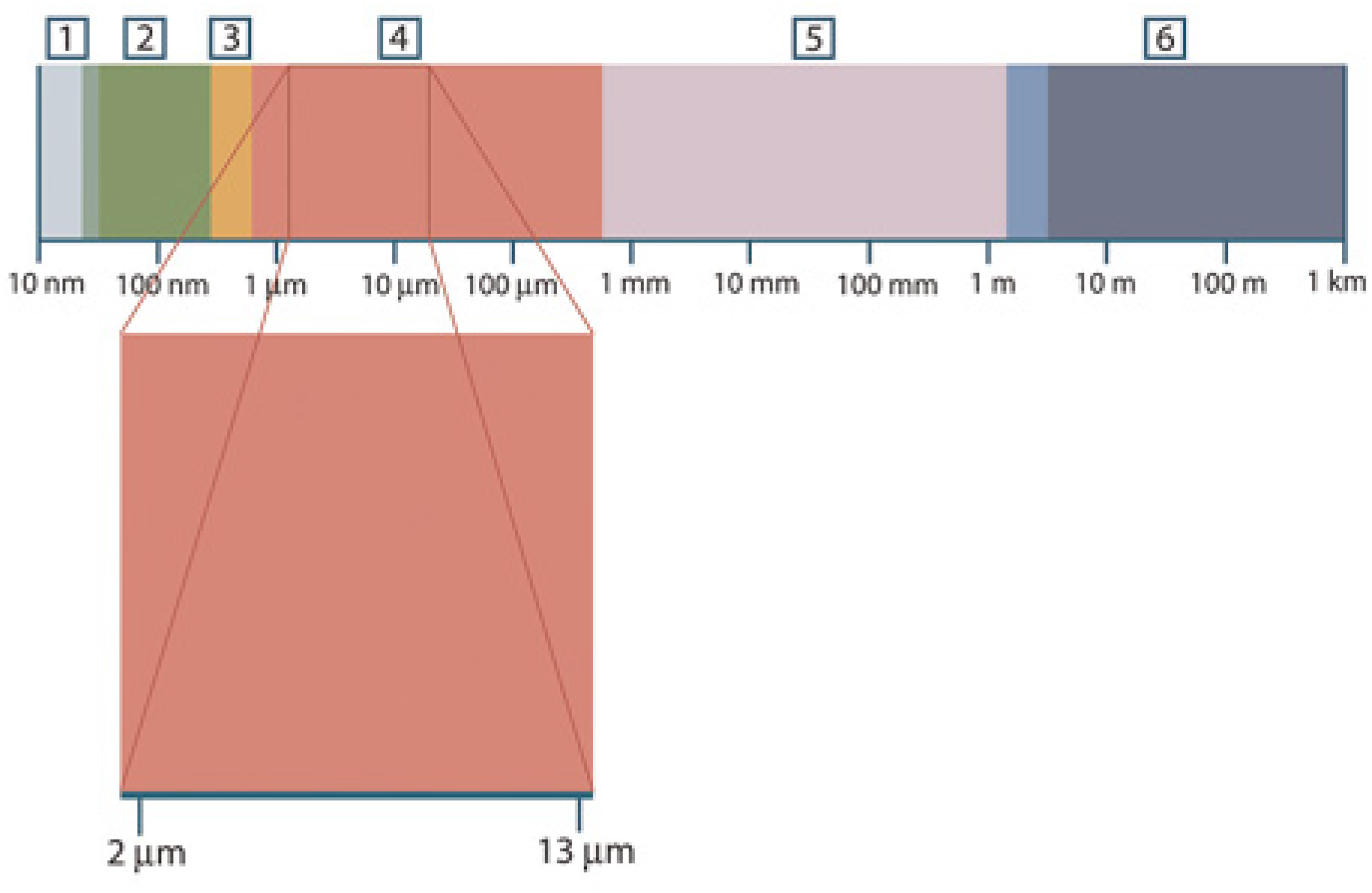
Wavelength regions. 17
Thermography uses the infrared spectral band. The short-end boundary lies at the limit of visual perception in the deep red. Meanwhile, at the long wavelength end, it merges with the microwave radio wavelengths. Hence, it is often further divided into four smaller bands, the boundaries of which are also arbitrarily chosen. This includes the near infrared (0.75 to 3 μm), the middle infrared (3 to 6 μm), the far infrared (6 to 15 μm), and the extreme end (15 to 100 μm).17,19
Three expressions are considered to describe the radiation emitted from a blackbody. Planck' law was put forth by Max Planck, describing the spectral distribution of the radiation from a blackbody.
20
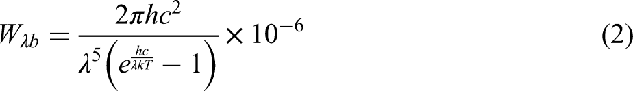
When graphically plotted for various temperatures, Planck' formula produces a range of curves given in Figure 9. The spectral emittance is zero at
Blackbody spectral radiant emittance according to Planck' law, plotted for various absolute temperatures. 17
The differentiation of Planck' formula17,20 with respect to 
Equation (3) gives Weins' formula, and it expresses mathematically the common observation that colours vary from red to yellow or orange as the temperature of a thermal radiator increases. The wavelength of the colour is the same as the wavelength calculated for
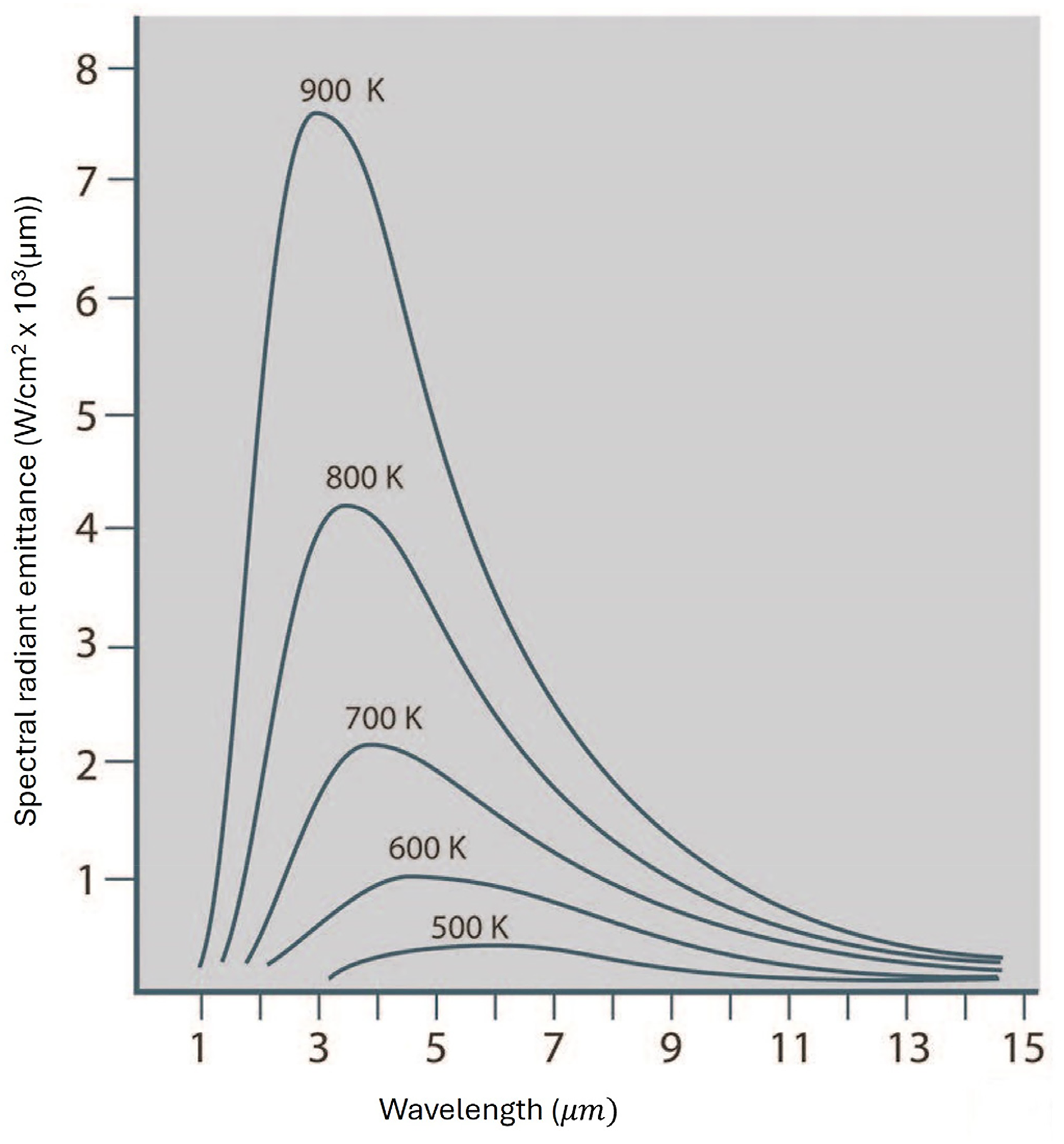
As mentioned before, the camera receives radiation not only from the object itself but from its surroundings as well as the atmosphere itself. Hence, Figure 10 provides a basis for derived formulas that can be used to calibrate the camera to determine the object' temperature.
Camera calibration using radiation equations. 17
Assuming that the received radiation W from a blackbody source of temperature T source on short distance generates a camera output signal U source that is proportional to the power input, we can express it as follows:
If the source is a greybody with emittance
Hence, the collected radiation can now be expressed in three power terms:
Emission from the object = Reflected emission from ambient sources = Emission from the atmosphere =
The total radiation power can now be expressed as follows:
Considering constant C and replacing CW products with U of equation (4), we can obtain,
Thus,
Furnace surfaces
Following the data collection, an energy balance can be performed for each of the different zones, including the recuperator, using the Grashoff number given in equation (8).5,21 This is used to represent the ratio of a fluid' viscous forces to its buoyancy forces.
The Rayleigh number can be obtained using the Prandtl number, which gives the relationship between a fluid' buoyancy forces and its thermal diffusivity. Hence, the surface' average heat transfer coefficient is obtained through natural convection.5,21 Newton' law of cooling, given in equation (9), can be used in each of the zones to obtain this data.
Radiation heat loss can then be identified using the Stefan–Boltzmann Law in equation (10) and emissivity calculated previously, which is used in the thermal camera.5,21,22
Combustion process
To determine the amount of energy provided by the combustion of natural gas in the furnace, the energy balance process described by Hayes and Algie was used. As described by equation (11), Hayes and Algie
22
define the heat provided by combustion in a steady-state system as the change in enthalpy between the products exiting the furnace to the reactants entering it. As the products do not condense before exiting the furnace, moisture was assumed to be in its vapour state, therefore leading to the calculation of natural gas' lower heating value of 33 MJ/Nm3.
The natural gas compositions used are given in Table 5.
Compositions of natural gas.
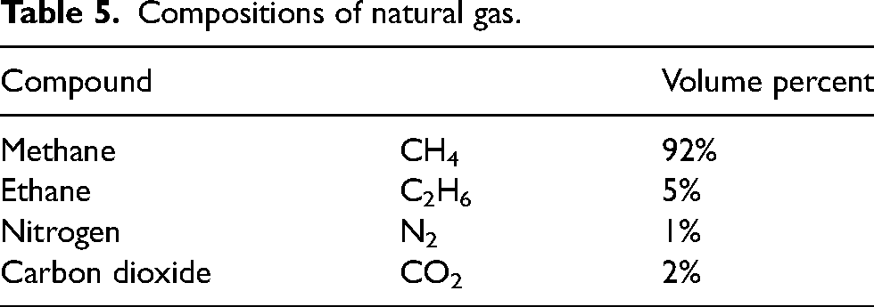
The enthalpies required to perform the combustion energy balance were obtained from the work of Çengel and Boles. 21 As the control volume includes the recuperative zone, the enthalpy of the air entering the system is taken at 15 °C. In contrast, the enthalpy of the products is taken at the recuperator exit, which is approximately 450 °C.
Openings
The furnace has eight central openings, namely the charge and discharge door, which open to allow billets to enter and exit the furnace, as well as eight fixed openings, which will enable the charge and discharge arms to enter the furnace to move billets on and off the rollers. The charge openings are at the cold side of the furnace (approximately 1000°C), while the discharge openings are at the hot side of the furnace (approximately 1200°C). Each opening was treated as losing energy only due to radiation and at the temperature of the zone it was present in. The amount of time that the charge and discharge doors were open was also calculated as a percentage and multiplied by their respective zone temperatures.
Steel billet
Energy absorbed and subsequently removed from the furnace by the steel billets was calculated by assuming a constant, steady flow of the system. Heat transfer was then calculated, as shown by equation (13). The specific heat used was taken from Çengel and Boles.
21

Results and discussion
Studies were conducted at the steel mill in Laverton; the energy balance was then developed to calculate energy distribution. The inflow and outflow of energy were categorised based on the input energy, the energy leaving in the discharged billet, surface losses, openings in the furnace, heat losses through the cooling water, leaks, and the flue gas.
Figure 11 shows the distribution of the energy, with most of the heat being transferred to the billet itself. The energy efficiency of the billet was estimated to vary between 30 and 50%, with the increasing discharge rate. This is in agreement with the work by Stanford et al., 5 Si et al. 13 and Chen et al. 14 The heat balance shows that most of the energy is transferred to the steel billets; however, a large number of losses were observed through the flue gas and the surfaces. The most considerable surface losses were observed on the North wall and under the hearth.
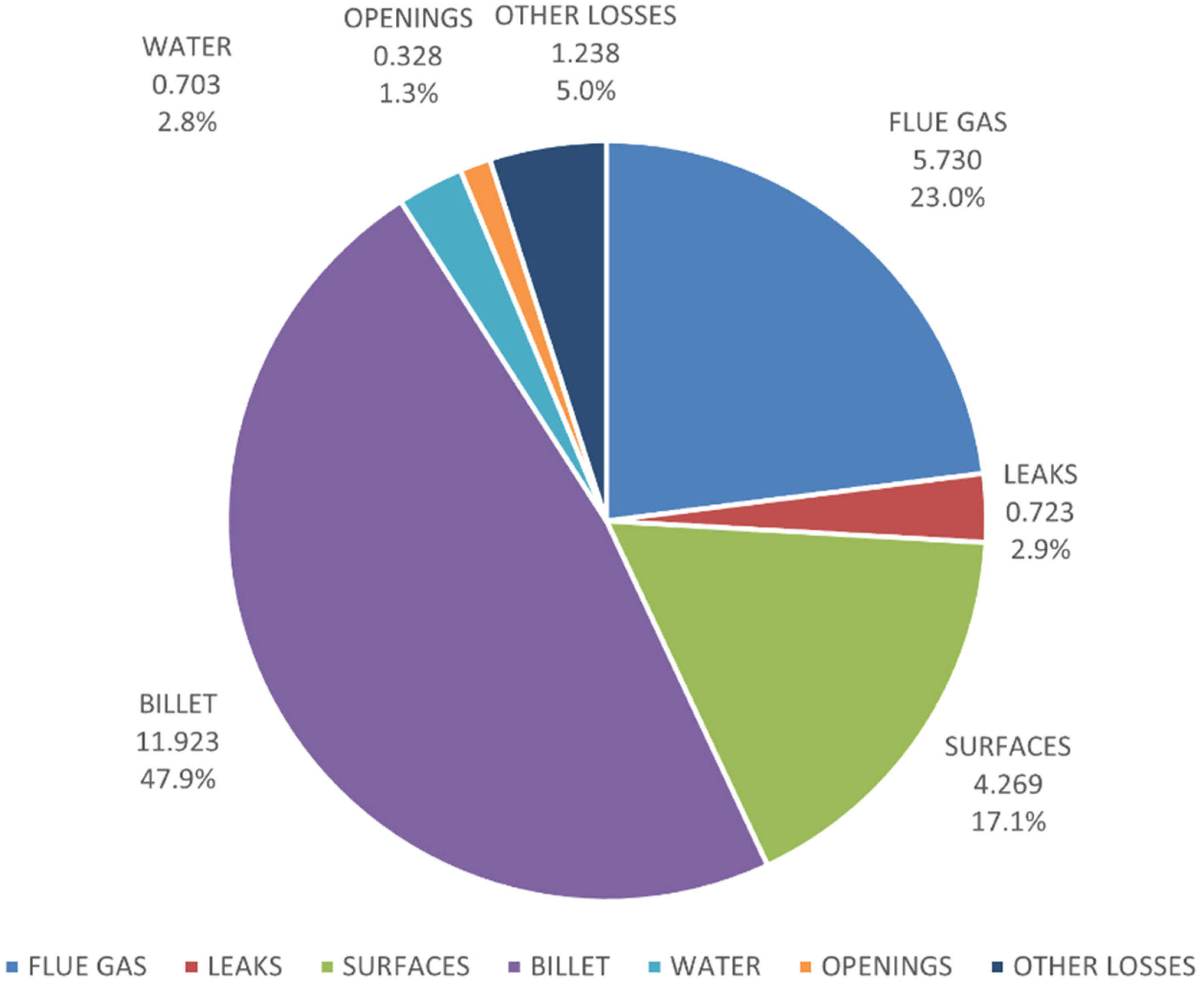
Heat distribution at 86 tph.
Hearth (north-east)
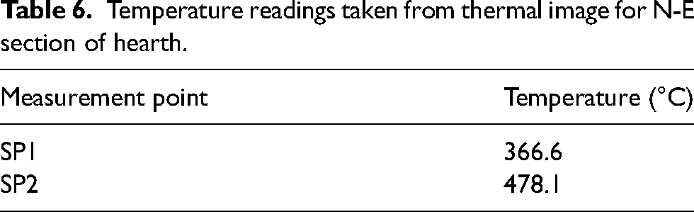
This model was able to significantly improve upon the unknown losses which were previously recorded by Stanford et al. 5 By carefully measuring each loss stream (flue gas, surfaces, openings, cooling water, leaks, etc.), we largely closed the energy balance. The study notes that some small discrepancies may arise from measurement uncertainties, for e.g. in cooling water temperatures or IR emissivity. From the many data points used in this thermal survey, particular interest was shown towards readings obtained underneath the furnace, as shown in Table 6 and Figure 12. This was mainly because the relatively high temperatures, approximately 480°C, were observed underneath the hearth. According to Pérez et al. 23 when refractory deteriorates, they lose their insulating properties, allowing heat to conduct through the hearth and increase temperatures underneath. Insulation is critical in maintaining temperature gradients, and any breakdown in the refractory layer exposes the underside to excess heat. This breakdown can occur due to chemical corrosion from steel oxidation or mechanical stresses during furnace operations.
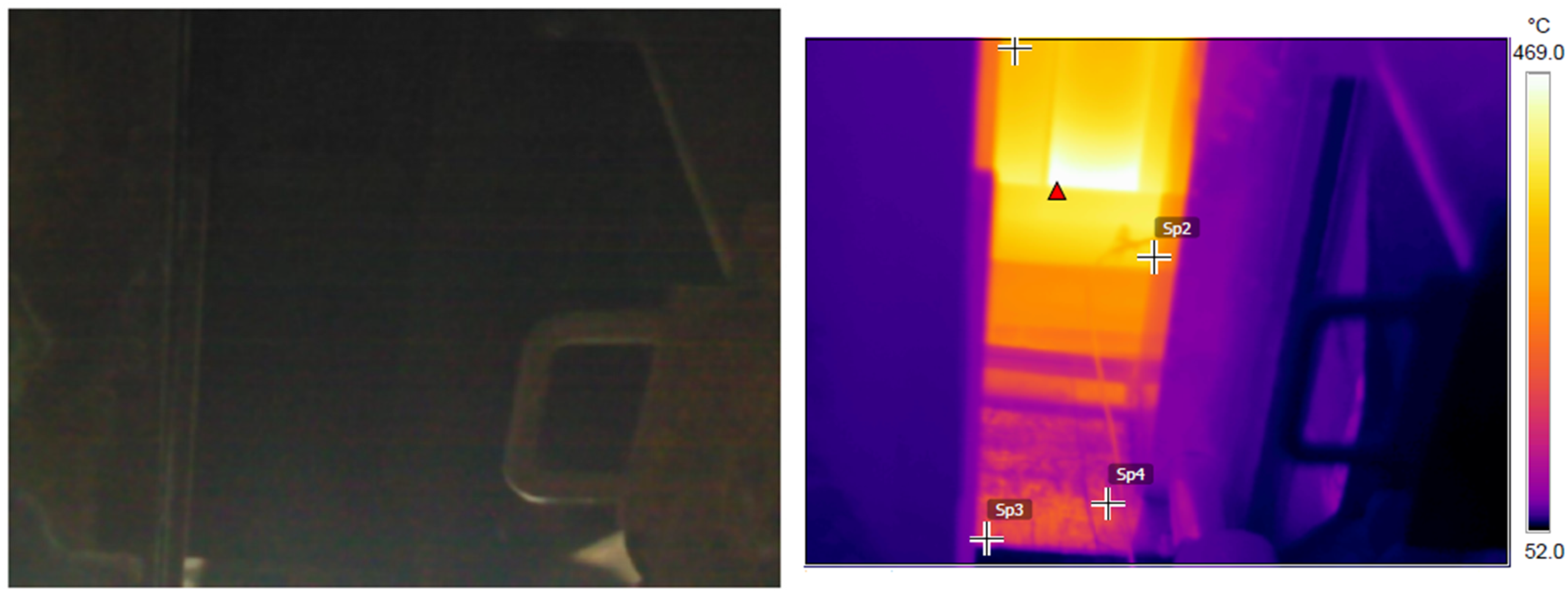
Thermal image for north-east section of hearth.
Temperature readings taken from thermal image for N-E section of hearth.
Improper combustion control is another contributing factor, as highlighted by Zhao et al. 24 Burners that must be correctly aligned or adjusted can cause uneven flame distribution within the furnace chamber. Instead of heating the stock uniformly, flames and hot gases may be misdirected, allowing heat to accumulate near the hearth and radiate downwards. Excess fuel or air supply may also lead to localised overheating, increasing the temperature beneath the hearth. The transfer of heat within the furnace also plays a significant role in this issue. Wang et al. 25 explored that reheat furnaces primarily operate based on radiant heat transfer, but conductive heat transfer through the furnace structure can also impact hearth temperatures. When the thermal conductivity of the hearth is high or compromised insulation exists, heat that should remain within the furnace chamber can pass through to the underside, raising temperatures there. The study further explains that radiation from overheated areas within the furnace can exacerbate this problem, as energy not absorbed by the stock or reflected is transferred through the hearth.
Heating efficiency
Heating efficiency in steel reheat furnaces is defined as the ratio of the useful heat absorbed by steel to the total energy input, expressed as a percentage. It reflects the furnace' ability to convert fuel energy into the thermal energy required to raise billets to the desired processing temperature. Efficiency is influenced by factors such as heat losses through flue gases, furnace walls, and openings, as well as combustion conditions and billet preheating.
Production heating efficiency ranged from 52.8% at 92 tph to 35% at 70 tph discharge rate. The heating efficiency and the discharge rate cannot be described in a linear relationship. However, it can be hypothesised that the heating efficiency improves with the increasing discharge rate. This is agreeable with the work done by Stanford et al.
5
The increment in efficiency decreases with the increasing discharge rate. So, as the discharge rates move up from 50 tph to 92 tph, the gradient of the graph in Figure 13 can provide the rate of change in efficiency
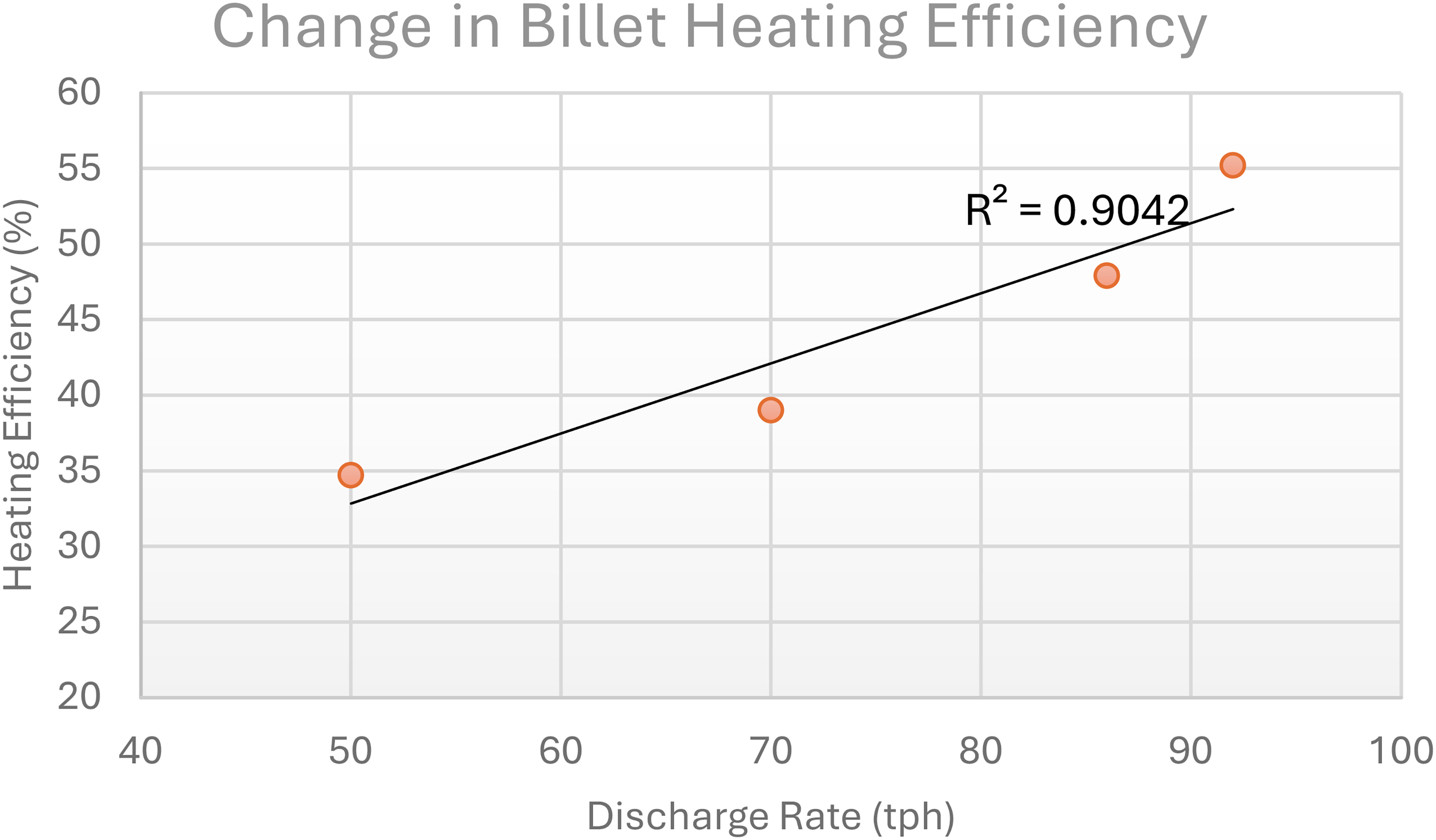
Variation in billet efficiency.
The graph in Figure 14 shows the polynomial relationship in the order of 2, which can be considered between 50 tph and 92 tph to improve the fitting of the curve. The equation of this curve can be used to predict the variation in the discharge rate.
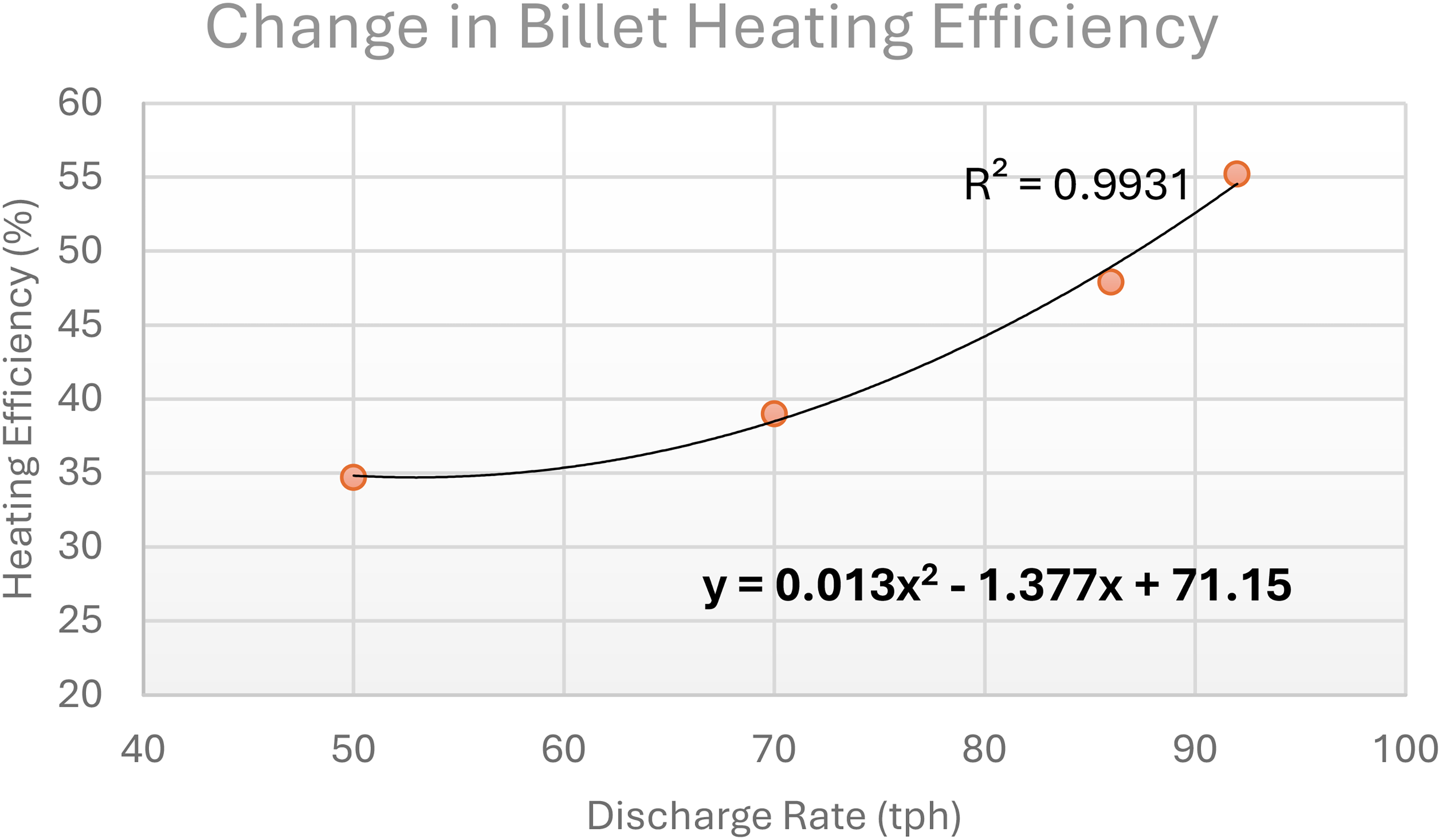
Polynomial relationship for billet efficiency.
The energy balance model can be utilised as a valuable tool in predicting the performance of the reheat furnace under different conditions to identify the most economical and practical configuration for it to function.
However, the model can be improved further by,
A more extensive dataset can be incorporated to validate the model. Additionally, a continuous monitoring system connected to a data logger could work hand in hand with the model to provide a live monitoring system. The temperature data for losses in water can be recorded more accurately if a direct measurement is taken rather than taking readings directly off the pipes. This might be a potential cause for some of the unknown losses. Thermocouples may be used in place of the thermal imaging camera that was used, which would reduce any disturbance that the thermal imager would encounter with radiation from the surroundings.
Conclusions
This research project was undertaken at Infrabuild' Laverton steel plant. Furnace variables were measured at 86 tph and 92 tph to understand the thermal efficiency of the reheat furnace. This data was then used to construct a model that can quantify the distribution of heat under alternate conditions, such as different discharge rates and warm charging temperatures. The study aimed to understand the distribution of heat within the reheat furnace so that energy could be better utilised to heat steel billets.
The results indicated that the furnace was able to utilise fuel much more efficiently at higher discharge rates. Depending on the discharge rate, the heat transferred to the billet varied from 30% to approximately 50%. Flue gas remained the most significant contributor to the losses, averaging about 25% depending on the discharge rate. This was followed by surface losses, which were substantially higher than expected, approximating up to 18%. The most considerable surface losses were observed underneath the furnace, reaching temperatures up to 500 °C. This can be due to multiple reasons, such as heat transfer dynamics, insulation quality, and furnace design and maintenance. 26 Poor insulation or refractory degradation can lead to heat loss through the hearth, resulting in elevated temperatures underneath it. Additionally, improper combustion control or burner misalignment may cause uneven heating and hot spots beneath the hearth, as excess heat radiates downwards instead of being directed effectively towards the stock. Conductive heat transfer from the furnace chamber and radiation from overheated areas can also raise temperatures beneath the hearth, reducing overall furnace efficiency. Further assessment is required to suggest the most probable cause from the above conclusions.
Careful measurement of surface losses is important and there is some basis to implement permanent monitoring systems of wall losses. Further studies incorporating these recommendations and more to model heat balances in steel reheat furnaces would help advance knowledge of the best energy utilisation in steel reheat furnaces. Additionally, integrating predictive models for environmental emissions such as NOx prediction systems would provide a more comprehensive approach to sustainable steelmaking operations. 27
This study presents a comprehensive heat balance model for a walking hearth reheat furnace that quantifies surface losses beneath the hearth reaching 500°C, demonstrating that these losses contribute significantly more to the total energy output than previously recognised in industrial furnace modelling. The validated model provides a practical framework for identifying optimal discharge rates (86 to 92 tph) that maximise heating efficiency from 35% to 52.8%, enabling targeted energy optimisation strategies for secondary steelmaking operations.
Footnotes
Acknowledgements
The authors wish to acknowledge funding through the Victorian Hydrogen Hub (VH2) and the support of Infrabuild Steel.
Declaration of conflicting interests
The authors declared no potential conflicts of interest with respect to the research, authorship, and/or publication of this article.
Funding
The authors received no financial support for the research, authorship, and/or publication of this article.