
Abstract
Until recently, analyses and control strategies of the remelting processes assumed that in the high temperature region the process current is completely contained in the path between the electrode and the ingot. It is now generally recognised that there is also a second path, electrode to mould (‘mould current’), which plays a significant role in both the process heat balance and process parameters, hence influencing the ingot structure. This report critically reviews the published experimental evidence and process analyses relating to the effect. In both the main processes, electroslag remelting and vacuum arc remelting, the mould current plays an important part in establishing ingot structure but in the present process operations it is neither measured nor controlled. It is postulated that further work directed towards control of the mould current is necessary for optimising reproducible ingot quality. It is further concluded that valid computational analyses of the processes must allow for the component of mould current.
Introduction
Many models have been developed for the purpose of describing the operation of the remelting processes.1–24 Until recently, the structure of the algorithms developed in the models has been based on the concept that the process current is carried entirely by the path between the electrode melting face and the ingot pool surface. The earliest models of electroslag remelting (ESR) were basic heat transfer calculations, 2 subsequently progressing into CFD descriptions of thermal and fluid flows1,4 based on the above assumption. However, in both the vacuum arc remelting (VAR) process and the ESR, there is a division of current flow, splitting it between the two paths (electrode-ingot) and (electrode-mould). The ESR phenomenon has been recognised in practice for some time as illustrated by descriptions of experimental studies of the ESR process published in 1961, 16 1971, 25 1976 10 (Figure 1) and 1980.27,28 These reports demonstrate a current flow pattern in which there is a division between the paths (electrode-ingot) and (electrode-mould) detailing experimental results in which the mould current is measured and shown to depend on slag depth and slag composition. The addition of the mould current concept into the ESR model structure was not introduced until 2008. 9 Subsequent models of both ESR and VAR9–24 have included some form of assumption or measurement of the mould current effect.10,14,21,22,24 The equivalent effect of mould current in the VAR process was recognised in models at an earlier development stage 29 than in ESR modelling. The addition of the process component was due to observations that a process heat balance based on the assumption that the heat input is the total power supplied to the furnace could not be reconciled with practical results. A satisfactory balance was only obtained if a fraction of the power was considered to be lost through mould current. Recent models proposed for the VAR process13,19,21,22 all specifically include this aspect of the process.
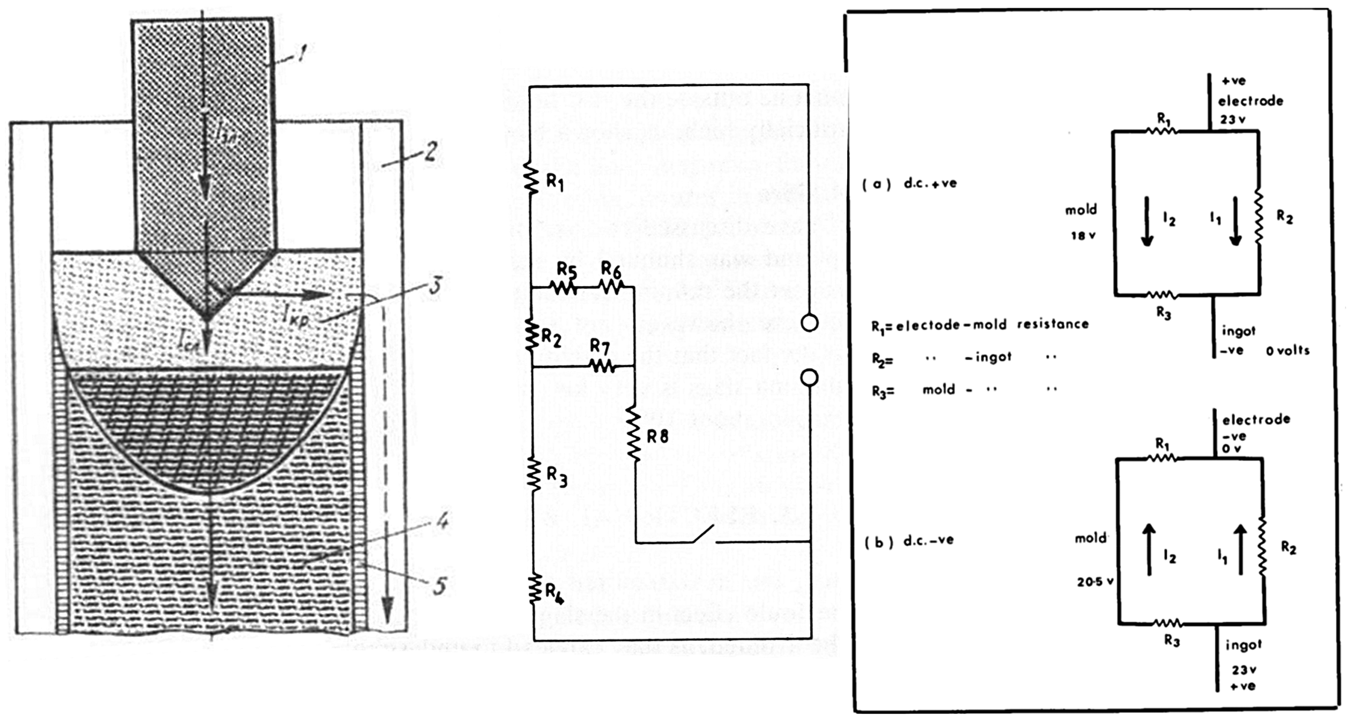
The mechanism leading to mould current and its influence on the process operation differs between ESR and VAR. The mechanism permitting mould current in the ESR process is generally treated in modelling studies as conduction through a resistance between the slag and the mould wall. The detailed conduction process has not been examined experimentally. The equivalent mechanism in VAR has been more extensively studied and both the magnitude and form of the mould current conduction have been defined on industrial-scale furnaces. In both ESR and VAR, the magnitude of the mould current and its relation to ingot structure appear to vary with the alloy being melted. Although the presence of mould current in the processes has been indirectly acknowledged in industrial ESR operations, there are no reports of its systematic study on an industrial scale. One such study has been carried out on the VAR process 30 demonstrating that mould current is a large factor in the power efficiency of the process. It is clear, however, that the presence of mould current in routine industrial operations is not a process instability; it is a normal feature of both ESR and VAR.
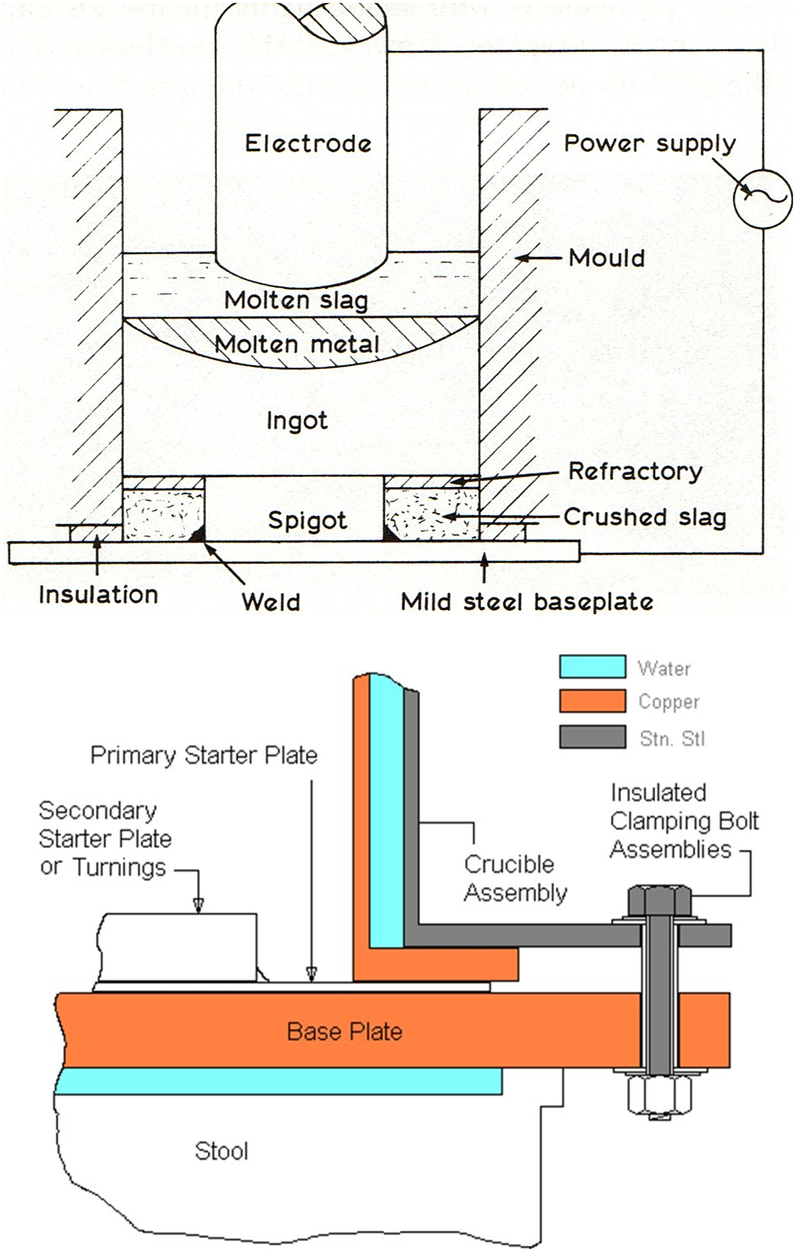
Mould current in the electroslag remelting process
Experimental and practical experience
Mould current is not routinely measured in industrial ESR processes. Reports containing measurements of the effect are restricted to experimental work on small-scale equipment which was designed specifically to measure it.27,28,31 In the most extensive account, 28 Kusamichi measured the mould current for several slag compositions, confirming the previous process measurements of Medovar. 10 The data in both cases indicates that the magnitude of the current is a function of the CaF2 content of the slag (Figure 2).
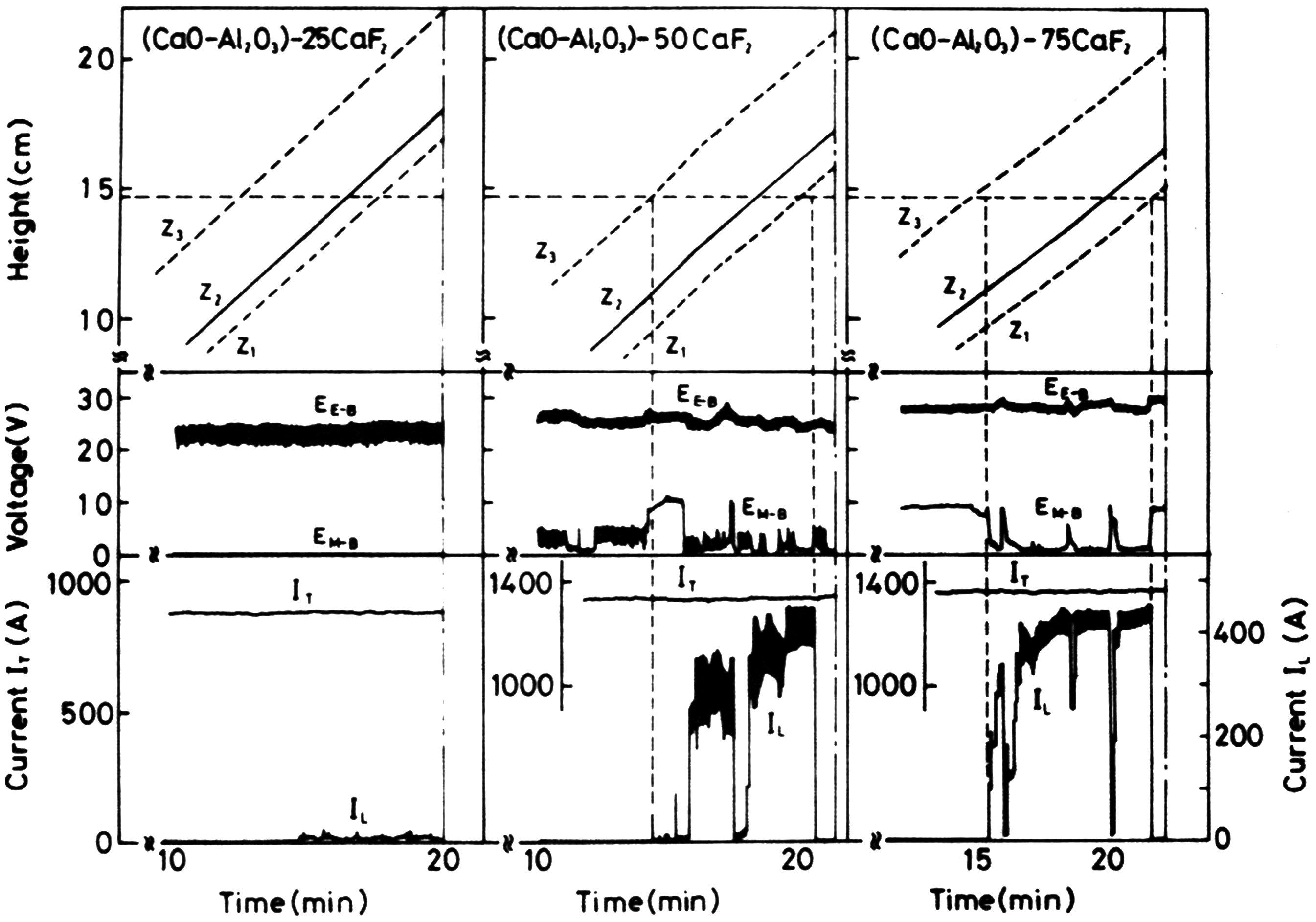
Mould current experimentally determined in a laboratory-scale ESR furnace, Kusamichi 28
Kusamichi also calculated the slag/mould heat transfer coefficient and found it to be a function of the slag CaF2 content paralleling the mould current behaviour (Figure 3(a)).
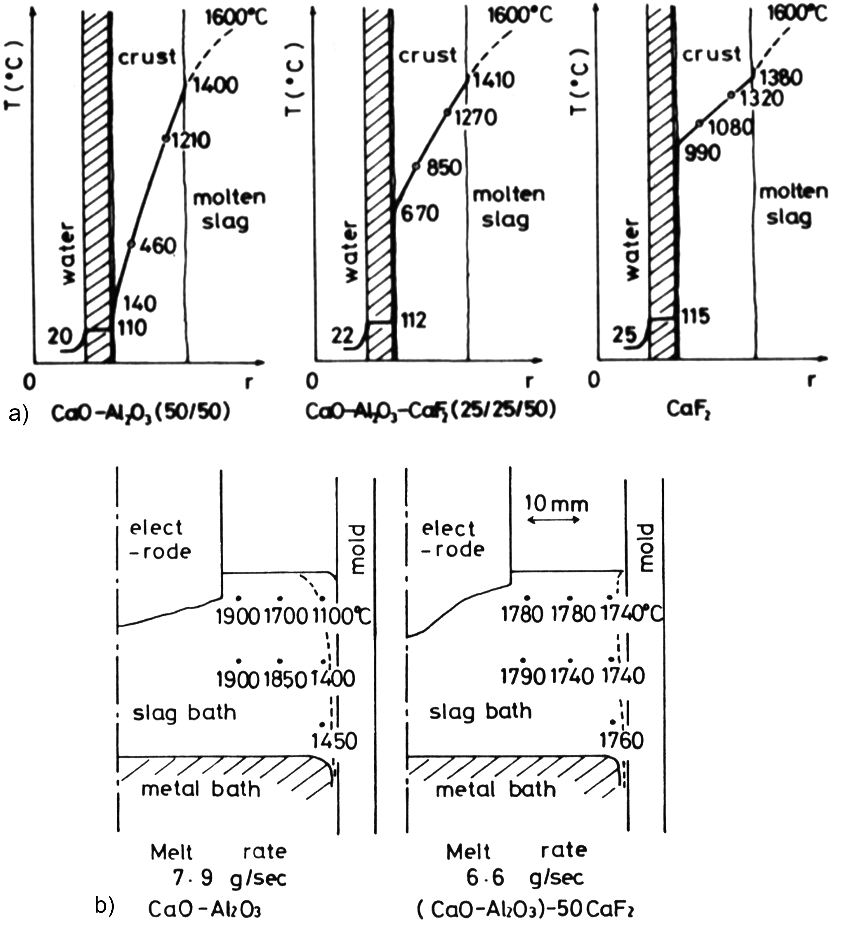
(a) Computed temperature profiles in the slag skin region for levels of mould current depending on the slag composition, Kusamichi. 28 (b) Computed temperature profiles (using experimentally determined slag-mould heat transfer coefficients) in the slag bath using two different slag compositions, Kusamichi. 28
The experimental determinations of the mould current on laboratory furnaces show that it may vary between zero and 80% of the total process current depending on the slag composition and process operating parameters.10,27,28,31
Although there have been no direct measurements of mould current in industrial operations, its presence has been inferred in industrial furnaces from several aspects of the operation. It has been observed that when the mould is fully isolated electrically from the active circuit, the ingot surface deteriorates when compared to the ingot made in a fully connected mould (Figures 4(a) & (b)). The condition of the ‘insulated mould’ ingot surface corresponds to the situation prevailing when the peripheral region of the slag and the ingot pool surface is too cold. The lack of mould current causes a concentration of energy in the centre of the slag as opposed to a finite mould current which causes heating of the peripheral regions. The experimental data of Kusamichi 28 shows that the principal effect of mould current is to change the slag temperature profile so that the peripheral regions are hotter, as shown in Figure 3(b).
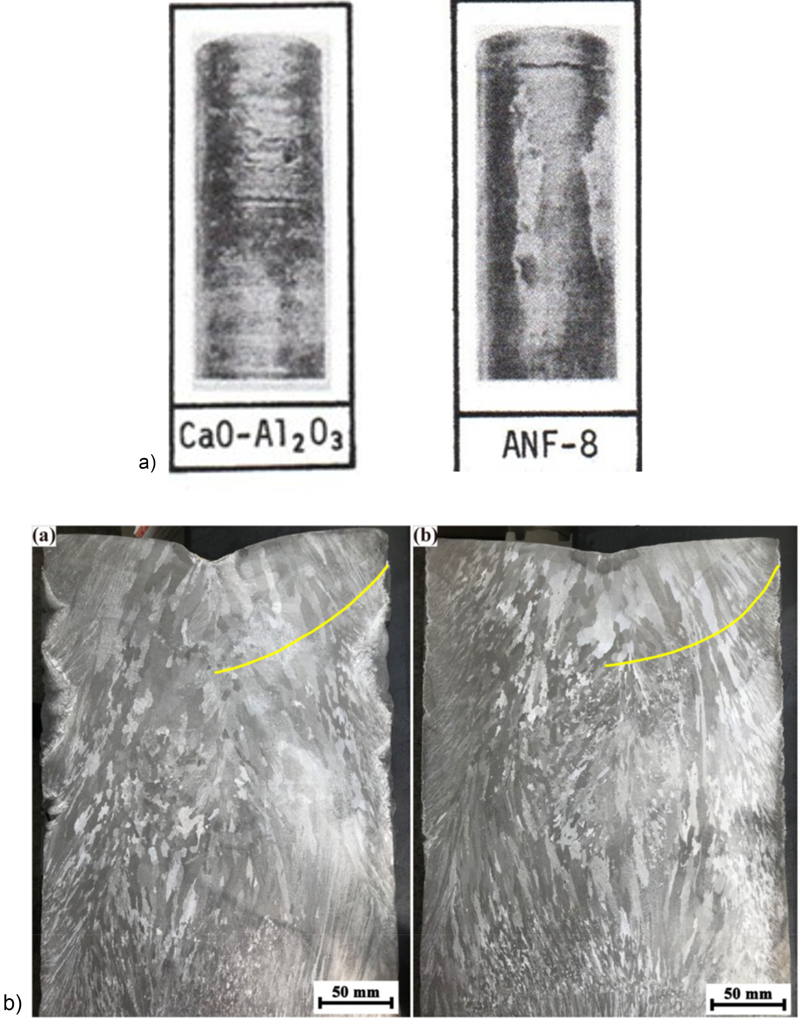
(a) Surface quality obtained with the same melting rate and two different slag compositions, low alloy steel, 80 mm diameter. Kusamichi. 27 “ANF-8” composition is 60% CaF2 + 20% Al2O3 + 20%CaO; “CaO-Al2O3” is 50% CaO + 50% Al2O3. (b) ESR ingots of IN718 melted using the same conditions. Ingot (a) with insulated mould, ingot (b) with the mould electrically connected to the baseplate, Liu. 32
The data presented by Kusamichi 27 also demonstrates that the change in peripheral temperature due to the CaF2 content causes an increase in ingot surface quality even when the two slags (with/without CaF2) are melted at the same rate and with similar slag skin thicknesses (Figure 4).
Yang 33 demonstrates the effect of mould current on the surface quality feature with tests on a pilot-scale ESR furnace producing ingots of an alloy steel. The report attributes surface changes to a mechanism causing slag temperature changes which result from variations in the total slag volume although that change would also vary the mould current component. It is to be noted that melting with a large slag volume, a condition where the mould current would have been zero due to a very thick slag skin, also produced arcing from the ingot to the mould.
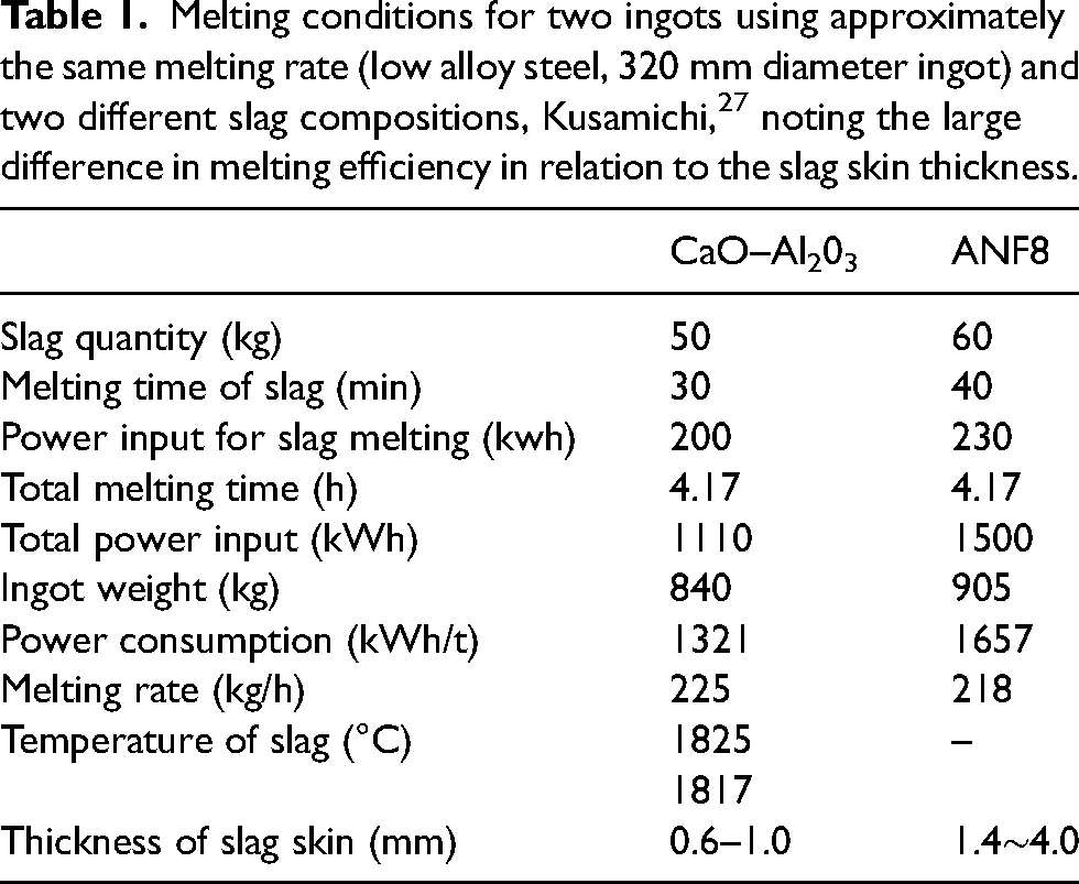
One result of the above mechanisms is the commonly observed process characteristic that ‘good’ ingot surface is generally associated with a less efficient power consumption, measured in kWh/Kg (Table 1,
23
Melting conditions for two ingots using approximately the same melting rate (low alloy steel, 320 mm diameter ingot) and two different slag compositions, Kusamichi, 27 noting the large difference in melting efficiency in relation to the slag skin thickness.
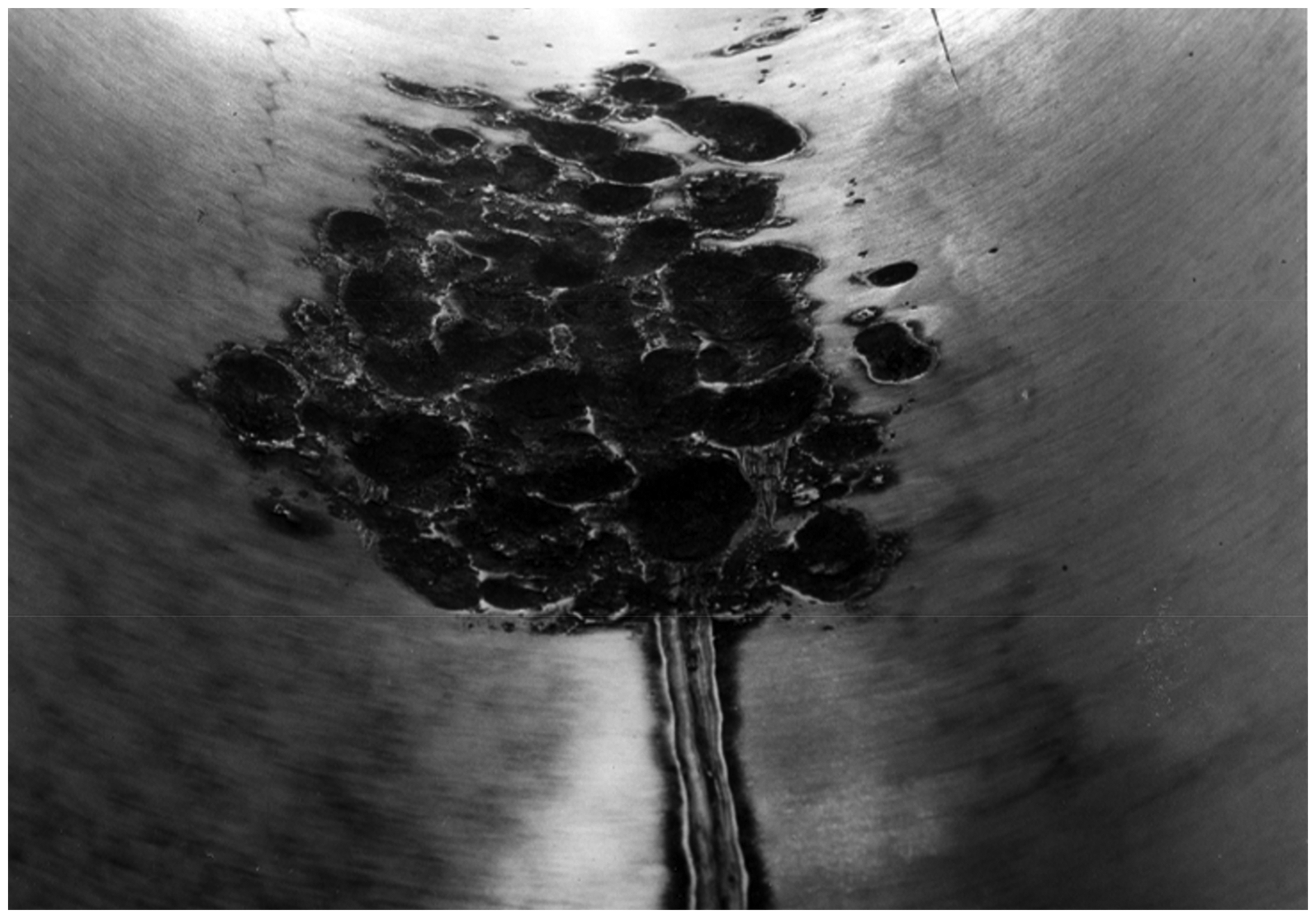
During industrial melting, the influence of mould current interruption can occasionally be observed as an intermittent feature. The event occurs in melting at a low melting rate when the slag composition used leads to a slag pool temperature profile close to the slag liquidus temperature. The mould current interruption occurs when a transient variation in the operating parameters produces a change in the slag temperature distribution. The change lowers the temperature of the slag peripheral regions so temporarily making a substantially thicker slag skin in the slag/mould contact region. The condition consequently changes the mould current from finite to zero. An example of such a change would be small variation in electrode immersion which causes the slag skin region to sufficiently cool that it can temporarily prevent the flow of mould current. The furnace control systems normally correct the condition over a subsequent time. The resulting effect on the ingot is an abrupt deterioration in the surface quality and a change in the liquidus isotherm shape which may produce solidification defects such as tree rings. This ingot appearance has frequently been observed during development of melting practices for alloy ingot practices requiring a low melting rate. Further industrial evidence of mould current may be seen from the development of the ‘live mould’ concept of furnace design18,32,34–36 (Figure 5).
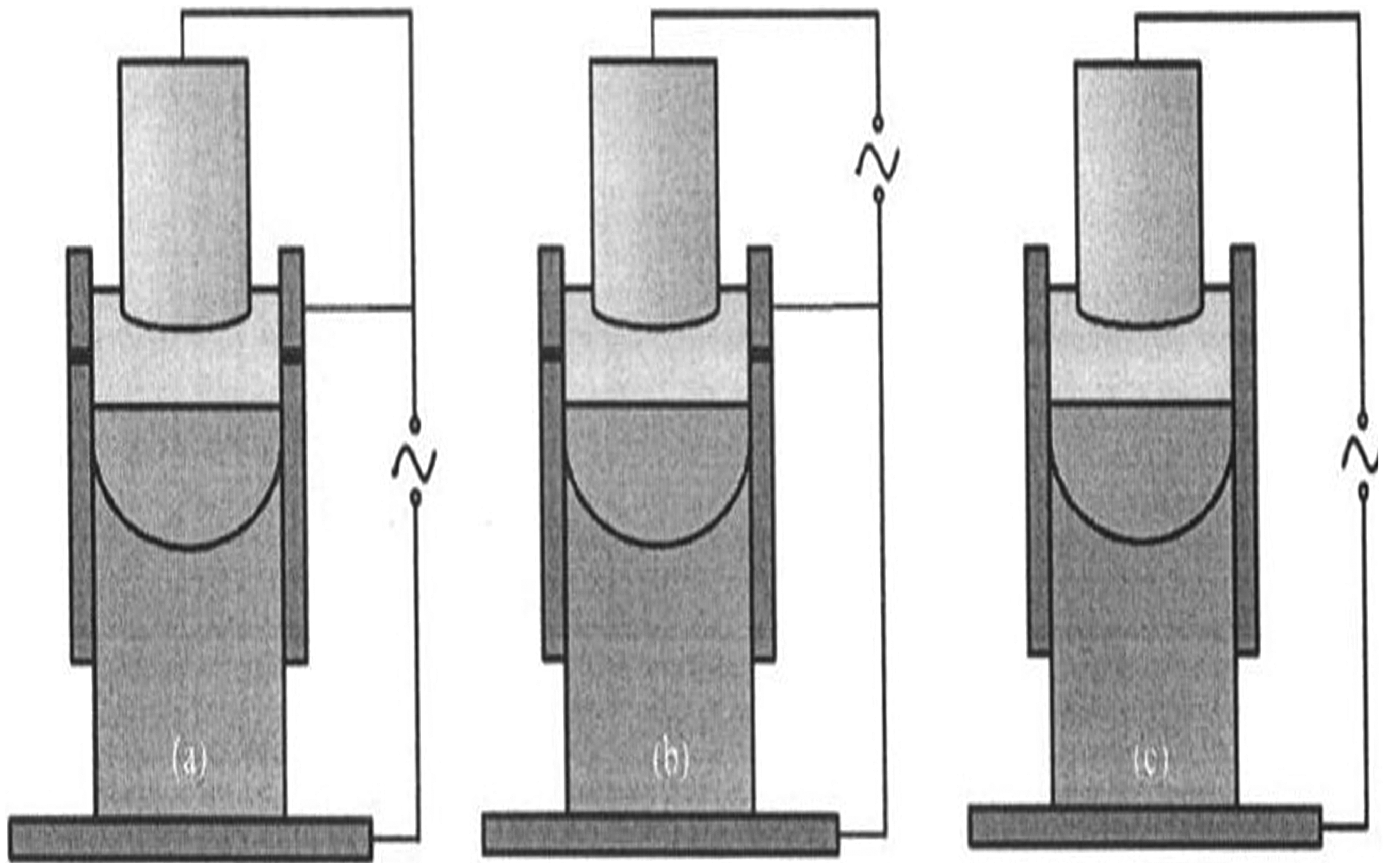
ESR electrical configurations with relative movement between the mould and ingot. (a) Live mould “down,” (b) live mould “up,” (c) conventional connection, Dong. 18
The design intention of this method is that all of the process current should flow into the upper portion of the mould and so modify the slag temperature distribution. The result is that the radial temperature distribution at the ingot pool surface is more uniform and so should produce solidification under a more favourable profile of solidification rates in the ingot. However, results from modelling this proposal18,34 indicate only a marginal change to the ingot solidification rates in comparison to the conventional ESR process with the inclusion of mould current (Figure 6).
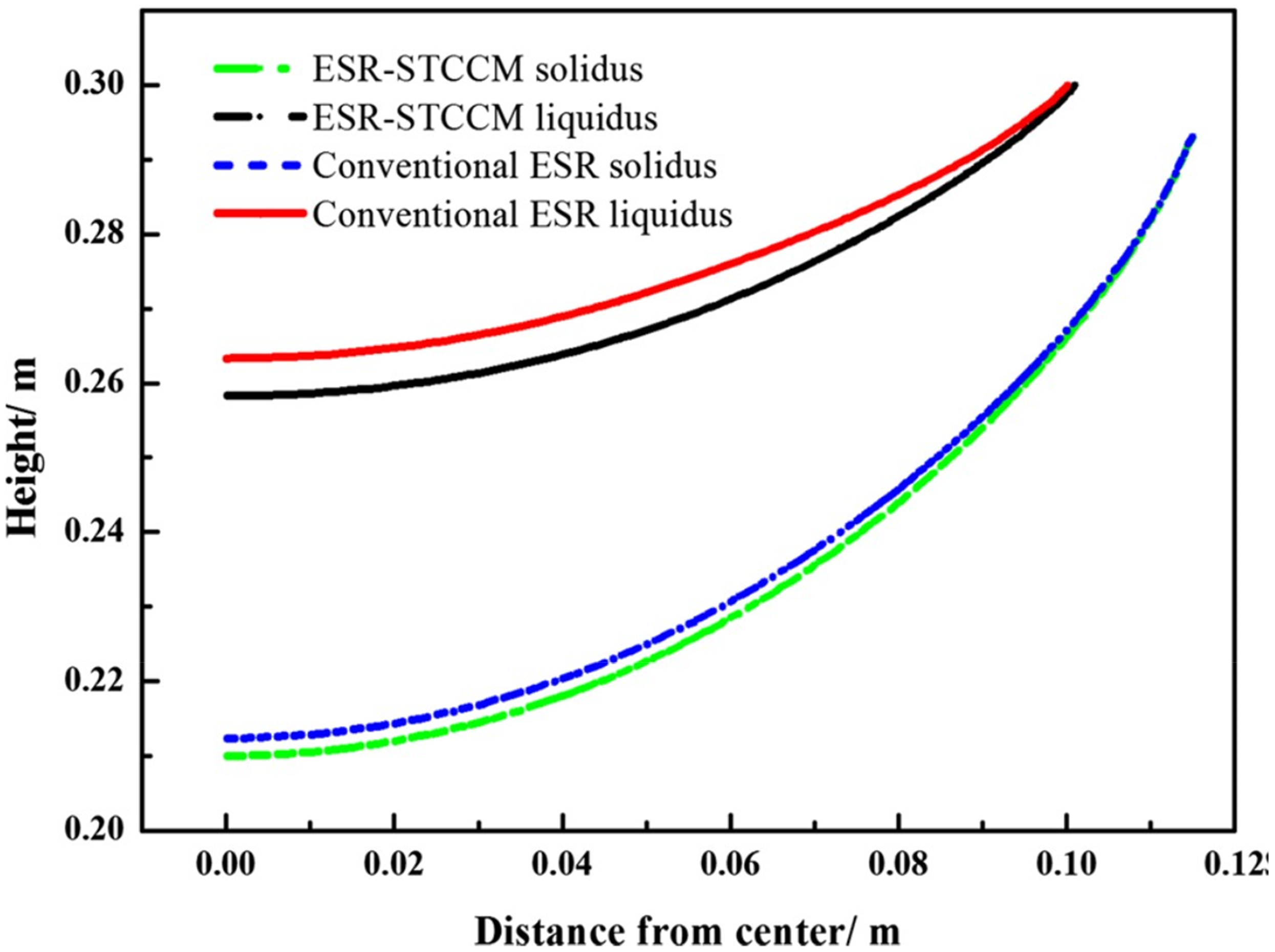
Computed solidification conditions for conventional and live mould (STCCM) configurations, Dong. 34
In contrast, Liu 32 determined the structure of a 200 mm diameter superalloy ingot remelted by ESR under conditions the mould was either insulated or conducting. It was found that the ingot structure was improved by the presence of mould current (Figure 4(b)). The experimental data given in this report indicate that although the liquidus profiles were similar, the secondary dendrite arm spacing in the ingot centre was 25% smaller in the presence of mould current. The ingot surface was also found to be of a higher quality. The above conflicting conclusions on the effects of mould current on ingot structure between insulated and conducting moulds could arise from the difference in the process heat balance of small furnaces as opposed to that of the industrial-scale furnaces in respect of both slag temperature distribution and specific melting rate. 37 Gao, 38 from determinations of slag temperature on an ESR furnace of 360 mm diameter, found that there is a difference in temperature distribution in the slag between the ‘live’ and ‘insulated’ mould configurations. The results show a higher temperature in the peripheral regions of the slag in the case of the ‘live’ mould, as was determined also by Kusamichi. 27
Industrial operation of the live mould design (Figure 5) has shown that the main practical result of the design is that the ingot surface is superior to that obtained in conventional furnaces. Holzgruber 39 compared the metallurgical results of the conventional configuration with that obtained in the live mould concept, reporting that both the surface quality and segregation degree of the ingot were improved in the live mould operation. However, the concept is presently only operated in an ingot withdrawal mould which presents difficulties when melting alloys having a large solidification temperature range. 36 In conventionally designed furnaces with movement between the ingot and mould, the alloys with a long solidification range have been found to present issues with repetitive minor ‘runouts’ which cause a deterioration of surface quality. An additional issue in the use of the live mould concept is that the electrical contact is directly between the liquid slag and the mould. The contact is maintained by the use of either graphite or steel inserts which permit good electrical conduction since no solid slag skin is formed. No reports are available relating to the potential contamination of the ingot by slag or metal reaction with this contact material. It is, in principle, possible that a water-cooled copper live mould could be used in the case of a very high-power input and a high CaF2 slag in order to maintain a thin, highly conductive slag skin but no such system has yet been reported.
In respect of the operation of the general process, the above studies indicate that the presence of a substantial mould current permits the formation of a good ingot surface at a low melting rate. This feature presents a potential advantage in the manufacture of high-alloy compositions where a low melting rate is essential to avoid segregation. However, industrial results demonstrate that it is possible to produce high-quality ingots in a conventional furnace when using slags of low CaF2 content where the mould current should be zero. The slags used create a thick, thermally insulating slag skin. The use of a high energy input and high melting rate in such cases permits a liquid head of metal to form in the ingot head, leading to a good surface quality. The alloys manufactured by this practice are generally not segregation-sensitive and the high melting rate is hence not a production issue.
Modelling of mould current flow in electroslag remelting
Current flow in conventionally designed furnaces has been modelled using CFD techniques9–24 largely neglecting the possibility of current flowing through the mould. Kharicha 14 Abdia 22 and Hugo, 12 constructed models in which it was assumed that a mould current component was axially distributed through the slag skin over the entire slag/mould contact region in a pattern following the liquid slag voltage gradients. The Joule resistive heating effect of current flow through the electrical resistance of the slag skin was included in the models. The mould current was modelled in all three cases12,14,22 as a function of an assumed combined resistivity comprised of the slag skin and any contact resistance at the skin/mould interface, represented by a conventional electrical conductivity value. In these models, a mould current large enough to significantly affect the slag temperature distribution was found to require a conductivity of the slag skin contact region of not less than 15 S.m−1.
The model proposed by Kharicha 14 is based on a concept in which the current flows into the mould through the slag skin in the slag region contact and returns to the ingot at the contact between the ingot top surface and the slag skin. The ingot top surface is liquid at this contact point, forming the liquid head of metal in the ingot which produces the good surface normally seen in ESR ingots. The contact, therefore, has a temperature above the liquidus of both the metal and the slag hence causing a thinning of the slag skin by melting it.26,40 The relation between energy dissipation in the slag skin and ingot surface quality is discussed with the conclusion that the proportion of current passing though the mould is directly related to ingot surface quality. A large mould current produces a good surface quality. However, it is proposed that this relationship must allow for the effect that sufficiently high melting rate when used in resistive slags can achieve the same good surface result with no mould current. The good surface quality in that case is due to the operating heat balance which permits a high temperature at the ingot top periphery independent of a mould current presence. The model is constructed for the case where the mould is ‘insulated’ i.e. not connected to the baseplate. If the mould is electrically connected into the circuit by the baseplate contact, the mould presents a lower resistance path than that existing in the path (slag skin and ingot). In that case, most of the current flows through the mould directly to the baseplate and not through the ingot, a situation analogous to the VAR mechanism for current flow experimentally verified by Shevchenko. 30
Patel 15 modelled the effect of mould current on the ingot temperature distribution by assuming that 25% of the process current flowed into the mould in the slag/mould contact area within 10% of the slag/air surface. The required electrical conductivity of this contact was not computed. However, if a slag skin of 2 mm thickness and a slag skin/mould contact with zero resistance is assumed, the data given leads to a value of 44 S.m−1 for the required electrical conductivity of the contact region necessary to fit the melting conditions of the model.
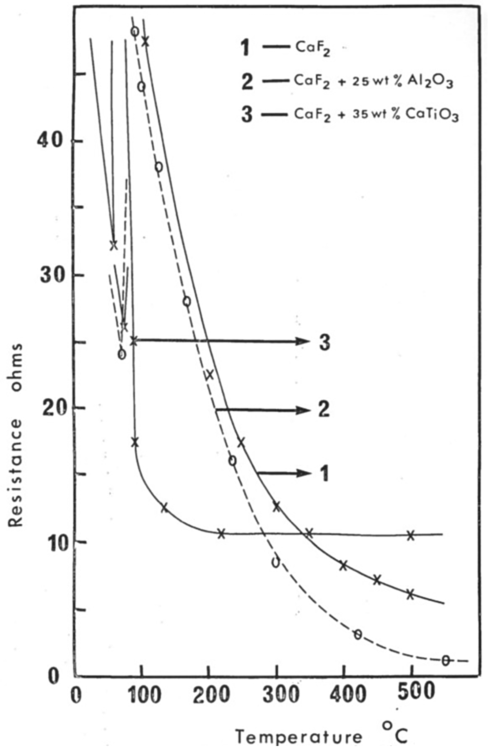
The model of mould current developed by Kharicha 9 is based on the concept that the liquid slag/mould interface is a perfect electrical conductor. On that basis, using the concept of a heat balance based on experimental ESR melting, the resulting temperature gradient is used to determine the slag skin thickness and electrical conductivity profile. The results obtained in this model are compared with experimental values of the total power required for the ESR melt and indicate that the solid slag skin must have a high temperature throughout its thickness if it is to constitute the total resistance to current flow for the contact region. The model of Kharicha 14 examines this aspect of the mould current flow in more detail. In this work, model results suggest a range of 0.2 to 1 S.m−1 for the conductivity of the (slag skin + slag/mould) contact from a comparison of the model results with estimated mould currents found in practice. The model developed by Yu 11 assumes a slag skin conductivity of 4 S.m−1. The conditions used by Kusamichi 28 would have resulted in a slag skin thickness of 1–2 mm, although the experimental values are not reported. On that basis, the experimentally determined value of mould current (for a slag containing 50% CaF2) leads to a slag skin conductivity of 6 S.m−1. The only reported experimental values of the (slag skin + contact) region are from Joshi25,31 who, using a resistance network analogue, experimentally determined a slag skin resistance of between 5 and 20 S.m−1from results obtained on a laboratory-scale DC ESR furnace. This range of values agrees with the further results of Joshi, 25 Figure 7) if the mould contact area has an average temperature of 200 – 300C. This finding is reasonably consistent with thermal conductivity calculations made using reported temperature measurements of the mould. 31
The above values of the overall contact area conductivity are much higher than the values expected from the very low conductivities of the solid fluoride and oxide phases. They are to be compared with the conductivities of the ESR liquid slags which are in the region of 300–600 S.m-141,42 which decreases by several orders of magnitude for the equivalent solid phases in the temperature range of 100–400C.
Conduction and slag skin structure
Medovar 10 and Kusamichi27,28 both indicate that the electrical and thermal conductivities of the slag skin both depend on the composition of the slag. The main feature in both studies is that the slag skins in slags with high CaF2 content have higher values of these properties than do slags which consist principally of oxides. Kusamichi 28 found experimentally that the mould current was zero when operating with a (CaO + Al2O3) slag containing no CaF2 ; near-zero when operating with a slag composition of (CaO + Al2O3) + 25%CaF2 but high when operating with a slag having 75% CaF2. This result corresponds to the expected variation in the conductivity relationships of the slag skins formed. The modelling work reviewed above contains the assumption that the electrical resistance of the overall contact region of the slag can be represented by using a lumped ‘conductivity’ for the combination of the slag skin thickness and the contact between the slag skin and the mould wall. The assumed conductivity would then contain the effect of the slag skin composition and the slag temperature distribution. Kusamichi27,28 demonstrates the large difference in slag temperature distribution between the all-oxide slag and one with a high CaF2 concentration (Figure 3(b)). The difference is attributed to the magnitude of the mould current resulting from the composition dependence of the thermal and electrical conductivities of the contact region although a part of the difference in slag bulk temperature would have resulted from the difference in slag skin thickness between the processes.
There are no reports of the magnitude of mould current in industrial operations. Temperatures in the slag region of industrial furnaces are lower overall than in the smaller laboratory furnaces used for experimentation on mould current 37 which results in thicker slag skins in industrial furnaces than those in the smaller furnaces. Industrial ESR processes generally have slag skins of thickness in range 4–7 mm whilst those in laboratory furnaces are generally in the range of 1 −2 mm in thickness. Using a single value of conductivity based only on the slag thickness to represent the overall contact resistance of the slag skin and mould contact region, however, neglects the additional influences of the temperature differences as a function of furnace size. The skin-to-mould contact resistance is not a direct function of slag skin conductivity. It depends also on the physical properties of the contact such as contact pressure, slag skin plasticity and the temperatures of the two contacting surfaces.
The models considered above assume either a given constant slag skin thickness and or a singular one derived from a heat balance based on a given thermal and electrical conductivity. Kharicha 14 assumes a constant slag skin thickness of 1 mm. The model used by Hugo 12 demonstrates the effect on mould current of slag skin thickness over the range 1 to 6 mm, assuming a constant slag skin electrical conductivity of 15 S.m−1. The results of this model indicate that as the slag skin thickness is increased there is a significant change in the heat distribution in the bulk slag but that there is still a significant mould current when the slag skin thickness is increased to 6 mm.
The above reports do not, however, examine why the overall conductivity of the slag skin/mould contact region is a function of bulk slag composition. The experimental work of Joshi25,31 demonstrates the effect of slag composition on the apparent conductivity of the contact region showing that although the principal dependence is on mould face temperature it is also a function of slag composition. Kusamichi27,28 found that the composition of the slag had a strong effect on the thermal conductivity of the slag skin. This aspect has also been extensively investigated for similar slag skins formed during the conventional continuous casting of steel. 43 The experimental studies indicate that the combination of thermal27,28 and electrical properties of the slag skin, together with the effect of bulk slag temperature, determine the skin thickness. The combined effect has been modelled by Yanke 44 confirming that the magnitude of the mould current should be a function of bulk slag composition. The use of a slag of low CaF2 content gives higher bulk slag temperatures27,28 but since the thicker slag skin which it forms has a low electrical/thermal conductivity the resulting mould current is low. A practical result of the above studies is a possible explanation of why the ESR melting of high-alloy compositions such as superalloys has developed into techniques which use slags with a high CaF2 content. The slags have liquidus temperatures and other physical properties which do not appear to be uniquely optimum slag compositions for that purpose, but the compositions are found to be necessary for optimum production results.
The phase composition of slag skins in both ESR and in conventional continuous casting of steels has been examined43,45 and found to be a highly complex mixture of transparent crystalline phases and fine-grained, opaque phases. Heat transfer determinations 21 on the slag skin in continuous casting practice have indicated that the transparency of the crystalline phase leads to a high value of thermal conductivity. Typical ESR slag skins40,46,47 consist of CaF2 crystalline regions together with fine-grained volumes of complex solid oxides with proportions which relate to the composition of the slag. The formation of similar structures in continuous casting slags has been studied 48 in relation to minor amounts of SiO2 and TiO2. These oxides were found to change the morphology of the CaF2 phase. 49 The same compositions are commonly found in industrial ESR slag compositions which suggest that the minor additions of these oxides together with MgO may play an important role in determining the mould current. Crystalline CaF2 is highly transparent 50 leading to a high radiation conductivity. It also has a higher electrical conductivity51,52 than the oxide solids used in the slag compositions. The above studies indicate that the CaF2 content is the determining slag component in respect of establishing the magnitude of the mould current in ESR.
The electrical conductivity of the solid slag skin compounds in all cases is a strong function of temperature. If there is a high thermal resistance at the slag skin/mould wall interface it is reasonable to assume that the slag skin would have a high temperature throughout its thickness and so would have a low overall electrical resistance. If there is a low thermal resistance, the section of the slag skin close to the mould wall would have a low temperature and so would represent a high electrical resistance. Hence, mould current is not only a function of the bulk slag composition but also of the temperature of the mould inner face and the contact thermal resistance between it and the slag skin.
The contact region
An as-yet undetermined feature of the mould current is the manner in which a high current density can be carried at the slag skin/mould contact. The operation of the ESR process in direct current, 50/60 Hz alternating current mode or low-frequency current mode have all been shown to involve Faradaic reactions at the slag/metal interfaces which contribute to the composition changes experienced between the electrode and the ingot.53–57 Since the mould is metallic copper and the liquid and solid slag compositions are ionic conductors, the current passing through the contact between the mould and the slag skin should also do so through a Faradaic reaction. However, no evidence of a Faradaic process at the slag/mould interface has been observed or reported in any experimental studies or in any industrial experience.
It is possible that at the high temperatures calculated from the experimental measurements of Kusamichi27,28 for slag skins containing CaF2, there is sufficient ionic mobility in the fluoride solid phase to permit interface conduction in a process similar to that observed in studies on double-layer capacitance effects in electrolytic processes and semiconductors.58,59 In this case, the slag skin/mould contact electrical resistance would be a function of both temperature and slag composition, particularly with respect to the CaF2 content. Maksimovitch 16 comments that when using a steel mould and 50 Hz power, the mould current is partially rectified in a mode which produces a small positive bias at the electrode/slag interface. This effect would only be detectable in an ESR system powered by a simple voltage-tapped transformer as was the case with early furnaces in the former USSR. In modern furnaces with saturable-reactor control or inverter systems, the effect would be reduced by the electrical design. It would also be undetectable within the distorted waveforms produced by that form of power supply. The rectification effect was attributed to the presence of continuous small arc discharges at the contact interface in combination with the higher temperature of the working face of the steel moulds.
The extent of inter-surface contact between the slag skin and the mould wall is also a function of composition. A study of the physical properties and structure of the slag skin developed by mould casting flux in the continuous casting of steel45,60,61 determined that when one of the solid phases was a glass, the skin had a small level of plasticity. This feature allowed a smooth close contact with the mould. In consequence, the heat flow is observed to increase. Similar studies on the equivalent slag skin in ESR62–64 report the presence of a thin glass-like layer on the slag skin/mould contact surface in compositions containing SiO2. This feature is used in the formulation of ESR slag compositions used when there is relative movement between the melt region and the mould although the form of this movement differs from that in continuous casting. It is possible that a skin composition with a large liquid/solid temperature interval could achieve the same effective plasticity, so influencing the contact electrical resistance by facilitating the double-layer effect.
The apparent conductivity of the contact region is found experimentally10,25 to be very dependent on the presence or absence of TiO2 in the composition. The effect of a TiO2 component in increasing the apparent conductivity of the contact region can be attributed to the presence of the Ti3+/Ti4 + ion couple65,66 which not only imparts partial electronic conductivity to the liquid slag but also introduces the possibility of direct electron transfer from the slag skin to the mould.
An alternative approach is to consider that the slag skin could contact the mould wall through a series of minor small arcs as suggested by Maksimovitch. 16 Small points of light around the top surface of the slag/mould contact accompanied by a ‘buzzing’ sound have occasionally been reported from industrial users. As the liquid slag progressively rises in the mould during melting, it momentarily contacts the mould wall before it forms the solid skin. Small arcs may form at the contact points during this process and provide the conductive path. The model proposed by Patel 15 contains the assumption that the mould current is carried by a small segment of the slag skin close to the top surface of the slag volume, an assumption which is related to this effect. In contrast, the models of Hugo 12 and Kharicha 14 assume that the mould current is carried by the slag skin over the full depth of the liquid slag. The axial distribution of the current over the slag/mould contact region has not been measured experimentally leaving the potential for this alternative mechanism undetermined.
In summary, the mould current present in small furnaces has been studied and the process parameters which affect its magnitude have been investigated. However, there is no direct experimental evidence of the mould current magnitude in industrial operations, or of its influence on the structure of the ingot produced in the large-scale process. Industrial practice now accommodates the presence of mould current in that whilst early versions of the process used a system in which the mould was electrically insulated from the baseplate (Figure 8(a)).
(a) Early ESR assembly method, Hoyle. 26 Note the electrically insulating insert between the mould and baseplate. (b) Modern ESR assembly practice, Consarc Corp. Note the positive electrical connection between the mould and the baseplate.
Modern furnace practice requires careful attention to ensuring an excellent electrical contact between the mould and baseplate (Figure 9(b)).
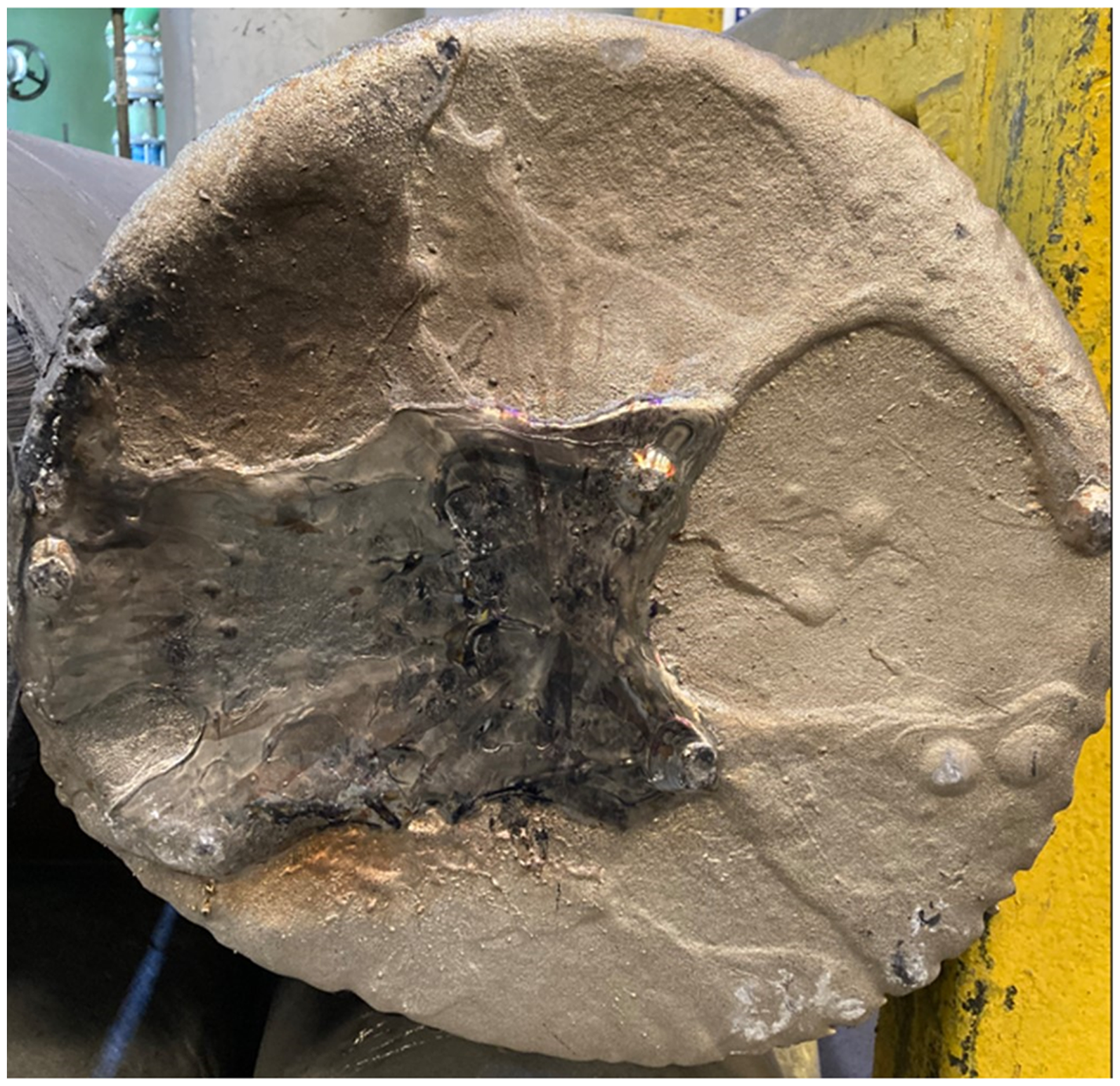
VAR mould interior damaged by repeated “shorting” arc events.
Mould current, however, is unlikely to be present in all melting practices. Small-scale experimental studies indicate that melting through slags with a low or zero CaF2 content takes place with no mould current but high-quality ingots can nonetheless be industrially produced with such slags. However, the processes used in that method involve relatively high melting rates. 23 Such conditions evidently provide a peripheral temperature at the slag/ingot pool interface sufficient to permit the liquid metal head which is required for high surface quality, to form at the top of the ingot. 26 The heat balance is established in spite of the absence of a mould current. Using slags with a high CaF2 content increases the mould current thus enabling the temperature distribution required for good surface quality when melting with low energy input. This aspect may be a critical factor in the production of highly segregation-sensitive alloys at low melting rates
Mould current in the vacuum arc remelting process
Practical experience
A mould current path in VAR, often described as ‘shorting’, has been an intermittent issue in industrial processes for many years. It is the result of a change of the total primary current flow from the normal ingot/electrode direction to a direction from the mould region above the melting zone towards the electrode. It results in serious damage to the water-cooled copper mould as shown in Figure 9.
This situation arises when the electrode comes into close proximity of the mould due to either misalignment or electrode cracking. The heat extraction is unable to accommodate the intense local heating and the mould inner surface is then seriously eroded. In an extreme case, mould puncture can occur leading to a water or hydrogen explosion. The effect is rare in most remelting operations with the notable exception of titanium and zirconium melting. 67 The high current densities required in the reactive metal VAR case when combined with electrode structures which are often irregular and fragile can readily provoke the ‘shorting’ event. The reactive metal remelting furnace control systems are constructed and operated so as to avoid this condition 68 and generally include a component intended to detect the issue and permit an immediate correction. This aspect of the VAR process operations is considered to be a transient instability and is not a component of the normal process. It is not included in the present analysis.
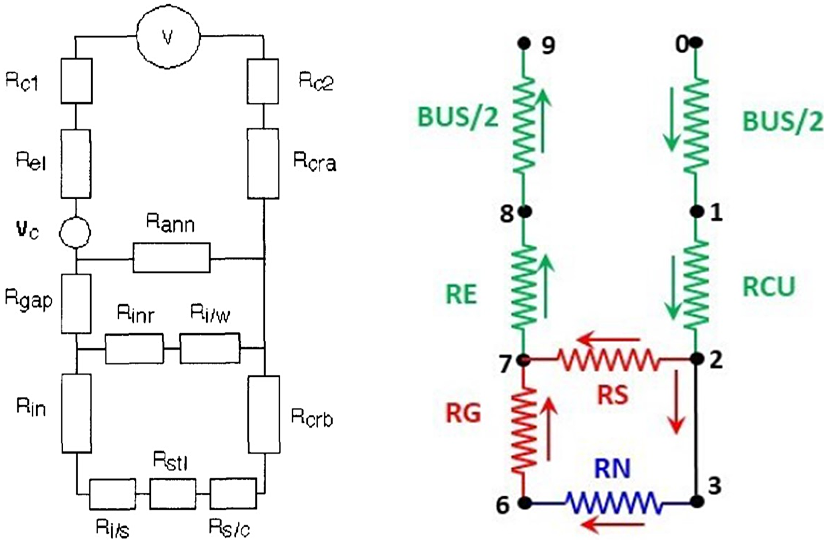
Current flow in the VAR mould flows through three resistance paths:
Path #1; Mould to ingot in the region of the ingot head where there is close contact between the ingot and the mould Path #2; Mould to electrode through the region of the process where the mould is in contact with the crown Path #3; Mould to electrode through plasma contacts across the free space between the electrode and mould surface
These three paths comprise almost all of the current path during steady state melting since the proportion of current passing directly from the baseplate to the ingot is small in that stage of the melt. 69 The experimental measurements of Shevchenko 30 demonstrated this current division through the system but could not quantitatively define the relative proportions.
Mould current flow in paths # 2 and #3 can be observed in the arc behaviour during the industrial process. The arc consists of cathode spots on the electrode, diffuse anode contact and arc plasma which consists primarily of charged species of the more volatile elements of the alloy being processed.70,71 The arc region has been extensively studied at the industrial scale with video observation during the process.72,73 Several effects were noted which relate to current flow between the mould above the ingot pool and the electrode. First, the plasma is not fully confined to the region between the electrode melting face and the ingot pool surface. A portion of the plasma intermittently migrates to the electrode/mould gap as cathode spots move to the side surface of the electrode (Figure 10).
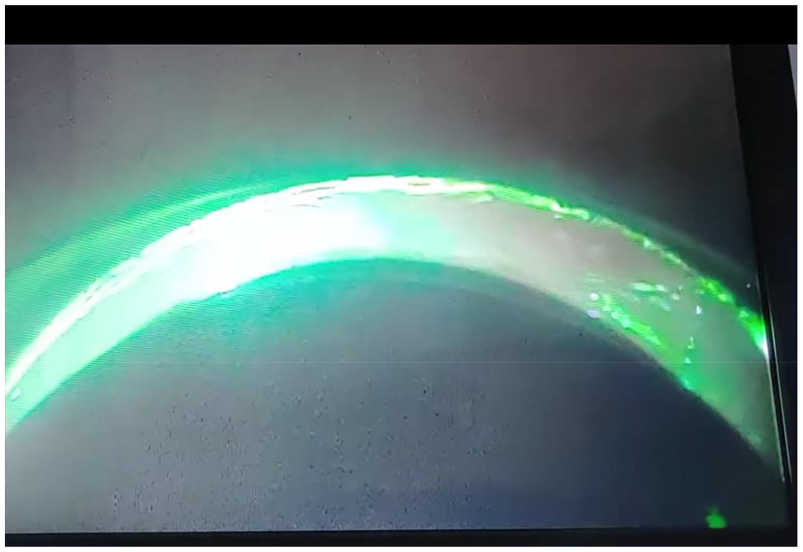
Arc plasma localised into one radial position. 650 mm dia VAR, low alloy steel.
Second, whilst plasma and cathode spots are in this position, there is considerable transient heating of the ‘crown’ region of the ingot surface and crown detachment can be seen when this effect is taking place (Figure 11).
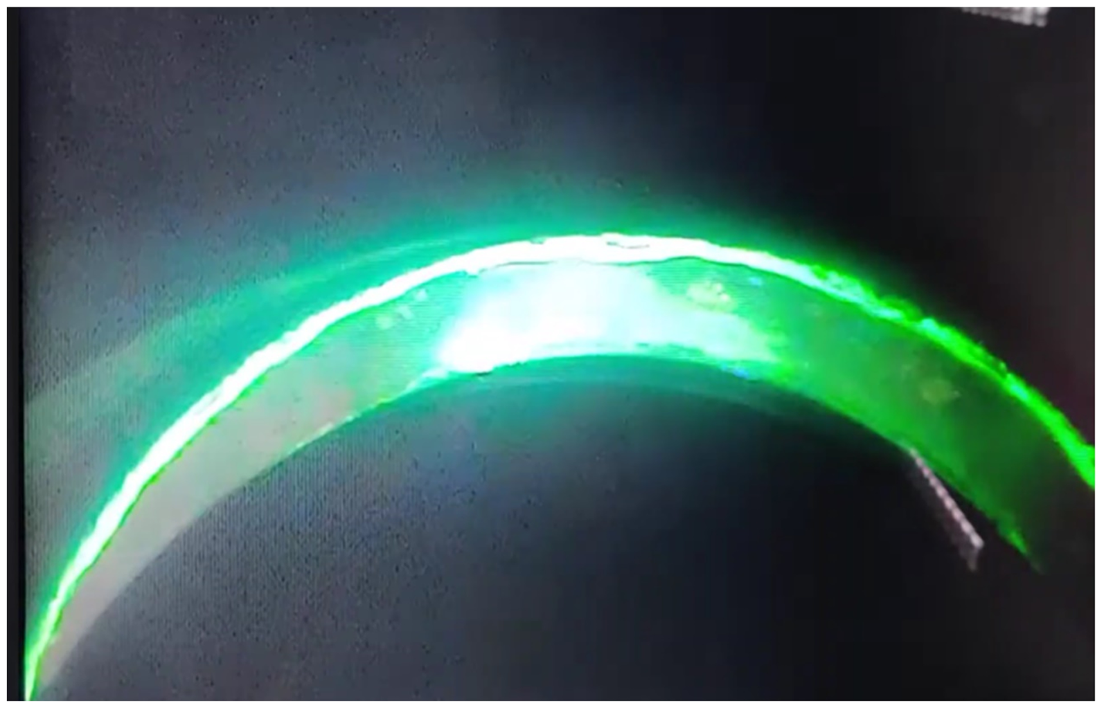
Localised arc plasma causing crown fall-in. 650 mm dia VAR, low alloy steel.
The extent to which these effects occur appears to be qualitatively related to the ‘arc gap’, i.e. the separation between the electrode melting face and the ingot pool surface. 74 The density and half-life of the plasma before it is discharged relates to its composition. The composition can be significantly affected by any gas present, either added to the process as a pressure control, or evolved from the melt region. It is also influenced by helium leaking from additions made to the mould/ingot contraction gap to modify the ingot/mould heat transfer.73,75 The amount and stability of the plasma cloud affects the amount and ratio of current transferred from the mould to the electrode through paths #2 and #3. If the gas content of the local volume allows the plasma to become sufficiently dense and mobile, it can create a significant mould current through path #3 and ultimately develop into a stable gas discharge known as ‘glow’ in the VAR process. This condition occurs when there is substantial gas evolution from the alloy being melted by reaction, degassing or evaporation. It is common, for example, in steels with a high manganese content. The discharge is self-sustaining. The generally applied method to correct the issue is to momentarily discontinue the power. The process interruption caused by glow has the potential to create tree ring defects in the ingot 76 since both the condition and the corrective actions substantially change the melt rate and the heat balance of the solidifying region.
Mould current has been measured at the industrial scale29,30,69,77,78 by determining the voltage drop along the mould. In contrast to the ESR system, since the VAR power system uses direct current, the small voltages occurring along the mould axis can be measured with a high degree of accuracy free from induced voltage interference. Shevchenko, 30 on the basis of measurements made during the melting of a 440 mm VAR ingot of alloy IN718, diameter estimates that between 35 and 65% of the total process current passes directly from the mould to the electrode (paths #2 and #3) with the remainder passing through the ingot pool surface (path #1). Similar reported estimations and measurements of the current in paths #2 and #3 vary greatly, indicated by Risacher 78 to cover a range from 5% to 50% of the total process current. The reasons for the variation in estimations and experimental results are not presently understood but are probably linked to variations in the process parameters, particularly to the arc gap dimensions.
Models of the vacuum arc remelting process and mould current representation
A number of VAR models predicting ingot structures have used the concept that the process current in the VAR process is carried almost entirely by the mould in the region below the ingot pool surface1,74,79 with no allowance for mould current. The resulting process predictions have largely been verified by comparison with industrial experimentation. However, the assumed input parameters were not tested in those models by computation of the melting rate from the given values of input power. This latter test reveals the necessity for modifying the energy input assumed to control the ingot pool surface temperature in order to allow for the power dissipation in paths #2 and #3. The inclusion of mould current in models of the VAR process used in recent reports was prompted by the finding that assuming the input power was comprised entirely by path #1 led to a melt rate which was considerably higher than that found in practice.
Recent models of the VAR process have included a form of ‘efficiency factor’. It is an assumed constant intended to reflect the proportion of the total current which is applied as heat energy to the ingot pool surface, i.e. the current in path #1. In models, this factor has been set at a values of between 3 and 90%.19,20,22,24,80 The input parameters of the commercial software ‘MeltflowVAR’, 81 for example, contain a user-specified condition (‘Cb’) which represents the fraction of current carried by paths #1. The default value in this case is 0.7, corresponding to the experimental result given by Shevchenko. 30 The models proposed by Eickhoff, 82 Karimi, 83 Pericleous 84 and Abdia 22 also all require an assumption of this proportion of the total process current. Eickhoff 82 uses a model in which the current in paths #2 and #3 is assumed to be 3% of the total power. Williamson 80 assumes a melting efficiency of 0.478. Karimi 83 modelled the effect on ingot solidification of paths #2 and #3 current variations between 30 and 70% of the total process current. Pericleous 84 assumed that this current equalled 45% of the total current. Patel 85 estimates that sum of path#2 and #3 current is between 25 and 50% of the applied current from experimental and modelling studies carried out on 550 mm diameter ingots of IN718. The ‘efficiency factor’ applied to the models is, therefore, an experimentally established constant. In practice, it will be a function of the applied process parameters, for example, electrode/ingot diameter, alloy and voltage.
The models in general assume that the ingot is in good electrical contact with the mould for an assigned small distance below the pool surface (path #1). The model described by Shevchenko 30 for example sets this distance at 0.02 m in a mould of diameter 0.50 m. This contact distance would also represent the main path for current to flow into the ingot from the mould, making the equivalent circuit one of two resistances in parallel, one representing the sum of paths #2 and #3 and one representing the sum of all three paths. This scheme is equivalent to the one used Joshi25,31 to represent the equivalent circuit of the current paths in ESR and by Ballantyne 13 to represent ESR and VAR circuits.
A similar resistance network scheme was also used by Williamson (Figure 12, 29 ) to describe experimental results obtained from the VAR processing of a 500 mm diameter ingot of IN718.
All industrial VAR processes all operate with the ingot/mould combination as the negative (ground) pole of the circuit. The relative magnitude of these resistances is different in a system where the ingot/mould combination is the positive (ground) pole due to the consequent changes in arc behaviour. 86 The influence of the resulting change in current distribution between the three paths arising from that change in polarity adversely affects the ingot heat balance, the solidification behaviour of the ingot and the melting efficiency. 87
The parallel resistance concept may be considered in relation to the arc behaviour. The arc mode used for the remelting of steels and superalloys is the ‘diffuse’ arc, consisting of many mobile transient cathode spots generating a plasma.70,71,88 The arc gap in this case is small, in the range of 6–8 mm. The relative values of the path resistances in the parallel circuit lead to the observed current distribution. If the arc gap is increased, the arc may transfer to the ‘constricted’ mode87,89 in which the cathode spots are less mobile and the plasma forms a more structured column. Since the arc resistance component then constitutes a larger fraction of the parallel resistance circuit, the current in paths #2 and #3 increases as a fraction of the total process current. In an extreme case, the effect can be seen as transient melting on the electrode axial surface (Figure 13) during a period in where the electrode/ingot gap is much larger than in normal melting. This condition can be identified by irregular electrode melting (Figure 14).

Electrode melting region showing melting tracks from cathode spot migration in a large arc gap event during an industrial trial VAR melt.
Electrode melting face showing irregular melting resulting from constricted arc formation during a large arc gap period in a trial VAR melt.
The change in arc gap results in a reduction in the melting energy efficiency. Zanner 90 reports that the experimentally measured electrical efficiency of melting in the case of alloy IN718 is significantly reduced by the introduction of a gas (CO or A) which increases the operating arc length the same voltage and current conditions as in normal melting. Since Jardy 91 reports that the radiation loss from the high temperature region is a small component of the heat balance (15%>) the lower efficiency observed by Zanner can be attributed to an increase in the energy loss due to current in paths #2 and #3. During the VAR processing of titanium alloys, normally carried out at a higher melt rate than steels or superalloys, the arc gap is considerably larger (30–35 mm) than in those alloys and the arc is in the ‘constricted’ mode during the operation. This mode would lead to a higher component of mould current in the total power distribution than is the case for the steels and superalloys. However, measurements similar those in the works of Zanner and Shevchenko have not been made for titanium VAR melting and the potential effect of mould current on melting efficiency has not been determined in that system.
Vacuum arc remelting mould current and ingot structure
There is no reported study of the effects of a planned variation of mould current on ingot structure, with the exception of Williamson
69
who attempted to insulate the mould using a coating of TiO2 paint for the melting of titanium alloy 6/4. The result was inconclusive since the arcing process eroded the coating. However, since ingot structure is closely related to arc behaviour, which in turn controls the division of mould current paths, it is clear that variations in mould current are also closely related to ingot solidification structure. The variations affect ingot solidification through the resulting overall heat balance changes and through the transient effects of arc radial variation in the current-carrying proportions of paths #2 and #3.92,93 There are three main potential relations of mould current variations to ingot structure;
Deviations in the overall thermal balance of the system caused by a change in the proportions of the total current carried by each of the mould current paths and hence in the melting efficiency. Changes in the arc position and movement causing variations in the radial position of the mould current's principal path. Variations in the ingot pool fluid movement associated with the above effects.
The effect of the heat balance variation on ingot solidification can be inferred from the extensive reports of work conducted on VAR processing with changes in the total applied current. Detailed results are given in reports of such ingot structure variations in the case of both steels and superalloys24,85,94,95 although most are framed in terms of melt rate variations rather than changes in applied current. However, these two parameters are closely linked for a given ingot size and alloy. These reports indicate that a change of more than 10% in the power received by the melting region causes a significant change in the solidification structure of the solidifying region. The effect of such a change depends strongly on the alloy composition. In an alloy solidifying as a solid solution (e.g. Ti 6/4 or a simple austenitic steel), the change may not result in a significant quality issue. In more complex alloys (e.g. Ni-base superalloys) the change may be sufficient to provoke a serious change in the formation of precipitation structures which subsequent introduce a quality problem.
Changes in the radial distribution of current between paths #2 and #3 associated with changes in arc behaviour relate to the formation of significant defect structures.20,96 The constricted arc mode localised in one radial sector of the pool surface has been identified as a major cause of freckles in the ingot structure.89,90,96,97 Since that mode concentrates both cathode spots and plasma into radial sector it also will produce a concentration of current into the local portions of path #2. The local crown area would then be partially melted and detached from the mould and fall into the ingot pool. The effect has been visually confirmed in several industrial VAR operations, 98 Figure 11) although the corresponding mould current distribution has not been experimentally measured. This sequence of events is held to be a potential cause of the ‘white spot’ defect in superalloy production.98–103
Future directions
Several paths for potential quality improvements in both processes arise from a consideration of the mould current effects. Stabilisation, monitoring and control of the mould current would substantially improve the ingot quality in both processes, assisting particularly in eliminating the occurrence of random, unpredictable defects.
Indirect control of the mould current in ESR appears feasible through manipulations of both the slag composition and the mould working face temperature. The CaF2 content of the slag is evidently critical in establishing a mould current and maximising this content would assist in not only maintaining a good ingot surface quality at the low melting rates required for segregation-sensitive alloys but also in generally improving surface quality in all compositions. Increasing the face temperature of the mould would increase the mould current and have the same effect. Mould face temperature control could be achieved through the use of liquid metal cooling. This method been industrially practiced in titanium processing, but the alternative method of developing a water-cooled mould with lower thermal conductivity would be more attractive for general industrial use. A mould with a surface temperature at a high controlled value would then mimic the ‘live mould’ technique but with the advantage of a static ingot system for the processing of alloys with a high segregation sensitivity.
In VAR, magnitude of the current and its axial variation play a part in the formation and removal of the crown and shelf region of the process. It, therefore, represents an important variable in the procedure. External modification of the mould current proportion of the applied power is possible in VAR. It has been found from titanium processing that the method of coating the mould with a non-conducting paint, usually TiO2, increases the melting efficiency by reducing the mould current. Extension of this method to more permanent coatings could provide a means of stabilising the effect and optimising the consequent influence on ingot structures, most importantly in respect of defects arising from the crown/shelf region. External modification of the mould current is, in principle, also possible through the application of magnetic fields. These techniques may provide the necessary control mode for the manipulation of the mould current both spatially and in magnitude. 92
It is clear that the present melting procedures for both processes permit a random variation of mould current. This variation, therefore, presents an uncontrolled parameter in a process with a specified control scheme. As a result, quality assurance requirements and ‘fixed practices’ should include a technique for the measurement and reporting of mould current.
Conclusions
From the above review, it can be seen that the mould current in both processes is the result of the applied parameters rather than being a primary parameter which can be varied independently. The degree to which a mould current is established during the melting process has a strong influence on the behaviour of the peripheral regions of the ingot formation. It can also be a component of the sequence which results in the formation of defect structures in the ingot.
The magnitude of the mould current in ESR is related to the composition of the slag used. In VAR it is related to the system geometry, primarily to arc gap dimensions. In both processes, its measurement would be an indicator of the system stability and of correct operation following the preset melting parameters.
There is a relationship between the magnitude of mould current and the solidification structure of the ingot in both ESR and VAR.
There are few experimental measurements of mould current on industrial-scale ESR furnace operations. The validity of extrapolation from small-scale experimental ESR furnaces is not at present established. Mould current has been measured on industrial VAR furnaces but the relation of its magnitude to process parameters is not well established.
The on-line measurement of mould current presents an opportunity to understand and improve the control of both processes.
Footnotes
Acknowledgements
The author gratefully acknowledges the assistance of many colleagues in the industry, particularly the Consarc Corporation, in preparing this paper.
Declaration of conflicting interests
The author declared no potential conflicts of interest with respect to the research, authorship, and/or publication of this article.
Funding
The author received no financial support for the research, authorship, and/or publication of this article.