
Abstract
Commercial sinter plants are currently exploring the potential addition of high-grade iron ore concentrate in sinter production to improve the sinter grade for sustainable ironmaking. It is known that a significant proportion of ultrafine iron ore concentrates in the sinter blend has a negative impact on the permeability of the sinter bed. Consequently, an adverse effect on the overall productivity of the sinter plant. This study provides an overview of some of the commercially applied sintering technologies installed as countermeasures to the loss of productivity and assesses their capability to accommodate significant proportions of ultrafine iron ore resources. It is noted that retrofitting existing technologies is required to sustain and stabilise the ironmaking process as well as reduce CO2 emission levels. A conceptual illustration of a sustainable sinter plant is also proposed accounting for these factors.
Introduction
The rapid increase in global steel production has led to the depletion of traditional iron ore sources and a general decline in the iron content of ferrous burden for blast furnace ironmaking.1–3 Figure 1 shows global iron ore export by grade with low-grade and mid-grade iron ore resources accounting for 63% of export. 2 Ore beneficiation improves the iron content of low-grade ores to produce ultrafine high-grade ore concentrates.
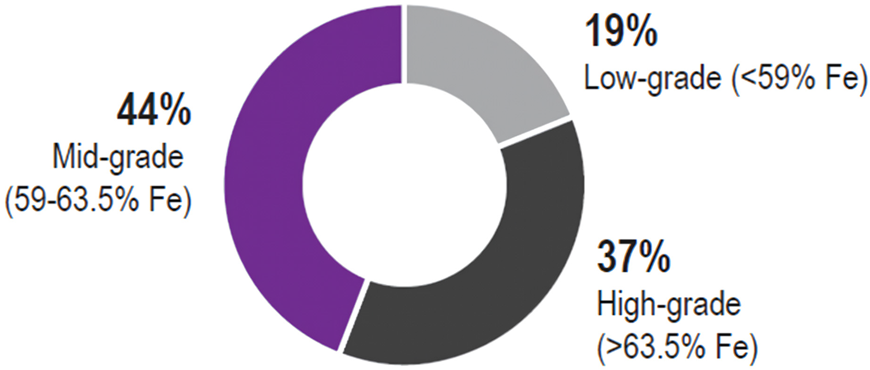
Global iron ore exports by grade. 2
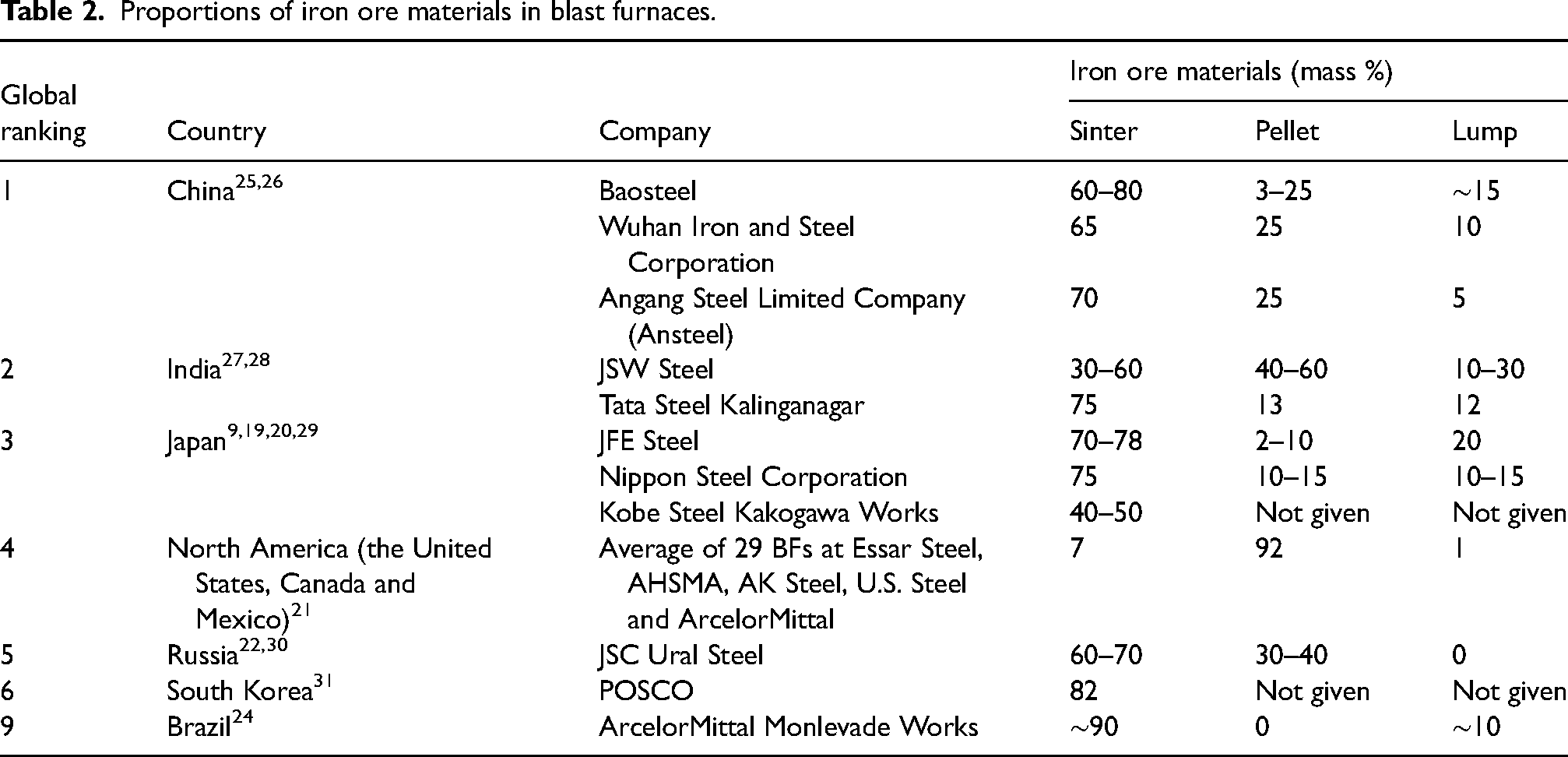
Many commercial sinter plants are exploring the potential addition of high-grade iron ore concentrates to improve sinter grade and to maintain or reduce blast furnace slag ratios and fuel rates. High-grade iron ore sinter lowers the reducing agent rate of blast furnaces, as well as decreases CO2 emission levels in the steel industry.4–9 However, the addition of ultrafine concentrates has a negative impact on green bed permeability and sintering productivity.10–14 Tables 1 and 2 show the proportion of ore concentrate used in sintering and iron ore materials in blast furnaces of some major ironmaking countries, respectively. 3 A significant amount of sinter is used in the ironmaking process globally. The data provided in Table 1 indicates that the proportion and type of concentrates used can differ across sinter plants. This variation is likely influenced by several factors, including the operational requirements of the plant, the availability of specific ore types, cost-effectiveness, and supply chain dynamics. It is anticipated that each ironmaker adjusts their use of concentrates to optimise performance, reduce costs, and adapt to local conditions, reflecting the complex interaction of technical, economic, and logistic factors in the sintering process. Note that the data given in Tables 1 and 2 may not represent the current operating conditions of the sinter plants and blast furnaces, which may change based on material availability and blast furnace operational requirements.
Proportions of ore concentrate in sintering.
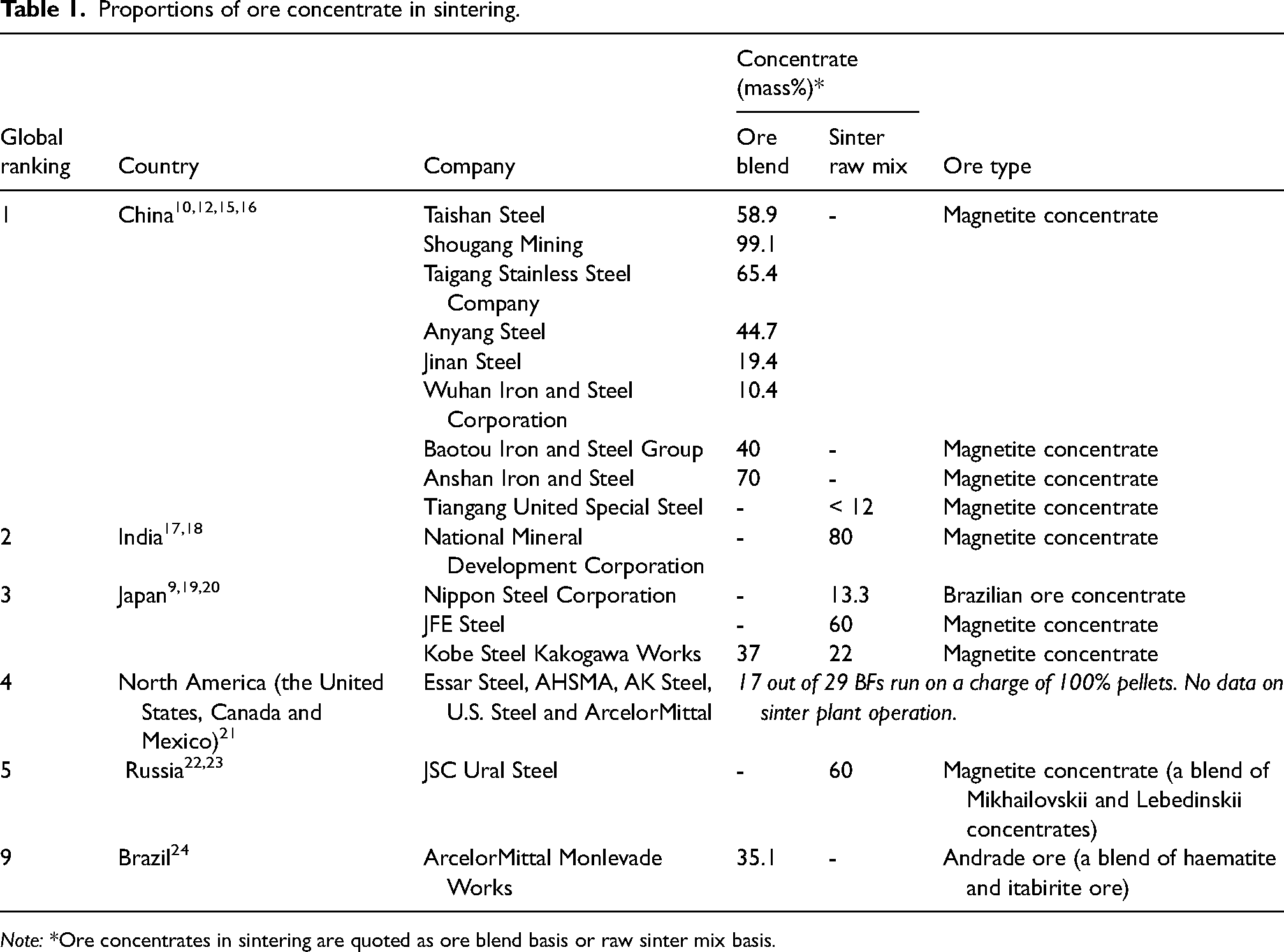
Note: *Ore concentrates in sintering are quoted as ore blend basis or raw sinter mix basis.
Proportions of iron ore materials in blast furnaces.
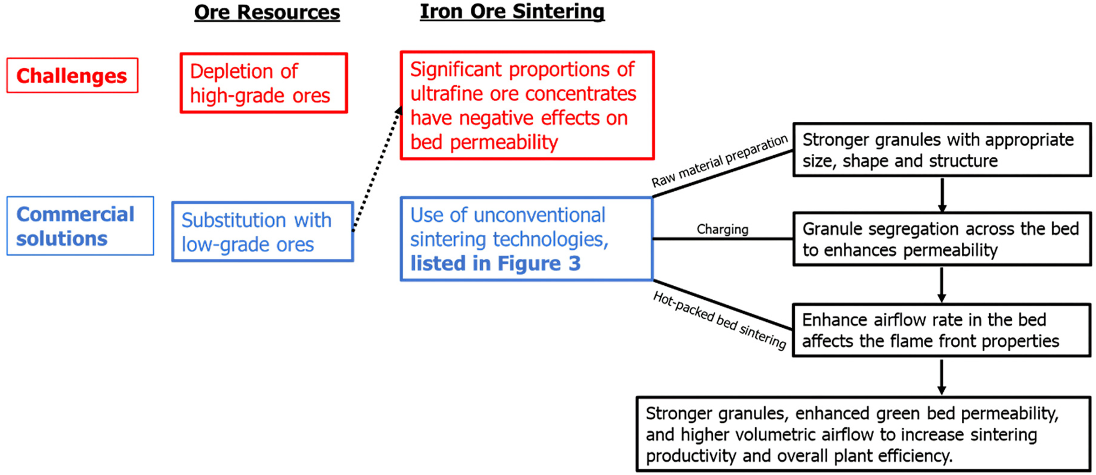
The challenge with incorporating a significant proportion of ore concentrates into the iron ore blend is the negative impact on the permeability of the green bed.10,14,32,33 The green bed permeability behaviour is thought to be due to a combination of factors that include the raw material preparation34–51 and the level of segregation in the packed bed.52–54 Furthermore, the green bed permeability affects the volumetric gas flow rate during sintering43,55,56 through changes to the flame front. Over the years, steel producers have developed several unconventional sintering technologies as countermeasures to address the negative impact of a large proportion of ore concentrate on green bed and sinter bed permeability.
Figure 2 presents a schematic illustration of how steel producers address ore resources challenges with sintering. The figure highlights some specific effects of these technologies on sintering parameter and presents a clear sequence of the interconnections between the technologies. The raw material preparation system ensures that granules produced have the appropriate size, shape and structure. Proper charging of the granules using appropriate technique is crucial for achieving the desired particle segregation, bed density and voidage, to enhance the permeability of the green bed. A higher green bed permeability indicates an increased volumetric gas flow rate during sintering, 46 such that the volumetric airflow rate through the sintering bed is related the flame front properties that affects sinter productivity and plant process efficiency.
Schematic illustration of how steel producers address ore resources challenges with sintering.
The range of technologies developed to address these challenges are presented in Figure 3 and can be categorised into three key areas – raw material preparation, granule charging, and hot-packed bed sintering systems. Additional details regarding the specific technology and process flow illustrated in this study can be found in the works of the referenced authors.
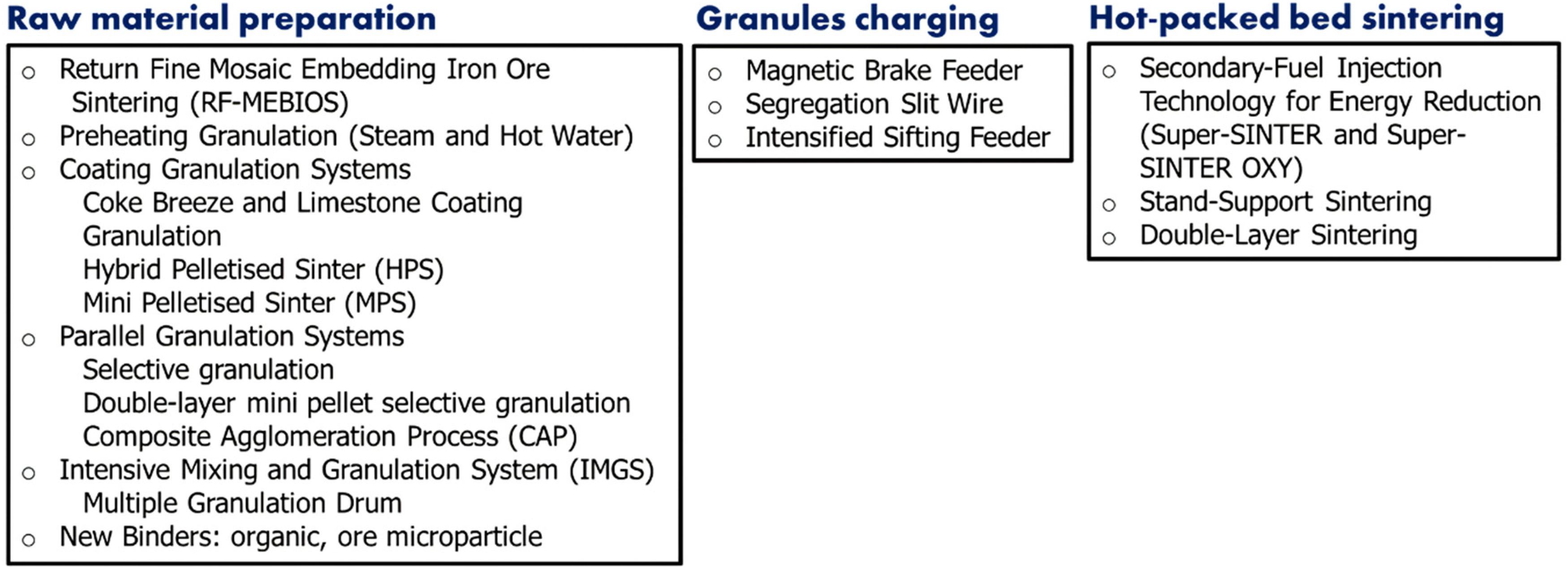
Some commercially applied sintering technologies.
This study provides a comprehensive overview of the commercially applied sintering technologies with a projection that these systems will continue to evolve with the inevitable change in iron ore resources in the future. Various technologies that can accommodate significant proportions of ultrafine ore resources have been reviewed. It was found that a combination of some of the existing sintering technologies can be retrofitted to produce high-grade sinter and reduce CO2 emission levels. The iron ore sintering process section provides an overview of the conventional sintering system, including the behaviour of magnetite during sintering and the properties of the flame front. A brief overview of the technologies involved in raw material preparation and hot-packed bed sintering systems are presented in raw material preparation and hot-packed bed sintering sections, respectively. A model sinter plant is recommended for a sustainable ironmaking process. The proposed sinter plant involves a combination of intensive mixing and granulation systems (IMGSs), ore microparticle binder, magnetic brake feeder, Super-SINTER OXY and stand support to adapt to continual changes in the sinter feedstock.
Iron ore sintering process
Iron ore sinter production involves blending and granulation of sinter raw materials that include iron ore particles (fines and concentrates), fluxes, fuel, sinter return fines, recycled iron-bearing materials from the iron-making plants, and binders to produce granules. Followed by high-temperature sintering of the granules on a sinter strand to produce a desirable porous sinter of appropriate physical, chemical, and metallurgical properties, as well as quality for iron-making blast furnace application. Figure 4 shows the schematic of a conventional sintering process. 57 The proportion of ore concentrates in ore blends in this type of system is generally below 10%.58,59
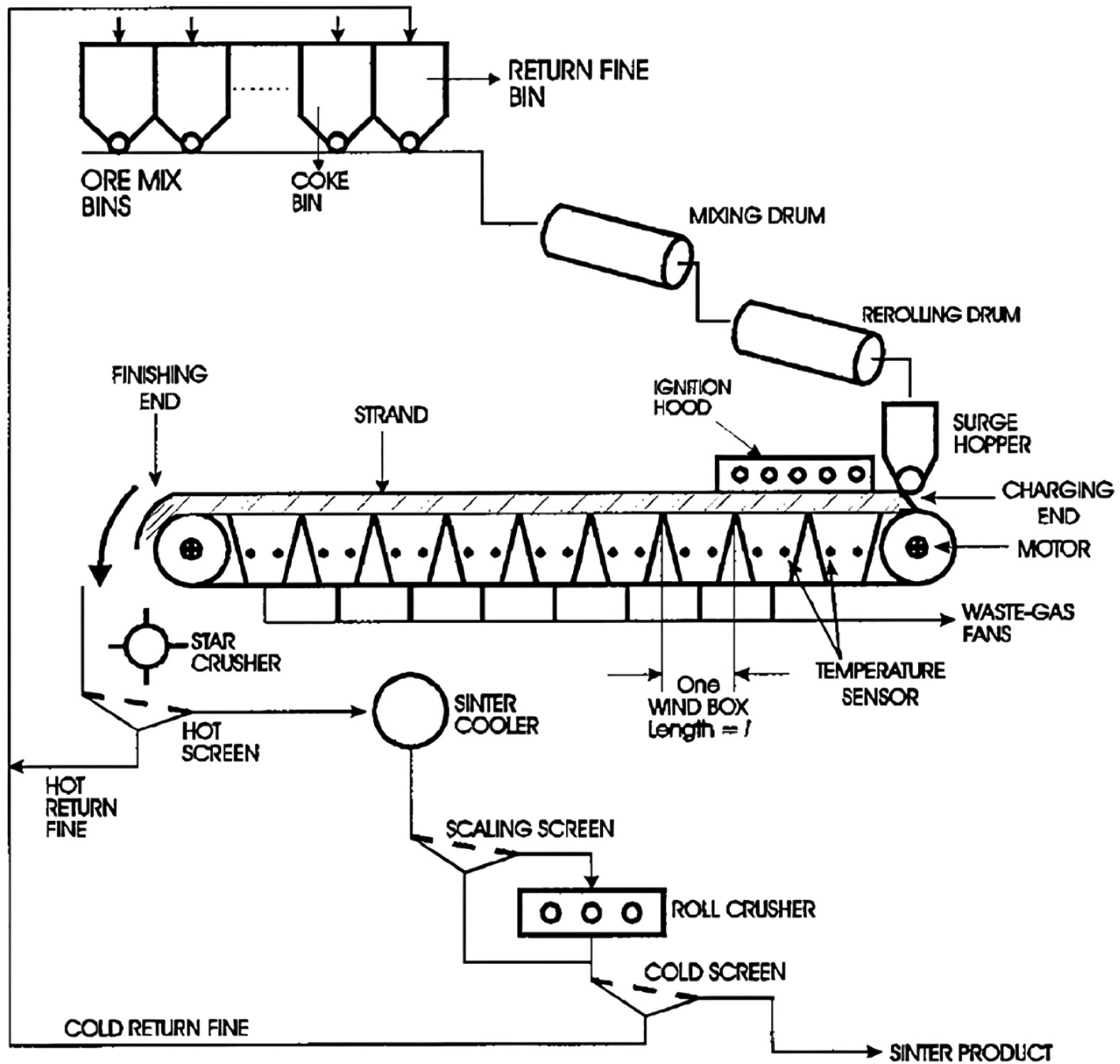
Process flow of Dwight–Lloyd sintering machine type at POSCO. 57
The raw material used in sinter production has a wide particle size distribution that could range from ultrafine to about 8 mm. The granulation mechanism involves the layering of adhering fines (<250 µm size) on the surface of nuclei particles (> 2 mm size) aided by the moistening of the particles.60–63 Figure 5 presents a schematic representation of the granulation process.
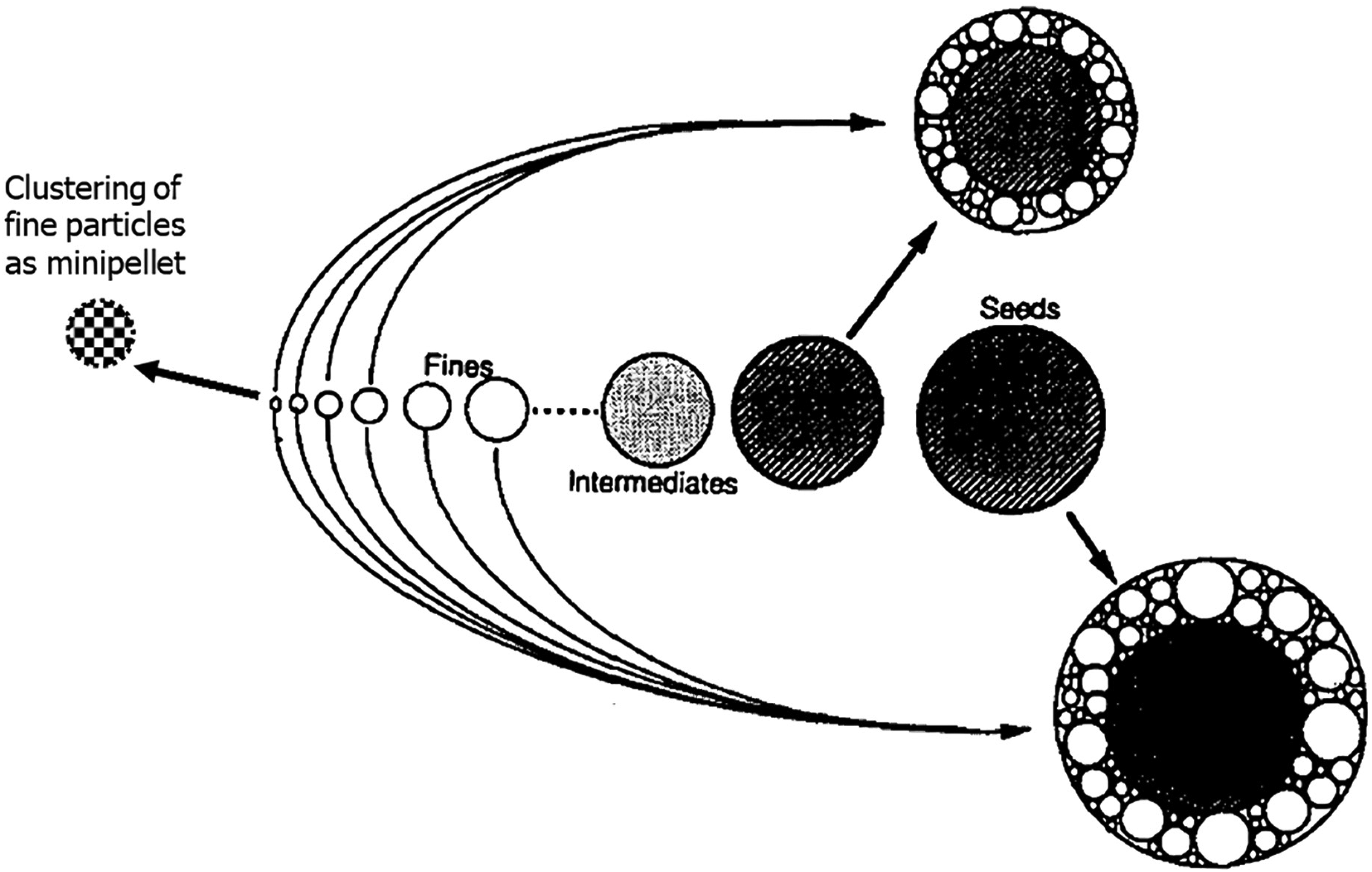
A schematic illustration of the granulation process, highlighting the formation of granules, the clustering of fine particles, and the exclusion of intermediate particles, modified from Kapur et al. 64
The granulation process occurs in a drum mixer with the addition of water, of which the amounts depend predominantly on the iron ore blend moisture-holding capacity.64–72 Ore blend moisture-holding capacity correlates with ore mineralogy, particle size and LOI components.68,73 The optimum granulating moisture content is related to ore's SiO2, Al2O3(<1 mm) and LOIT contents, as well as the <0.15 mm and 0.1–1.0 mm particle size fractions, with an empirical equation (having R2 of 0.863 and 0.807 for single ores and ore blends, respectively) given as
68
: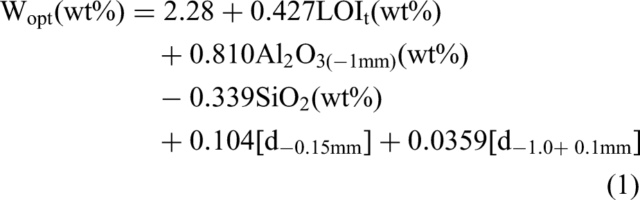
The moisture content of iron ore granules affects their properties. Physical properties such as apparent density, Young's modulus and tensile strength decrease with moisture content due to the growth of a weak adhering layer around the coarse nuclei particles.74,75 The tightening of the granule size distribution and granule deformability describe the behaviour of granules in a packed bed as a function of moisture content. 76 At a low moisture content, the adhering layer on the surface of nuclei particles is a thin and rigid layer and a further increase in the moisture content continues to tighten the particle size distribution. At the optimum moisture content, there is a balance of the tightening of granule size distribution and granule deformability. At high moisture content, the layer of adhering fine particles thickens significantly, becoming weaker and susceptible to deformation when packed in a bed under load (top-layer granules compressing the bottom-layer granules).
Magnetite behaviour during sintering
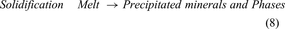
Several chemical and metallurgical reactions take place during the sintering process to produce a porous sinter mass. The reactions overlap each other occurring as solid-state and heterogeneous reactions between the melt, solids and gaseous phases which are present in the sintering zone.77,78 Hence, the following gases, gas–solid and solid phase reactions can occur:

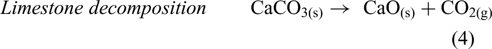
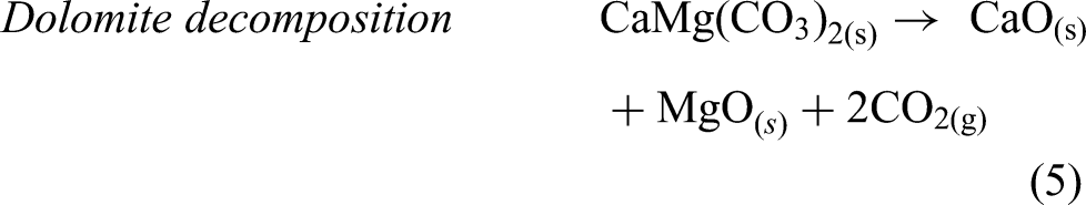


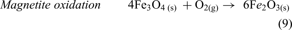
The reactions given in equations (3) to (5) contribute to CO2 emission in the sinter plant. Effective utilisation and optimisation of solid fuel in the sintering process are keys to improving productivity and achieving CO2 reduction. Theoretically, there is a potential to reduce fuel consumption with magnetite addition when magnetite particle is oxidised to haematite (equation (9)). 6 The formation of haematite from magnetite oxidation reaction is influenced by the exposure time of the particle to air at temperatures >300 °C, partial pressure of oxygen and physical attributes of magnetite particles such as size, structure, and level of impurities.6–8 Magnetite oxidation is limited in granules with a thick adhering layer, 20 in addition, the calcination, coke combustion and melt formation also restrict oxygen access to the unreacted magnetite particles.4,6,79,80
The oxidation of magnetite concentrate influences the formation of mineral phases (iron oxides, calcium ferrites (SFCA) and silicates) in the sinter.79,80 Jeon et al. 80 reported that magnetite concentrate (the Fe2+ in the unoxidised magnetite) influences the physicochemical properties of melt, SFCA structure and the assimilation behaviour of the granules. The proposed mechanism shown in Figure 6 indicates that Fe2+ substitutes Ca2+ in the SFCA formation and more Fe2O3 become available for assimilation into the melt.
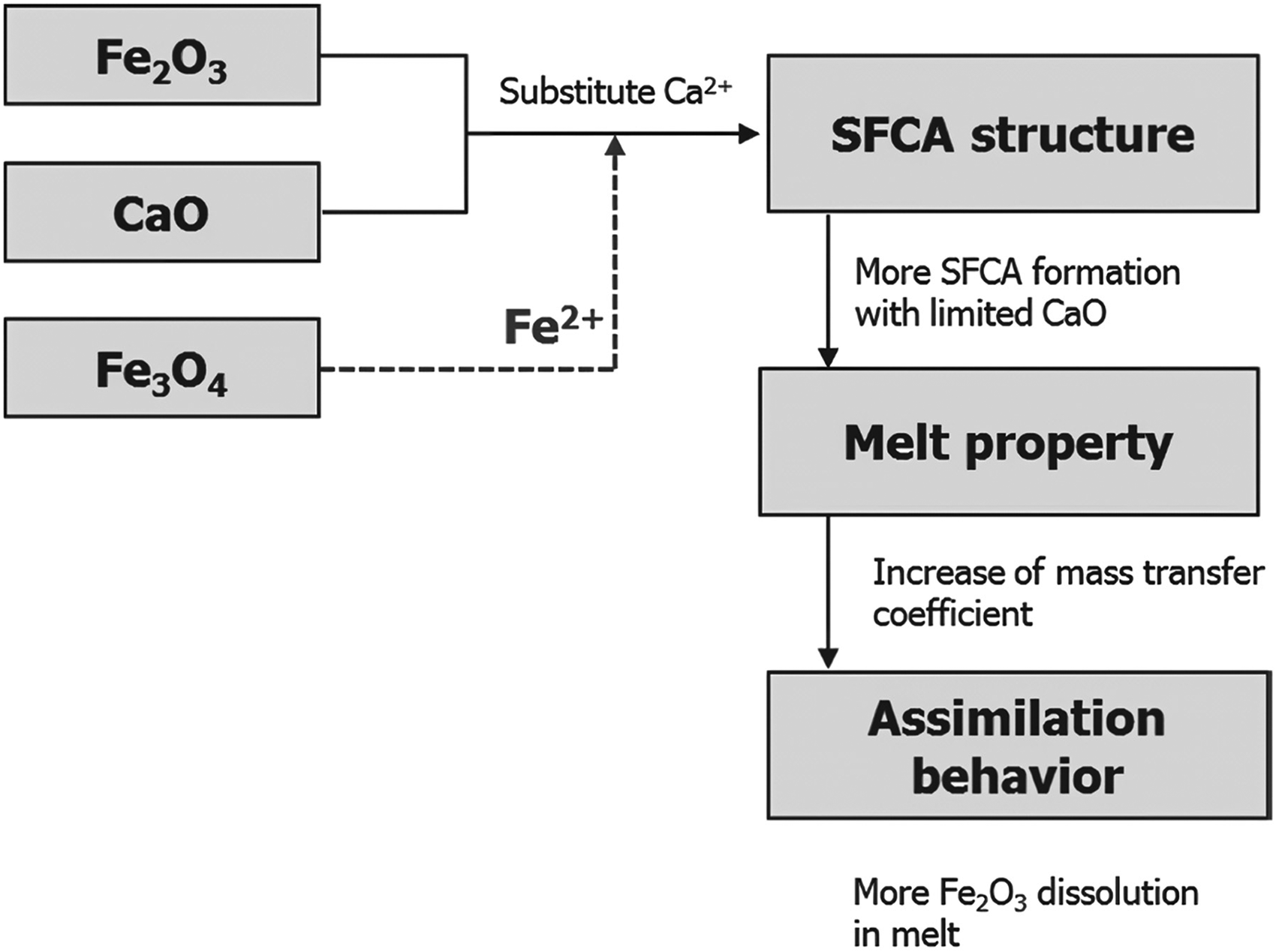
Proposed mechanism interpreting the effect of magnetite addition on SFCA formation, melt property, and assimilation of granules. 80
Flame front properties
Flame front properties are dependent on the coke rate and airflow through the packed bed during sintering.36,38–43 Coke combustion occurs only when its surface reaches a temperature of about 1000 °C in the presence of oxygen. 44 This suggests that oxygen accessibility to the coke particle depends on the capability of air to move through the packed bed. The flame front has a leading edge where coke particle combustion starts and a trailing edge where all the coke particles are entirely consumed.44,45 The presence and location of coke in the granule and its access to oxygen during the combustion process influence the flame front properties and sinter productivity.36,37
The airflow resistance in the bed influences the overall sintering process.
43
The formation of primary melt from the reactive adhering fines reduces oxygen access to the granules and requires an extended period to complete combustion.44,45,81,82 This results in the broadening of the flame front width due to an increase in the flame front resistance.
83
The overall resistance to airflow across the sintering bed is thought to be the sum of the resistances across all the zones namely44–48,50,84:
sintered (hot and cooled sinter) zone, high-temperature zone (a combination of the melt solidification zone, flame front, calcination zone and drying), and humidified zone.
The zone with maximum resistance to airflow controls the sintering process. It is well-known that the sintered bed structure is highly porous with little or no resistance to airflow through it, such that any significant resistance to airflow rate across the sintering bed happens either within or from a combination of both the humidified and high-temperature zones.44,45,48,50,84–86 The contribution of the high-temperature zone is more substantial compared to the humidified zone.44,45 The high-temperature zone flow resistance depends on sinter bed temperature and high-temperature zone structure, which is related to melt volume, melt properties, bed voidage, airflow rate and high-temperature zone thickness. 39
At the leading edge of the flame front, drying and calcination occur in the granules. Consequently, the granules’ moisture content reduces resulting in a breakdown, fines filling up bed voidage, and a significant loss in the bed voidage contributing to the pressure drop across the drying and calcination zone.44,45,70,87 The moisture content of granules is important as more water is required to granulate ore blends containing a high proportion of particle size close to 0.1 mm. 68 The humidified bed resistance increases when green bed permeability is improved with excess moisture. 68 High moisture granulation of sinter blends followed by a preheating step is used as a countermeasure to eliminate over-wetted granules and improve granule strength, bed permeability and sinter productivity.12,15,23,88,89 However, this step is energy-demanding and increases CO2 footprint.
Raw material preparation
The granulation process is an important step in the raw material preparation process. Ultrafine iron ore particles are however quite challenging to granulate in a drum mixer hence several technologies have been developed as countermeasures. Where applicable some of the commercially applied countermeasures have been further categorises into (i) return fine mosaic embedding iron ore sintering (RE-MEBIOS), (ii) preheating granulation, (iii) coating granulation, (iv) parallel granulation, (v) intensive mixing and granulation, and (vii) new binders, based on their operational similarities, offering a clearer representation of how related technologies function within the broader context of the sintering process.
Return fine mosaic embedding iron ore sintering
The mosaic embedding iron ore sintering (MEBIOS) is a technique proposed by the Iron and Steel Institute of Japan research group on porous meso-mosaic texture sinter to use significant proportions of low-grade goethite iron ore resources. 90 A schematic of the conceptual illustration of the MEBIOS process is presented in Figure 7. 91 The process arranges dense pre-granulated pellets that do not easily deform during sintering within the matrix of a sinter mixture to create a ventilation route in the sintering bed.90–95
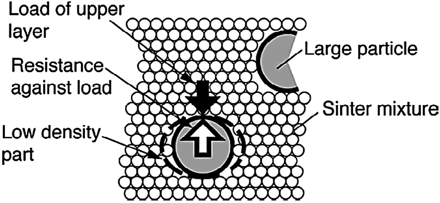
Illustration of the mosaic embedding iron ore sintering process showing a large dense particle and sinter mixture in a packed bed. 91
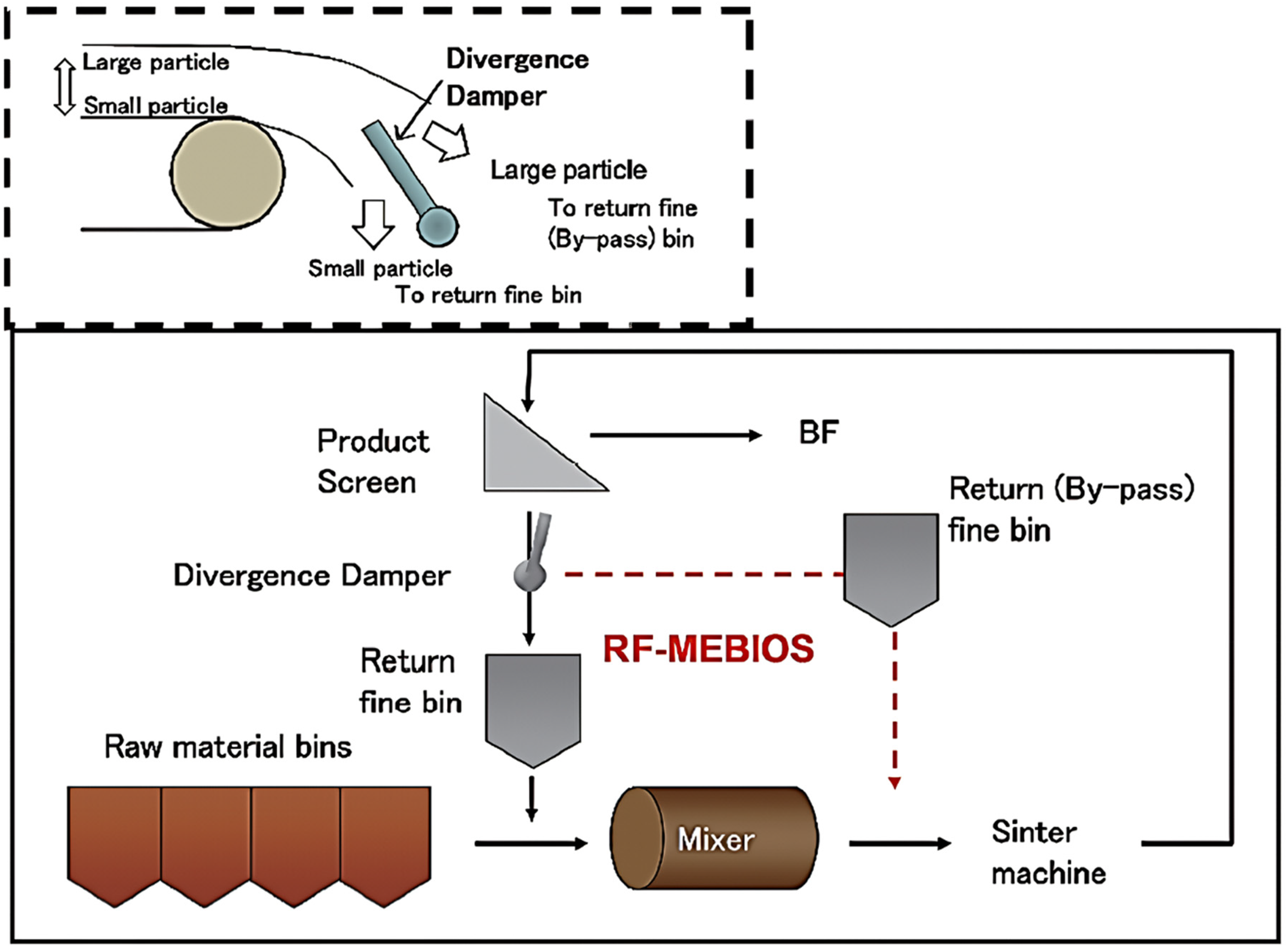
Nippon Steel amends the MEBIOS process to use return fines as the dense particle in a process known as RF-MEBIOS. A proportion of the return fines is added to the granules before it is charged into a sintering machine. The flow diagram of the RF-MEBIOS process is presented in Figure 8.92,96 The RF-MEBIOS process has been installed at the Wakayama, Kashima, Kokura, Kimitsu and Yawata Works.90,93,94,96,97 The addition of return fines to the wet granules increases particle size and enhances bed permeability. This is due to a decrease in the bulk density caused by higher friction between the dry return fines and wet granule particles, see Figure 9. 96 An increase in the proportions of return fines improves sinter productivity, as presented in Figure 10, 92 due to an improvement in the flame front speed (FFS).91,92,96
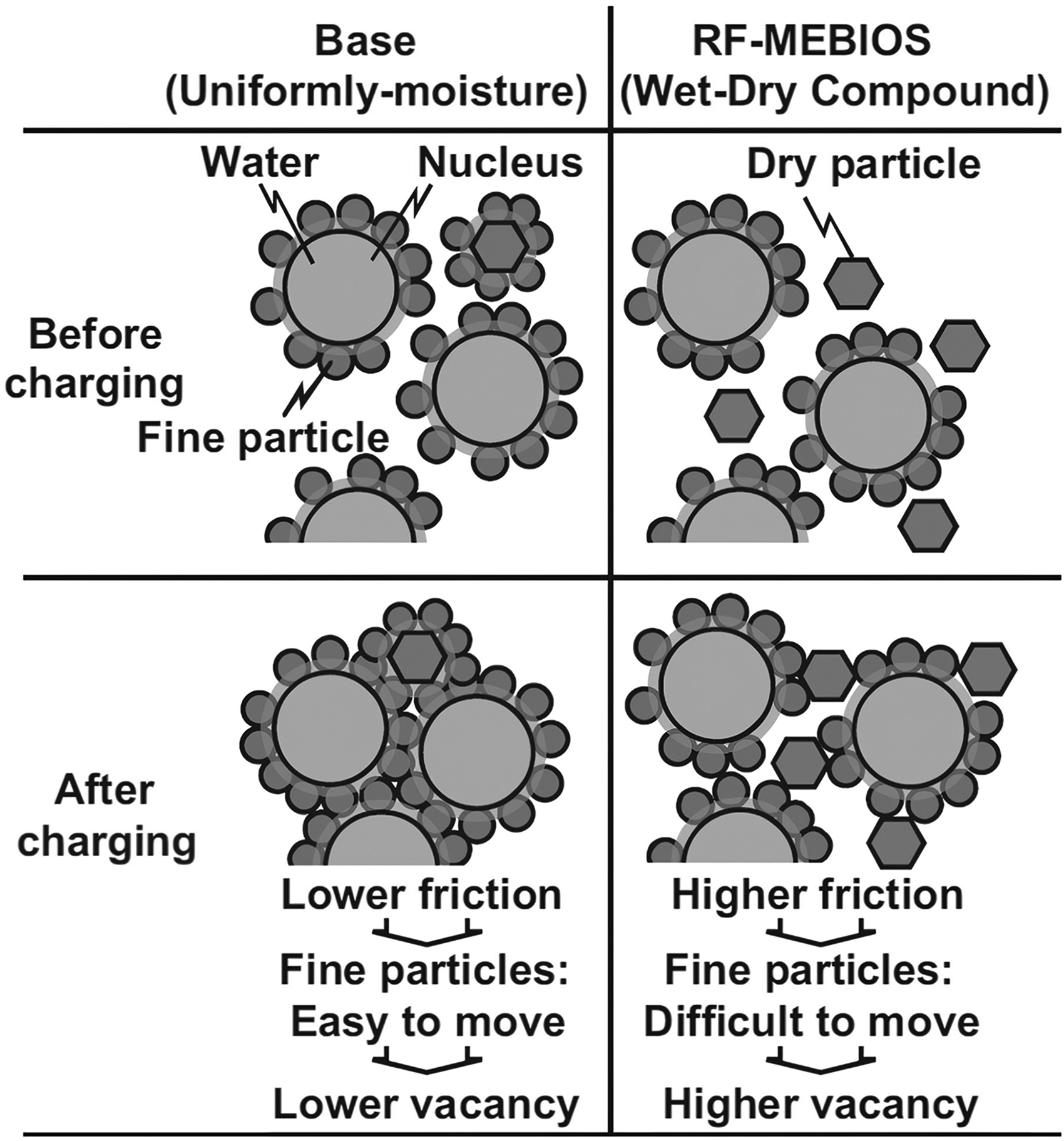
Effect of return fine-mosaic embedding iron ore sintering (RF-MEBIOS) process on sinter bed permeability. 96
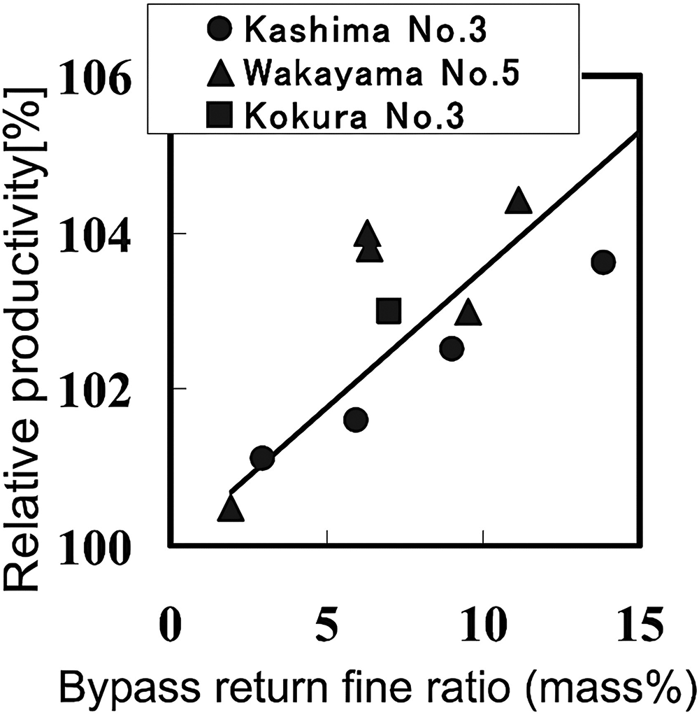
Effect of return fine mosaic embedding iron ore sintering (RF-MEBIOS) on Nippon Steel's sinter productivity. 92
Preheating granulation (hot water and steam)
Some examples of the commercial applications of preheating granulation include Tiangang United Special Steel (China),
15
ShouGang JingTang Iron and Steel Plant (China),88,89 WISCO (China)
12
and JSC Ural Steel (Russia).
23
Preheating granulation is a countermeasure technique that removes excess moisture in granules to improve the air permeability of the sintering materials layer. This makes the material temperature higher than the dew point temperature, and the moisture in the materials does not condense into liquid water.
98
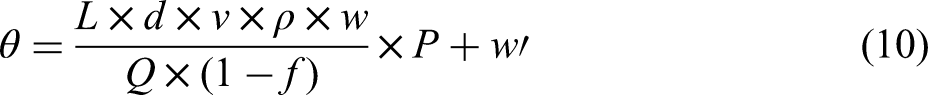
The moisture content of the exhaust gas in the lower part of the sintering materials layer is given as
15
:
Hot water granulation
A schematic illustration of the hot water granulation process at JSC Ural Steel is given in Figure 11. 23
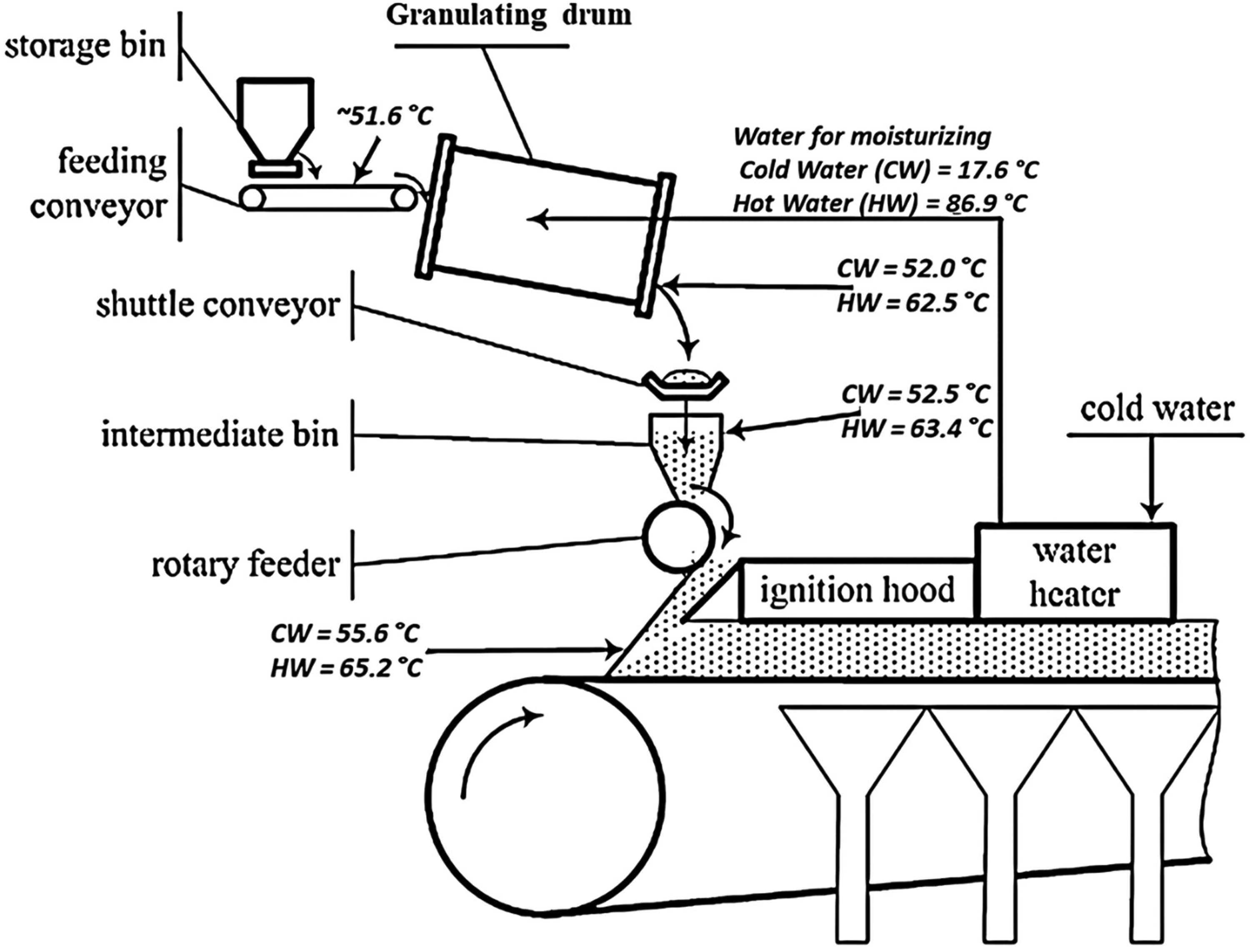
Illustration of the JSC Ural Steel sinter plant showing hot water granulating process. 23
In the JSC Ural sintering process, the proportion of fine-grained ore concentrates (a blend of Mikhailovskii and Lebedinskii concentrates) in the sinter mix is about 60 mass% with the burnt lime consumption rate at about 30 kg·t–1 sinter.22,23 Hot return is fed at a temperature of 350 °C to 400 °C to preheat the sinter raw mix to 51.6 °C, followed by hot water spraying in the granulation drum to raise the granule temperature to 62.5 °C. A further increase in the material temperature to 65.2 °C is attributed to an exothermic reaction of lime. Hot water granulation was carried out for a month on sinter machine No. 1 (sintering area 84 m2; maintaining a 250 mm bed height). 23 However, this study did not report whether the operation was conducted in summer or winter. Sinter productivity increases by 3.2%, from 1.152 t·m–2·h–1 (cold water) to 1.189 t·m–2·h–1 (hot water) due to an improvement in the FFS. 23 The manufacturing and installation cost of the water heater system at the JSC Ural Steel is less than 10,000 euros. 23
Steam and hot water granulation
A schematic illustration of the steam and hot water granulation process at the Tiangang United Special Steel is presented in Figure 12. 15 In the production of a 1000 mm depth sintering bed at the Tiangang United Special Steel, the proportion of iron ore concentrates with a particle size fraction < 1 mm size is < 12%. In this process, hot water is sprayed into the mixing drums; superheated steam recovered from the flue is injected into the secondary mixing drum; and superheated steam from the sintering machine head is sprayed on the granules. This stabilises the sinter mix temperature at 76–82 °C, above the dew point temperature of 62 °C. 15 This technology enhances the granule strength resulting in an improvement in bed permeability and stability at a bed depth of 1000 mm at the two 260 m2 sintering machines, maintaining a high productivity level of 1.89 t·m–2·h–1. 15 The tumble index (TI), reduction index (RI) and reduction degradation index (RDI + 3.15) of the sinter are 78.2%, 87.2% and 74.2%, respectively. 15
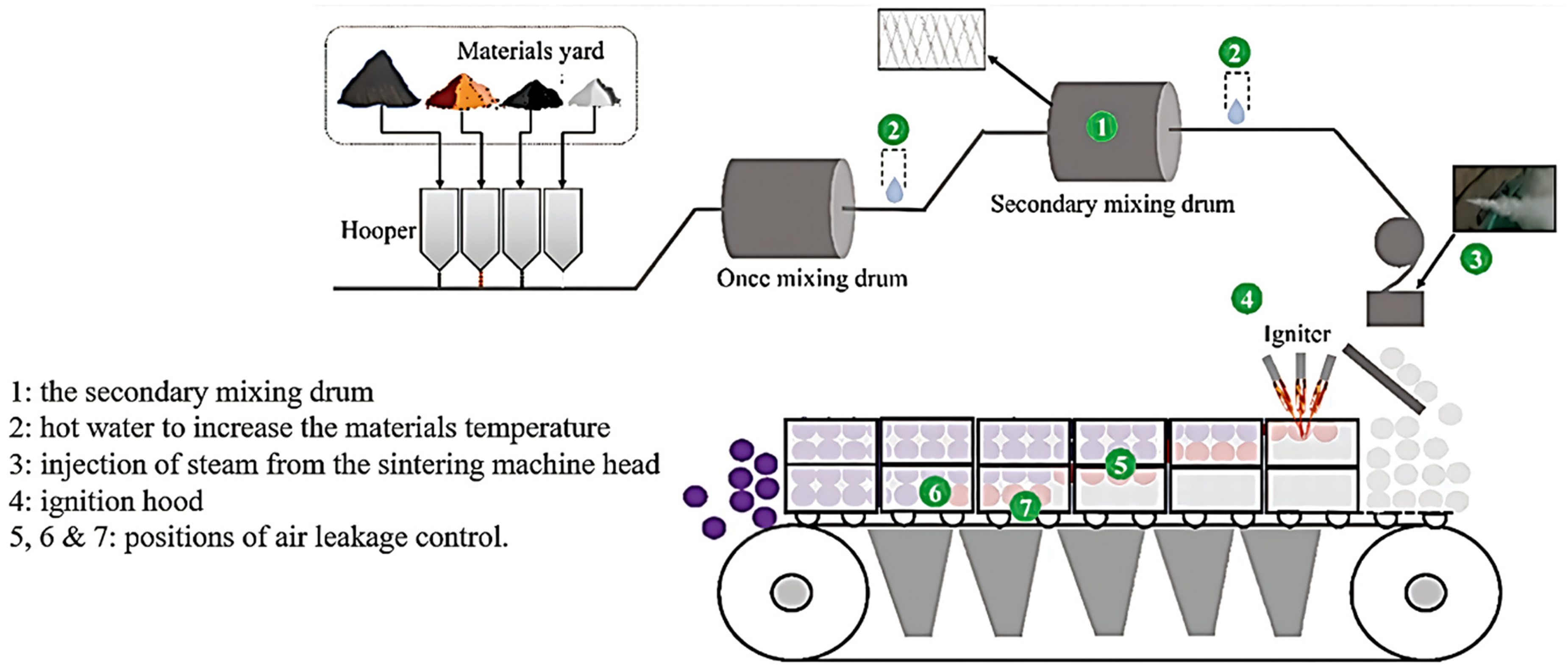
Steam and hot water granulation at the Tiangang United Special Steel. 15
Coating granulation systems
Coke breeze and limestone coating
The coke breeze and limestone coating granulation is a process developed by JFE Steel and installed at six of JFE's seven sintering machines (Keihin No. 1, Kurashiki No. 2 and 3, Chiba No. 4, Fukuyama No. 3 and 4), except Fukuyama No. 5 sintering machine.19,29,99,100 The Fukuyama No. 5, with an effective grate area of 550 m2, has a hybrid pelletised sinter (HPS) process. 19 A schematic of the process flow of the coke breeze and limestone coating granulation process at JFE's Kurashiki No. 2 sinter machine is presented in Figure 13. 29
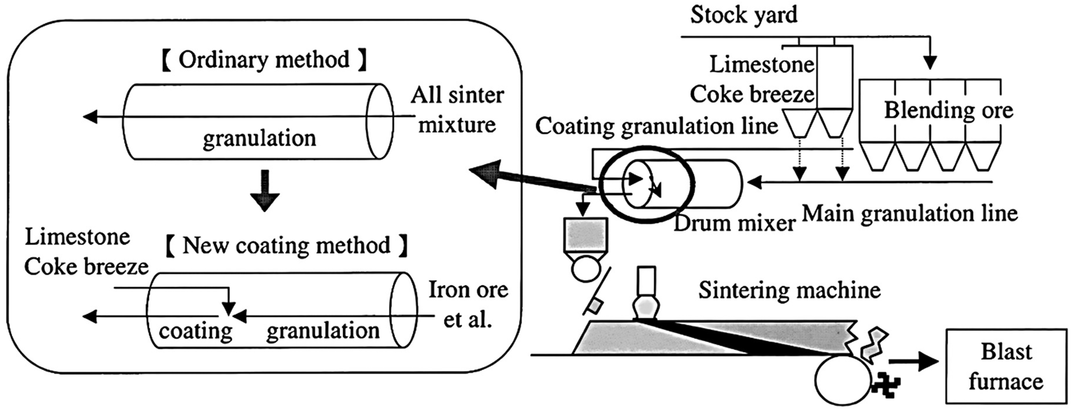
Process flow of coke breeze and limestone coating granulation at JFE's Kurashiki No. 2 sinter machine. 29
With this process, iron ore blend containing up to 75% low-grade limonite ore, return fines, and some sinter mixtures are granulated in a drum mixer, followed by coke breeze and limestone coating. 29 The green granules are mainly ore nuclei enclosed with adhering layers of coke and limestone, resulting in an increase in the granule size, a decrease in the burn through point (BTP), and an improvement in the bed permeability. The pallet speed increases from 2.80 m·min–1 to 2.95 m·min–1 to maintain a constant BTP resulting in ∼3% improvement in the sinter productivity from 1.42 t·m–2·h–1 to 1.46 t·m–2·h–1 as presented in Figure 14. 29
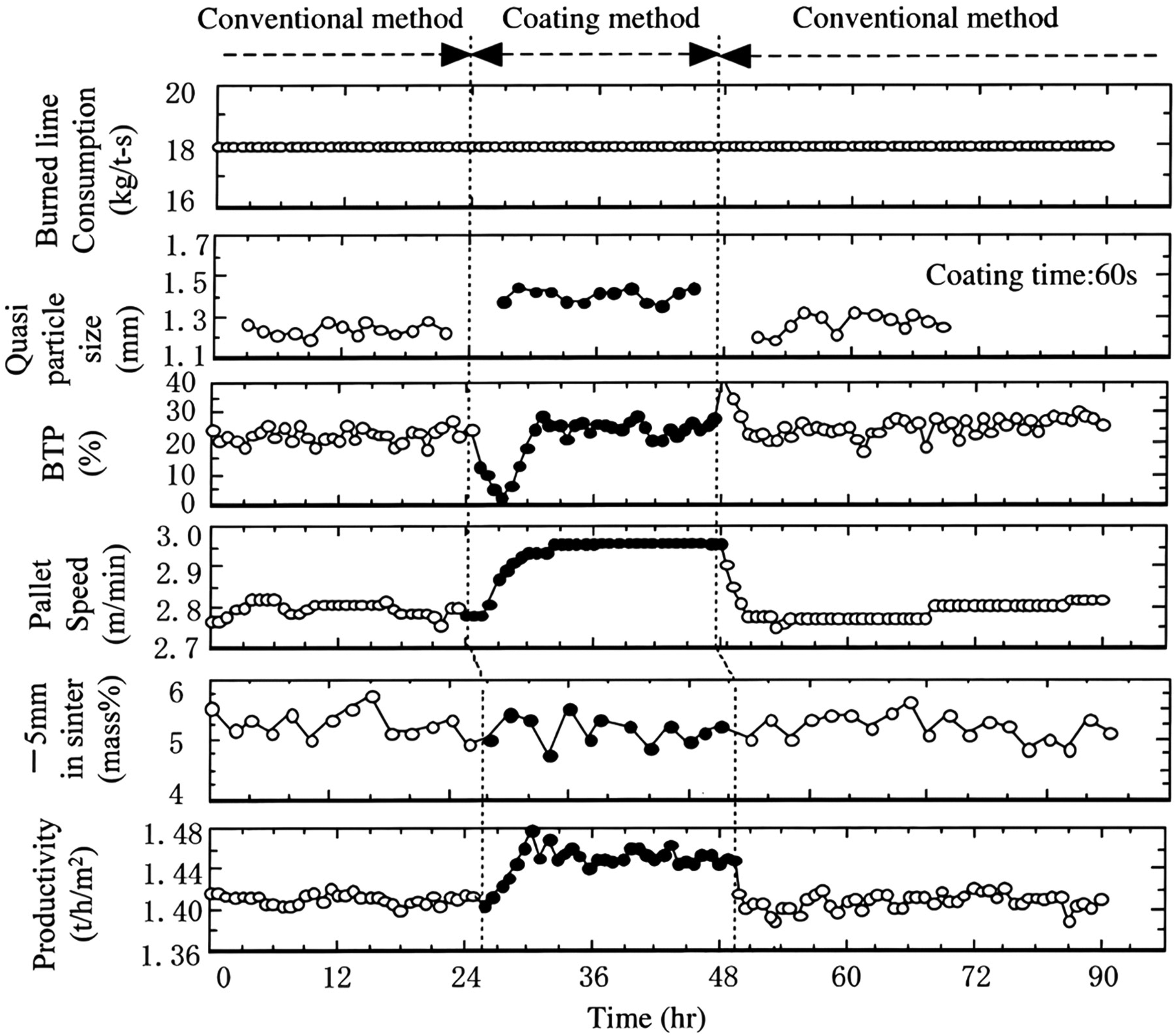
Effect of coke breeze and limestone coating granulation on sinter productivity at the JFE's Kurashiki No. 2 sinter machine. 29
The coating formation time affects the sinter productivity and quality. 29 In their work, a coating granulation time of 40 s promotes optimum productivity, as presented in Figure 15. 29 At a coating granulation time of less than 40 s, the distribution of coke breeze and limestone particles at the granule surface is inadequate and spotty, resulting in a decrease in the strength of the sinter cake and an increase in the return fine ratio. Also, when the coating granulation time is extended to 80 s, bed permeability and sinter productivity decrease, and the reducibility of the sinter deteriorates. After the optimal coating time, coke breeze and limestone particles on the surface of the granules are physically absorbed into the granule structure resulting in a decline in the bed permeability and sinter productivity. 29
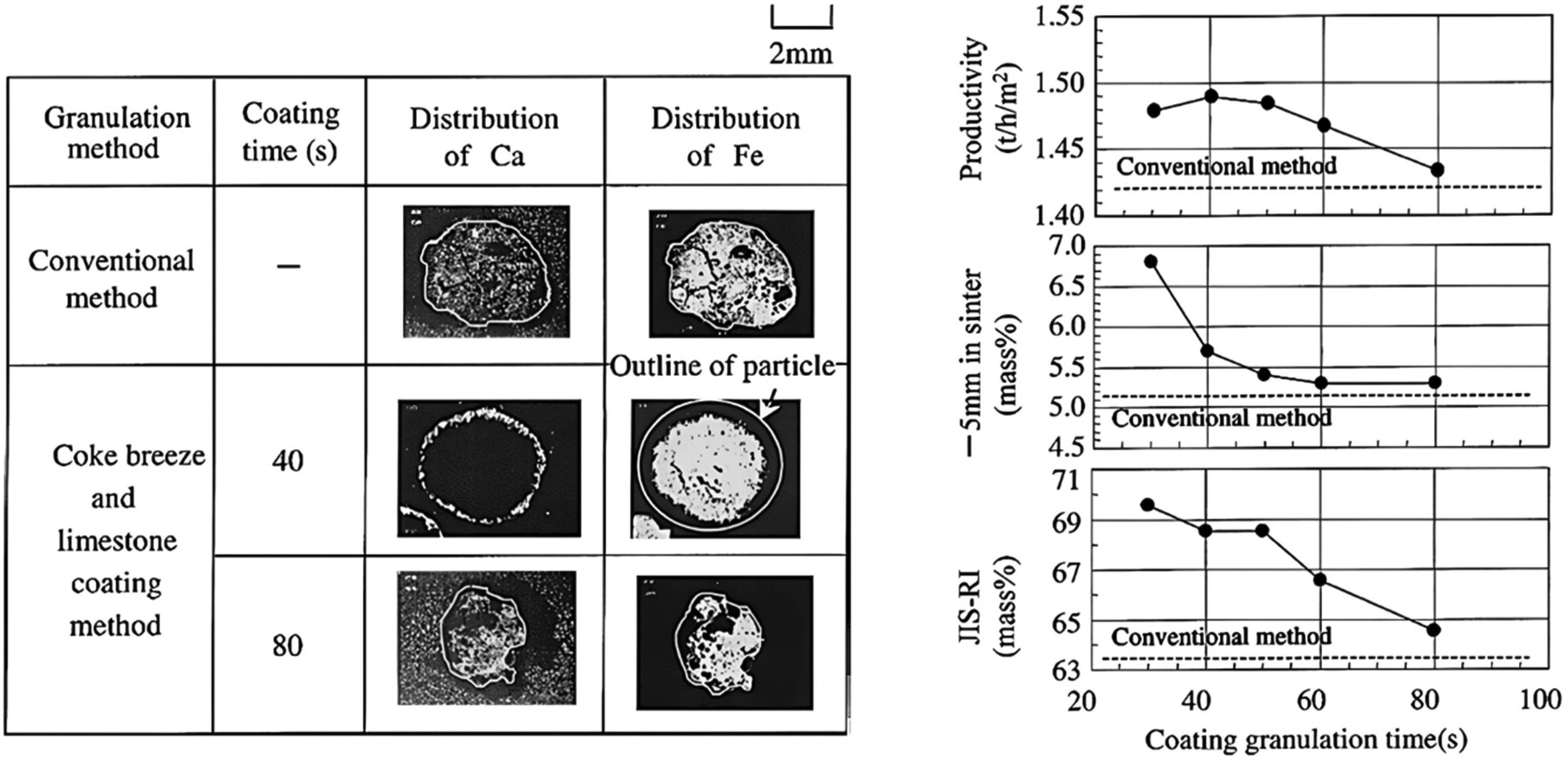
Effect of coke breeze and limestone coating granulation time on sinter productivity and quality at the JFE's Kurashiki No. 2 sinter machine. 29
Coke breeze and magnetite concentrate coating
The coke breeze and magnetite concentrate coating granulation is a process trialled at the JFE's Fukuyama No. 4 sinter plant with a suction area of 400 m2. 101 The proportion of magnetite concentrate is 10 mass% of the ore blend. In this process, iron ore blend, and some sinter mixtures are granulated in one drum mixer, followed by coke breeze and magnetite coating in another drum mixer. The green granules are mainly ore nuclei enclosed with adhering layers of coke and magnetite concentrates. The importance of coating granulation time is acknowledged in this work; however, the residence time is not stated. Also, insufficient coating with magnetite concentrate is reportedly a problem. During sintering, the oxidation of magnetite particles is thought to provide a reasonable heat supply to the process. Coke consumption rate decreases to 41 kg·t–1 sinter in comparison to the conventional method which uses 45 kg·t–1 sinter. The reduction in coke consumption is due to better combustion efficiency despite insufficient coating by magnetite concentrate. The sinter qualities (TI, RI, and RDI) improve due to the presence of micropores in the size range of 10–100 μm. There is however no publicly available data to confirm if this process has been employed in a full-scale commercial application at JFE or any other commercial sinter plants. 101
Hybrid pelletised sinter
HPS is a process developed by JFE Steel and installed at the Fukuyama No. 5 Sinter Plant to accommodate 60% pellet feeds in the ore blend. 19 The Fukuyama No. 5 Sinter Plant was re-modelled into an HPS Plant in 1988 with a capacity of 6 million tons per year. The process flow diagram of the JFE's HPS process is presented in Figure 16. 19 The JFE process has been installed at the ArcelorMittal Monlevade Works HPS Plant (in 2003) to process 100% Andrade iron ore (a blend of haematite and itabirite ore; < 150 μm size is 35.12 mass%). 24
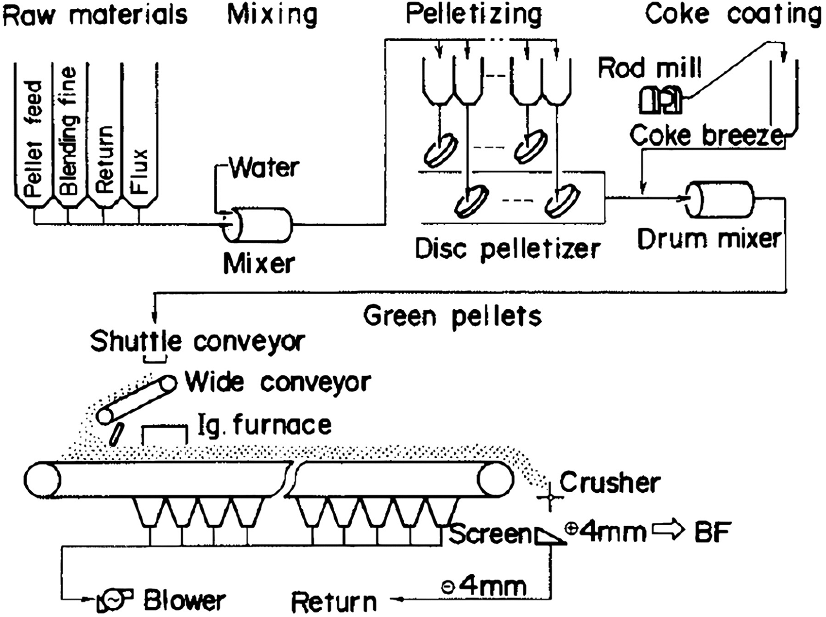
Process flow of hybrid pelletised sintering at the JFE's Fukuyama No. 5 sinter plant with a capacity of 6 million tons per year. 19
In the HPS process, iron ore concentrates, iron ore raw materials, limestone and burnt lime are first mixed, then pelletised to produce green pellets (3 to 10 mm in size). The green pellets are carbon-coated before sintering. During the sintering of coke-coated pellets, melt and pore formation are enhanced. 102 HPS installation at JFE Fukuyama No. 5 sinter plant improves the RDI and RI, see Figure 17. 19 Sinter productivity increases due to an improvement in sinter yield.
Effect of hybrid pelletised sintering on operational data and productivity at Fukuyama No. 5 sinter plant. 19
Mini pelletised sinter
The mini pelletised sinter (MPS) is a process developed by the Shougang and Central South University. The MPS is like the JFE's HPS process, where the sinter feed is pelletised before coating in a drum mixer. 12 The key contrast in the MPS and HPS processes is the coating materials, MPS uses coke breeze and limestone while HPS uses coke breeze. MPS is widely used in many sinter plants in China to accommodate significant proportions of domestic magnetite concentrates, as presented in Figure 18. 12
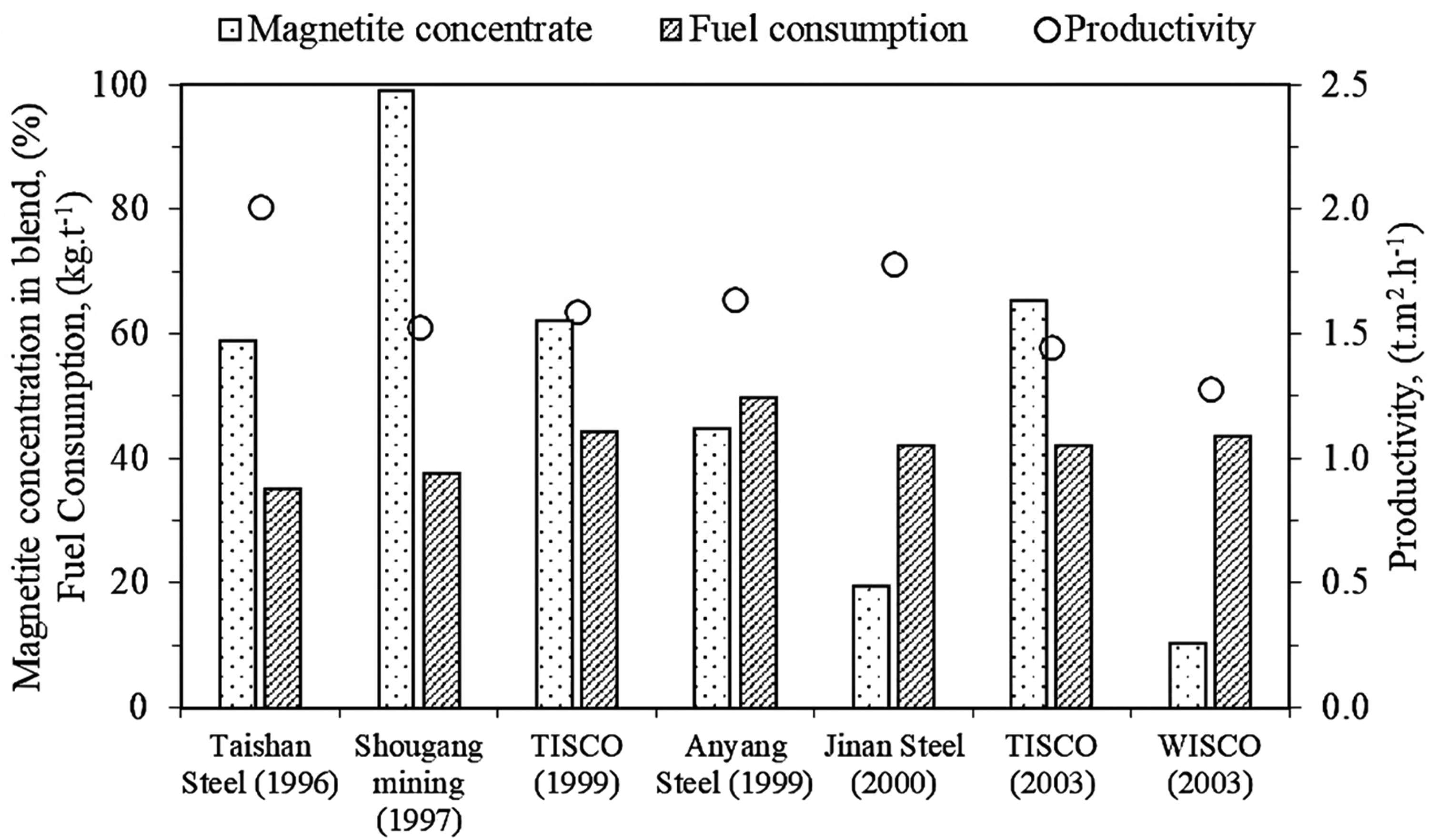
Commercial installation of mini pelletised sintering process in sinter plants in China. 12
The data presented in Figure 18 is specific to individual facilities. It is presumed that each of these ironmaker tailored their use of concentrates to enhance performance, minimise costs, and accommodate local conditions such as proportion of dusts and other revert materials used in sintering. Consequently, a direct relationship between the variables is not apparent.
Parallel granulation systems
Selective granulation
Selective granulation is a process developed by Nippon Steel and installed at the Kashima No. 2 Sinter Plant in 1986, to improve the permeability of the sintering bed and enhance the RDI of sinter using low-CaO (return fines, coke breeze and coarse iron ore fines) and high-CaO (limestone and <500 μm iron ore fines) raw materials. 103 This process has been installed at the Oita No. 2 (1994), Tobata No. 3 (1996), Oita No. 1 (1997), Kimitsu No. 3 (2002) and Wakayama No. 5 (2011) Sinter Plants, to improve the sintering performance of low-grade iron ore resources.104–107 The conceptual design of Nippon Steel's selective granulation process is presented in Figure 19. 104
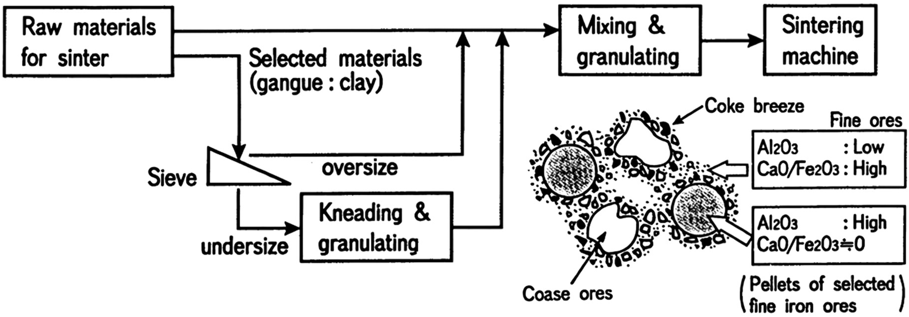
Illustration of Nippon Steel's selective granulation. 104
The granules nucleus and adhering layer have low-CaO/high-Al2O3 and high-CaO/low-Al2O3, respectively. The green granules are strong, do not disintegrate during dynamic packing, and improve the permeability of the sintering bed. During sintering, melt formation is enhanced due to the preferential segregation of flux in the adhering fines. The composition of the calcium ferrite bonding phase around the coarse iron ore particles is high in Fe2O3 and CaO to control Al2O3 concentration in the sinter.104,108 A high concentration of Al2O3 in melts aids the formation of a columnar SFCA with an inferior strength on cooling. 109 The effect of selective granulation on sintering characteristics is presented in Figure 20. 110
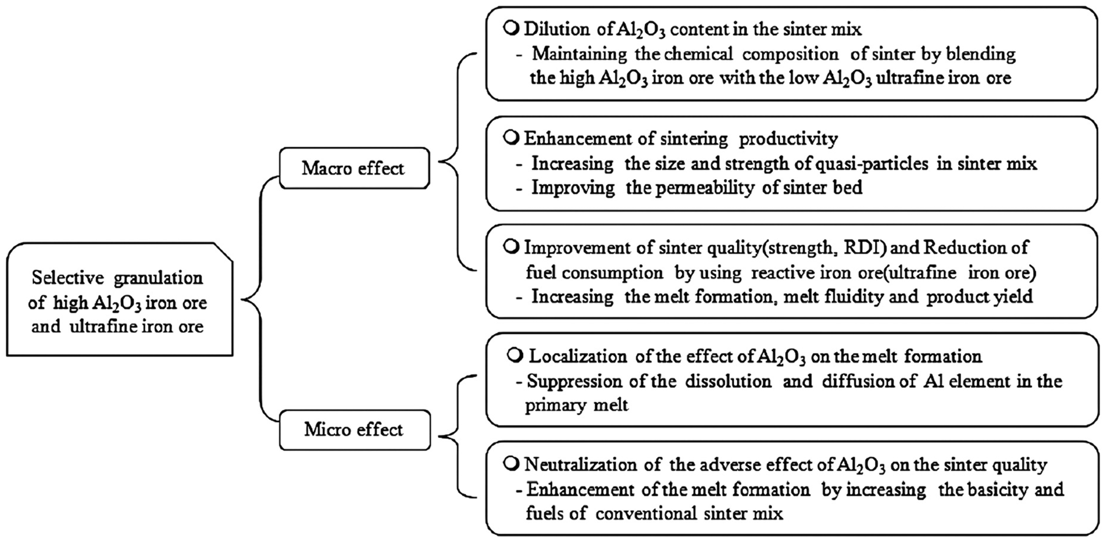
Influence of selective granulation on sintering characteristics. 110
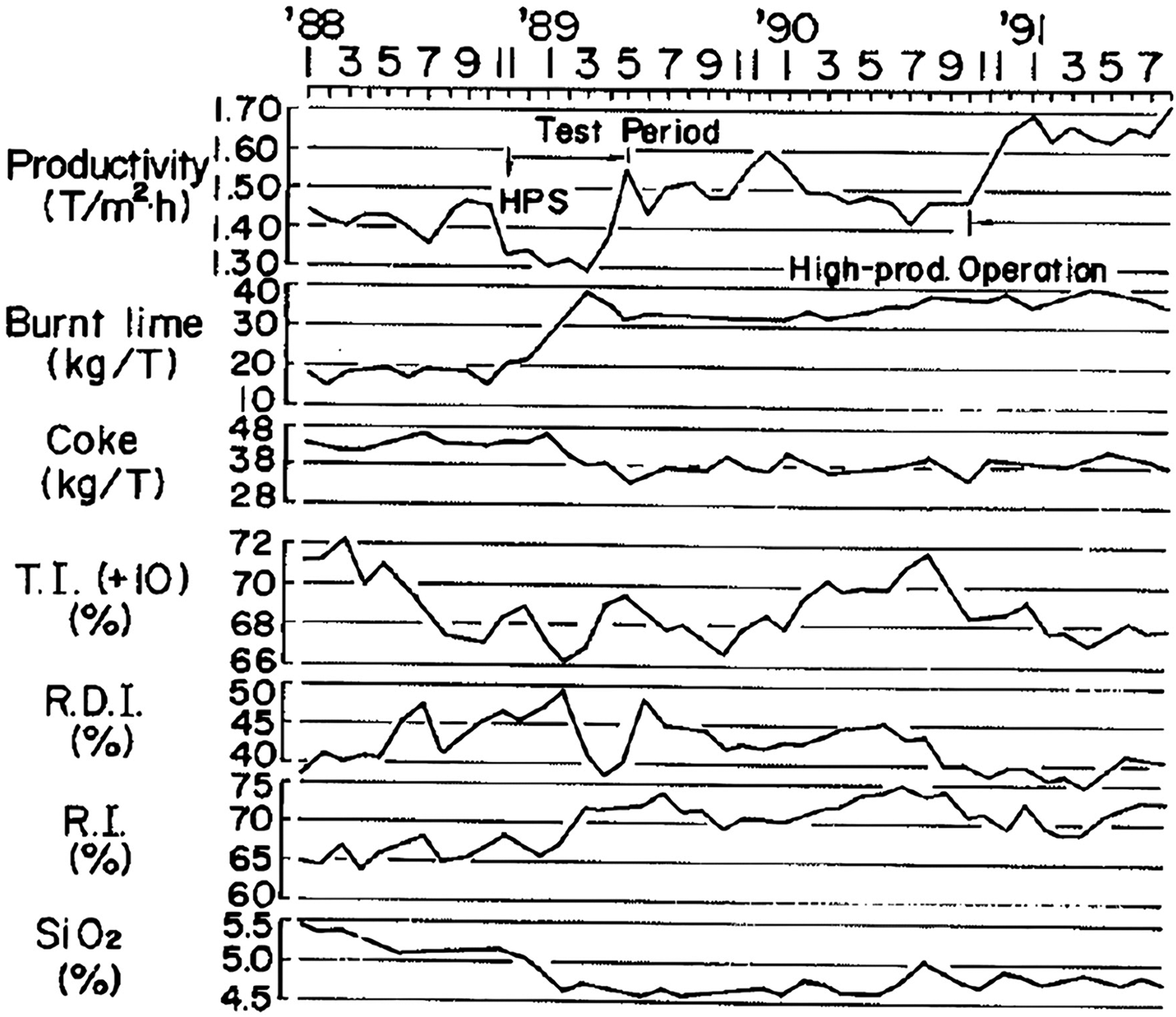
Some operational data collected over a period, at the Nippon Steel's Kashima No. 2 Sinter Plant is presented in Figure 21. 103 Sinter productivity increases due to an improvement in the sinter yield. The coke consumption rate decreases to 43 kg·t–1 sinter compared to 47 kg·t–1 in the conventional method.103,108
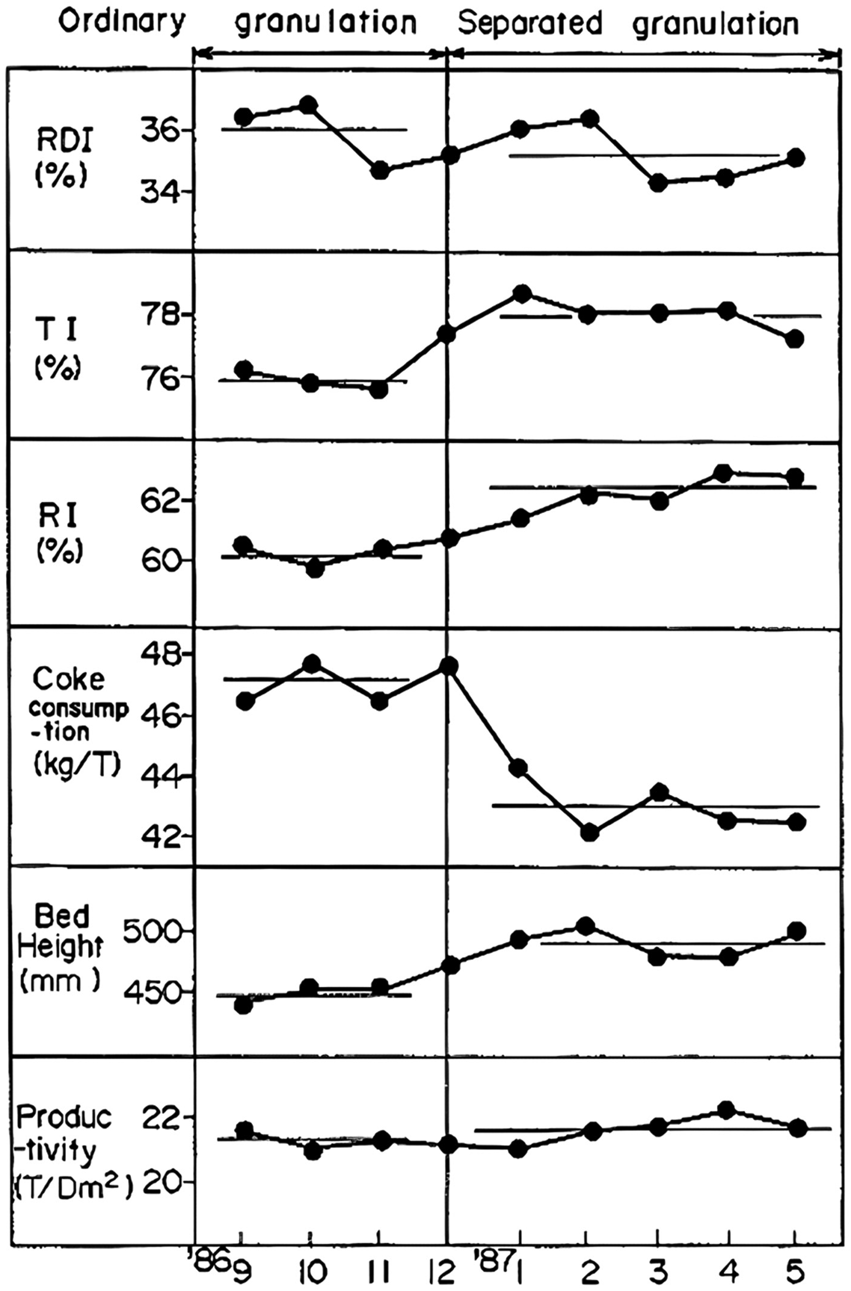
Operation data from Nippon Steel's Kashima No. 2 sinter plant. 103
Double-layer mini pellet selective granulation
The double-layer mini pellet selective granulation is a process developed by Kobe Steel's Kakogawa Works to accommodate 22 mass% magnetite concentrates in the sinter blend. 20 The flow diagram of the process is presented in Figure 22. 20 In this process, significant amounts of magnetite concentrate, and coarse return sinter fines are granulated in one drum to form mini pellets, while haematite ore fines, fluxes, coke breeze, and return sinter fines are granulated in another drum to form the conventional granules. The mini pellets have return sinter fines as the nuclei and magnetite concentrates as the adhering fines. The mini pellets and green granules (both of size range between 3 and 5 mm) are mixed before sintering.
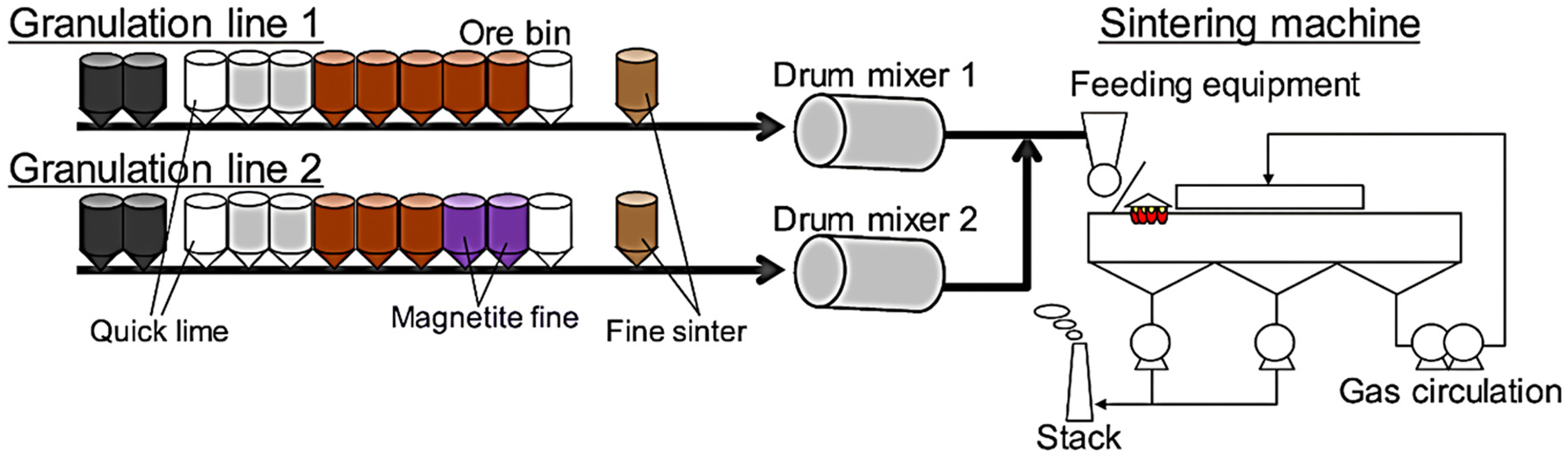
Process flow of double-layer mini pellet selective granulation at Kakogawa Works. 20
Operational data at Kobe Steel's Kakogawa Works is presented in Figure 23. 20 Comparing conventional granulation (12 mass% magnetite concentrates fines in the raw sinter mix) and the double layer mini pellet selective granulation (22 mass% magnetite concentrates fines in the raw sinter mix), sinter productivity increases by about 5%, from 575 t·h–1 to 604 t·h–1 (suction area not stated), while coke breeze consumption decreases from 4.09% to 3.83%. Sinter productivity increases due to an improvement in the FFS. The reduction in the coke rate indicates that the magnetite particles were sufficiently oxidised to supply additional heat to the process. 20
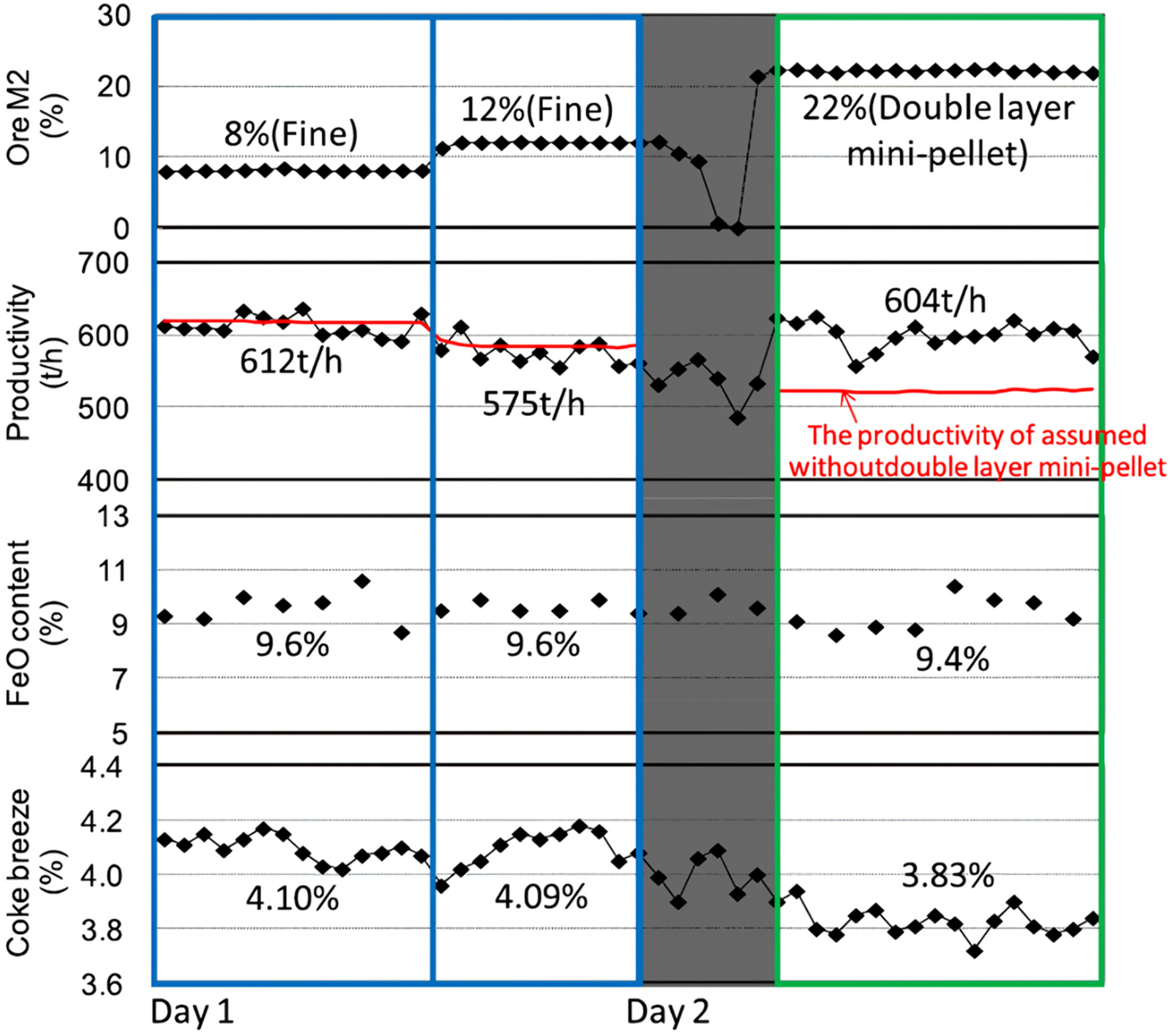
Effect of double-layer mini pellet selective granulation on productivity at Kakogawa sinter plant. 20
Composite agglomeration process
The composite agglomeration process (CAP) is a technique developed by the Baotou Iron and Steel Group (China) to prepare high-grade sinter using 40% magnetite concentrate for blast furnace application.10,111–117 The first industrial installation of this process was in 2008. Figure 24 shows the conceptual illustration of the CAP. 10
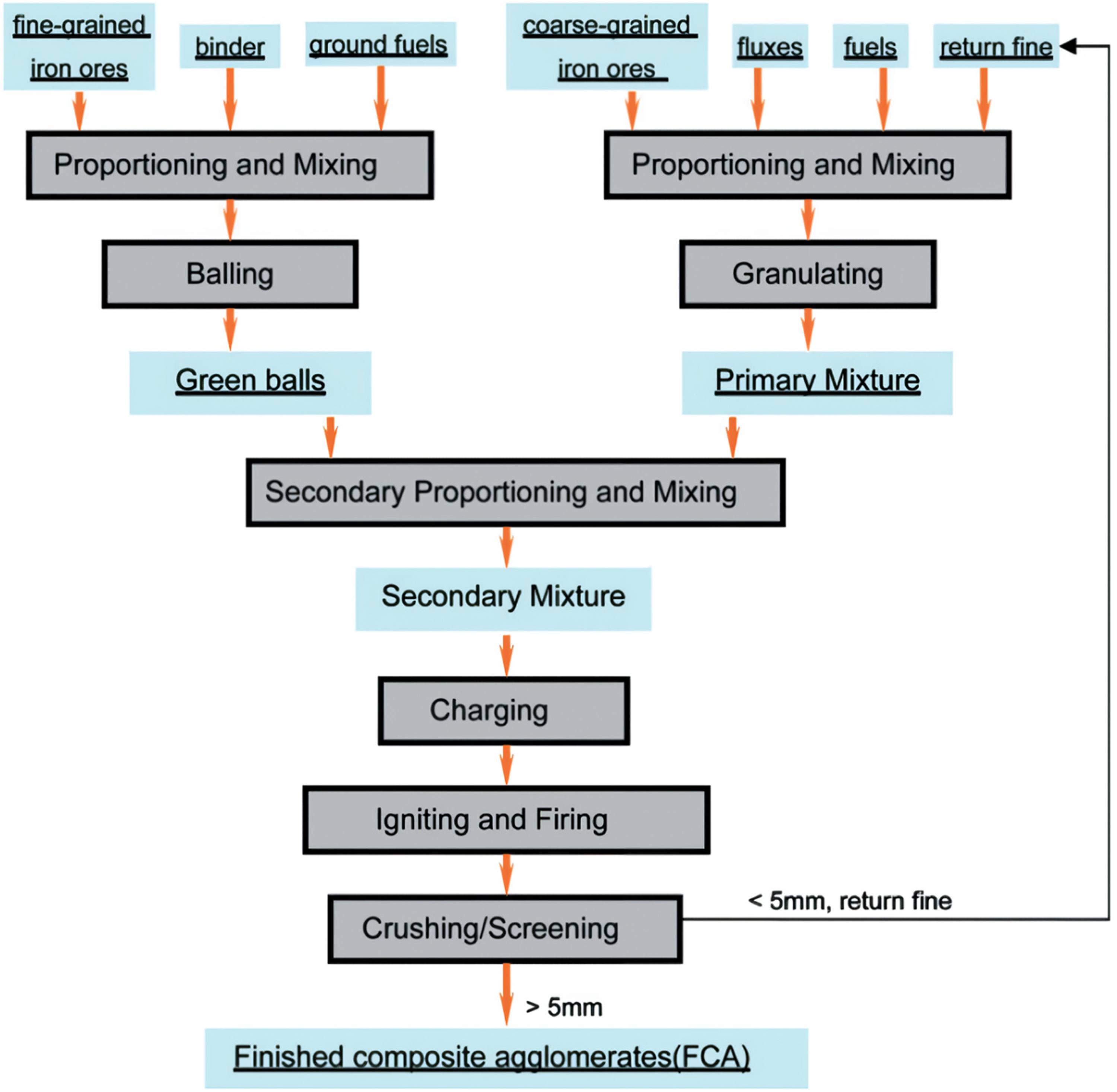
Illustration of composite agglomeration process. 10
In this process, magnetite concentrate, coke breeze and burnt lime are pre-balled to form green acidic pellets (8 to 16 mm particle size), while the coarse iron ore blends, sinter return fines, dolomite, limestone, and burnt lime are granulated in a conventional drum to produce high-basicity matrix granules. The green acidic pellets and high-basicity matrix granules are mixed before charging into the sintering machine. Sinter productivity increases due to an improvement in the FFS. 10 The resulting sinter structure is a high basicity matrix with an embedded acidic pellet presented in Figure 25. 10 An additional advantage of the CAP is the production of sinter in the basicity range of 1.4 to 2.0 with good metallurgical performance. 10
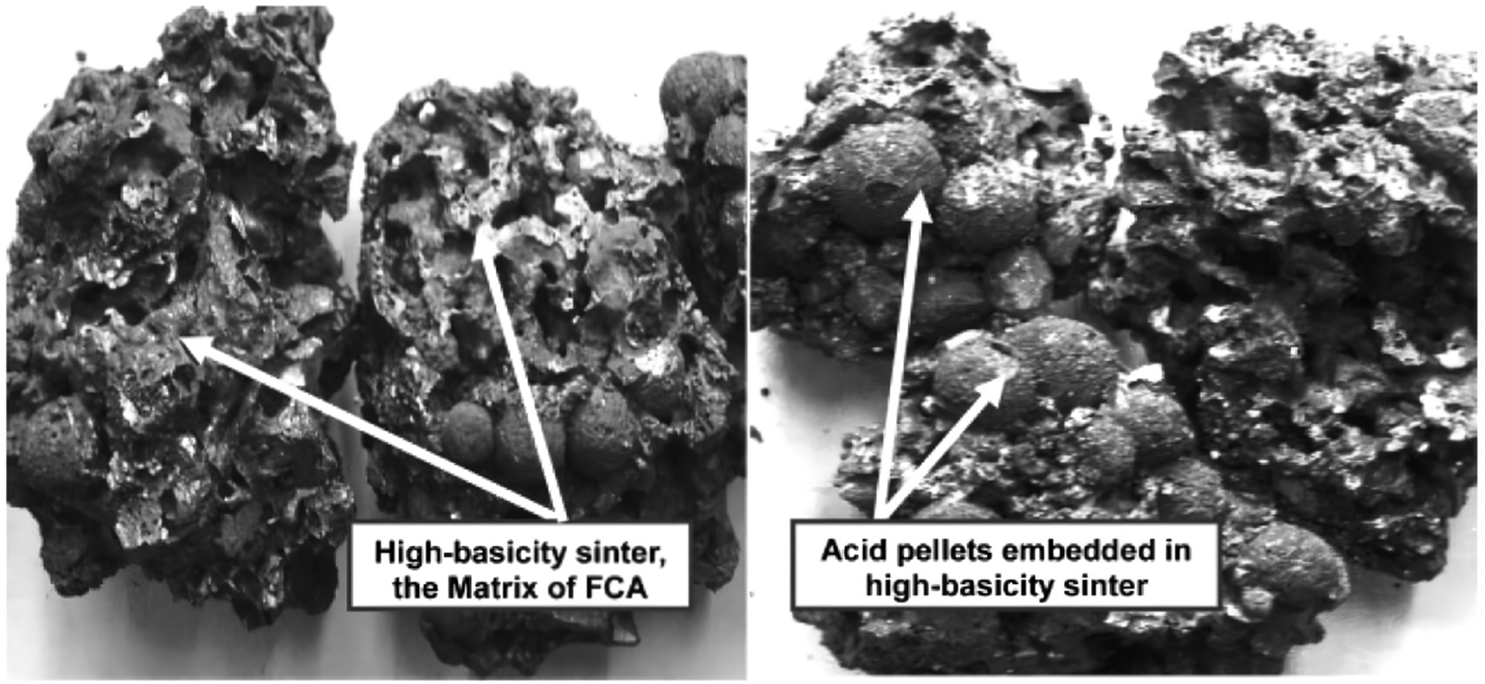
Iron ore sinter product of the composite agglomeration process. 10
Intensive mixing and granulation system
IMGS is another effective method to granulate iron ore blends containing a significant proportion of ultrafine concentrates. The installation of a high-speed intensive mixer before granulation enhances the homogeneity of the raw materials mixture and ensures the effective utilisation of moisture available for granulation.18,32,87,118–127 The sinter raw materials, including coarse, fine, and ultrafine iron ores, additives, solid fuels, return fines, and recycled materials from the steel plant, are continuously fed into a high-speed intensive mixer. In this stage, both macro- and micro-mixing occur ensuring thorough blending of high- and low-density, as well as fine and coarse particles. After mixing, the material is transferred to the granulator, where uniformly dispersed water is applied to the surface of the iron ore particles, allowing fines to bind to the coarse nuclear particles. 18 A layer-by-layer growth aided by the intensive mixing reduced the coalescence of granules, see Figure 26, which improves the granules’ strength and green bed permeability. 118
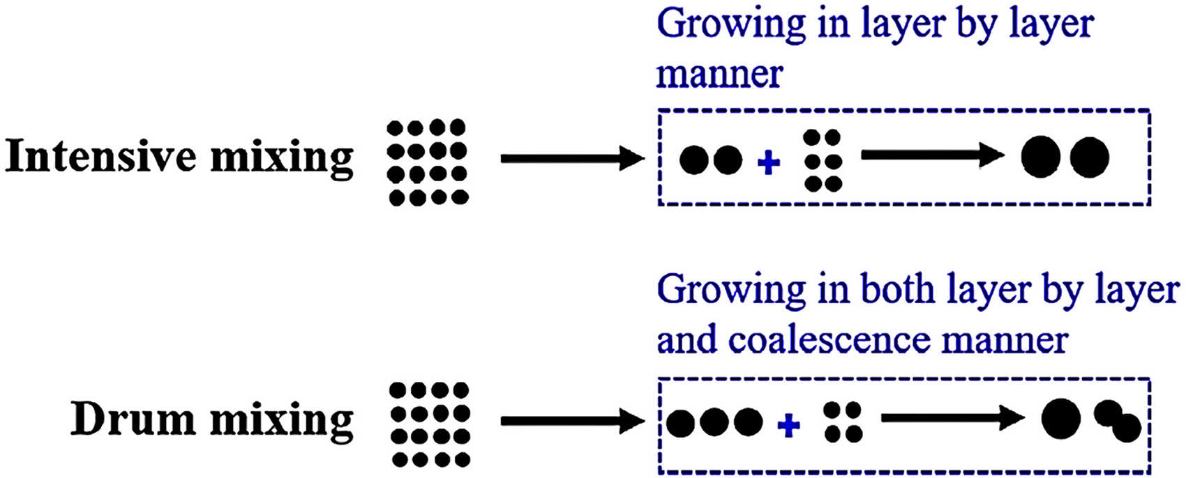
Illustration of the influence of intensive mixing and conventional mixing on granule growth. 118
The flow process of the IMGS developed by Primetals Technologies is presented in Figure 27. 124 It can accommodate up to 80% ultrafine magnetite concentrate to produce high-quality sinter at high productivity levels. 18 Some examples of commercial applications of this type of process are available at Nippon Steel (Japan), 107 Baosteel (China), 118 Ansteel (China), 118 Voest-Alpine Industrieanlagenbau (Austria), 118 ArcelorMittal Gent (Belgium), 125 Companhia Siderúrgica Nacional (Brazil), 118 Usiminas Sinter Plant (Brazil), 123 Dragon Steel Corporation (Taiwan) 126 and National Mineral Development Corporation (India). 17

Process flow of primetals process intensive mixing and granulation system. 124
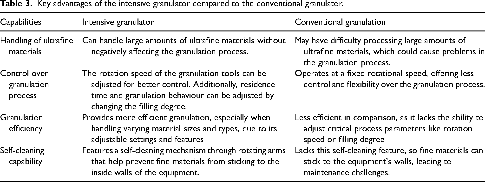
The IMGS utilises an intensive granulator instead of the conventional granulator. The key advantages of the intensive granulator compared to the conventional granulator are outlined in Table 3.18,128
Key advantages of the intensive granulator compared to the conventional granulator.
Primetals Technologies’ IMGS installed at the Dragon Steel Corporation (Taiwan) 126 and National Mineral Development Corporation (India) 17 produce high-quality sinter with production levels of about 1.25 t·m–2·h–1 and 1.29 to 1.61 t·m–2·h–1, respectively. Using this type of process (Eirich mixer installed before the granulation drum), 123 sinter productivity at the Usiminas Sinter Plant (Brazil) increases from 1.3 t·m–2·h–1 (conventional) to 1.4 t·m–2·h–1 due to improvement in the FFS. Key advantages of the Primetals Technologies IMGS are that a blending yard is not required, and it can be installed as a new sinter plant as well as retrofitted within an existing sinter plant of various sizes. 18
Intensive mixer and multiple granulation drum
TISCO (China), with a 450 m2 sinter plant, study a process where an intensive mixer is installed within a series of granulation drums. 127 TISCO uses a high-grade magnetite concentrate (66.9% TFe and 28.6% FeO) with 69.7 mass% in particle size <45μm. 127 A schematic illustration of the system is presented in Figure 28. 127
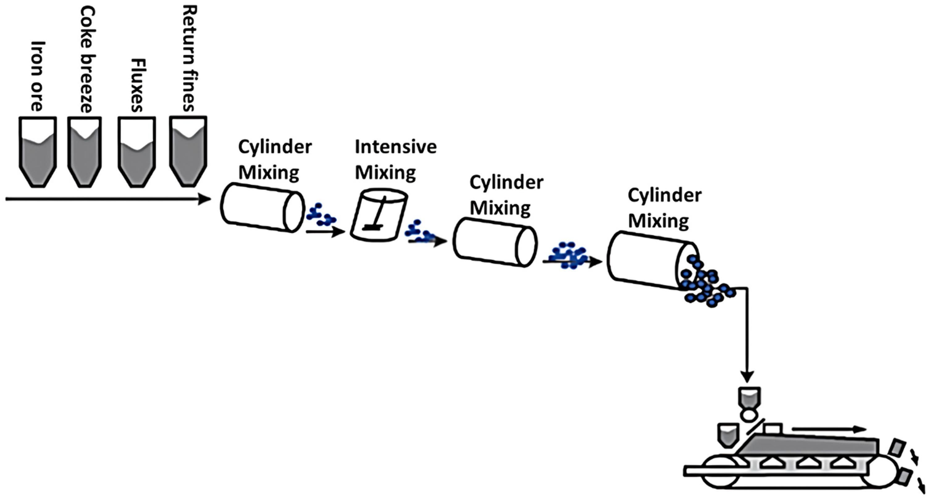
Illustration of intensive mixing and multiple granulation system. 127
A laboratory scale study of this technology found that the binder is uniformly dispersed in the mixture and improves granules’ strength and green bed permeability. Sinter productivity increases due to an improvement in the FFS. 127 There is however no publicly available data to confirm if this process has been employed in a full-scale commercial application at TISCO or any other commercial sinter plants.
New binders: Organic and ore microparticles
Binders are added to sinter raw materials to produce strong granules that would not deform easily in the packed bed.60,65 Ishikawa et al. 60 studied the effect of various binders on sinter productivity and quality and found that burnt lime is the most effective compared to Portland cement, cement clinker and blast furnace cement. Burnt lime facilitates the development of a strong layer bridge between the adhering fines and nuclei particles. During the cold-packed bed preparation stage, burnt lime improves the green bed permeability by inhibiting the deformation and fracture of the granules in the sintering bed.129–132 During the hot-packed bed transformation stage, burnt lime behaves ‘cement-like’ such that its effect is reinforced at high temperatures or at least until a particular temperature to ensure bed stability during sintering. 87 The stability of the sintering bed during drying and calcination improves the flame front speed.130,133 Burnt lime is widely used in commercial sinter plants worldwide,22,60,65,134,135 while hydrated lime is used in most laboratory-scale studies. They both contribute to the calcium component of the sinter.
Organic binders and ore microparticle binders do not alter the chemistry of the iron ore sinter. Additionally, they also reduce the slag content of the ore burden used in ironmaking.9,136 Polyacrylamide (anionic polymer dispersants (APD)), polyvinyl alcohol, and carboxymethylcellulose (anionic cellulose ethers) binders are recommended for iron ore sintering in a study carried out by several European groups consisting of Voestalpine Linz, ArcelorMittal Gent, and Tata Steel. 87 The suitability of these organic binders in sintering is due to their wettability, adhesive force, cohesive force, and thermal stability. 136 Only a small amount, generally less than 0.3 mass%, was recommended for use in sintering. 87 In the European study, the organic binders are specifically used to evaluate the effect of recycled plant dust on the sintering process. 87
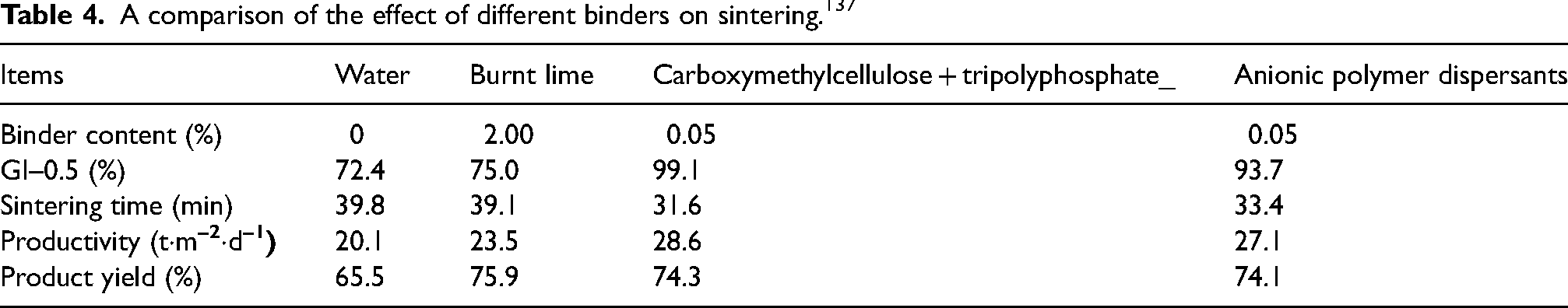
In a sinter pot study conducted by Okada et al., 137 it was found that the addition of a small dosage of organic binders (only 0.05%) significantly enhanced sintering productivity, better than traditional burnt lime. The study demonstrated that organic binders, even in relatively low quantities, enhance the efficiency of the sintering process more effectively than the traditional burnt lime, which has long been the standard binder in sintering operations. A comparison of the performance of organic binders versus burnt lime is provided in Table 4.
A comparison of the effect of different binders on sintering. 137
Selecting the appropriate organic binder for iron ore sintering requires careful consideration of both performance and cost factors.136,138 The selected organic binder is expected to:
enhance granule strength, size distribution, and stability during handling and in the sintering bed. avoid the introduction of harmful elements, such as alkalis, that could negatively impact sinter quality or blast furnace performance. Additionally, it should not reduce iron content or increase impurities, and any potential contamination from the binder's production process must be evaluated. cost-effective for sinter plant operations, ensuring that it does not undermine profitability. compatible with existing sintering equipment, and any necessary upgrades or modifications should be carefully weighed against the benefits of using the binder to avoid unnecessary capital expenses while maintaining productivity.
Commercial application of organic and or microparticle binders
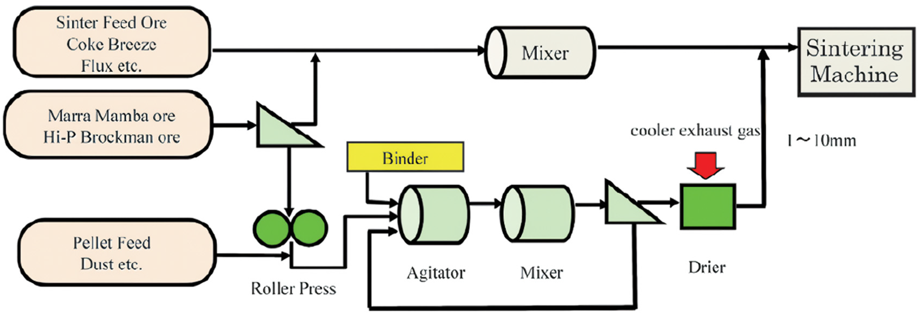
The semi-pellet expansion (SPEx II, a combination of APD and iron ore microparticle) and iron ore microparticle binder are technologies developed by Nippon Steel and installed at the Yawata Works and Wakayama Works, respectively.9,106,137,139–141 The process flow diagram of the SPEx II and iron ore microparticle binder technologies are given in Figures 29 and 30, respectively.
In SPEx II, Marra Mamba or high-phosphorus Brockman iron ore is crushed to <10 µm size using a roller press. The proportion of microparticles used in the sintering process is not stated. APD is used to disperse the ore microparticles (<10 µm) in water to form a slurry that strengthens the contact between the nuclei and fine particles or between the fine particles, increasing the granules’ strength. Only a small proportion (about 0.05 mass%) of APD was required in the process.
140
The iron ore microparticle binder forms strong granules without the use of expensive dispersants, such as APD.
139
In this process, low-grade goethite iron ore, representing 0.5 mass% of the sinter blend, is crushed to <10 μm size using a vertical wet ball mill.
9
The slurry of ultrafine particles is fed into an intensive mixer containing concentrates and other sinter raw materials. After mixing, it is fed into a pan-pelletiser to produce granules. The ultrafine particles fill the voids between the ore grains to improve the granule strength. The strengthened granules enhance the permeability of the sintering bed and consequently sinter productivity increases due to an improvement in the FFS. Figure 31 shows the operational data at the Nippon Steel Wakayama No. 5 sinter machine.
9
Sinter productivity improves by 2.4% while using 13.3 mass% of ultrafine iron ore particles.9,139
Process flow sheet for semi-pellet expansion (SPEx II) at the NSSMS Yawata Works (Tobata No. 3) sinter machine. 106
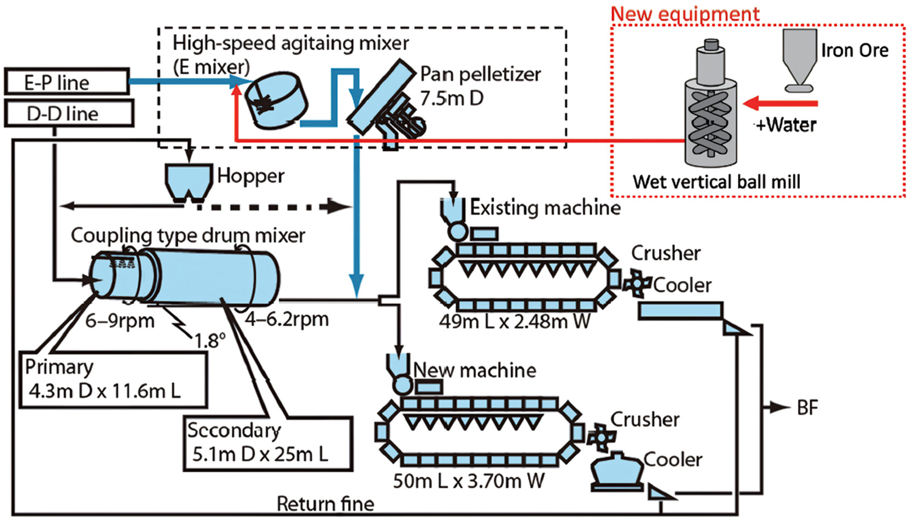
Process flow sheet for ore micro-particle binder at the Nippon Steel Wakayama Works. 9
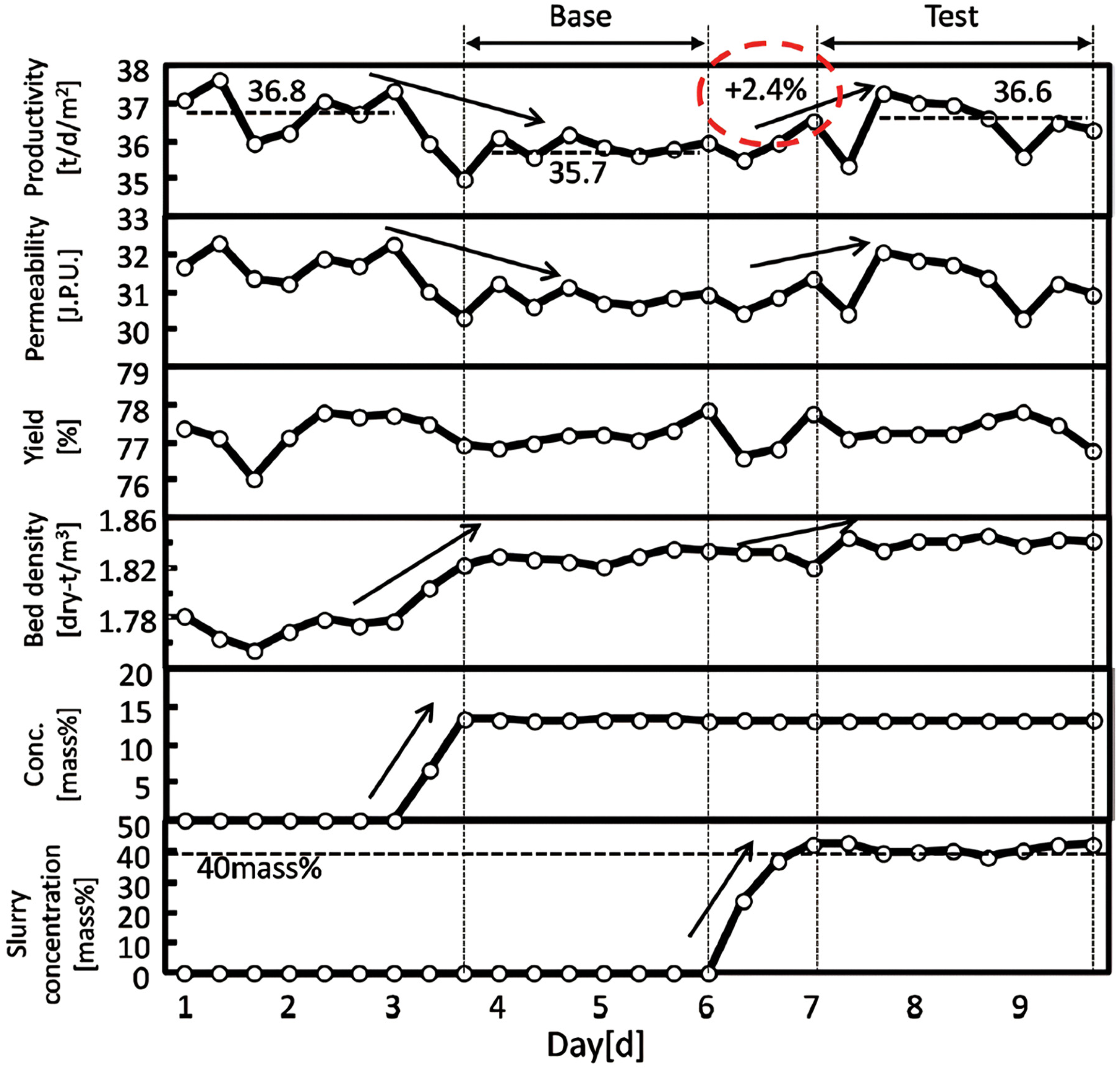
Effect of iron ore microparticle binder on sintering operation at Nippon Steel Wakayama No. 5 sinter machine. 9
An improvement in the compressive strength of granules (both in wet and dried conditions) using these technologies is related to the ore microparticle concentration, such that an increase in the proportions of microparticles increases the compressive strength of the granules. 141 The behaviour of ore microparticles during granulation 141 and the cohesive layer structure of a granule showing ore microparticles acting as a binder 139 are presented in Figures 32 and 33, respectively.
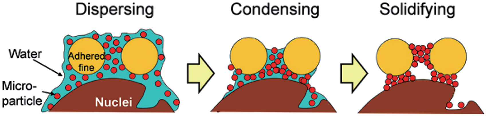
Behaviour of iron ore microparticle during granulation. 141
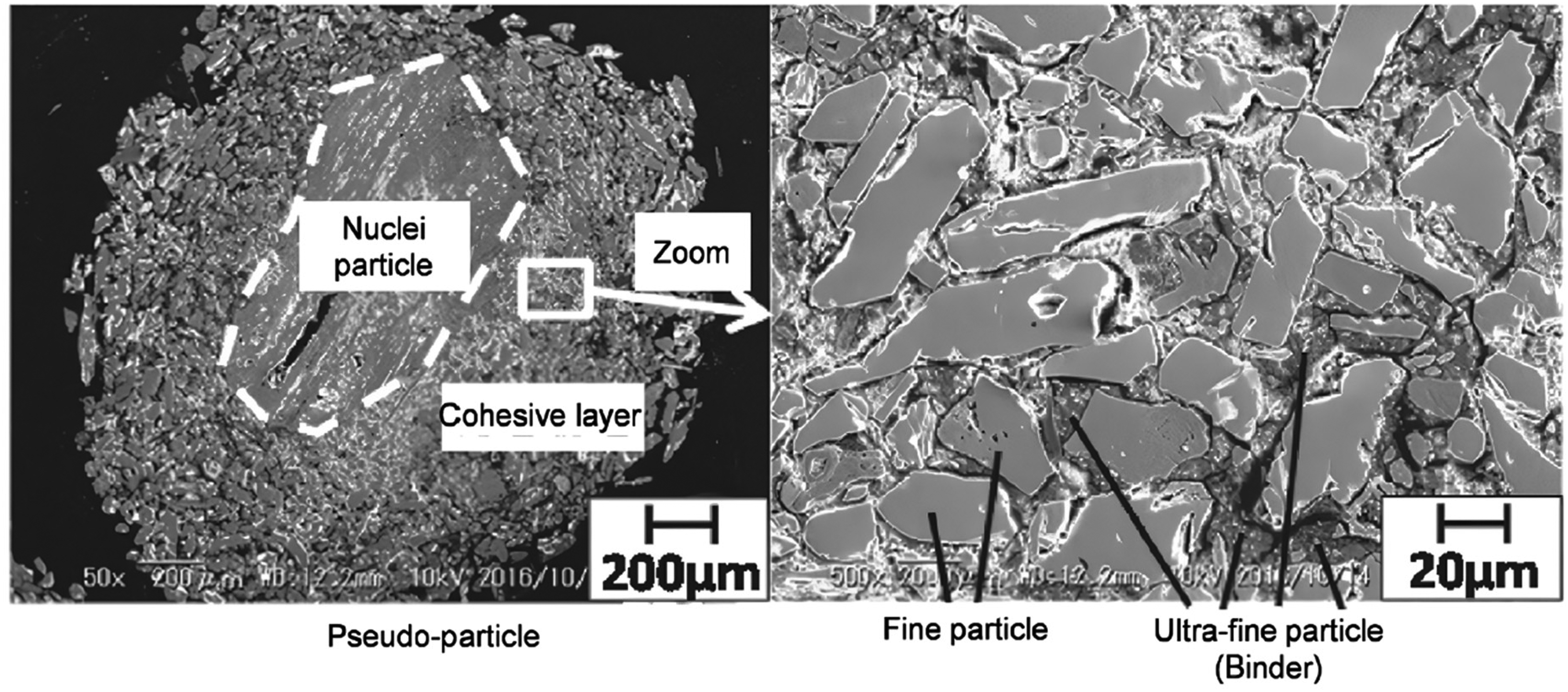
Cohesive layer structure of a granule with iron ore microparticles acting as a binder. 139
Table 5 provides an overview of several commercially applied technologies for raw material preparation, emphasising their capacity to integrate high proportions of concentrates and their impact on sintering operations. It also includes, where available, data on the specific proportions of concentrates used in sinter production, offering a more detailed understanding of the operational dynamics. Among these technologies, IMGSs developed by Primetals Technologies stand out as particularly effective. These systems can incorporate up to 80% ultrafine magnetite concentrate into a sinter blend, demonstrating their ability to accommodate high levels of concentrates without compromising the quality or efficiency of the sintering process. By integrating large proportions of ore concentrates, these systems support resource optimisation and contribute to the overall sustainability of the production process. Similarly, Nippon Steel's iron ore microparticle binder technology plays a pivotal role in enhancing the granulation process. The binder aids in the formation of strong granules and enhances bed permeability. The ability to process high proportions of concentrates while maintaining the green and sinter bed permeability, directly contributes to operational efficiency and sustainability in the sintering process. These technologies (intensive mixing and granulation and iron ore microparticle binder) represent a significant advancement in the raw material preparation stage of sinter production.
Capabilities of raw material preparation technologies to accommodate ultrafine concentrates.
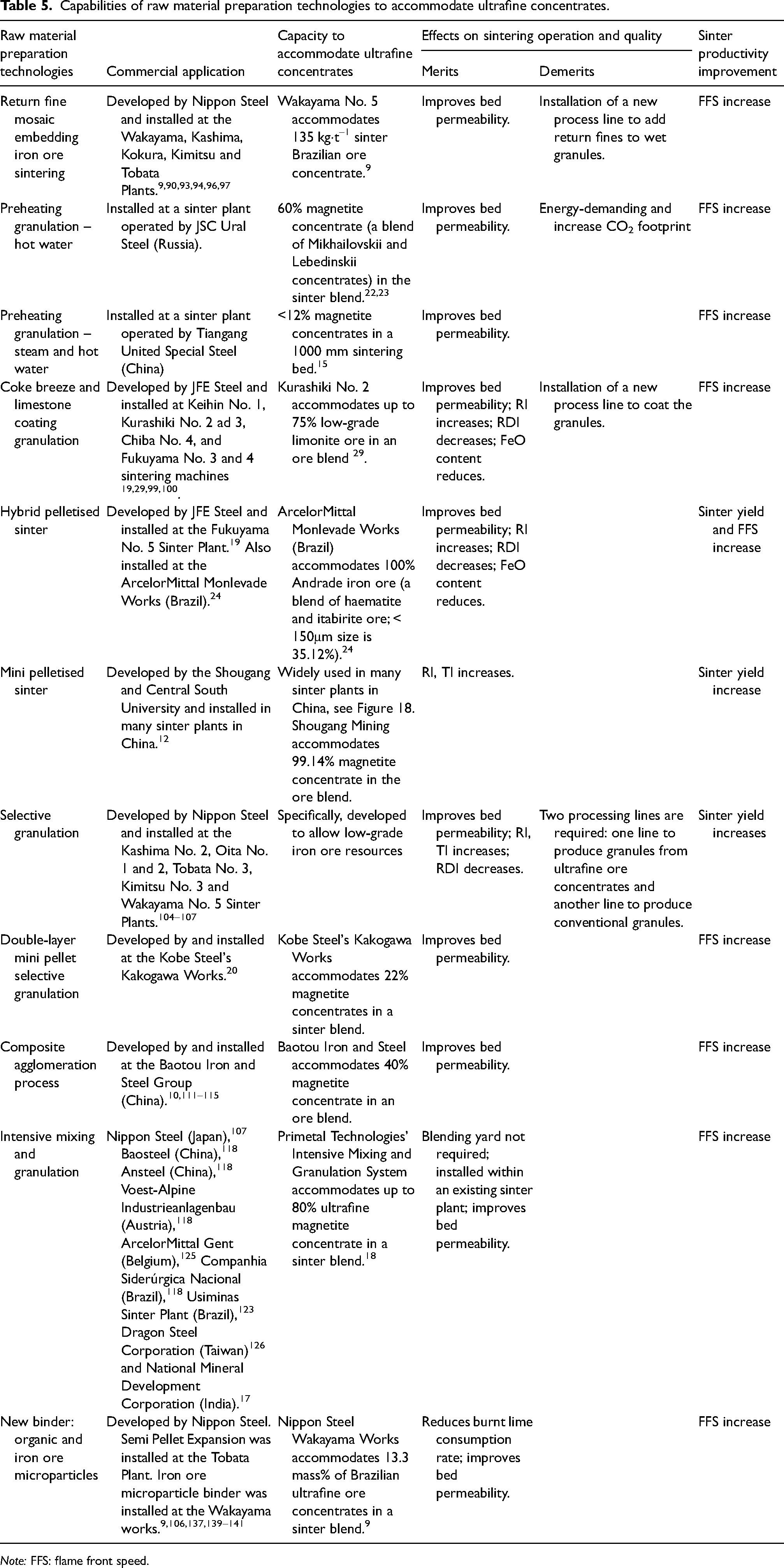
Note: FFS: flame front speed.
Hot-packed bed sintering
The quality of the granules produced through raw material preparation technologies affects their ability to be evenly distributed across the sintering bed. Using appropriate techniques for charging granules into the sintering bed facilitate desirable particle segregation to improve green bed permeability. The conventional sintering process uses a rod or chute feeder; however, some commercial sinter plants have installed the magnetic brake feeder,52–54 segregation slit wire,24,142 and intensified sifting feeder142,143 technologies to improve bed permeability. The magnetic brake feeder has been reported to enhance particle segregation of granules containing return fines, mill scale, and ore concentrates due to their magnetite properties. 53 This technology has been installed at the JFE Sinter Plants (Kurashiki No. 3, Mizushima No. 3 and Keihin No. 1), and on the three sinter strands of Baoshan Iron and Steel.52–54 It can be retrofitted to an existing sinter plant with the added advantages that the granules do not stick to the charging apparatus and a separate power source is not required as it uses permanent magnets. 12
To meet the continuous demand for iron and steel products, a thick or deep bed sintering is one approach that can be conveniently utilised in the ironmaking industries to increase sinter productivity. A thick bed sintering is practised for more sustainable ironmaking operations. Since 2000, the average thickness of the sintering bed has increased drastically. Most sinter plants in Asia now operate at bed thickness >800 mm, specifically, POSCO Gwangyang at 830 mm, Shougang Jingtang at 860 mm,88,89 Ma Steel at 900 mm 135 and Tiangang United Special Steel at 1000 mm. 15 An increase in sintering bed height is related to a significant reduction in the total energy consumption in the sinter plant.15,144
As the thickness of the sintering bed increases, green bed permeability as well as flame front permeability deteriorates.135,144–146 This generally leads to an uneven distribution of heat in the sintering bed. Several commercial sinter plants have installed unconventional technologies such as secondary-fuel injection technology for energy reduction (Super-SINTER and Super-SINTER OXY), stand support sintering and double-layer sintering to address the challenge associated with the uneven distribution of heat in the sintering bed. A brief description of these technologies is given below.
Secondary-fuel injection technology for energy reduction (Super-SINTER and Super-SINTER OXY)
The Super-SINTER and Super-SINTER OXY are technologies developed by JFE.147–151 Hydrogen-based fuel (Super-SINTER) or a combination of hydrogen-based fuel and oxygen (Super-SINTER OXY) is injected from the top of the sintering bed as a partial substitute for coke to compensate for the lack of sufficient heat in the upper layer of the sintering bed.149,152
Super-SINTER technology has been installed at the East Japan Works (Keihin No. 1 in 2009) and West Japan Works (Kurashiki District in 2010).147,148,150 A reduction in the CO2 emission levels was achieved by a maximum of approximately 60,000 tons per year at the Keihin No. 1 sinter plant.149–151 Super-SINTER OXY technology, thought to be an improvement on the Super-SINTER technology, has been installed at the East Japan Works (Chiba No. 4 in 2014).147,148,150 A schematic of the Super-SINTER OXY technology is presented in Figure 34.
147
In the ignition hood, LNG (CH4/C2H6/C3H8 = 89/5/6 vol%) and oxygen are injected from nozzles oriented perpendicular to the strand direction and drawn into the suction air stream.
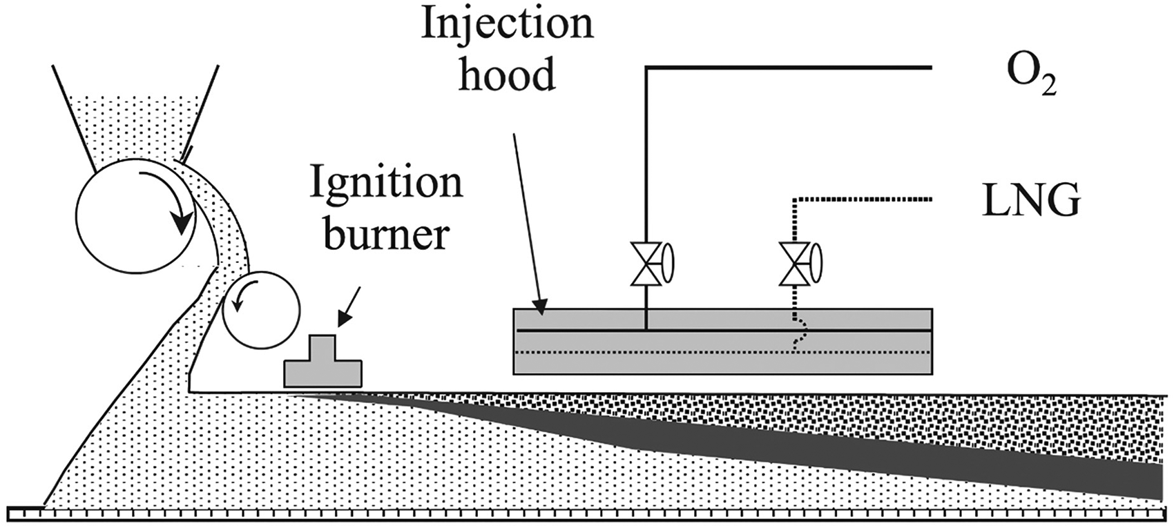
Illustration of Super-SINTER OXY technology installed at JFE Steel, East Japan Works Chiba No. 4 sinter plant. 147
The main advantage of Super-SINTER OXY over Super-SINTER is the availability of more oxygen for the sintering process. 147 Oxygen enrichment in the top layer of the sintering bed improves sinter yield, shatter index, and the FFS. 153 Operational data at Chiba No. 4 when oxygen injection increases from 21 volume% to 27 volume% at a constant LNG injection (0.4 volume%), the tumble strength increases (from 63.1% to 64.3%), and the burnt lime consumption rate decreases (from 10 kg·t–1 sinter to 8 kg·t–1 sinter). 149
Stand support sintering
Nippon Steel developed the stand support sintering technology, as shown in Figure 35, to withstand the weight of the upper layer sinter cake and improve the permeability of the sintering bed.34,35 It was installed at the four sintering machines at Nippon Steel's Kimitsu and Oita Works. It was installed at Kimitsu No. 1 (with a grate area of 183 m2 in 1996), Kimitsu No. 2 (with a grate area of 280 m2 in 1997), Kimitsu No. 3 (with a grate area of 500 m2 in 1997), and Oita No. 2 (with a grate area of 660 m2 in 2004). 35
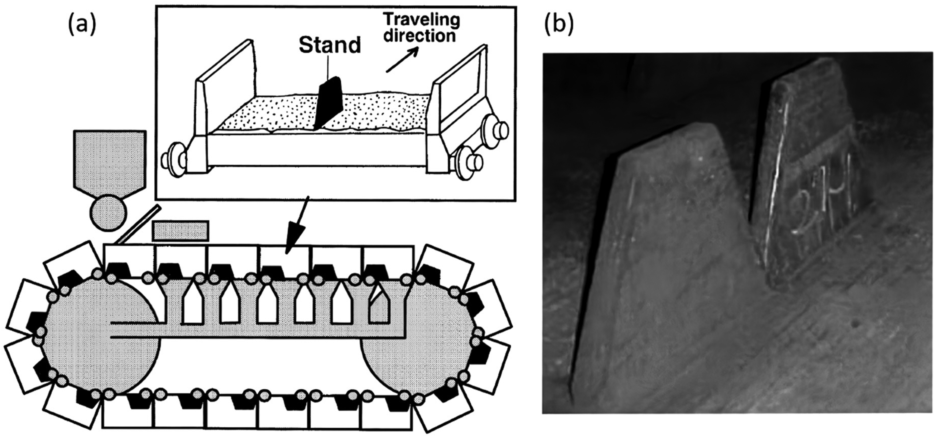
Reportedly, the optimal value of sinter productivity is achieved when the stand support is located at about 50% of the bed height.34,144,154 The stand support facilitates a large-sized pore network in the middle and lower layers of the sintering bed. 34 Nippon Steel Kimitsu Steel Works operational data shows that the FFS and sinter yield improves, leading to about 11% increase in sinter productivity, from 1.58 t·m–2·h–1 to 1.75 t·m–2·h–1.34,35 Furthermore, the coke consumption and burnt lime consumption rates are reduced by 10% (from 55 kg·t–1 sinter to 50 kg·t–1 sinter) and 14% (from 18.3 kg·t–1 sinter to 15.8 kg·t–1 sinter), respectively.34,35
Double-layer sintering
Recently, Ansteel Group (China) has carried out industrial experiments15,16 and mathematical simulation 155 of the double-layer sintering in a 1000 mm depth bed to meet the requirements of its ironmaking process while using 70 mass% magnetite concentrate in the ore blend. The technology is a two-stage simultaneous charging and ignition on a single sintering machine, as presented in Figure 36. 156 The two-stage simultaneous charging and ignition of the upper and lower layers of the sintering bed shorten the sintering time significantly, resulting in an improvement in sinter productivity. 156 However, the impact of this technology on coke consumption rate as well as CO2 emission levels was not reported. There is however no publicly available data to confirm if this process has been employed in a full-scale commercial application at Ansteel Group or any other commercial sinter plants.
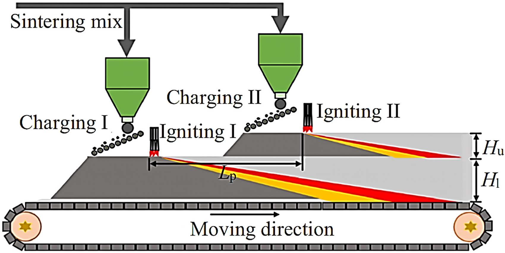
Illustration of the double-layer sintering technology. Lp is the pre-sintering interval; Hu and Hl are the bed height of the upper and lower layers, respectively. 156
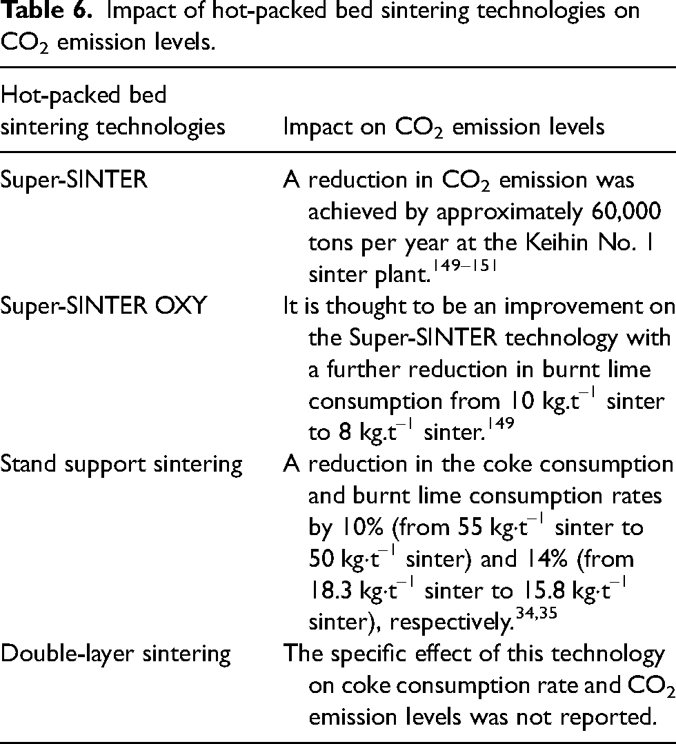
Based on the availability of data, Table 6 highlights the impact of the hot-packed bed sintering technologies on CO2 emission levels. Also, leveraging on the benefits of each of the technologies, it can be suggested that a combination of Super-SINTER OXY and stand support sintering can be retrofitted to a thick or deep sintering bed to sustain and stabilise the ironmaking process, as well as achieve a significant reduction in CO2 emission levels.
Impact of hot-packed bed sintering technologies on CO2 emission levels.
Proposed recommendations for a sustainable sinter plant
Figure 37 shows a conceptual illustration of a sinter plant that is thought to have the capability to accommodate a significant proportion of ore concentrates in the sinter blend, maintain bed permeability and stability, sustain productivity levels, produce high-grade sinter, and reduce CO2 emission levels. This illustration is based on the key highlights of the existing technologies discussed in the raw material preparation and hot-packed bed sintering sections.
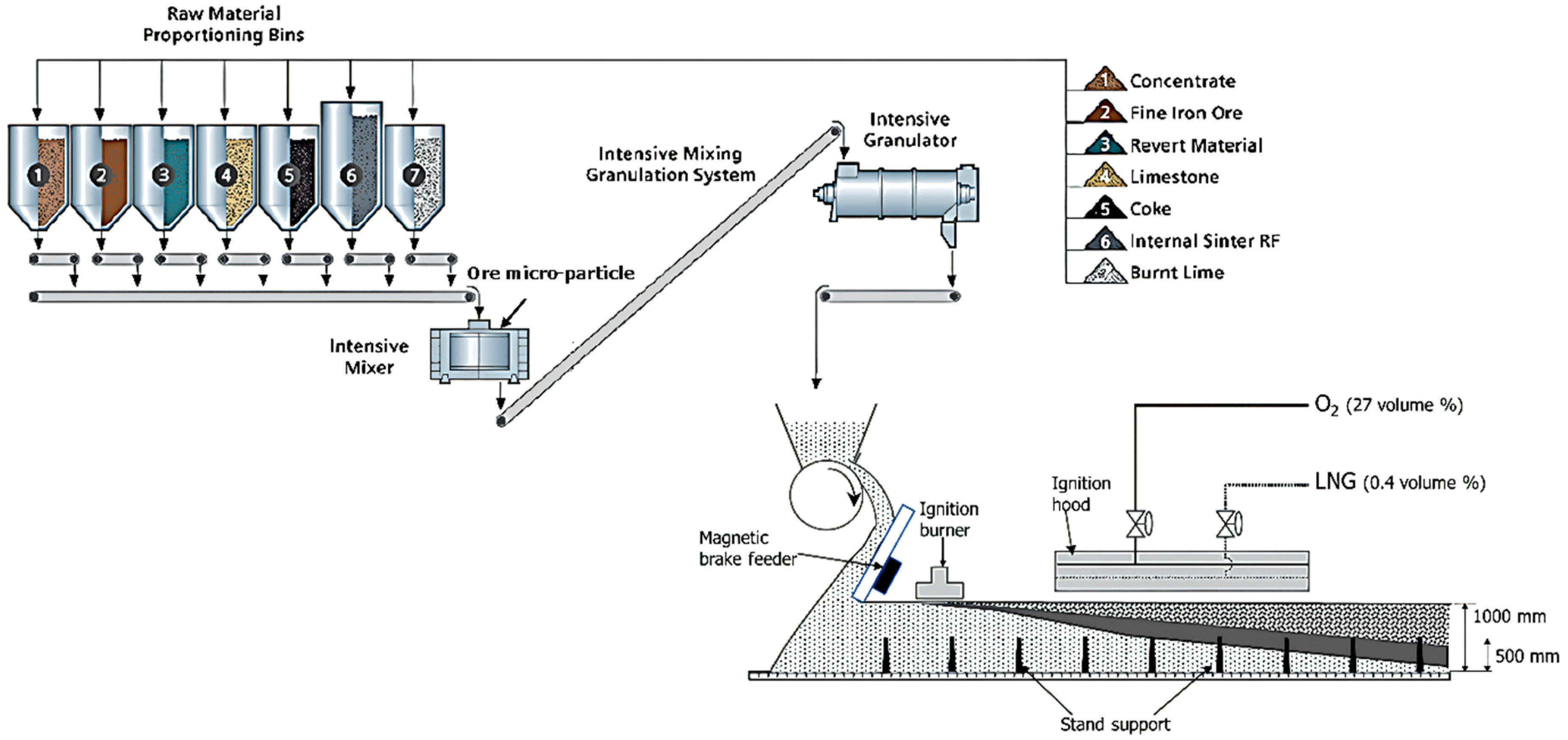
Conceptual illustration of a proposed sinter plant to accommodate large proportions of concentrates as well as reduce CO2 footprint.
A combination of the existing advanced technologies, including IMGSs, ore microparticle binders, magnetic brake feeders, Super-SINTER OXY, and stand support systems, offers a sustainable solution for the ironmaking industry as it adapts to the ongoing changes in ore resources. Among all raw material preparation technologies, IMGSs are considered to have a significant flexibility advantage, with the capability to accommodate up to 80% magnetite concentrates. These systems can either be installed in new sinter plants or retrofitted into existing ones, making them adaptable to different operational needs. The inclusion of an iron ore microparticle binder in the intensive mixing and granulation process can further optimise the system by reducing the consumption of burnt lime, which, in turn, leads to a decrease in CO2 emissions. Additionally, due to the magnetic properties of granules containing substantial amounts of magnetite concentrates, the magnetic brake feeder is suitable to improve particle segregation and ensure the proper distribution of coke particles within the sintering bed. This technology is also flexible and capable of being retrofitted into sinter plants of various sizes. The Super-SINTER OXY technology, an enhancement of the Super-SINTER technology, has been demonstrated to reduce CO2 emissions by approximately 60,000 tons annually. In addition to its environmental benefits, this technology lowers burnt lime consumption from 10 kg·t–1 sinter to 8 kg·t–1 sinter, further contributing to sustainability goals. The stand support sintering system enhances key aspects of the sintering process. It improves the permeability of the green bed and the flame front, as well as gas flow distribution, which are critical for efficient sintering. Likewise, it reduces coke consumption by about 10%, further decreasing CO2 emissions. Collectively, these technologies provide a comprehensive approach to optimising ironmaking processes, making it sustainable.
Additionally, the proposed processing route for a sustainable sinter plant is influenced by the inherent properties and specific characteristics of the iron ore concentrate, which can vary significantly around the world. These variations, which include differences in composition, mineralogy, and physical properties, are critical factors that directly impact both the sustainability and operational efficiency of the sinter plant. It is to be noted that the acceptance of the proposed sinter plant configuration is dependent on compliance with the intellectual property rights of the individual technology as well as techno-commercial feasibility at the ironmakers’ end. It is well documented that each of the technologies in the proposed sustainable sinter plant configuration has been used in commercial applications and adjudged to be effective in terms of productivity and process efficiency. It is envisaged that this suggested sinter plant configuration will be of interest to ironmaking industries to warrant a sustainable operation.
Conclusions
This study presents a comprehensive overview of the sintering technologies currently available for utilising high-grade iron ore concentrates in sinter production to enhance the quality of the sinter and reduce CO2 emissions. It is noted that effective countermeasures, including raw material preparation, granule charging, and hot-packed bed sintering technologies, have been developed to adapt to the evolving nature of contemporary iron ore resources. These technologies, however, do not operate in isolation. Instead, they are interconnected, working in synergy and dependent on the intrinsic nature and particular characteristics of the iron ore concentrate, to meet the economic and environmental criteria necessary for the sustainable operation of the ironmaking industry.
To support a sustainable ironmaking process, this study proposes a model sinter plant. This model integrates advanced systems, such as intensive mixing and granulation units, ore microparticle binders, magnetic brake feeders, Super-SINTER OXY technology, and stand support mechanisms, all designed to adjust to the continual variations in sinter feedstock grade. These technologies collectively aim to increase the proportion of ultrafine ore concentrates in the feedstock, enhance green bed and sinter bed permeabilities, optimise sinter quality and reduce environmental impact, aligning with the industry's sustainability goals.
For a more thorough and ongoing evaluation of sintering technologies, it is essential to compile a broader range of operational data from commercially implemented technologies beyond those covered in this study. This data collection should include a variety of operational settings to gain a broader understanding of the effectiveness of these technologies under different conditions. In addition, fundamental research on new technologies conducted at laboratory and pilot plant scales is key to better understand of their impact on sinter productivity and process efficiency. Nonetheless, it is important to acknowledge that the adoption of new technologies ultimately remains at the discretion of the industry. Furthermore, operational data from plants may be subject to confidentiality agreements and, therefore, may not be readily accessible in the public domain.
Footnotes
Declaration of conflicting interests
The authors declared no potential conflicts of interest with respect to the research, authorship, and/or publication of this article.
Funding
The authors disclosed receipt of the following financial support for the research, authorship, and/or publication of this article: This work was supported by the Australian Research Council (ARC) through the Industrial Transformation Research Hubs Scheme (Grant No. IH200100005).