
Abstract
Objective
To propose and validate a method for standardizing and printing cephalograms acquired from different imaging systems.
Methods
Validation of the proposed method was done using digital cephalograms, cone beam computed tomography (CBCT)-derived cephalograms, and direct measurements obtained from 3 dry human skulls. Each cephalogram was analyzed as-received and after standardization, using both manual and digital methods. 3-dimensional (3D) measurements were also computed from the CBCT images. After adequate blinding, 2 observers independently carried out all these measurements at 2 different times. Finally, the different cephalometric measurements of each skull were compared with the corresponding direct measurements (gold standard).
Results
The as-received digital cephalogram showed an inherent magnification of 33%, as determined from the calibration ruler. Compared to direct skull measurements, the as-received conventional and CBCT-derived cephalograms printed without standardization showed a reduction in measures of around 14% and 28%, respectively, whereas measurements obtained from cephalograms, which were standardized and printed by the proposed method, were comparable to direct measurements.
Conclusions
The findings of the validation study demonstrate the robustness of the proposed method in standardizing different cephalograms before printing.
Introduction
Magnification is a consequence of any 2-dimensional (2D) radiographic technique because of the divergence pattern of the x-ray beam originating from the source and hitting the target which at a certain distance from the source and film. 1 This radiographic magnification increases as the target-to-film distance increases.2, 3 The angular measurements and proportions remain unaffected because of the uniform magnification of all structures, while linear measures can prove to be inaccurate. 4 6 Moreover, the values obtained from magnified radiographs cannot be compared with norms, and performing superimposition of serial radiographs is not viable. 7
It is not unusual to encounter situations where the same patient’s cephalograms acquired from different machines may not have the same magnification factor. Even images obtained with devices of the same manufacturer may have a varying magnification rate of 0.6% to 2.3%. 5 When the radiographic magnification level of 5 major longitudinal cephalometric databases was compared, a significant variation in magnification levels was observed. 6 Hence, it was suggested that instead of using an arbitrary standardized enlargement method, radiographs obtained from different sources be corrected to their true size before comparisons. 6
Apart from the image acquisition, a significant magnification component is added when printing the radiographs. So far, academicians and researchers have preferred manual tracing, which is considered a gold standard method. Many academic institutions worldwide make it obligatory for residents to undergo training in manual tracing before using digital applications. It is impractical to print images in true size unless the film size matches the image size. If the film size is smaller than the original image size, the image will be altered to fit the paper or the portion outside the print area will be cut. Few software allow the automatic magnification correction of cephalometric images before printing. However, this function does not exist in many old software applications. Additionally, printed historical radiographs may have magnification factors that must be corrected before manual tracing.
Various methods for the standardization of posteroanterior cephalograms have been reported in the literature.8, 9 However, to our knowledge, no prior studies have documented the method for standardizing and true size printing cephalograms acquired from different sources such as traditional cephalostat and 3D-imaging systems such as CBCT, computed tomography (CT), and magnietic resonance imaging (MRI). Therefore, the objective of this study was to propose a method for the following”
Standardizing and printing cephalograms obtained from different imaging systems such as conventional, digital cephalogram, and derived cephalograms. Validating the proposed methods using conventional/digital and CBCT-derived cephalograms
Materials and Methods
Skull Preparation and Direct Measurements
The study was conducted on 3 dry human skulls having good symmetry, properly articulated mandible, good posterior intercuspation, and split in the midsagittal plane. The approval of the institutional ethics committee was obtained before starting the study. 6 midsagittal skeletal landmarks were used to perform 10 linear measurements. To avoid landmark plotting error, radiopaque markers (Gutta-percha) of the size 1 mm were glued to the landmarks using cyanoacrylate adhesive. Direct measurements were made on the skull using a digital Vernier calliper (Aerospace-150 mm) having a precision of 0.01 mm.
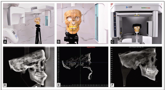
Obtaining 2D Digital and CBCT-derived Lateral Cephalograms
The dry skull was oriented in the cephalostat with the Frankfort Horizontal plane parallel to the floor and the midsagittal plane perpendicular to it (Figure 1). All 2D digital cephalograms were acquired using the NewTom™ Giano 2D imaging system (Aperio, Sarasota, FL, USA) and CBCT scans were acquired using i-CAT™ Next Generation scanner (Imaging Science International, Inc., Hatfield, PA, USA) with the same exposure parameters. The 3D digital imaging and communications in medicine (DICOM) data was loaded into Dolphin™ 3D (Version 11.95, Dolphin Imaging & Management Solutions, Chatsworth, Calif). The images were reoriented in a standardized position, and a lateral cephalogram was generated by the orthogonal projection technique with 0% magnification. All the cephalograms were printed as-received, without any adjustments. Using the proposed method, the image was standardized and then printed.
a) Validation Study; b) Positioning of the Skull in Cephalostat; c) Positioning of the Skull in CBCT Scanner; d) As-received Digital Cephalogram; e) MPR View of the Skull; f) CBCT Derived Cephalogram.
Performing Measurements on 2D Digital and CBCT-Derived Lateral Cephalograms
The 2D digital and CBCT-derived lateral cephalograms were imported into an open-source image analysis software ImageJ (Mac OS version 1.52q, US National Institutes of Health, Bethesda, MD, USA). The calibration was done using the radiopaque ruler present in the cephalograms. The 2D coordinates (x, y) were obtained for all 6 midsagittal landmarks. Similarly, the 3-dimensional (3D) measurements in multiplanar reconstructed (MPR) CBCT images were performed using Dolphin 3D software. The 6 midsagittal landmarks were plotted, and the corresponding x, y, and z coordinates were generated for each landmark. The linear distances between the 2 landmarks in 2D and 3D radiographs were computed (Figure 2).
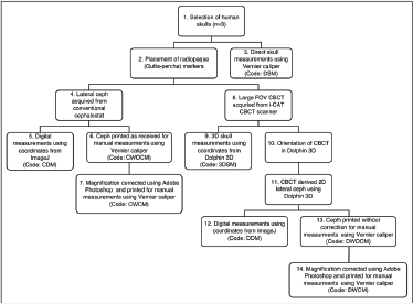
Flowchart Showing the Sequence of the Process Followed in the Validation Study.
Technical Note on Standardization of Cephalograms
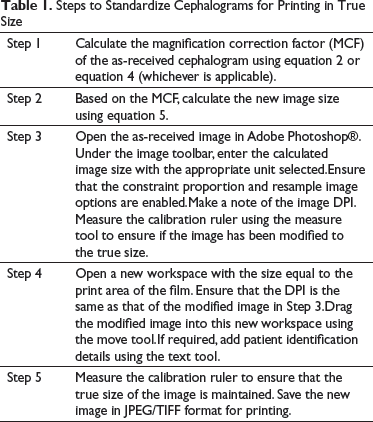
Steps to Standardize Cephalograms for Printing in True Size
Theoretically, the magnification of the cephalogram can be calculated by the ratio of the distance between the x-ray source and the film/detector divided by the distance between the x-ray source and the patient’s midsagittal plane. The percent magnification can be calculated using the following formula:

For example, if the distance between the x-ray source and the midsagittal plane of the subject is 1524 mm and the distance between the subject’s midsagittal plane to the film is 150 mm, using equation 1, the magnification will be 9.84%
The MCF can be calculated using the following formula

For the given example, using equation 2, the MCF will be 0.9104
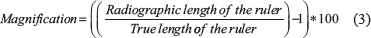
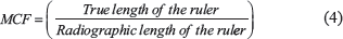
If a calibration ruler is present in the radiograph and the true length of the ruler is known, then the magnification can be calculated using the following:
For example, if the ruler length in the radiographic image is 43.94 mm and the original ruler length is 40 mm, the image is said to be magnified by 9.8% (using equation 3), and the MCF (using equation 4) will be 0.91

For example, if the original image size is 271 X 260 mm and MCF is 0.91, then by using equation 5, the new image size would be 246.61 mm in width (271 X 0.91 = 246.61) and 236.6 mm in height width (260 X 0.91 = 236.6). This new image size is the true size of the object.
Standardization of Cephalogram Using Adobe Photoshop. a) As-Received Digital Cephalogram Showing a Magnification of 33.5% (Distance of Radio-opaque Marker Measured as 60.1 mm Instead of the True Distance of 45 mm) b) After Correction of Magnification, the Distance Between Radiopaque Marker Showed 45 mm, And the Image Size was Corrected According to Film Size (188 X 243 mm and 150 dpi).
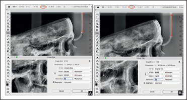
While printing this image, care should be taken to match the image size with the film size. For example, when an image of size 246.6 × 236.6 mm (9.7 × 9.3 inches) is printed using a 203 × 254 mm (8 × 10 inches) sized film, it will not provide a true size image. Another important consideration should be given to the size of the print area. The film's size used in this study was 203 × 254 mm, whereas the print area was only about 188 × 243 mm. So, the image size has to be adjusted as per the print area (Figure 3).
Steps to Standardize Cephalograms for Printing in True Size
Method to Print Any 3D-derived Cephalograms
The size and resolution of the 3D-derived cephalograms may not be the same as conventional or digital cephalograms. The following method is used to print the 3D-derived cephalograms:
Open the image of 3D-derived cephalogram in Adobe Photoshop®. Check the ruler length using the measure tool for any inbuilt magnification (usually present in perspective projection). First, the magnification has to be corrected as described in Step 3. Navigate to the image size and change the size of the image equal to that of the print area. If the derived and digital cephalograms are to be compared and superimposed manually, the DPI should be equal for both radiographs before printing.
Method to Standardize Already Printed Cephalograms
If the printed cephalograms are devoid of a calibration ruler, the percentage of magnification should be known. The following method is used to standardize the printed films either to use in digital software or manually compare with the serial radiographs.
Scan the printed cephalogram using a minimum DPI of 150 with a ruler beside it. However, this ruler cannot be used to calibrate because it does not reflect the magnification incorporated during the acquisition of the radiograph. To obtain true size, use the formula to calculate the magnification factor

For example, if the magnification of the image is known to be 9.8%, then the magnification factor using equation 6 will be 0.9107. If the length of the scanned ruler is 100 mm, then during calibration, the ruler length of 91 mm (0.91 X 100) should be used instead of 100 mm in digital applications. If the cephalogram is to be printed for manual tracing, then the method previously described to alter size and DPI should be performed to obtain a true size image.
Repeated Measures
Two experienced orthodontists (R.B. and K.S.) performed all the measurements separately on 2 different occasions, with a time interval of 2 weeks. To ensure uniform knowledge on the use of calliper and software, both the observers underwent a calibration session. To avoid observer bias, all radiographs were adequately blinded.
Results
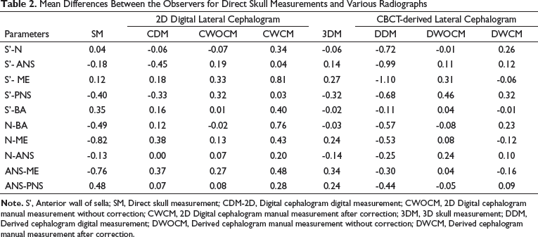
Mean Differences Between the Observers for Direct Skull Measurements and Various Radiographs
Mean Difference Percentage Between the Direct Skull Measurement and Different Radiographs
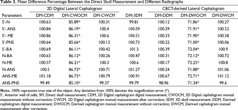
S’, Anterior wall of sella; SM, Direct skull measurement; CDM, 2D Digital cephalogram digital measurement; CWOCM, 2D Digital cephalogram manual measurement without correction; CWCM, 2D Digital cephalogram manual measurement after correction; 3DM, 3D skull measurement; DDM, Derived cephalogram digital measurement; DWOCM, Derived cephalogram manual measurement without correction; DWCM, Derived cephalogram manual measurement after correction.
Graph Showing the Mean Differences Between the Direct Skull Measurements and Different Cephalograms. (S’- Anterior Wall of Sella, SM- Direct Skull Measurement, CDM- Digital Cephalogram Digital Measurement, CWOCM- Digital Cephalogram Manual Measurement Without Correction, CWCM- Digital Cephalogram Manual Measurement After Correction, 3DM- 3D Skull Measurement, DDM- Derived Cephalogram Digital Measurement, DWOCM- Derived Cephalogram Manual Measurement Without Correction, and DWCM- Derived Cephalogram Manual Measurement After Correction).
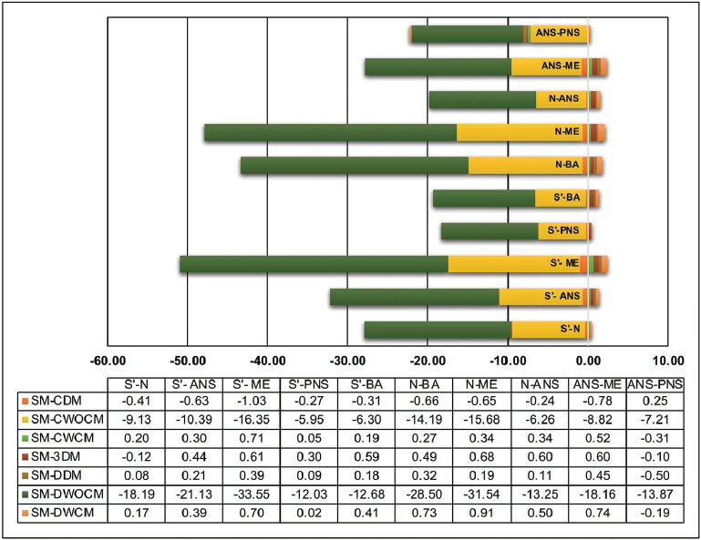
There was an inbuilt magnification of 33.33% in the 2D digital cephalograms (Size: 13.8 X10.4 inches; resolution: 72 dpi) and of 0% in the derived cephalograms (10.6X8.8 inches; resolution: 200 dpi). If the magnification error and image size were not corrected for printing the cephalograms in a film size of 8X10 inches, the 2D digital and 2D-derived cephalograms showed shrinkage of about 14.7% and 28.5%, respectively, when compared to the true size.
Discussion
In 2D radiographs, the magnification is primarily because of the geometry of the x-ray beam and it varies with different machines.11, 12 The difference in magnification between cephalograms makes it impractical to superimpose the serial radiographs, compare it with the longitudinal data,and assess outcomes in multicentric studies. In the present study, the as-received printed radiographs had variation in measurements of around 14% to 28% compared to the true size. It could be inferred that in printed cephalograms, such a vast difference in linear distance because of magnification error is well beyond the acceptable limits. Therefore, magnification correction is critical when manual tracing or superimposition has to be performed.
Various methods have been used in the past to standardize or correct the magnification of cephalogram such as fixation of film-object distance, 13 enlargement compensation scales, 1 use of photographic enlargement technique for comparison of serial radiographs of adult patients, 7 orienting all the radiographs in the same coordinate systems using a computer program, 3 and reducing the distance between film and target object. 9 The most common method is the use of the formula of proportion modified for radiographs by Adams. 2 However, the distance between x-ray source, object, and film must be known. Another common method is the use of a standard magnification factor based on manufacturer instructions. After the introduction of metallic ruler in x-ray machines, they are widely used for calibration, particularly in digital applications. 12
Employing the method described by Cohen, 4 the magnification of the digital cephalogram was made equivalent to the conventional cephalogram for superimposition. It will ensure that both the cephalograms will have the same magnification, but cannot guarantee the object's true size. Also, when compensating for a larger magnification, this method may provide an undersized image. For example, if a cephalogram had 13% magnification, a 100-mm long radio-opaque object will measure 113 mm. Reducing it by 13% of the radiographic length (i.e, 113 mm) will give 98.31 mm and not 100 mm (true length). So the final image size has to be reduced by 13% of the original ruler size (ie,100 mm) and not 13% of the magnified ruler size (i.e, 113 mm). This error is directly proportional to the distance measured. From the validation study, it can be inferred that the method we proposed in this study to standardize and print both digital and derived cephalograms is highly accurate as compared with the direct skull measurements.
With the advances made in digital technology, it is possible to derive 2D images from a 3D volume. In contrast to the digital cephalogram, where both magnification and size correction was necessary, the orthogonal derived cephalograms required only the size correction. The digital measurements from CBCT-derived cephalogram were accurate, and the printing of this cephalogram directly without adjusting the image size equal to that of film size would result in image shrinking. Unlike the orthogonal cephalograms, the perspective projection requires magnification and size correction similar to the conventional/digital cephalograms.
The same method can also be used for the standardization of frontal cephalograms. As the landmarks in the frontal cephalogram do not lie in the same coronal plane, it is recommended to perform the magnification correction using the method described by Hsiao et al. 8 and then print the cephalograms using the technique described in this study. Once the frontal cephalogram is standardized, the DPI method can also calibrate when using digital applications. This will be helpful, particularly in cephalograms without a ruler or unknown magnification.
Though this study was performed in a limited sample, a good agreement was demonstrated between the observers. Adding more samples might show a similar mean difference, and it would only add to time and effort. Using the technique described in this study, future research may be designed to evaluate the standardization of various images such as conventional 2D frontal cephalogram or 2D cephalograms derived from perspective projection, CT, or MRI.
Conclusion
The similarities in measurements among the gold standard measurements and printed radiographs after magnification/size correction indicate the following:
The proposed method can be used for standardizing and printing cephalograms obtained from different imaging systems such as conventional, digital cephalogram, and derived cephalograms. The methods have been validated using conventional/digital and CBCT-derived cephalograms
This method can be used while comparing the historic longitudinal cephalometric databases with recent digital cephalograms or CBCT-derived cephalograms with greater accuracy. Using this method, different cephalograms will have the same degree of magnification and the image's true size can also be guaranteed.
Footnotes
Declaration of Conflicting Interests
The authors declared no potential conflicts of interest with respect to the research, authorship, and/or publication of this article.
Funding
The authors received no financial support for the research, authorship, and/or publication of this article.
Statement of Informed Consent and Ethical Approval
Necessary ethical clearances and informed consent was received and obtained respectively before initiating the study from all participants.