
Abstract
Robotic deformable object manipulation (DOM) faces critical challenges in industrial and medical applications due to under-actuation, unpredictable deformation, and partial observability. Model-free methods often suffer from unstable Jacobians arising from ill-conditioned observations, while physics-based models typically depend on precise parameters and volumetric meshing, limiting their real-time practicality. We propose a wavelet-boundary element method (BEM) framework that leverages multiscale wavelet descriptors to control 3D deformations directly from efficient feedback modalities, such as contours and curves. By coupling wavelets with BEM, we derive an analytical deformation Jacobian that functions independently of material stiffness (e.g., Young’s modulus), relying solely on an online-calibrated Poisson’s ratio. This mesh-free formulation significantly enhances real-time performance and robustness against sensor occlusion. Validated in simulation and on the da Vinci Research Kit (dVRK) with phantom and ex vivo animal tissue, our method achieves millimetre-level accuracy. Comparative studies against Fourier-based, model-free, and online finite element method (FEM) approaches demonstrate superior stability and computational efficiency. Notably, our framework achieves convergence speeds significantly faster than online FEM by avoiding volumetric computations, while resolving ill-conditioning through spatial–frequency localization. This work advances deformable object manipulation in unstructured environments, particularly in surgical robotics, where stability under partial observability is essential. Project page: https://junleihu.github.io/projects/dwtbem/.
1. Introduction
Robotic manipulation of deformable objects is essential in both daily life (Longhini et al., 2025) and specialized applications, such as autonomous robotic surgery (Hu et al., 2024). DOM has emerged as a critical research area, yet it remains challenging due to the infinite degrees of freedom (DoFs) and complex material dynamics of deformable objects. In the absence of prior models or constraints, robots must primarily rely on shape feedback to infer deformation mechanics. This task is further complicated by unpredictable nonlinearities, particularly in scenarios that require precise control of intricate configurations.
Recent advances in DOM use shape feedback to compute robotic motions δ


Here,
However, linearizing Illustration of DOM and the unstable cases using DJM-based approach.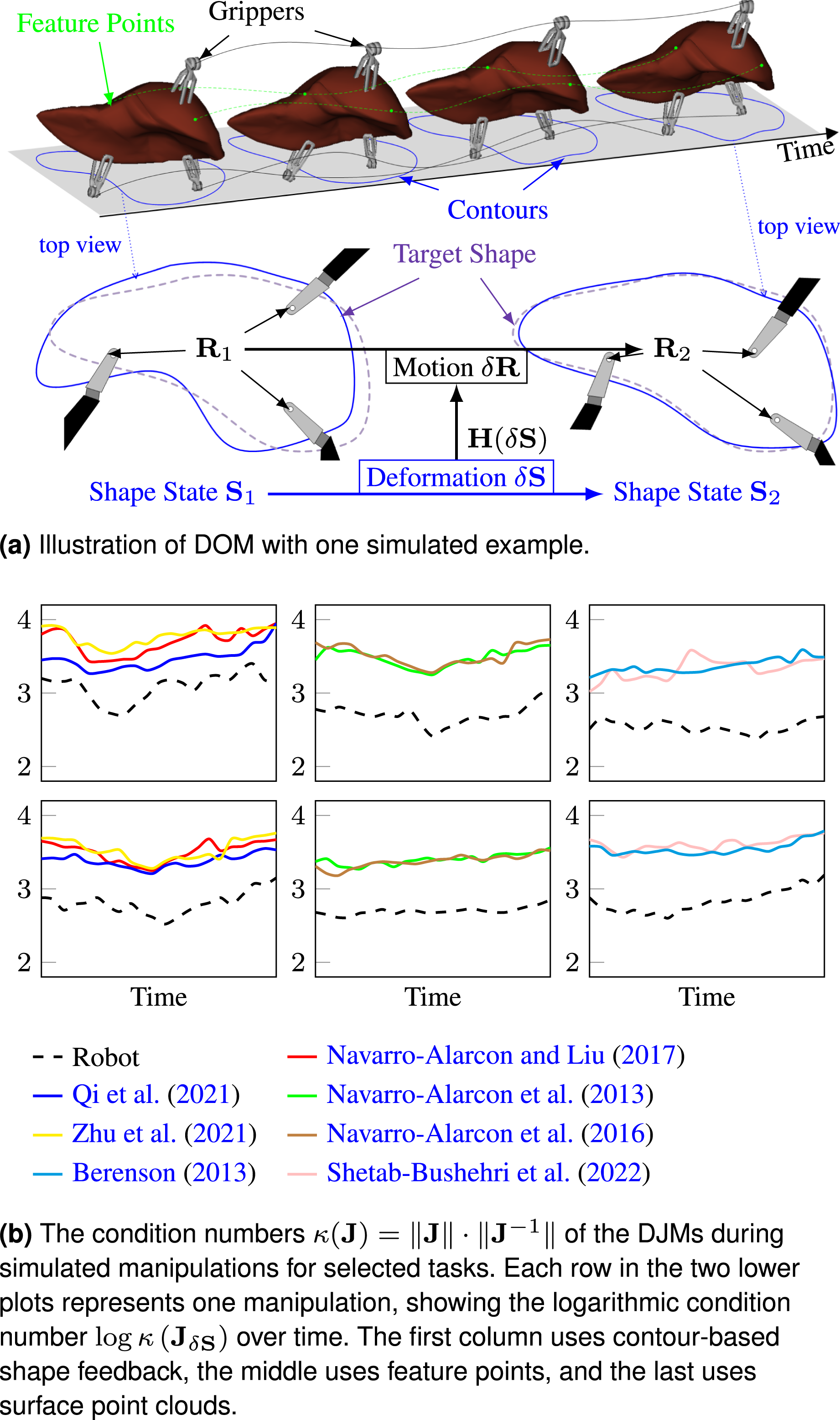
Physics-based methods derive analytical solutions by modelling material mechanics (e.g., strain energy minimization or stress equilibrium) (Ficuciello et al., 2018; Han et al., 2025), thereby avoiding the ill-conditioning inherent in DJM-based approaches. Other model-free approaches, such as the grid-point-based weight residual method (GP-WRM) (Hu et al., 2024), provide analytical displacement-motion relations to bypass these issues. Despite these advances, real-time deformation control remains a problem that involves effective shape representation and corresponding dynamics models.
1.1. Related works
1.1.1. Representation of soft object
Shape representation is pivotal in DOM, directly influencing the viability of model-based or data-driven approaches (Yin et al., 2021). Common shape feedback modalities include 2D contours (Zhu et al., 2021), sparse feature points, 3D point clouds (Hu et al., 2024; Yang et al., 2023a), and raw images. While feature points offer simplicity, their reliance on preprocessing and limited geometric fidelity restricts their utility in complex tasks (Hu et al., 2024). Similarly, raw images and point clouds necessitate non-trivial state abstractions or geometric-aware shape simplification for control, such as contour moments (Qi et al., 2021) for 2D contours, downsampled grid points (Hu et al., 2024), histogram feature (Hu et al., 2018, 2019), modal-graph (Yang et al., 2023b) for 3D surface, latent manifolds (Koganti et al., 2017), histogram-of-oriented-wrinkles (Jia et al., 2018, 2019), Variational Autoencoders (Lippi et al., 2023) for raw images, or 3D mesh or geometry directly for 3D object.
Signal-processing techniques, such as the fast Fourier transform (FFT), have been explored for shape representation in 2D (Navarro-Alarcon and Liu, 2017) and 3D (Makiyeh et al., 2023). However, its global frequency-domain encoding lacks spatial localization, making direct Fourier coefficient subtraction unsuitable for resolving local geometric discrepancies. Furthermore, its fixed spectral resolution and periodicity requirements, often managed through artificial signal completion like spherical parametrization (Makiyeh et al., 2023), limit its applicability to partial or occluded observations.
1.1.2. Physics-based models in DOM
Physics-based models, such as the FEM, discretize deformable objects into tetrahedral meshes (Ficuciello et al., 2018; Han et al., 2025; Saghour et al., 2025) to predict post-interaction deformations via physics simulations. These models enable analytic Jacobian computation for displacement-to-motion mappings (Yang et al., 2023a), as in equations (1) and (2), offering a principled foundation for control. However, the practical adoption of these methods faces critical challenges. Most require predefined 3D templates such as meshes (Saghour et al., 2025; Yang et al., 2023a), lattices (Shetab-Bushehri et al., 2023), or grids (Han et al., 2025), or have only been validated on simple parametric shapes such as circles (Das and Sarkar, 2011), ellipsoids (Makiyeh et al., 2023), and hemispheres (Dometios and Tzafestas, 2022), which limits generalization to arbitrary geometries. In addition, partial observability during manipulation, which is common in camera-based systems, restricts access to full geometric data and complicates real-time mesh updates. The high dimensionality of FEM state spaces, which far exceeds the robot’s control inputs, necessitates parsimonious representations for computational efficiency. Strategies include node reduction (Koessler et al., 2021), simplified mass-spring models (Makiyeh et al., 2023), or mesh-free approaches like position-based dynamics (Yin et al., 2021), which enforce physical constraints on particles at the cost of mechanical fidelity. A persistent challenge lies in estimating unknown physical properties online, as model accuracy hinges on precise parametrization of material behaviour.
1.1.3. Model-free approaches in DOM
Model-free strategies for deformable manipulation frequently depend on DJM predictions from interaction-deformation dynamics, yet suffer from numerical instability due to poor Jacobian conditioning under complex deformations, as evidenced in Figure 1. Approaches like the GP-WRM (Hu et al., 2024) avoid explicit Jacobian modelling by linking gripper motion to displacement fields through FEM-derived partial differential equation (PDE). While efficient, GP-WRM imposes restrictive assumptions: gripper contacts must align with observable point cloud regions to define PDE boundary condition (BC), a requirement often violated in practice when interacting with occluded or edge geometries, leading to singularities in the nonlinear mapping. Furthermore, voxel-based downsampling attenuates sensor noise inadequately and blurs fine deformation features vital for control precision. The method’s reliance on 3D point clouds also complicates integration with 2D visual feedback common in robotic-assisted minimally invasive surgery (RAMIS), as cross-modal planning remains unaddressed.
Learning-based techniques constitute a major category of model-free approaches, utilizing neural networks to approximate deformation dynamics in equation (1) or equation (2). These methods have been integrated into frameworks that combine model predictive control (Shin et al., 2019), Gaussian process regression (Hu et al., 2018), and deep neural networks (Hu et al., 2019). Other recent approaches have employed implicit neural representations to model action-conditional visual dynamics for volumetric deformable objects (Shen et al., 2024). In the surgical domain, advancements have further explored hierarchical and embodied intelligence frameworks. For instance, SRT-H (Kim et al., 2025) proposes a language-conditioned imitation learning approach to automate complex surgical tasks, while the surgical embodied intelligence framework (Long et al., 2025) leverages sim-to-real reinforcement learning to achieve generalized autonomy in tasks such as soft tissue retraction. While such methods demonstrate impressive capability in high-level task planning and execution from demonstrations, they fundamentally rely on extensive datasets encompassing diverse deformations and interactions. Consequently, their generalization remains limited to the scope of the training data, often struggling with precise, unseen tissue mechanics or novel geometries. This dependence on exhaustive, task-specific data constrains their practicality in unstructured environments where such datasets are unavailable. In contrast, our approach focuses on the low-level stability of deformation control without requiring pre-collected training data.
1.2. Our contribution
In this work, we focus on the manipulation of volumetric deformable objects governed by three-dimensional continuum mechanics, such as biological organs. We distinguish our scope from low-dimensional objects, including one-dimensional linear objects (e.g., cables) and two-dimensional thin shells (e.g., cloth). We propose a physics-based framework, named DWT-BEM which integrates the BEM with the discrete wavelet transform (DWT) to improve deformation control stability and mitigate the instability introduced by Jacobian linearization.
Unlike FEM which requires volumetric meshing, the BEM formulation is particularly advantageous for volumetric objects because it directly models boundary interactions using surface observations. This characteristic makes it ideal for vision-guided systems where only partial deformations are visible. Consequently, our approach reduces computational overhead while preserving physical consistency through stress-strain equilibrium equations.
The DWT complements BEM by decomposing deformations into multiscale wavelet coefficients, capturing both coarse global shapes and fine details. This hierarchical representation avoids the periodicity assumptions of FFT-based methods that can distort boundary conditions in open or partially observed surfaces, thereby enabling adaptive control with prioritized large-scale corrections followed by incremental refinements. Notably, DWT retains positional context even under occlusion, addressing challenges in partially observable environments like laparoscopic surgery.
The contributions of this work are: • A wavelet-BEM framework that combines the DWT with the BEM to represent 3D deformable objects. Unlike mesh-dependent approaches, this descriptor leverages the DWT’s spatial localization to handle occlusions and open surfaces, while BEM bypasses volumetric meshing for direct physical interpretation of boundary deformations. • An analytical physics-based deformation Jacobian is derived to mitigate the ill-conditioning issues inherent in model-free approaches. Unlike traditional physics-based models that require precise material characterization, the proposed formulation reduces the dependency to a single online-calibrated Poisson’s ratio, rendering the framework effectively free of manual physical parameter inputs. • A systematic benchmarking against a comprehensive suite of state-of-the-art (SOTA) strategies, contrasting our wavelet-centric method with spectral, data-driven, geometric model-free, and physics-based (FEM) approaches to rigorously quantify trade-offs in numerical stability, accuracy, and computational efficiency. • Robotic validation in laparoscopic scenarios, demonstrating applicability to surgical tasks requiring high dexterity and partial observability, where contours and curves prove to be convenient and effective feedback modalities for real-world surgery.
2. Modelling and problem formulation
Consider a deformable object Model illustration of robotic DOM using contours, curves and surfaces shape feedbacks. The corresponding targets are shown as dashed curves.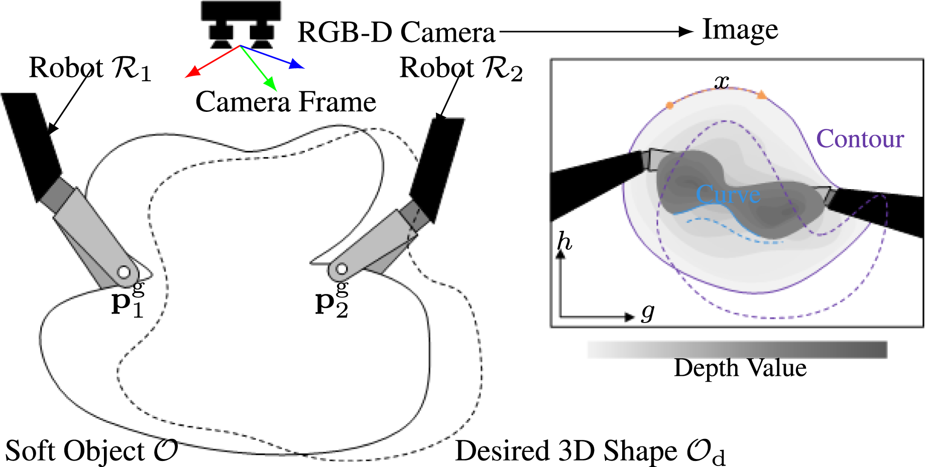
In this study, we aim to design a physics-based controller for shaping a soft object, under the following assumptions:
The object is modelled as a continuous, isotropic linear elastic material with quasi-static deformation.
Camera-robot and inter-robot transformations are known with calibration (Hu et al., 2023).
Hardware safety is maintained by joint-level kinematic limits, while tissue preservation relies on the assumption of quasi-static manipulation to minimize dynamic interaction forces.
No slip occurs at the contact points, and the robotic manipulator is modelled as backlash-free, with deformation arising only from its controlled motion.
All poses and deformations are expressed in the camera coordinate system, as illustrated in Figure 2, unless stated otherwise.
In the proposed framework, the target shape
3. Shape representation using wavelet decomposition
3.1. DWT
Given a shape
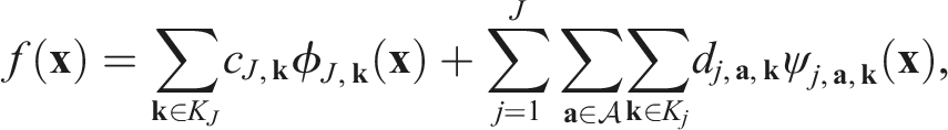

A shape
The signal is represented by the coefficient vectors
3.2. Wavelet-decomposed represented shapes
The 1D DWT provides an effective framework for representing shape feedback from 2D contours or curves in an image. The contour or curve is defined by discrete 2D pixel points, denoted as
For 3D curves, which are defined by discrete points
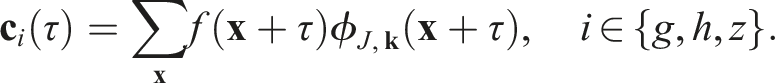
In robotic DOM applications, 3D surfaces are typically captured using RGB-D cameras and represented as point clouds, with an injective mapping that assigns a depth value to each image coordinate. The shape signal
The 2D DWT is then employed to decompose f(
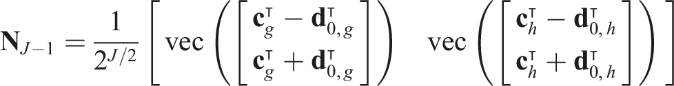
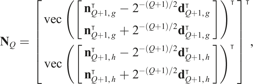
For a J-level decomposition, the surface is represented as
3.3. Adaptive sampling
The parameter x or
3.4. Missing data on the shape signal
In practice, occlusion often occurs when observing the shape, and point cloud observations may include background noise that must be filtered out, resulting in insufficient signal on the domain [0, L] or [0, L
g
] × [0, L
h
]. The DWT is well-suited to handle such cases due to properties like local support, orthogonality, and perfect reconstruction, especially when using wavelet functions such as the Haar wavelet. In the Haar wavelet transform, the approximation coefficients cJ,
Given the missing part is defined as
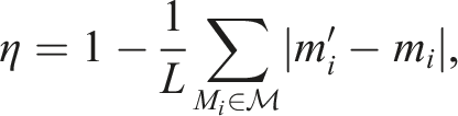
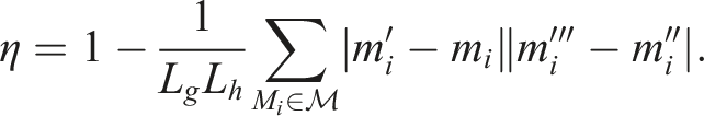
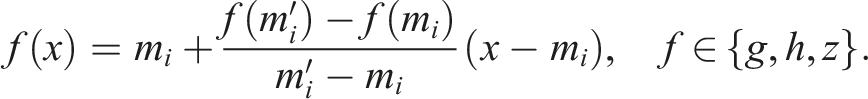
It should be noted that because η is calculated relative to the target shape’s domain, significant material stretching between the initial and target configurations can distort the arc-length mapping, which may slightly skew this completeness estimation. When the completeness ratio η is small, indicating a large missing domain, the exact content of the signal in those regions becomes less relevant, as it mainly corresponds to high-frequency coefficients that are not utilized. To ensure computational efficiency, linear interpolation is applied for curves: for each coordinate in the missing domain M
i
, the interpolated value is given by
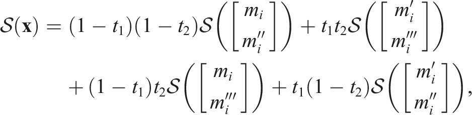
For surfaces, bilinear interpolation is used to estimate the depth in M
i
:
The corresponding coefficients with indices

4. Desired displacement field
The desired shape
4.1. Deformation field in wavelet representation
With the position-encoding nature of DWT coefficients, the deformation field is defined directly in the wavelet domain as the multiscale difference between two shape vectors:

Under the assumption of non-extensible material (i.e., the deformable object undergoes no stretching), the spatial domain remains invariant in both 2D and 3D. This permits direct computation of shape differences using wavelet coefficients without altering their positional indices, preserving the intrinsic geometric relationships across scales.
To quantify shape discrepancies, a metric space is defined over the wavelet-represented shapes. Let
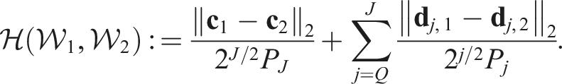
This metric aggregates the multiscale geometric differences, combining the coarse approximation (
4.2. Shape alignment in the wavelet space
The desired deformation field in the wavelet domain:
The proposed hierarchical alignment strategy iteratively resolves positional mismatches across scales, starting from coarse approximations and refining through finer details. This ensures wavelet-domain consistency before computing
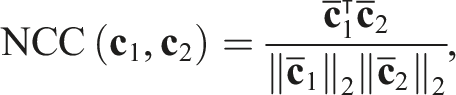
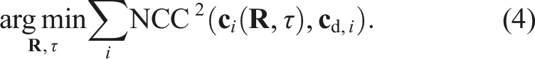
Similarity between shapes is quantified using the normalized cross-correlation (NCC) of their zero-mean approximation coefficients:
For 2D/3D curves, alignment accounts for rotational and parametric phase shifts. The approximation coefficients are transformed as
The optimization problem becomes:
For 3D surfaces, rotational alignment modifies coefficients as:

To solve these optimizations, differentiable scaling functions (e.g., Shannon wavelets) enable gradient-based methods. The differentiability of ϕ(
5. Physical model
After representing the deformable object and computing the desired displacements, a physical model is introduced to determine the appropriate actions.
5.1. Boundary element method
The deformation of an elastic object is governed by Navier’s equation:

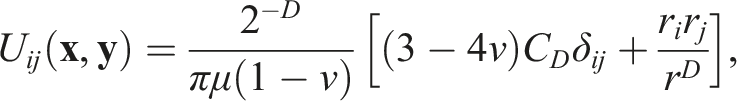
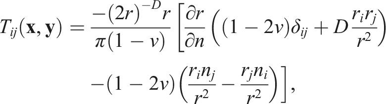
BEM solves partial differential equations by reformulating domain problems into boundary integral equations. This approach reduces the problem’s dimensionality by requiring discretization only along the boundary Γ, making it particularly efficient for problems involving infinite or semi-infinite domains. Using BEM, equation (6) can be reformulated into Somigliana’s Identity (Cruse and Suwito, 1993):

5.2. Collocation points from DWT representation
Equation (7) is solved numerically by selecting collocation points on the boundary Γ, requiring discretization of the boundary topology. Traditional physics-based approaches rely on explicit meshing for deformation analysis. In contrast, our method exploits the inherent spatial localization of DWT coefficients, which encode both geometric and positional information, eliminating the need for manual meshing. Collocation points are adaptively placed using these coefficients across resolution levels, enabling direct computation of the integrals in equation (7) and matrix assembly in equation (8). The hierarchical ordering of wavelet basis functions further allows displacement field analysis via BEM, algorithmically constructing the virtual boundary topology from the DWT.
To balance precision and computational cost, collocation points are placed at the centroid of each boundary element. The multiscale nature of the DWT supports hierarchical control: coarse representations resolve large shape discrepancies (e.g.,

Boundary nodes are reconstructed from wavelet coefficients. For Haar wavelets, the scaling function
For 2D curves, nodes at level Q = J are derived from approximation coefficients as BEM element from DWT. The black segments are the mesh and the black dots are the nodes while the grey dots are the invisible nodes. The black crosses are gripper points. (a) Contour is in purple and the target is in dashed purple. (b) Curve is in purple and the target is in dashed purple. (c) The blue dots and mesh denote the wavelet representation in higher level.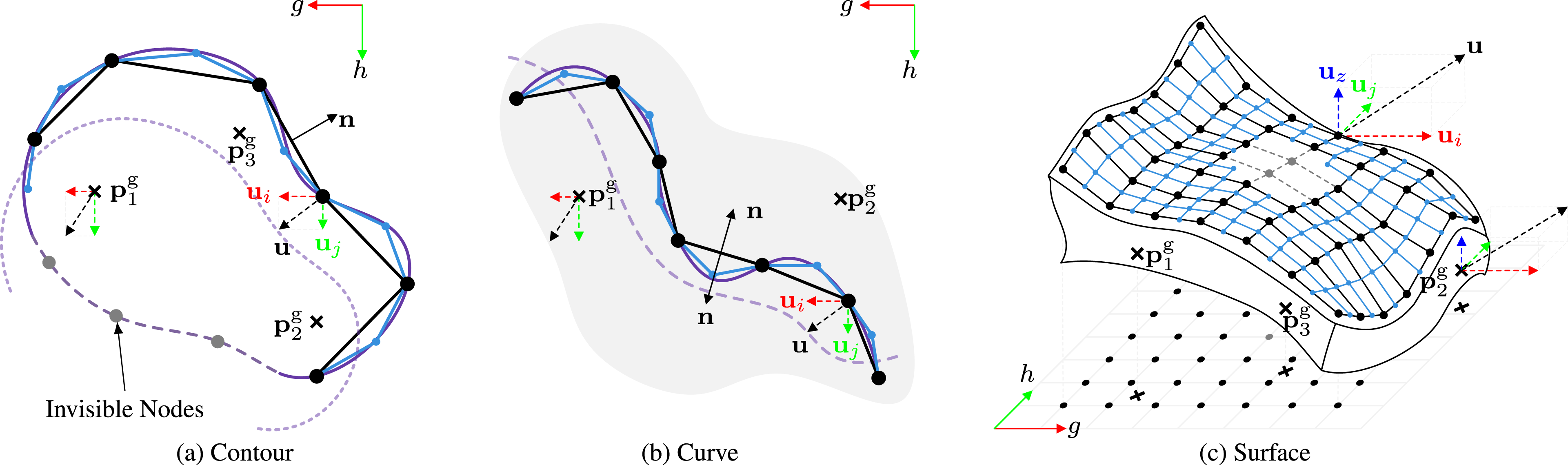
For 3D curves, nodes are reconstructed similarly to the 2D case, with the wavelet representation extended to 3D as
For 3D surfaces, nodes are parametrized over the 2D spatial domain as
The topology of Γ is defined by connecting nodes into segments or quadrilaterals (Figure 3), with collocation points at the element centroids. This wavelet-driven approach ensures adaptive resolution while preserving geometric fidelity. The corresponding coefficients are masked, specifically those with indices V j , which ensures the removal of the collocation points with these indices. Consequently, the connections corresponding to the visible indices are also excluded, maintaining a consistent and accurate representation of the visible shape. There are E elements on the topology of Γ after meshing.
5.3. Matrix form
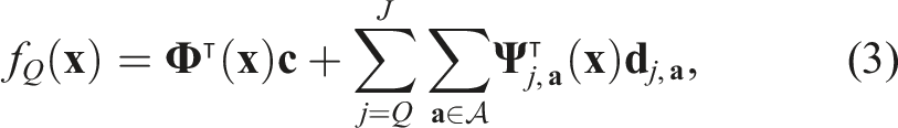
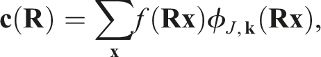
The shape function reconstructed using the IDWT in equation (3) is expressed as
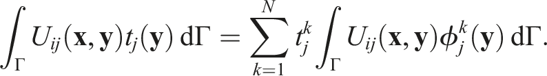
This integral is computed using Gaussian quadrature with Q quadrature points per element. Each quadrature point is given by
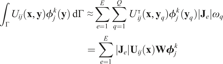
Similarly, the other integral in equation (7) is
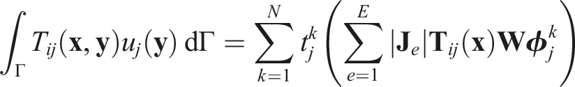
Therefore, for all nodes on the boundary, equation (7) can be expressed in matrix form as

The matrix
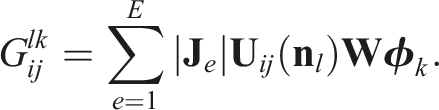
Both matrices depend solely on the geometry of the object and can be precomputed. The traction vector is assembled as
5.4. Solving interior points’ displacement with regularisation
Under Dirichlet BCs, the traction field solved from equation (8) is

The
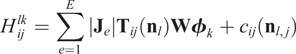
The matrix
For the diagonal entries (i = j), the integral involves a neighbourhood of node i. The fundamental solution U (
For off-diagonal entries (i ≠ j), the kernel U (
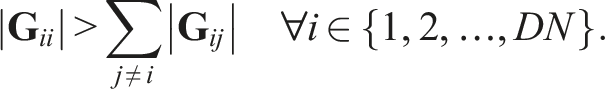
By the Levy-Desplanques Theorem (strict diagonal dominance),
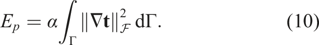
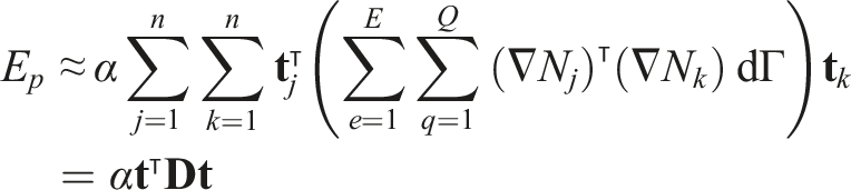
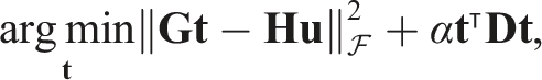
In practice, the condition of the BEM is not strictly satisfied. Thus, a regularization term is added to ensure the feasibility of this method in our cases by penalizing large gradients or discontinuities in the traction field, as
For interior points not located on the boundary, the coefficient c
ij
(

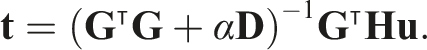
By substituting the traction vector from equation (9) into equation (11), the displacement at interior points becomes
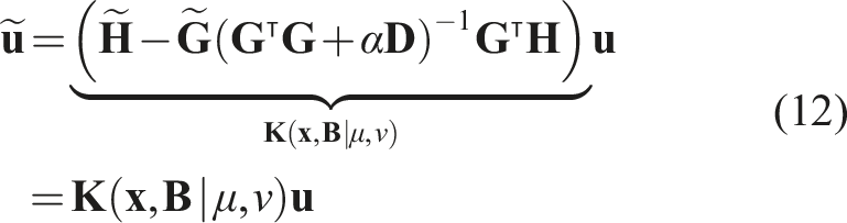
Equation (12) reveals the relationship between the observed boundary displacement and the displacement at interior locations. The positions of the gripper tips in the camera frame, either as 2D pixel coordinates or 3D world coordinates are denoted by vectors

5.5. Mechanical parameters estimation
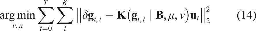
The Poisson’s ratio ν and shear modulus μ in equation (12) are unknown a priori and must be inferred from observed boundary deformations during robotic manipulation. They are critical for predicting material response and optimizing subsequent control actions. The estimation is formulated as a least-squares minimization of the discrepancy between predicted and observed gripper displacements across multiple observations:
6. Shape Servo
6.1. Iterative control
The motion of interior points in a deformable object can be related to gripper kinematics through the displacement formulation in equation (12). Given that the boundary

Robotic systems, such as the dVRK’s 7–DoF surgical forceps, enable dexterous manipulation beyond the 2D workspace constraints of prior methods (Navarro-Alarcon and Liu, 2017). To fully exploit this capability, we extend control to 3D motion by augmenting positional velocity with rotational and scaling components.
For 2D curves or contours, rotational velocity
For 3D features, positional velocity
The control strategy relies on estimating interior displacements from observed boundary deformations. However, directly actuating interior points to match a target displacement does not reach the desired boundary changes due to the nonlinear and heterogeneous properties of deformable objects. To overcome this, a closed-loop iterative controller is employed, as illustrated in Figure 4. Each iteration begins with boundary observation and the computation of the desired shape displacement toward a target configuration. The corresponding gripper motion is then calculated via equation (13) and executed accordingly. The resulting deformation is measured to update the shape discrepancy, thereby forming a feedback loop that iteratively reduces the deviation between the current and desired states. The discrepancy is quantified using the metric Schematic representation of the proposed closed-loop controller. The DWT blocks decompose the current shape 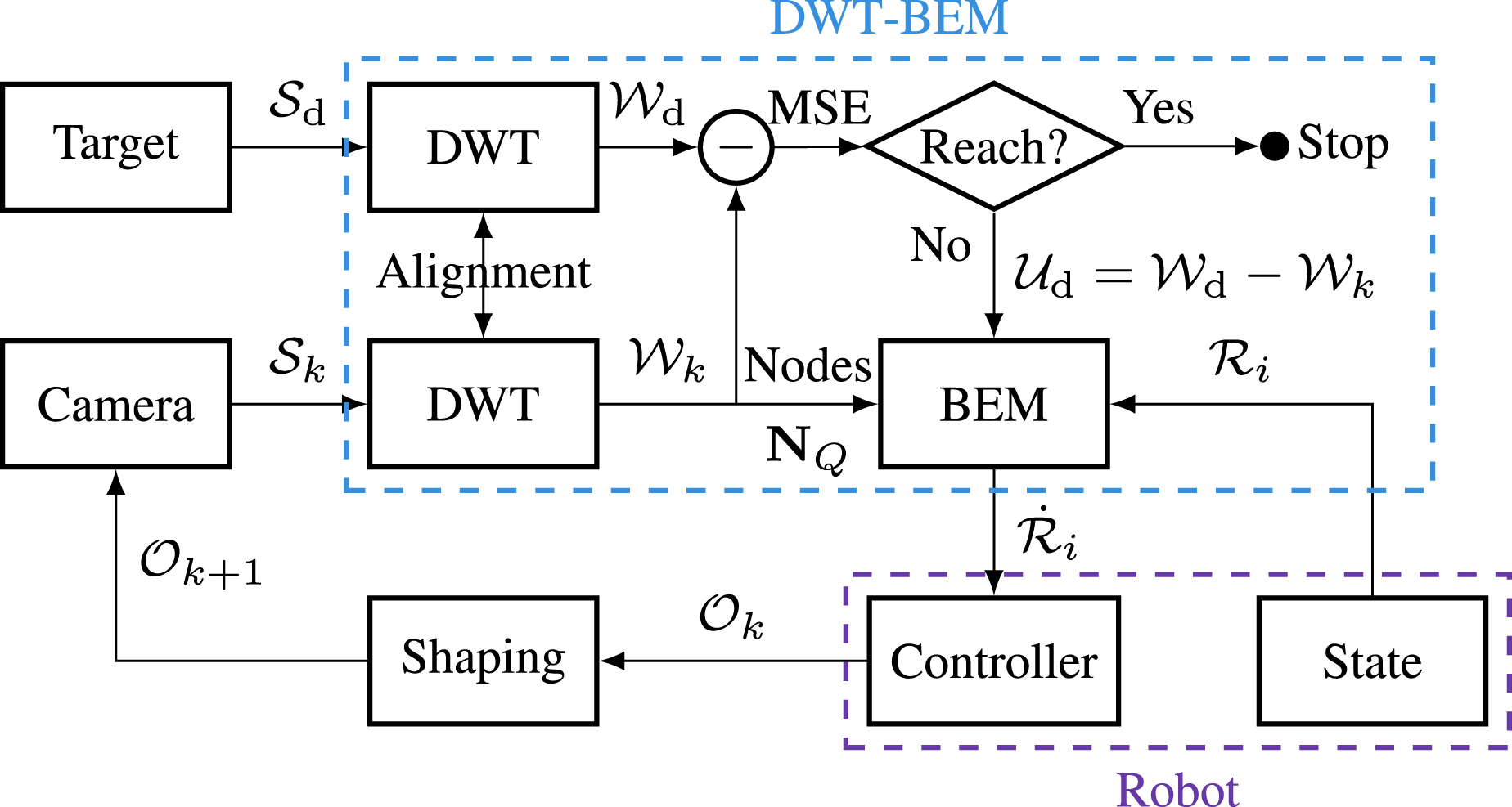
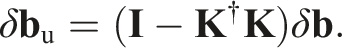
6.2. Stability analysis
As established in our previous work (Hu et al., 2024), the mapping from the robot’s finite DoFs to the deformable object’s infinite DoFs creates a non-trivial null space. While the controller explicitly minimizes error in the controllable subspace, ensuring the stability of the null space dynamics is critical for surgical safety to prevent unmodelled tissue trauma. Here, we extend the stability analysis by incorporating the physical properties of the BEM formulation.
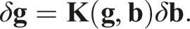
Consider the differential relationship in equation (15):
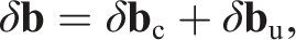
We decompose the shape variation vector δ
Local Linear Dynamics. In the neighbourhood of the equilibrium point (
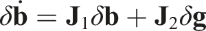
Controllable Subspace. The matrix
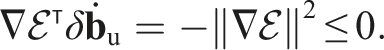
Null Space Dissipation. The deformable object is modelled as a linear elastic material governed by the BEM formulation. Consequently, deformation dynamics in the null space (uncontrollable subspace δ
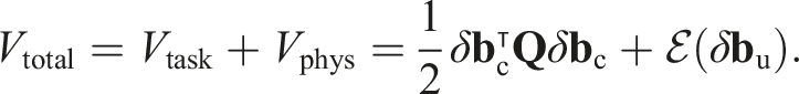
Asymptotic Stability of Controllable Error. Under Assumptions 5, 6 and Property 1, the control law
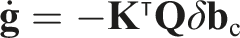
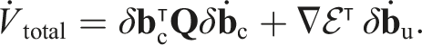
Consider a composite Lyapunov function candidate Vtotal representing the total energy of the closed-loop system, comprising the task-space error energy and the physical strain energy: Taking the time derivative of Vtotal: For the first term (controllable subspace), substituting the control law Since For the second term (null space), according to Property 1, the quasi-static material relaxation ensures that the unactuated deformation evolves to minimize potential energy: Therefore, the total derivative

The control law effectively exploits the kinematic structure of the system, with the gain matrix
Although the null space is not actively controlled, the passivity proof
7. Simulation validation
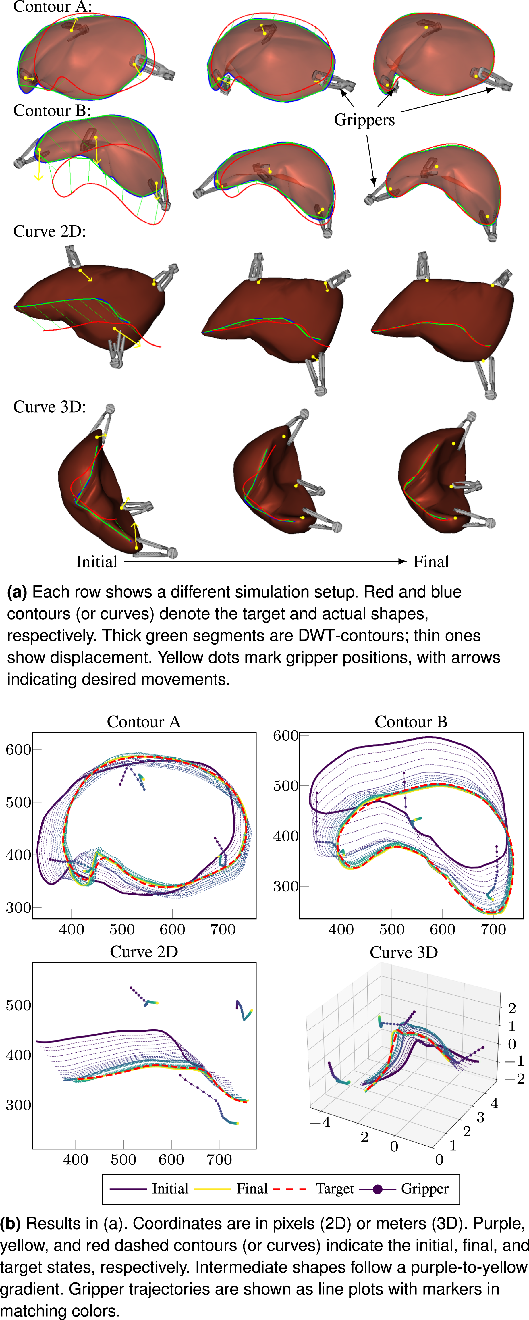
Simulation experiments were conducted using the SOFA framework (Faure et al., 2012), where deformable object dynamics were modelled with a FEM-based physics engine. A liver model was rendered as 2D images via a virtual camera at 1280 × 720 resolution. From the 2D mesh projections, contours were extracted and feature curves, defined as connected sequences of vertices and edges, were projected onto the image plane. In 3D cases, shape features were represented as point clouds sampled from visible surface or curve regions captured by the virtual camera. Occlusion was simulated by removing selected shape features within predefined regions. Three robotic grippers with known positions and full 6-DoF actuation were used to realistically manipulate the virtual mesh and reproduce interaction dynamics. Representative tasks under various configurations are illustrated in Figures 5 and 6. Additional results are available in Supplemental Video 1. Simulations using 3D surface as shape feedbacks. Simulations using contours and curves as shape feedbacks.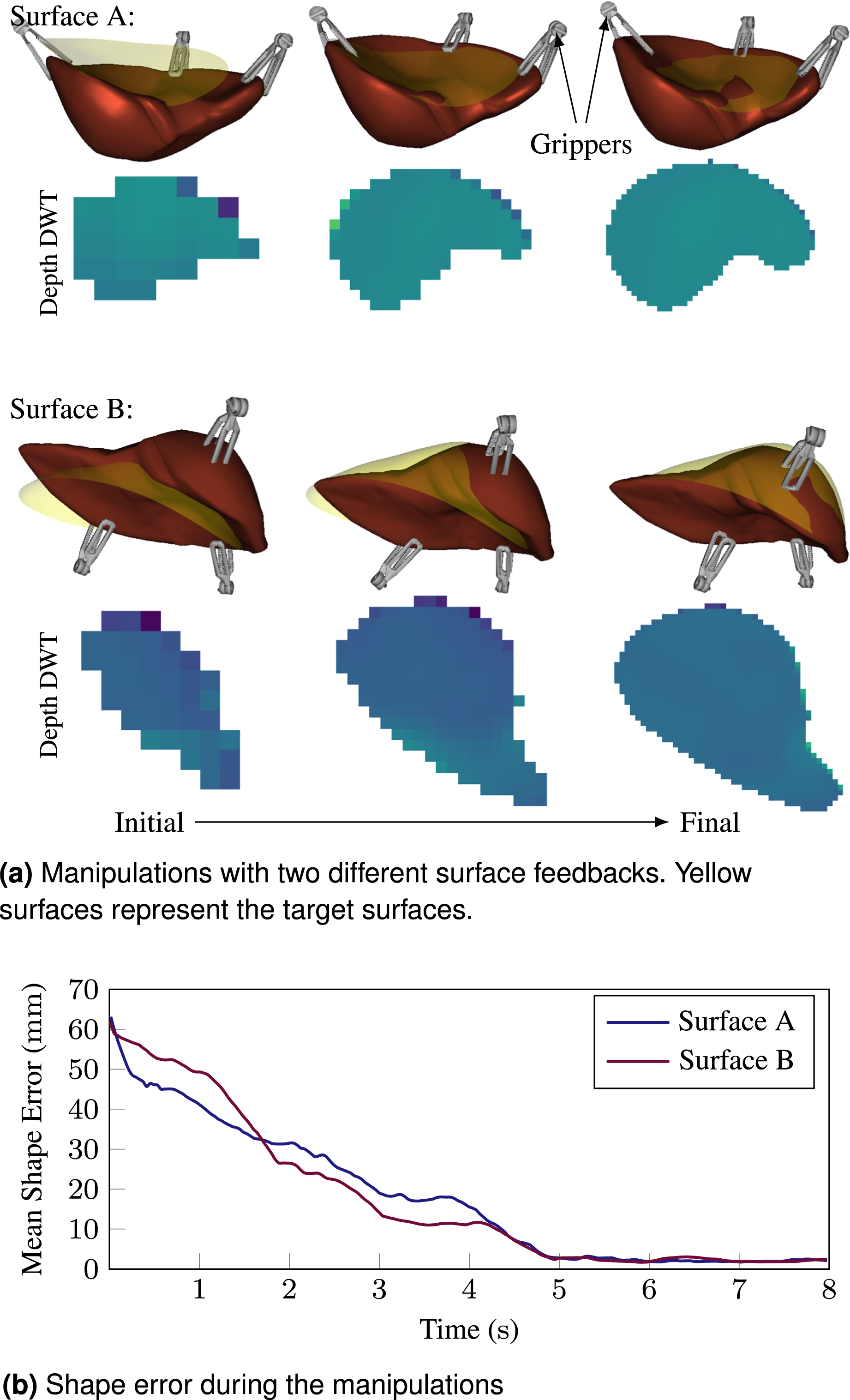
7.1. Evaluation of the physical parameters estimation
The estimation accuracy of Poisson’s ratio ν was evaluated across various deformation scenarios at a frequency of 1 Hz during manipulation. As shown in Figure 7, parameter estimation was performed under multiple configurations with different ν values. The ground-truth values, directly obtained from the simulator’s physical model, are indicated in the figure legends. Estimation of the Poisson’s ratio in the simulations.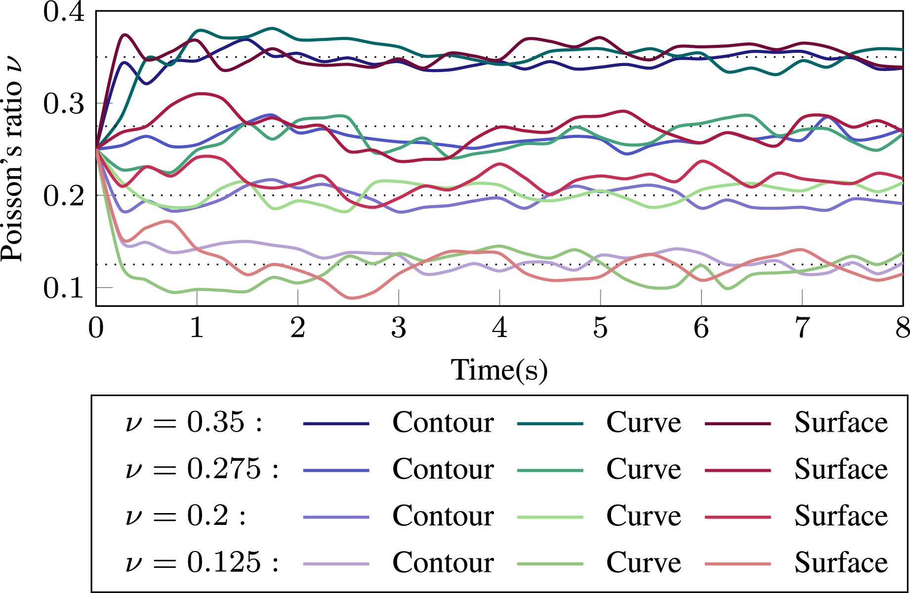
It was observed that the Poisson’s ratio ν could be approximated reasonably well when 2D contours were used as shape feedback. This is attributed to the completeness of the boundary feedback, which closely satisfies the BCs assumed by the BEM. Toward the end of the manipulation, estimation accuracy declined slightly due to reduced gripper motion. This behaviour is expected, as the estimation process depends on observable displacement. Nonetheless, the resulting error is of minor significance, given the small magnitude of the displacement field during this phase. In contrast, when shape feedback is sparse or the boundary is only partially represented, such as when the 3D curve comprises less than 30 % of the total boundary, the assumptions underlying the BEM are less well satisfied, leading to decreased estimation accuracy.
7.2. Comparison with Fourier-based shape representation
To demonstrate the advantages of wavelet decomposition, the proposed DWT-based method was compared against FFT-based strategies. Specifically, 2D contour control was implemented following the method by Navarro-Alarcon and Liu (2017), while 3D surface manipulation was adapted from Makiyeh et al. (2023).
To isolate the influence of shape representation independently from the physical modelling (e.g., BEM), a DJM-based controller was implemented using DWT features (referred to as DWT-Jac; see Appendix B). This enabled direct comparison with FFT representation under identical task conditions.
All simulations were conducted under consistent environmental settings, control gains, and target deformation profiles. Performance was evaluated based on two key metrics: shape accuracy and manipulation time. A total of 10 task groups were tested, with five focusing on contour deformations and the remaining five on surface deformations. Within each group, both FFT- and DWT-based methods were executed under the same conditions to ensure fairness.
Results shown in Figure 8 indicate that when there is a large rotational discrepancy between the initial and target shapes, FFT-based methods require more time to converge or are more likely to fail. This limitation arises because discrepancies in the frequency domain do not directly reflect geometric differences. In contrast, the wavelet-based BEM method produced more accurate gripper displacement estimates, as the physics-based model guided motion using a more spatially localized and physically meaningful representation. Comparison of shapes using FFT and DWT. The FFT for 2D contour is from Navarro-Alarcon and Liu (2017) and in 3D Surface is from Makiyeh et al. (2023).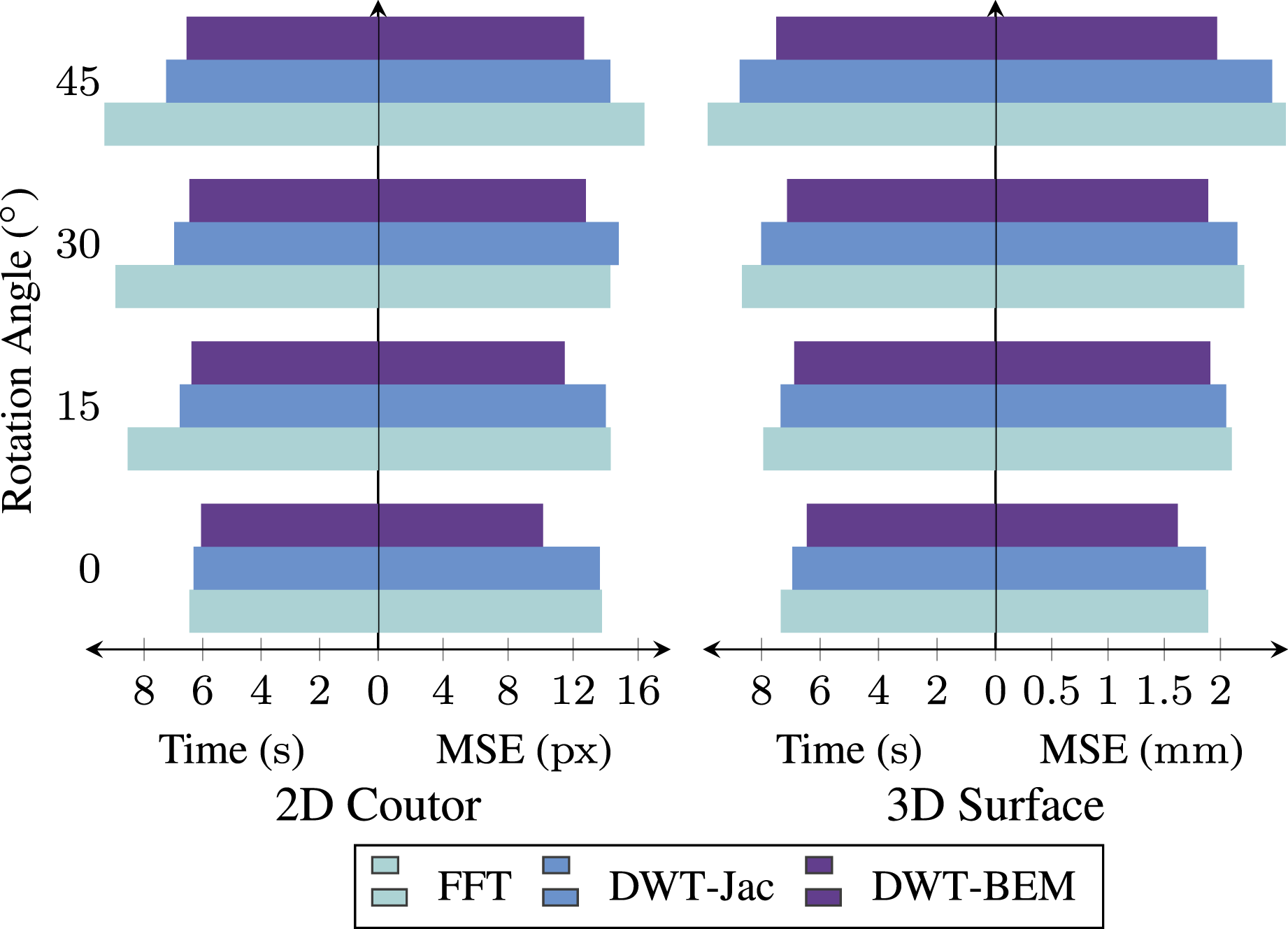
7.3. Comparison with GP-WRM
The primary advantage of the DWT-based method lies in its ability to filter noise effectively, allowing for accurate shape representation even when input data consist of partial or noisy point clouds. To illustrate this benefit, the DWT approach was integrated with the GP-WRM framework by reformulating the wavelet-approximated points as downsampled grid points, as described in Appendix C.
A known limitation of GP-WRM is its assumption that gripper contact points lie on the observable surface. To evaluate robustness under more realistic conditions, scenarios were designed in which grippers interacted with the object from positions outside the visible surface, mimicking occluded surgical instruments. Simulations were repeated ten times, with variations in the number of pre-grasped grippers.
Comparison of DWT-BEM with GP-WRM using 3D surface as feedback.
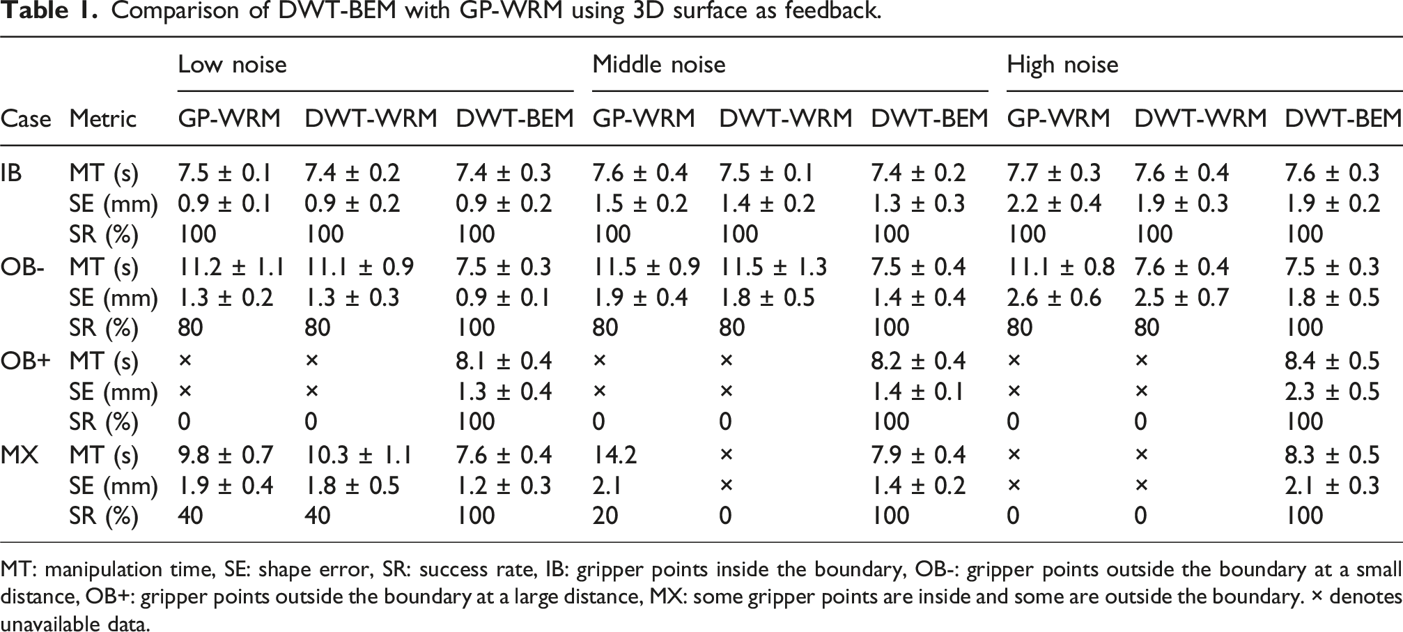
MT: manipulation time, SE: shape error, SR: success rate, IB: gripper points inside the boundary, OB-: gripper points outside the boundary at a small distance, OB+: gripper points outside the boundary at a large distance, MX: some gripper points are inside and some are outside the boundary. × denotes unavailable data.
Results summarized in Table 1 demonstrate that GP-WRM performance declines significantly as gripper positions move beyond the observed surface. When the gripper distance exceeds the defined neighbourhood radius r, the upper limit for motion correlation, the moment matrix becomes singular, resulting in task failure. While increasing r can alleviate singularities, this introduces over-smoothed deformation fields and leads to a reduction in computational efficiency by approximately 62 % to 78 %. Under low noise conditions, both methods perform similarly, as wavelet-based positions directly approximate grid points. However, as noise levels increase, the DWT method yields better surface reconstructions than GP-WRM by using low-pass IDWT, effectively filtering high-frequency artifacts.
7.4. Comparison with FEM-based method
To benchmark our proposed framework against physics-based control, we conducted a comparative study with the method recently proposed by Saghour et al. (2025). This baseline employs an online FEM to continuously predict object deformations and update the interaction matrix based on the difference between predicted and observed shapes. Both methods were evaluated in the SOFA simulation environment (v24.06) using the same liver manipulation task on a standard CPU workstation (Intel Core i7 @ 3.6 GHz). For the FEM-based approach, we utilized the standard linear elasticity model with a tetrahedral mesh (μ ≈ 1071 Pa, ν = 0.4), comprising 3286 elements. While this mesh is denser than the one used in the original study, which comprises approximately 1600 elements (Saghour et al., 2025), the setup follows the same modelling principles. While Saghour et al. (2025) originally integrate visual feedback via iterative closest point (ICP) registration to correct the simulation model, in this comparative experiment, we provided the controller with direct access to the simulation’s mesh vertices. This idealized feedback loop was chosen to decouple control performance from perception noise, ensuring a fair evaluation of the physics-based solving strategies. In contrast, our DWT-BEM method operated solely on the boundary surface point cloud (3682 triangular elements) without requiring internal volumetric data.
The results, depicted in Figure 9, illustrate the trade-off between model fidelity and computational efficiency. Quantitative analysis across 10 trials reveals that both methods achieve comparable final accuracy: the FEM-based baseline reached a mean shape error of 2.70 ± 102 mm, whereas our DWT-BEM method achieved 2.82 ± 79 mm. This similarity confirms that although BEM relies on a boundary-only formulation and does not include the full volumetric continuum mechanics modelled by the tetrahedral FEM, it provides a sufficiently accurate approximation to guide deformation control. However, the temporal profiles differ significantly. Our method reaches the target shape in approximately 8 s, exhibiting a nonlinear error descent. Conversely, the FEM-based controller shows a smooth, linear reduction in shape error, validating its stability, but at a substantial computational cost. The method by Saghour et al. (2025) required an average of approximately 3 s per iteration, with the FEM simulation alone accounting for nearly 2.3 s to reach quasi-equilibrium. This computation time aligns with the performance reported in the original study (≈1.9 s per step), confirming the standard computational burden of volumetric solvers. In contrast, our BEM computation takes only about 0.1 s. This efficiency enables a substantially higher control frequency, leading to significantly faster overall convergence to the target configuration in real-time scenarios. DWT-BEM converges significantly faster than the FEM baseline.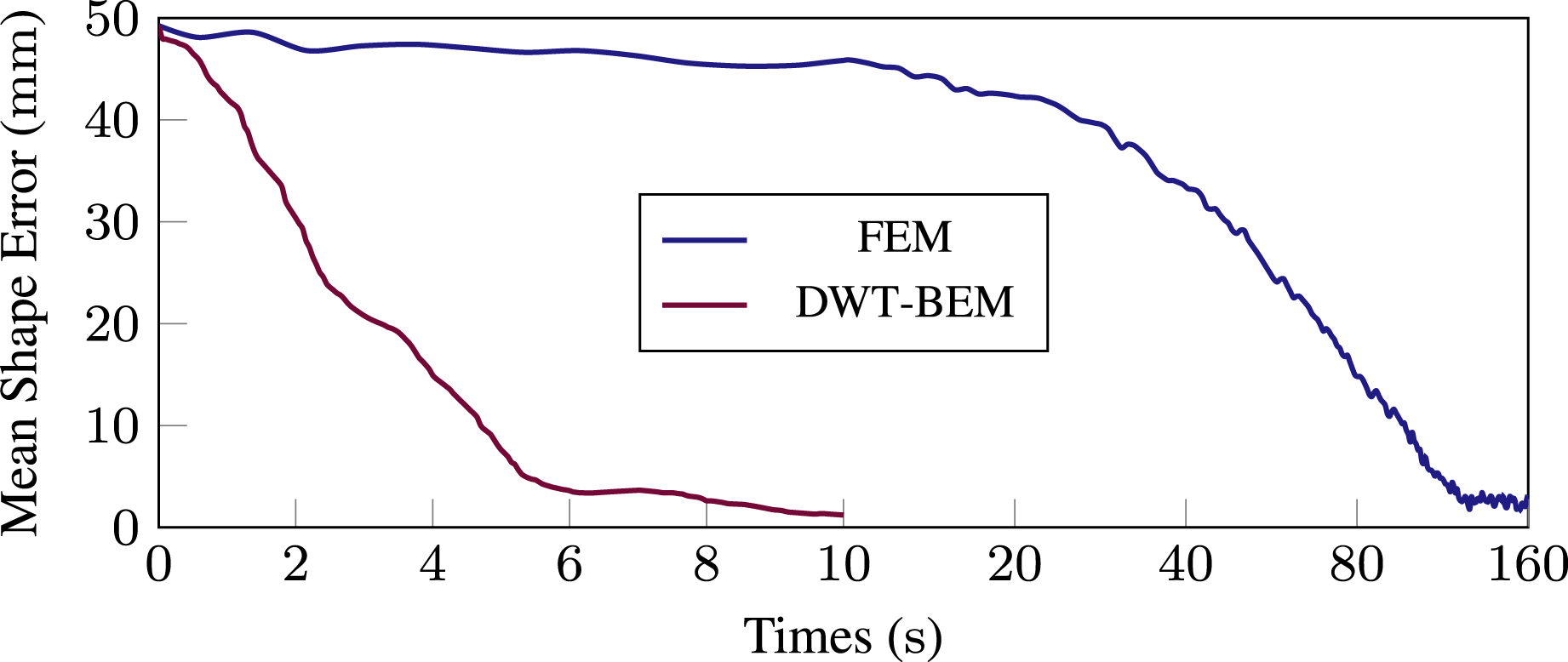
7.5. Effect of the level of DWT
The hierarchical decomposition level J and reconstruction level Q in DWT govern the granularity of shape representation, balancing computational efficiency against deformation precision. We evaluate this trade-off by analysing control accuracy and time costs across varying J and Q.
Higher J increases the resolution of wavelet coefficients, theoretically improving shape fidelity. However, this amplifies the computational load for solving the BEM problem, particularly inverting the Green’s matrix
Experiments across 2D contours, 3D curves, and 3D surfaces reveal diminishing returns: increasing J beyond Q = 2 yields marginal accuracy gains (Figure 10). This stems from two factors. First, robotic systems possess finite DoFs (n ≤ 12 for dual-arm setups), insufficient to exploit the infinite-dimensional deformation space of soft objects. Second, unpredictable nonlinear deformations during manipulation nullify benefits from higher-frequency coefficients, as cumulative errors dominate after initial adjustments, see equation (13). Thus, initializing control with approximation coefficients (lowest J) suffices for most tasks, while detailed coefficients (Q ≥1) provide negligible practical improvement at greater computational expense. Results of different levels of wavelet decomposition and reconstruction. Each block shows the MSE trend over time for one manipulation, with the horizontal axis representing time (0 s to 8 s) and the vertical axis representing MSE: 0 px to 120 px for the 2D contour, 0 mm to 50 mm for the 3D curve, and 0 mm to 66 mm for the 3D surface. The colour of each block indicates its final MSE.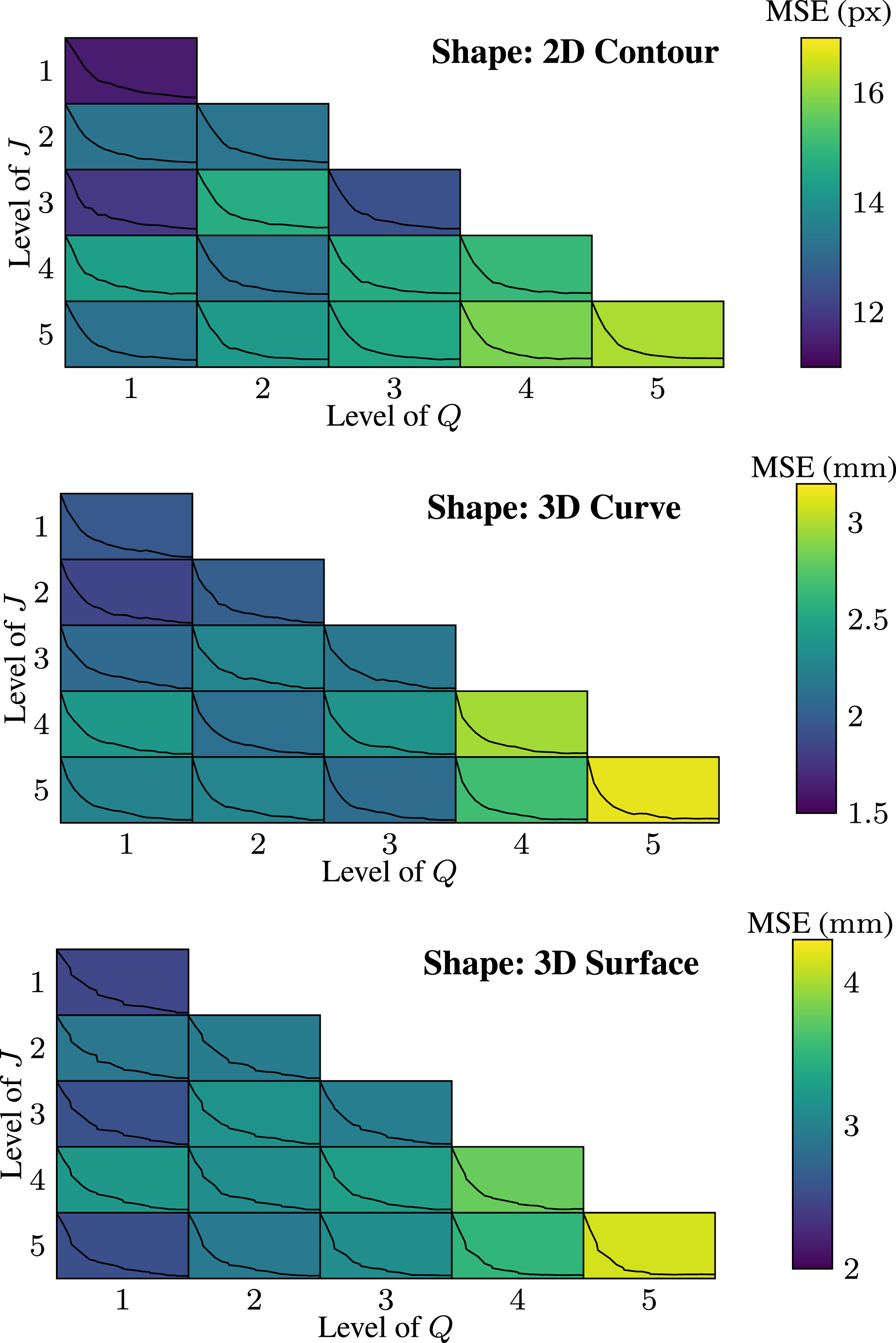
The results show that even if a high-level DWT is used, the accuracy of the shape control will not be improved a lot, as the total DoFs of the robotic grippers is much lower than the deformable object, which can be regarded as infinite DoFs. In equation (13), null space. And due to the unpredictable deformation during the manipulation, even the higher detail coefficients are used, after initial manipulations, the shape difference can be reduced, the total manipulation times is not reduced. Therefore, it is economical to just use the approximated coefficients at beginning. Even using first level of the detailed coefficient is enough. Supplemental Video 1 showcases all results.
7.6. Comprehensive comparative analysis
Comparison of the proposed DWT-BEM framework against SOTA methods. Data are derived from controlled simulation benchmarks (Section 7).
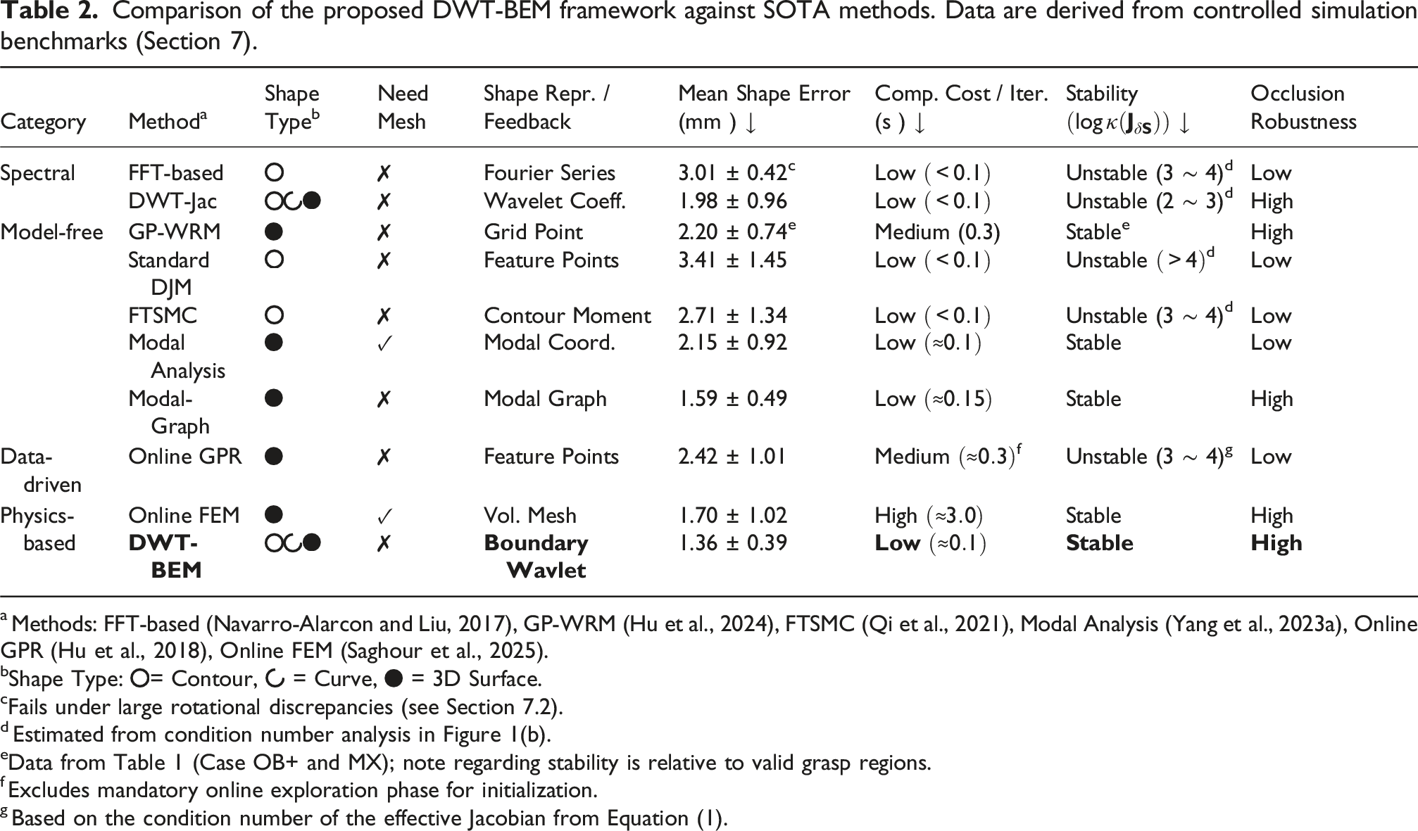
a Methods: FFT-based (Navarro-Alarcon and Liu, 2017), GP-WRM (Hu et al., 2024), FTSMC (Qi et al., 2021), Modal Analysis (Yang et al., 2023a), Online GPR (Hu et al., 2018), Online FEM (Saghour et al., 2025).
bShape Type:  = Contour,
  = Curve,
  = 3D Surface.
cFails under large rotational discrepancies (see Section 7.2).
d Estimated from condition number analysis in Figure 1(b).
eData from Table 1 (Case OB+ and MX); note regarding stability is relative to valid grasp regions.
f Excludes mandatory online exploration phase for initialization.
g Based on the condition number of the effective Jacobian from Equation (1).
In terms of accuracy and efficiency, the proposed DWT-BEM framework achieves the lowest mean shape error (1.36 ± 39 mm), outperforming both the high-fidelity Online FEM (1.70 ± 102 mm) and the recent Modal-Graph method (1.59 ± 49 mm). Crucially, our method maintains a low computational cost per iteration (≈0.1 s), enabling real-time feedback, whereas the Online FEM is significantly slower (≈3.0 s).
Specific comparisons with contour-based methods reveal the limitations of global descriptors. Both the FFT-based method (3.01 ± 42 mm) and FTSMC (2.71 ± 134 mm) exhibit higher errors and numerical instability (log κ ≈ 3 ∼ 4). This indicates that global features like Fourier series or contour moments are less capable of capturing local deformations compared to the localized boundary wavelets used in DWT-BEM, particularly when the Jacobian becomes ill-conditioned.
Data-driven approaches such as Online GPR also suffer from high condition numbers (log κ ≈ 3 ∼ 4) because of their sensitivity to local linearization errors. In contrast, DWT-BEM ensures stability through its analytical BEM formulation. Furthermore, unlike Modal Analysis and Online GPR, which degrade under partial observability, our approach maintains high robustness to occlusion. Its performance is comparable to Modal-Graph, while not requiring any offline training or online initialization phases.
8. Experiments
8.1. Experimental setup
The experiments were conducted on the dVRK (Kazanzides et al., 2014; Xu et al., 2025), comprising three 7-DoF patient-side manipulator (PSMs) and one 4-DoF endoscopic camera manipulator (ECM). The ECM was equipped with a stereo laparoscope (Intuitive Surgical, Inc., U.S.) with resolution of 1280 × 720, calibrated to sub-millimetre accuracy for 3D reconstruction (Figure 11). Notably, the dVRK platform features a hierarchical control architecture where the low-level servo controllers operate at high frequency (>1 kHz) (Xu et al., 2025), allowing for smooth execution of velocity commands derived from higher-level planners. Experimental setup for deformable object manipulation.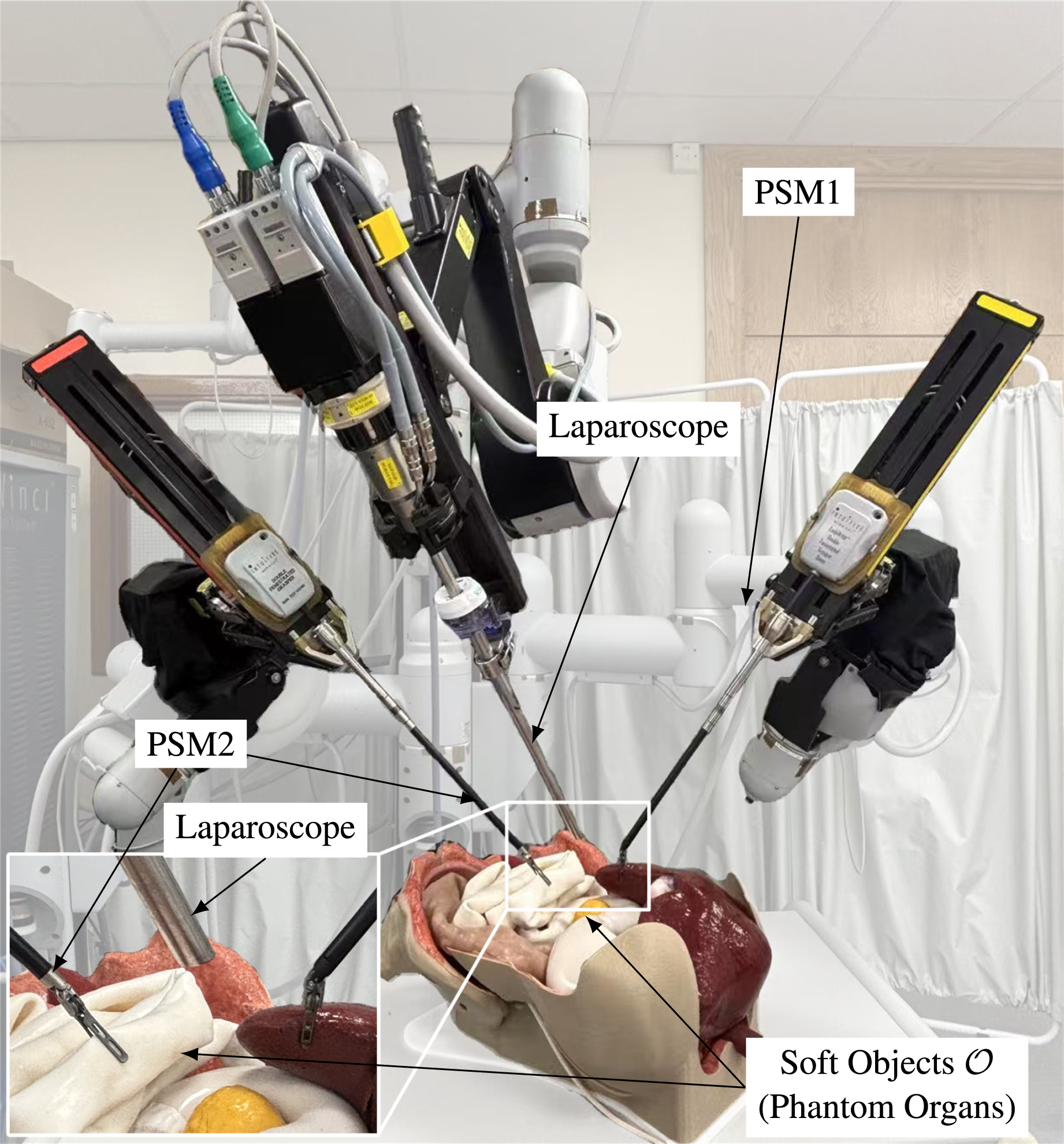
Soft tissue phantoms (EasySurg, HumanX Medical LLC, U.S.) mimicking liver, colon with appendix, and pancreas were used. These materials replicate nonlinear hyperelasticity and viscoelastic damping observed in human organs, enabling validation of surgical relevance in RAMIS scenarios. To showcase the ability of our controller in different materials, ex vivo animal experiments using porcine liver and colon were also conducted for the RAMIS.
For vision feedback, the laparoscope streamed RGB-D video at 30 fps. With 2D image feedback, only the left channel image was used. Interested organs were segmented in real time using Segment Anything Model 2 (SAM2) (Kirillov et al., 2023). Dense 3D point clouds were reconstructed via RAFT-Stereo disparity estimation (Lipson et al., 2021), with depth maps converted to Euclidean coordinates using intrinsic camera parameters. Specifically, to support the adaptive sampling in Section 3.3, we tracked approximately 3 to 8 texture feature pairs between consecutive frames alongside the gripper positions, ensuring robust node alignment even under large deformations. Point cloud updates occurred at 1 Hz to balance computational latency and deformation tracking accuracy.
8.2. Experiment on phantom tissues
When the shape feedback is 2D contour, the results are shown in Figure 12. In all cases, the contours were incomplete. For example, in the case of the colon, its elongated and folded structure prevents full reconstruction directly from the segmented image; only a partial region was selected, resulting in an open contour. This partial representation can be treated as an occlusion. Similarly, anatomical features such as the appendix or surrounding fat were partially occluded by surgical instruments or adjacent tissues. Supplemental Video 2 demonstrates all results. Manipulations on phantom tissues using contours as shape feedback.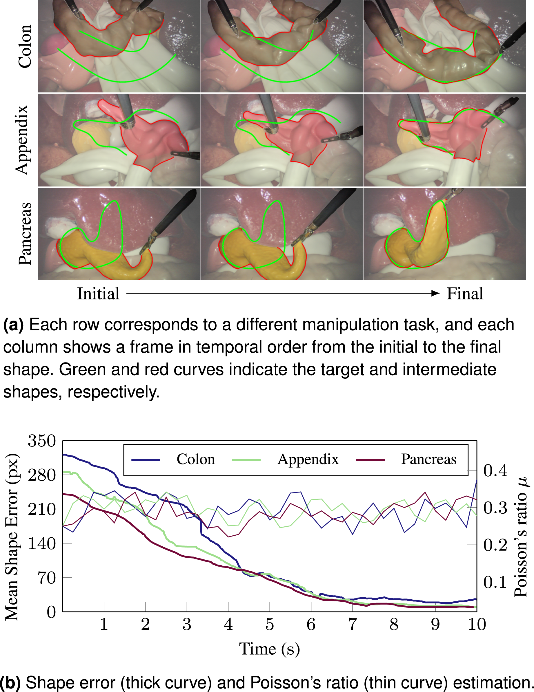
Through systematic evaluation, we observed that successful manipulation was consistently achieved when the visible portion of the contour retained a completeness ratio η of approximately 60 %. This empirical threshold represents the limit below which the rigid registration between the partial view and the target shape becomes unstable. We further analysed the impact of the occlusion location by selectively masking different geometric features. The results indicated that the controller is robust to the loss of high-curvature features. This robustness arises because the wavelet-BEM framework prioritizes low-frequency approximation coefficients for global shape servoing, allowing the system to maintain convergence even when localized high-frequency details are occluded.
We also evaluated DJM-based methods on the pancreas using contour moment (Qi et al., 2021) and FFT representation (Navarro-Alarcon and Liu, 2017). Both methods struggled to compute shape discrepancies in their respective representation spaces when the contour was incomplete, leading to task failures.
As shown in Figure 13, both 2D and 3D curves were used as the shape feedback on the liver ridges for gallbladder exposure, and a 2D feature curve on the phantom appendix with occlusion of the surgical instrument. For control of the liver ridge, 3D-curve feedback yielded a higher success rate than 2D-curve feedback. In the 2D case, when grippers are positioned on opposite sides of a curve, the boundary element method requires the object to be divided into two subdomains, allowing each gripper to be treated as an interior point relative to its respective region. However, this division introduces ambiguity in interpreting shape feedback near the curve. In contrast, in 3D, the curve lies directly on the object’s surface, and local surface normals are naturally defined. As a result, all gripper contact points are inherently interior to the domain, and the BEM assumptions are more strictly satisfied, contributing to improved control robustness. Manipulations on the phantom tissues using curves as shape feedback.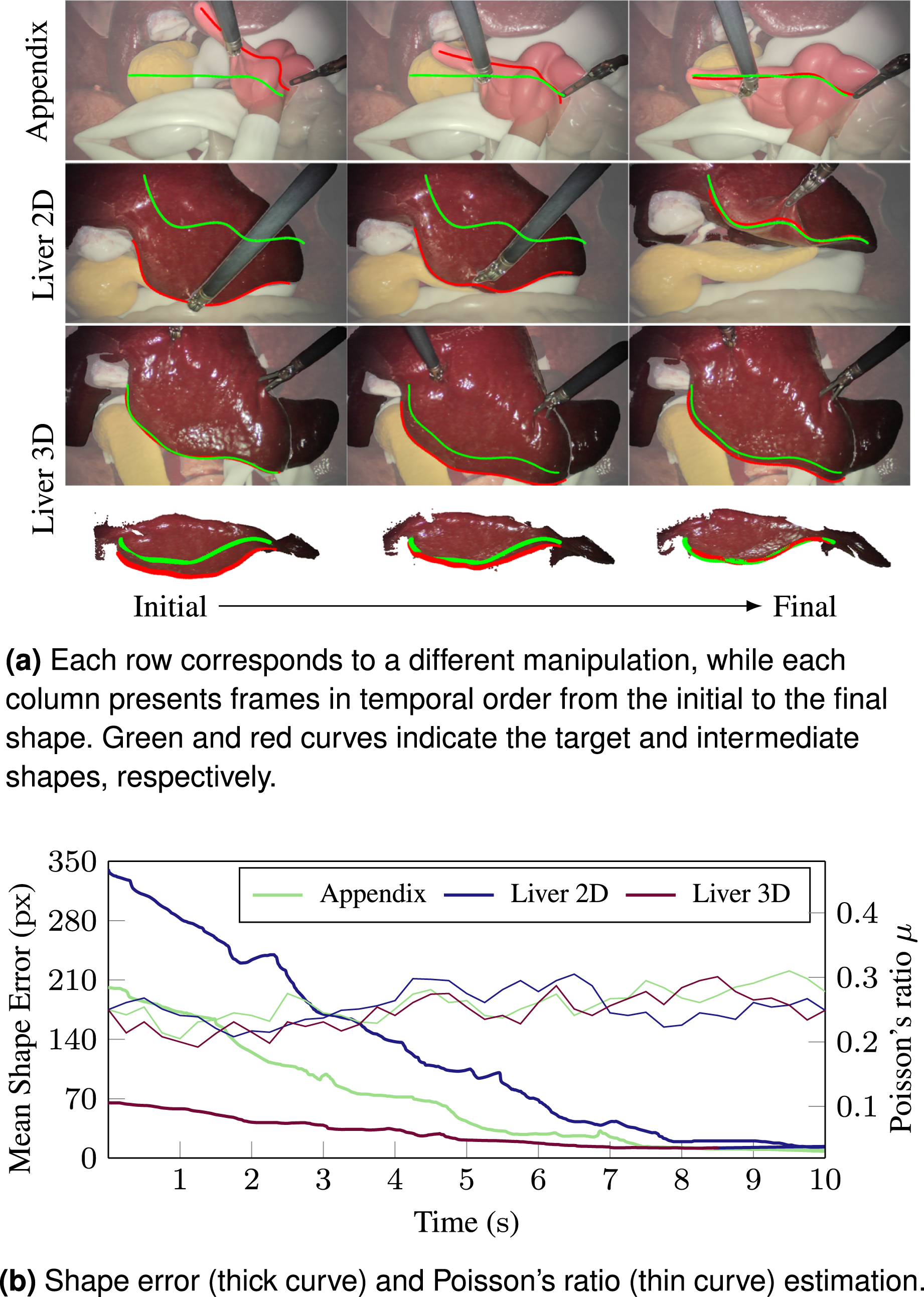
When 3D surfaces were used as feedback (Figure 14), robotic manipulations were successfully performed on the pancreas, appendix, and large intestine. In the appendix case, the left gripper, and in the intestine case, both grippers, were positioned outside the observed surface point cloud. Despite this, the method remained effective in controlling the target shape. Although parts of the surface were occluded by surgical instruments, the desired deformations were still achieved, with average shape discrepancy, MSE less than 3 mm. Manipulations on the phantom tissues using curves as shape feedback.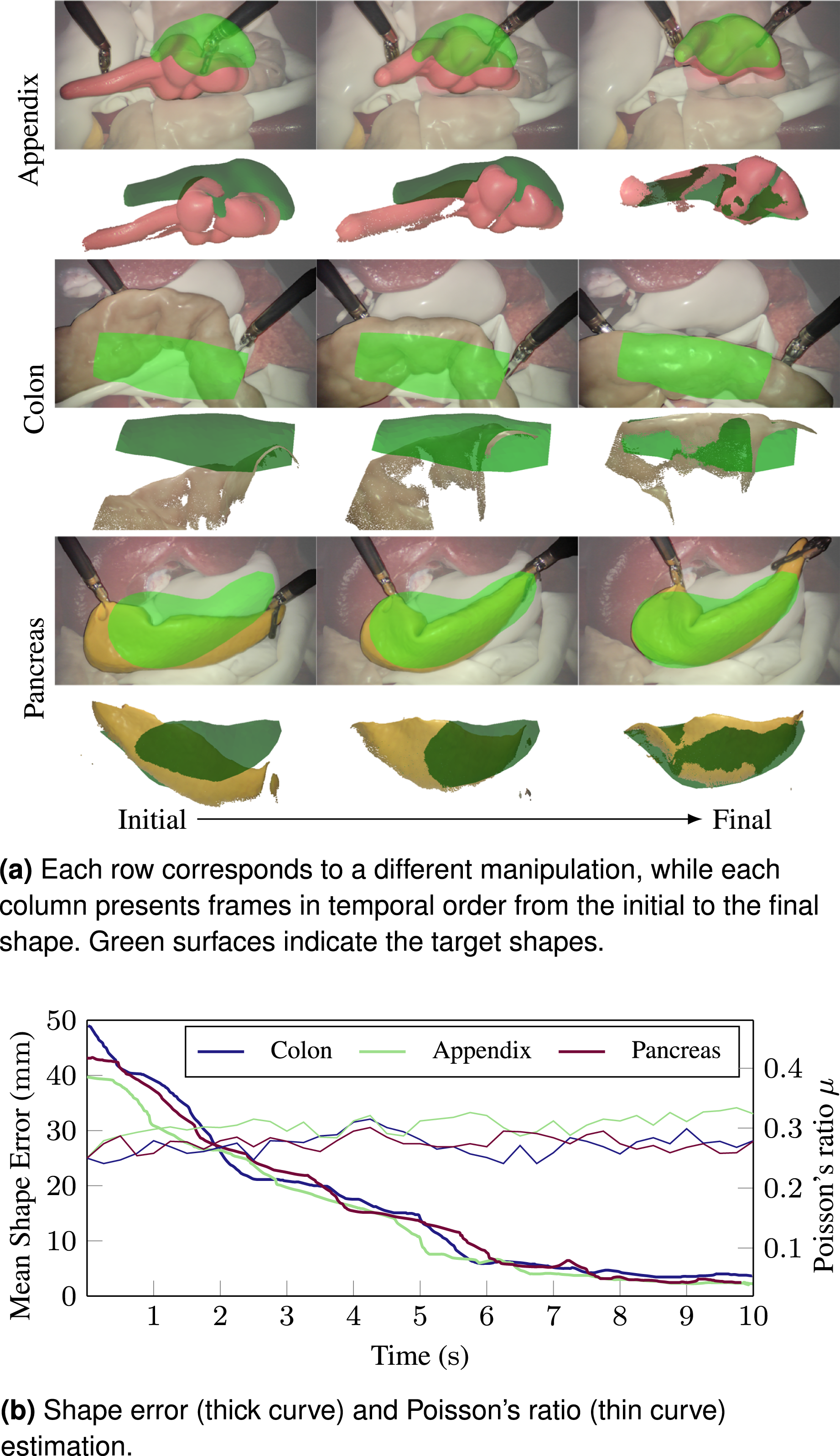
Poisson’s ratio estimations based on different shape feedback types showed slightly greater variation than those observed in simulation. Nonetheless, the results consistently indicate that 2D contours provide more reliable feedback than 2D curves, and 3D surfaces provide more reliable feedback than 3D curves. While precise identification of physical parameters is not the primary goal of this approach, the results confirm that the shape controller remains effective, owing to its iterative nature.
8.3. Experiment on ex vivo animal tissue
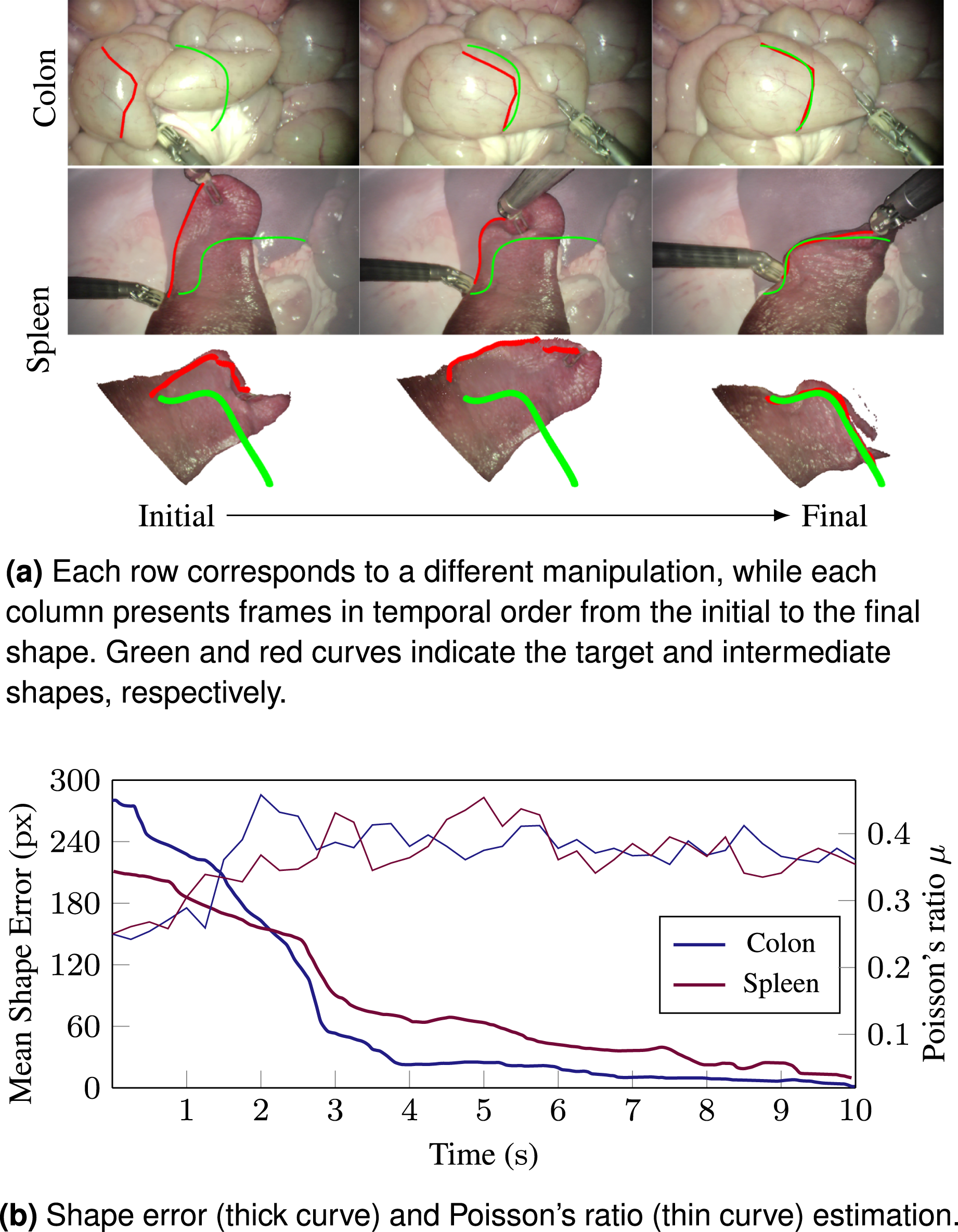
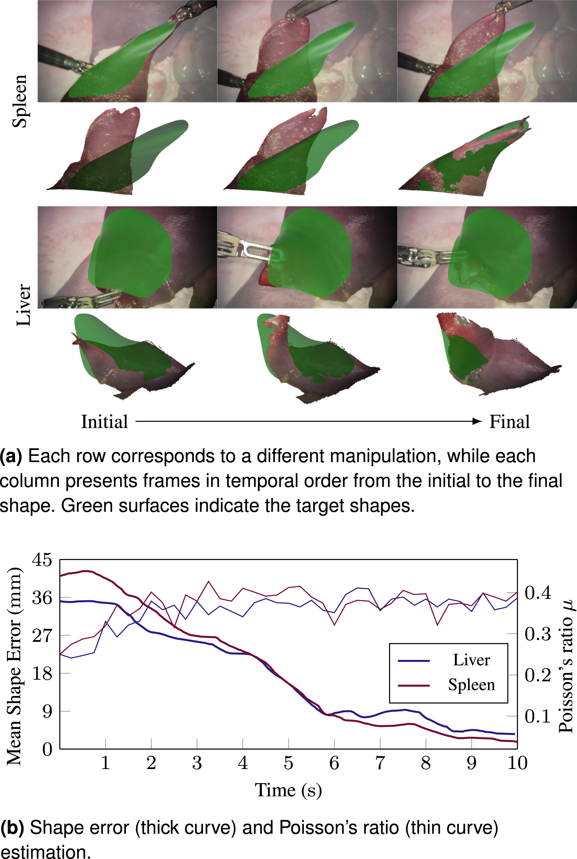
To validate the performance of the DOM in realistic RAMIS scenarios, particularly under realistic material properties, we used ex vivo animal tissue, including the full gastrointestinal tract. Manipulations were performed on organs such as the liver, spleen, and colon using three types of shape feedback, as shown in Figures 15–17. When using contour feedback, the colon with its mesentery was manipulated. For curve-based feedback, blood vessels on the colon and the superior border of the spleen were selected. For 3D surface feedback, the anterior end of the spleen and the liver lobe were manipulated. In all cases, the proposed controller successfully guided the organs to the target shapes within 10 s. Supplemental Video 3 demonstrates all results. Manipulations on phantom tissues using contours as shape feedback. Manipulations on phantom tissues using curves as shape feedback. Manipulations on phantom tissues using surfaces as shape feedback.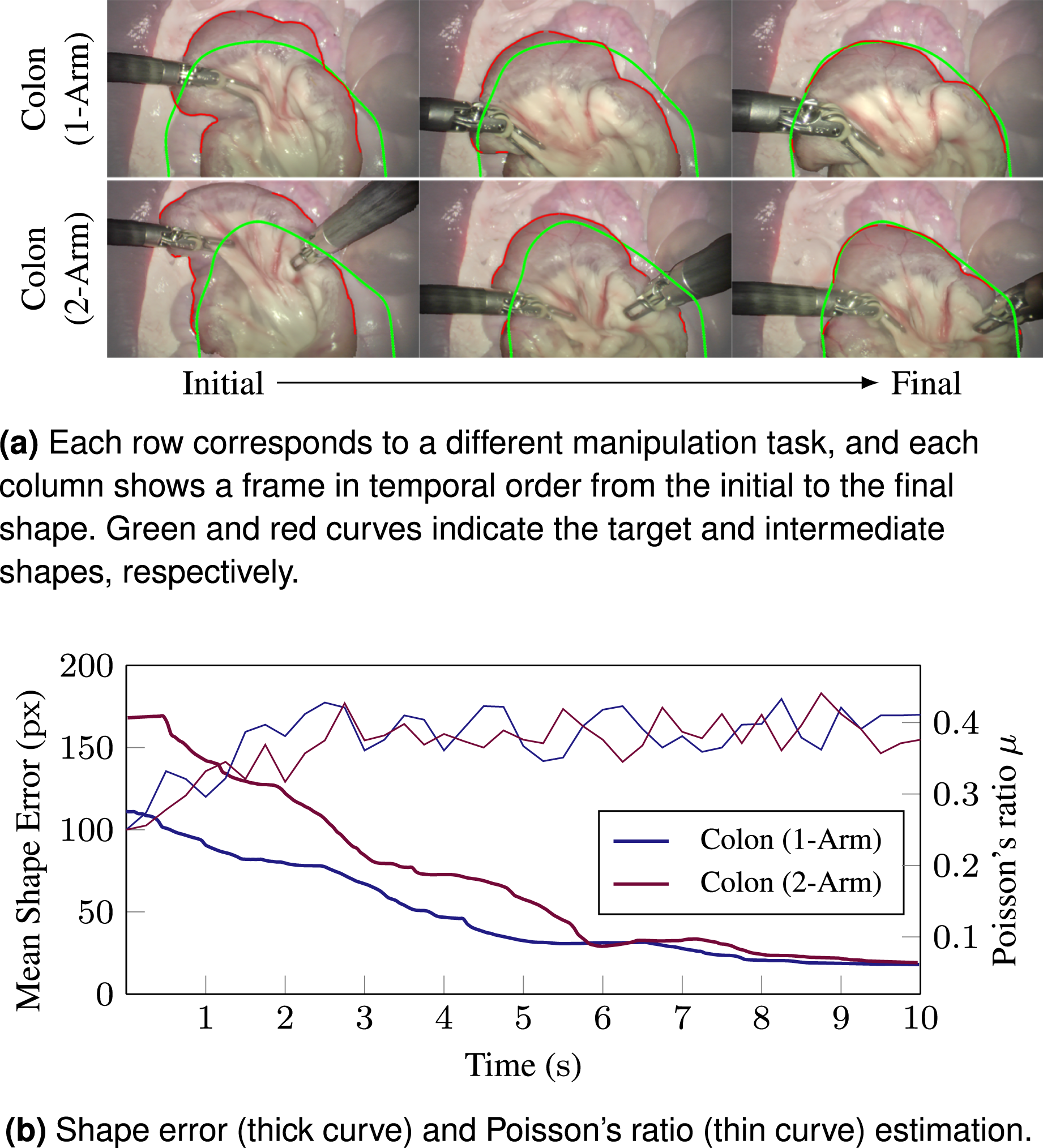
9. Discussion and conclusion
This work presents a wavelet-decomposed representation coupled with the BEM for deformable object manipulation, validated through robotic organ conformation tasks in the RAMIS platform. While traditional model-free approaches, such as those based on the DJM or nonlinear mappings, exhibit limitations in stability and observability, and physics-based methods require extensive prior knowledge of shape and mechanical properties with high computational costs, our method demonstrates superior efficiency and robustness. By leveraging BEM with only Poisson’s ratio estimation, our approach simplifies computation while maintaining accuracy, enabling real-time control through observed boundary displacements to infer interior deformations where grippers interact.
The wavelet decomposition eliminates traditional BEM meshing constraints by generating topology directly from multiscale coefficients. This integration preserves the interpretability of physics-based models while harnessing the spatial-frequency localization of wavelets, enabling targeted updates to the displacement field. Unlike Fourier-based methods, which require global recomputation and lack positional context, wavelet coefficient subtraction directly encodes shape differences at specific locations, bypassing inefficient spectral approximations.
A key feature of the proposed DWT-BEM framework, compared to purely geometric methods, is its adherence to physical laws. While geometric methods interpolate visual features and may produce physically implausible motions, our approach ensures the commanded velocity field satisfies the governing equations of static equilibrium. In this study, we focused on robustness to unknown materials. As shown in the derivation of equation (12), the traction field links boundary and interior displacements, and substituting it into the domain equations causes Young’s modulus to cancel out. This allows the controller to operate without knowledge of tissue stiffness, a major advantage in unstructured surgical environments. The parameter-free design comes with a trade-off for active safety: explicit traction values are not computed, so interaction forces cannot be directly monitored. Consequently, while the kinematic trajectories generated by the BEM provide a form of “passive” safety by strictly adhering to static equilibrium, this relies heavily on the assumption that the high-level target shape
A critical consideration in surgical robotics is the balance between control bandwidth and system stability. While our BEM-based deformation planning operates at approximately 10 Hz, the system maintains robust stability through a hierarchical velocity-control architecture. The solver computes a continuous velocity command from equation (15), which is executed by the dVRK’s low-level servo controllers operating at high frequency (>1 kHz) (Xu et al., 2025). This separation ensures smooth trajectory interpolation between visual updates and prevents the discretization artifacts typically associated with low-bandwidth position control. Furthermore, the risk of latency-induced instability, which is common in rigid haptic systems, is inherently mitigated in our setting. The quasi-static manipulation of viscoelastic and overdamped soft tissues naturally suppresses high-frequency phase lag effects and contributes to stable closed-loop behaviour.
Complementing this temporal stability, the framework also addresses potential spatial convergence issues, such as the risk of local minima in optimization-based servoing. It is essential to distinguish between the rigid alignment defined in equations (4) and (5) and the deformation control defined in equation (15). Even in scenarios where the rigid registration converges to a local optimum and results in an imperfect coordinate match, the shape discrepancy between the current and target objects typically remains non-zero. Consequently, the BEM-based controller continues to generate non-zero velocity commands. Since the Jacobian explicitly models the global physical connectivity of the object, any remaining shape difference is mapped to a physically admissible velocity field. This continuous motion drives the robot to deform the object, alters the geometric landscape, and prevents the system from becoming trapped in alignment-induced local minima.
In practical surgical scenarios, the planned target shape may occasionally be physically unreachable given the limited number of grippers and their specific grasp locations. Experimental results (see Supplemental Video 4) demonstrate that the proposed DWT-BEM controller exhibits robust behaviour in such cases. Rather than diverging or exhibiting unstable oscillations, the system converges to a bounded, non-zero steady-state error. This asymptotic convergence occurs because the control inputs eventually reach an equilibrium with the internal elastic restoring forces of the tissue. The inability to fully eliminate the error in these scenarios is attributed to Saint-Venant’s Principle (Timoshenko and Gere, 2012) and the viscoelastic nature of the material. The deformation energy applied by the grippers dissipates during propagation, which physically limits the control ability over boundary regions distant from the actuation points. While the controller ensures stability by maintaining bounded motion, consistent with the dissipation characteristics described in Property 1 and Remark 4, practical implementation requires higher-level supervisory logic, such as termination based on error gradients or time-out conditions, to manage these physical local minima.
The multiscale nature of wavelets further enhances computational efficiency. By hierarchically decomposing the boundary value problem, our framework adaptively discretizes the domain, reducing complexity without sacrificing accuracy. Spatial localization ensures that deformations are resolved at relevant scales, avoiding unnecessary computations in regions of minimal influence. Compared to registration-dependent approaches, which struggle with occlusion and noise, our method achieves robustness through direct wavelet-based correspondence, even under significant sensor limitations.
In addition to sensing robustness, the framework demonstrates resilience to modelling approximations. To enable real-time control, we adopt a linear elastic approximation (Assumption 1) to represent soft tissues that are inherently hyperelastic. This simplification is necessary to utilize the analytical solvability of the BEM (Cotin et al., 1999; Ficuciello et al., 2018; James and Pai, 1999), avoiding the high computational cost of iterative nonlinear solvers. Although this introduces constitutive discrepancies, our experimental results demonstrate that the closed-loop shape servoing framework effectively compensates for these modelling errors. By iteratively updating the deformation target based on visual feedback, the controller corrects residual errors caused by the linear approximation, ensuring convergence even when the constitutive model is imperfect.
Despite these advantages, our framework faces challenges under extreme operating conditions. A primary challenge arises when shape feedback is highly incomplete, for example, using sparse curves or occluded point clouds to represent complex or large deformable objects. This violates the BEM’s requirement for sufficient boundary data, leading to ill-posed boundary integral equations that amplify numerical instabilities. Another issue stems from unmodelled external forces (e.g., environmental interactions), which can introduce unanticipated dynamics that iterative control cannot fully compensate for without force feedback integration. Finally, while wavelet-based alignment avoids non-rigid registration, extreme deformations may decouple spatial correspondence between target and current shapes. This occurs when topological changes (e.g., folding or stretching) exceed the linear superposition assumptions of BEM, reducing robustness in large-displacement scenarios. Furthermore, while our feature tracking approach using optical flow (e.g., RAFT-Stereo) is effective for adaptive sampling in phantom and ex vivo setups, true in vivo environments introduce severe perceptual artifacts such as specular reflections from wet tissues, blood pooling, and surgical smoke. Addressing these visual disruptions is essential for practical clinical application.
This work advances deformable object manipulation in unstructured environments, particularly in surgical robotics where real-time responsiveness and partial observability are critical. Future directions include extending the framework to heterogeneous materials, dynamic occlusion handling, improving perception robustness in visually degraded in vivo environments, and integrating force feedback from sensorised grippers to compensate for unmodelled external forces.
Supplemental material
Supplemental Material - Multiscale deformable objects manipulation via wavelet-decomposed boundary element method
Supplemental Material for Multiscale deformable objects manipulation via wavelet-decomposed boundary element method by Junlei Hu, Dominic Jones, Majed Melibary, Jiannan Liu, and Pietro Valdastri in The International Journal of Robotics Research
Footnotes
Acknowledgements
All the experiments involving human cadaveric tissues were performed under ethical approval from the University of Leeds.
Funding
The authors disclosed receipt of the following financial support for the research, authorship, and/or publication of this article: This work was supported in part by the European Research Council (ERC) through the European Union’s Horizon 2020 Research and Innovation Programme under Grant 818045, in part by the Engineering and Physical Sciences Research Council (EPSRC) under Grant EP/V047914/1, and in part by the National Institute for Health and Care Research (NIHR) Leeds Biomedical Research Centre (BRC) (NIHR203331). Any opinions, findings, and conclusions or recommendations expressed in this article are those of the authors and do not necessarily reflect the views of the ERC, the EPSRC or the NIHR.
Declaration of conflicting interests
The authors declared no potential conflicts of interest with respect to the research, authorship, and/or publication of this article. The authors would like to thank Intuitive Surgical, Inc., for the donation of the da Vinci system, the STORM Lab technician, Samwise Wilson, for hardware support, and Dr. Benjamin Calmé for his support in the animal experiments
Supplemental material
Supplemental material for this article is available online.
Appendix
References
Supplementary Material
Please find the following supplemental material available below.
For Open Access articles published under a Creative Commons License, all supplemental material carries the same license as the article it is associated with.
For non-Open Access articles published, all supplemental material carries a non-exclusive license, and permission requests for re-use of supplemental material or any part of supplemental material shall be sent directly to the copyright owner as specified in the copyright notice associated with the article.