
Abstract
Robotic exploration of unknown soft objects presents significant challenges for autonomous systems due to unpredictable deformations and shape changes during manipulation. To address this, we propose a framework that integrates topology-aware 3D reconstruction with a topology-guided motion planner, enabling the discovery and reconstruction of previously hidden or concave regions. This topology-aware 3D reconstruction employs a novel representation of deformable objects by combining Cylinder Čech Complexes with point clouds, enabling rapid tracking of significant topology changes and detection of non-manifold boundaries. The topology analysis and canonical reconstruction guide motion planning by optimising grasp points and planning trajectories to reveal previously unseen surfaces through two actions: turning over and stretching. We validated our algorithm through simulations and experiments using the da Vinci Research Kit, demonstrating successful exploration with two or three manipulators. We showed it can fully explore surfaces of two everyday objects, a beanie and a rubber glove, and two cadaveric organs, a liver and a colon, within seven manipulations. Our method achieved a 45.6% improvement in 3D reconstruction accuracy compared to state-of-the-art point-cloud-based methods while also demonstrating the capability to detect and fix non-manifold geometry.
Keywords
Introduction
Exploring deformable objects to fully understand their shape and appearance is a fundamental task for humans in everyday life. This occurs in various activities, such as cloth processing (Sanchez et al., 2018) and garbage disposal (Kiyokawa et al., 2022), as well as in skilled professions like laparoscopic surgery (Sánchez et al., 2011). This exploration is always accompanied by manipulation, since only part of the surface is initially visible. Typically, humans form an initial perception of a soft object through sight and mentally estimate its rough shape. Based on these perceptions, they manipulate the object to reveal more of its surface, refining their understanding with each interaction. In practice, however, it can be difficult to remember all surface details clearly due to the drastic changes in morphology.
For robots, achieving autonomous exploration of unknown deformable objects is even more challenging. In robotic-assisted minimally invasive surgery (RAMIS), deformations arise not only from robot-induced movement (Figure 1) but also from respiratory- and circulatory-induced motion (Attanasio et al., 2021). Three major challenges arise at the perception, decision, and action stages. First, perceiving the shape of a soft object is difficult. As in this case with the robotic manipulation of soft objects, a representative state of the explored object surface, such as a 3D model, is necessary for the robot to refer to when making control decisions. While camera systems can perceive raw images or depth maps of the object, these alone are insufficient as the representative state. Second, determining if the soft object has been fully explored and identifying unexplored areas is challenging. During manipulations, inevitable deformations complicate the 3D reconstruction, leading to incorrect topology and making it difficult to analyse the object’s shape. Third, manipulating the soft object to expose its hidden surface is inherently complex. Grip points and manipulation paths can cause unpredictable deformations, potentially leading to failed plans or suboptimal results. System-level workflow illustrating robotic exploration with 3D canonical reconstruction, including (1) 3D point cloud collection from camera during manipulation, (2) frame-to-frame point cloud registration to align observations, and (3) 3D reconstruction via shape fusion to build the canonical model.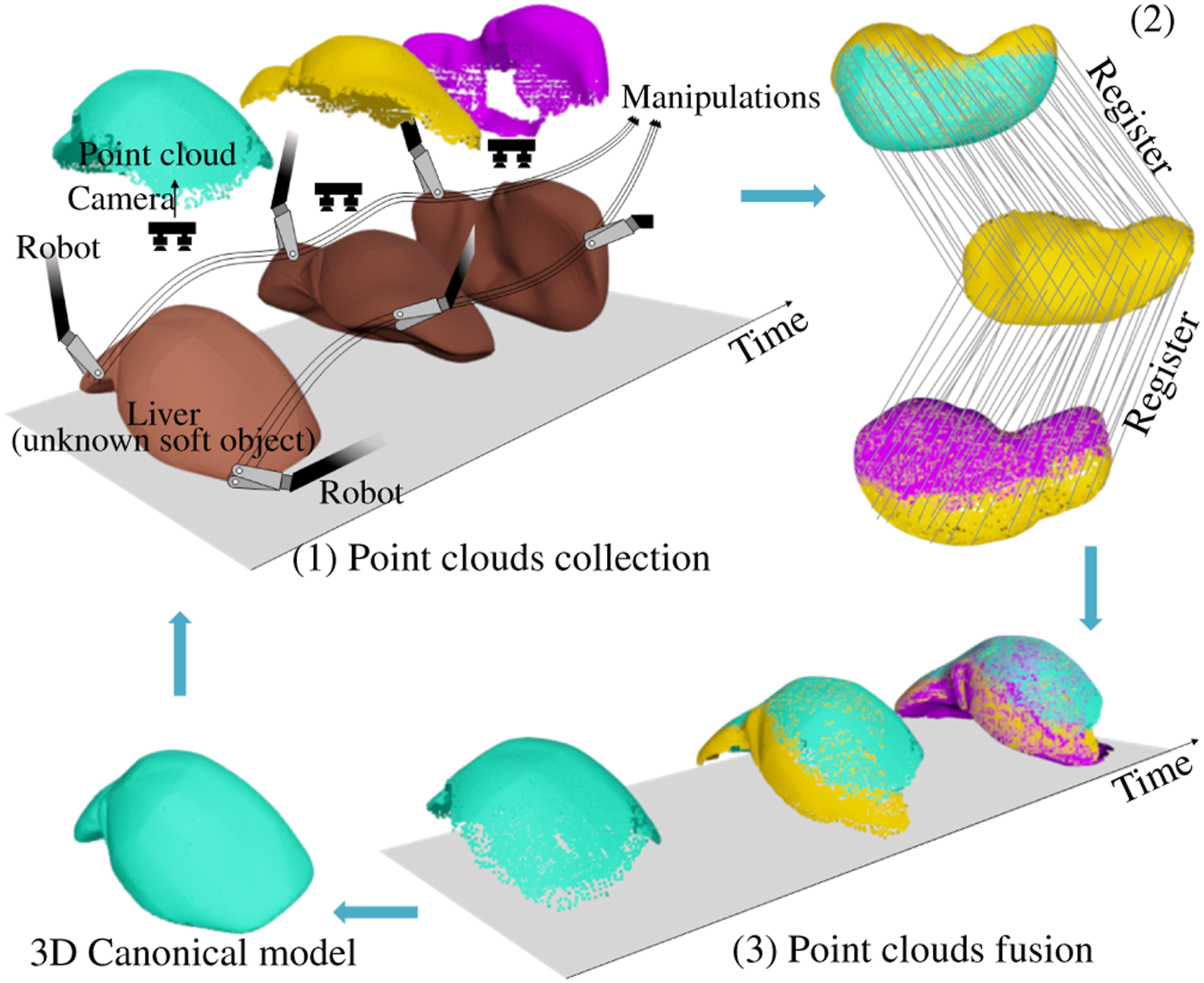
Recent advances in key technologies for robotic exploration, such as 3D reconstruction and robotic manipulation of soft objects, have made significant progress in addressing these challenges. 3D reconstruction (Figure 1) involves recovering the shape of a 3D object, using a series of discrete observations dependent on the input modality. Both registration-based and learning-based methods are used; however, they often fail when the object undergoes large deformations during the reconstruction process. Furthermore, robotic manipulation is essential in the shaping of soft objects, with shape representation being a critical factor in its solution. Especially in the context of robotic exploration, a proper representation is key to achieve real-time performance in online control.
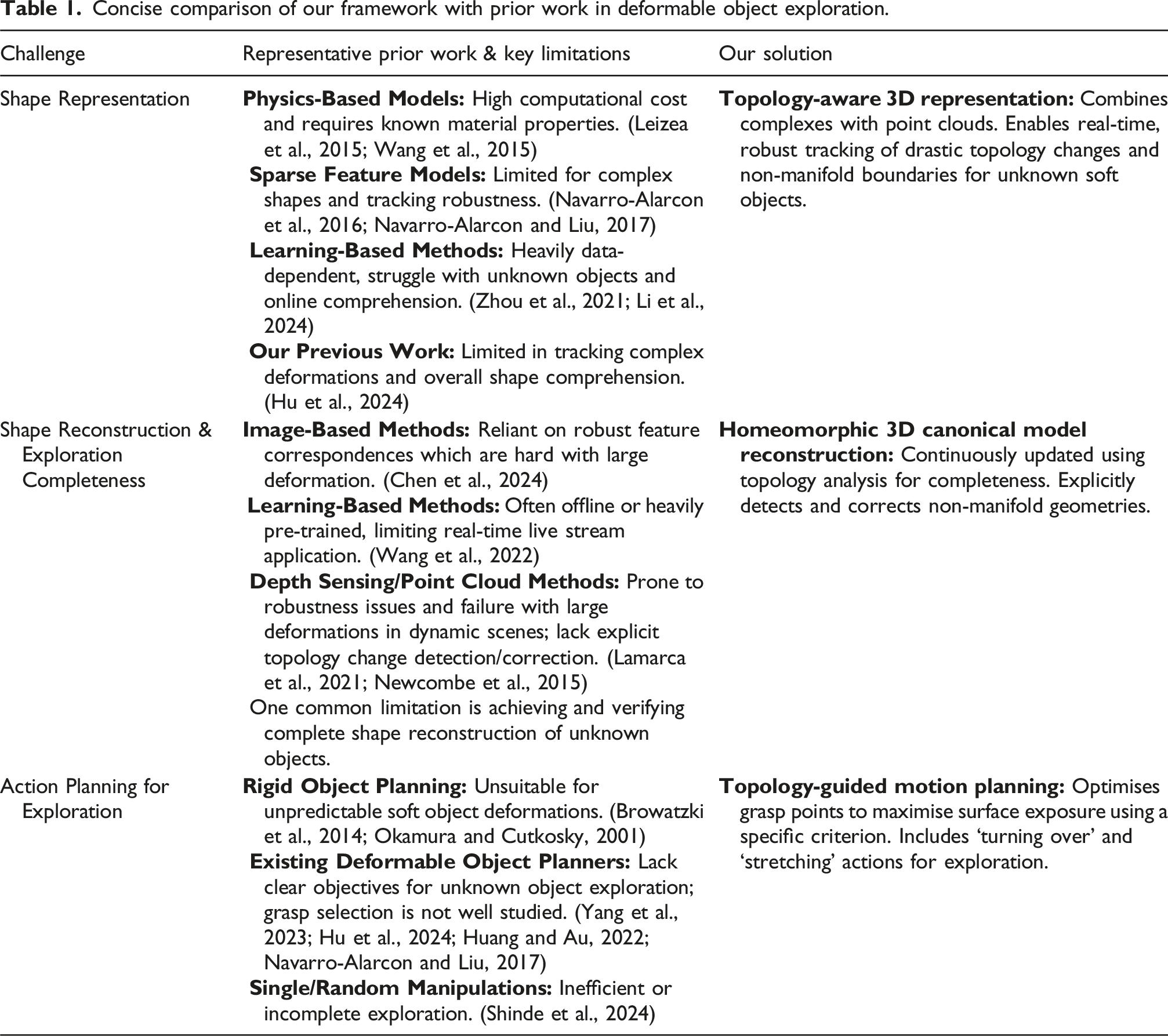
While there has been extensive research on the exploration of unknown rigid objects (Browatzki et al., 2014; Okamura and Cutkosky, 2001), to the best of our knowledge, no published work specifically addresses the robotic exploration of soft objects. This paper presents a novel framework for a vision-guided, multi-arm robotic system designed to manipulate unknown soft objects with the goal of fully understanding their shape and texture. The framework integrates perception, analysis, grasp point selection, and trajectory planning. This framework offers novel solutions to these challenges, with its distinct advantages over existing methodologies highlighted in Table 1 and elaborated upon in subsequent sections. The key contributions of this work are 1. A topology-aware representation that extends grid-point-based weighted residual method (GP-WRM) by incorporating topological information is presented, enabling real-time reconstruction and analysis of objects undergoing drastic topological changes during manipulation. 2. Full exploration and homeomorphic reconstruction of an unknown soft object, including complex non-convex and self-occluding features, can be achieved through active robotic manipulation by detecting and revealing previously hidden areas with a small reach. It also mitigates the effects of low-quality point cloud observations and down-sampling. 3. A comprehensive framework for robotic exploration of unknown soft objects, including grasp point selection and trajectory planning, supporting two types of manipulation: turning over and stretching. 4. Validation of the proposed approach through simulations and experiments on various objects, including human cadaveric tissues. Concise comparison of our framework with prior work in deformable object exploration.
Our previous work (Hu et al., 2024) focused on shape control by representing soft objects with the proposed GP-WRM, but faced limitations in completing complex tasks due to a reduced ability to track the deformation field and fully comprehend the overall shape of the soft object. In this work, we extend the deformation representation from the previous study, incorporating knowledge from past deformations to achieve a comprehensive understanding of the geometry, thereby enabling more complex tasks.
Related works
Robotic exploration of soft objects
Autonomous robotic exploration has traditionally focused on understanding environments, such as in the context of drones, service robots (Jiang et al., 2024), field robots (Wettergreen et al., 2005), and underwater vehicles (Mallios et al., 2016). It can also refer to exploring objects within the environment with active interactions, enabling the understanding of mechanical properties and scene graphs. Previous research has used active manipulations to determine boundary constraints in physical models (Boonvisut and Çavuşoğlu, 2014), and to identify parameters for reinforcement learning, allowing robots to manipulate unknown objects more effectively (Schneider et al., 2022). These applications generally rely on rigid objects or static environments, where the robot can infer properties through active interaction with minimal deformation. However, exploring and manipulating soft, deformable objects introduces a higher level of complexity.
In surgical robotics, exploration of soft tissues has been studied. For example, Goldman et al. (2013) proposed algorithms for surgical robots to autonomously explore the shape and stiffness of surgical fields. Shinde et al. (2024) studied active sensing of unknown boundaries, such as tissue attachments, in deformable surgical environments using stereo endoscopic observations. Additionally, haptic feedback systems have been integrated into robotic surgery to provide kinesthetic and cutaneous sensing, allowing surgeons, and theoretically future robots, to directly interpret the mechanical properties of soft tissues (Enayati et al., 2016). However, exploring the complete shape of unknown soft objects remains an open problem, especially in dynamic, deformable environments like laparoscopic surgeries.
Shape representation of soft object
Accurate shape representation is critical in robotic manipulation, allowing the robot to understand and interact with the environment. Early works in the field relied heavily on physics-based models to represent the state of soft objects, including mass-spring systems, position-based dynamics, and continuum mechanics, including finite element methods (FEM) (Yin et al., 2021). FEM provides a detailed representation of soft object deformations (Leizea et al., 2015), but its high computational overhead limits real-time application, prompting the use of linear FEM as a simplified, though less accurate, alternative (Wang et al., 2015). Position-based dynamics, a mesh-free method, has gained popularity for real-time applications, enabling the modelling of dynamic deformations, plasticity, fluids, and rigid bodies (Macklin et al., 2014; Tang and Tomizuka, 2022). When the shape of the soft object is known, estimating the stress or strain fields and deformation can represent its real-time state using non-rigid structure from motion in image modalities (Badias et al., 2021). These methods generally balance computational efficiency and flexibility, making them well-suited for certain manipulation tasks. However, in real-time robotic control, particularly with unknown soft objects, physics-based models often fall short due to the difficulty of establishing mechanical properties in advance.
To address these challenges, some approaches have shifted toward simplified, mechanics-free representations that focus on extracting key geometric features, as an elaborate representation is not necessary for certain tasks. Sparse explicit features provide economical shape representation, including landmarks or geometric features (Navarro-Alarcon et al., 2014, 2016), Fourier surfaces (Kelemen and Gerig, 1996), contours (Navarro-Alarcon and Liu, 2017), latent topology (Zhou et al., 2024), and latent manifolds (Koganti et al., 2017). While these methods are faster and less computationally intensive, they are limited in handling more complex shapes. Additionally, the robustness of tracking algorithms remains a significant challenge.
Integrating these features within point cloud representations of the surface is an alternative technique commonly used in simultaneous localization and mapping (SLAM) problems in deformable environments (Song et al., 2018). More recently, our work proposed an efficient, mechanics-free state, utilising a down-sampled grid of surface points to represent the object’s instantaneous shape (Hu et al., 2024). Modal graphs have been introduced to capture low-dimensional deformation features from raw point clouds while preserving the robotic system’s spatial structure (Yang et al., 2023). These methods represent a promising direction for reducing the computational burden. Still, they are limited in handling extended time periods and complex cases, such as drastic changes in topology due to interactions. Overall, this limits their usefulness to basic shape control operations.
High-dimensional features extracted from big data, such as images or point clouds, are another alternative. Methods like PointNet (Qi et al., 2017) provide semantic understanding of scene features, enabling the identification of 3D objects and their components. Others have relied solely on predetermined, end-to-end pipelines in deep learning, bypassing the need for intermediate representations. These methods often overlook the semantic significance of internal features, thereby failing to provide a comprehensive interpretation of the analytical process (Matas et al., 2018). A more efficient approach uses semantically meaningful lower-dimensional space, or latent shape. Such methods have shown promise in capturing key features of the soft object through data training (Zhou et al., 2021). Latent features can also be integrated into other volumetric rendering techniques, such as neural radiance fields (NeRF), allowing for deformability (Li et al., 2024). However, a limitation of these learning-based approaches is their high dependency on datasets to provide prior understanding and generalisation ability for unfamiliar objects, which presents challenges for online comprehension of unknown objects.
These representations are inadequate for the demands of autonomous robotic exploration. Transitions between visible and invisible surfaces frequently occur, with topology changes over time causing features to disappear and reappear. Consequently, the representation’s effectiveness depends on the observations.
3D non-rigid reconstruction
3D non-rigid reconstruction refers to capturing the shape and appearance of deformable objects and representing them in 3D space. Like rigid reconstruction, various methods can be employed depending on the modality of source data, which includes images, depth sensing, and point clouds.
For image-based methods, non-rigid structure from motion (NRSfM) (Parashar et al., 2019; Torresani et al., 2008) is commonly used to generate a sparse reconstruction and estimate camera motion. This process is followed by multi-view stereo (MVS) (Wen et al., 2019) for detailed reconstruction. Both approaches fundamentally depend on establishing correspondences across images, often achieved using feature detection techniques such as SURF (Bay et al., 2006) or motion tracking methods like scene flow (Chen et al., 2024). In recent years, learning-based methods have been introduced to assist in building correspondences for registration. NeRF can reconstruct 3D scenes from 2D images using volumetric representation (Wang et al., 2022) but is an offline model requiring extensive time to train the neural network, making it unsuited for the real-time reconstructions needed for robotic control. In contrast, our definition of real-time reconstruction focuses on the ability to continuously update the 3D canonical model during ongoing robot manipulation, providing immediate feedback for control actions without requiring the robot to stop and wait for a complete model to be built.
Advances in depth sensing have facilitated 3D reconstruction across various applications, primarily using point clouds often combined with RGB texture. This process typically involves non-rigid registration to align point clouds captured at different times. For dynamic reconstructions, methods aim to align sequential, temporally-spaced point clouds but face robustness issues in highly dynamic scenes (Newcombe et al., 2015). Feature-based representations, like curvature, can enhance performance in these scenarios (Sharp et al., 2002; Tajdari et al., 2022). To handle highly dynamic cases more effectively, topology-aware methods have been developed (Zampogiannis et al., 2019), and using shape templates has been shown to improve non-rigid registration (Lamarca et al., 2021). These methods often solve complex optimisation problems to fit deformation models to the observed data, with the goal of minimising the difference between the captured data and the reconstructed model. A globally optimal solution for deformable SLAM has also been proposed (Bai et al., 2024). However, while these approaches are promising for offline reconstruction tasks, real-time 3D reconstruction remains challenging.
In robotic exploration, where instantaneous decision-making is essential, current methods often fail to achieve the real-time performance for effective online robotic control. Furthermore, the capability to address topology changes is critical. However, existing 3D reconstruction approaches are insufficient in detecting and correcting such changes.
Motion planning of robotic exploration
The motion planning for active robotic exploration varies depending on the task, including the selection of manipulation points and motion planning for manipulation.
Identifying suitable grip points is crucial as they serve as the starting point for manipulating deformable objects, with subsequent motion depending on this choice. In robotic exploration tasks involving soft objects, deformation is influenced by the grip point location, which affects exploration efficiency. Some studies focus on finding optimal grip points to achieve a secure hold with minimal force (Nadon and Payeur, 2019). Task-oriented grip point selection has also been studied, with metrics developed to quantify grasp quality (Huang and Au, 2022). However, selecting grip points to maximise exploration time of hidden surfaces remains an open problem.
The actions in motion planning are often closely related to the representation of the environment and the object of interest. Various planners control the shape of deformable objects based on their representations, such as linearisation models (Navarro-Alarcon et al., 2016), physics-based models (Hu et al., 2024) or learning-based method (Thach et al., 2021). Physical interaction between the robot and the environment leads to dynamic planning. A big challenge in active exploration is the absence of a specific target shape or the difficulty in planning a sequence of target shapes, making the optimisation objective for existing methods unclear. As the robot gathers more information about the unpredictable environment, the motion planning often requires updates. Fully exploring a soft object with a single manipulation is difficult, indicating the need for more comprehensive motion planning based on multiple basic manipulations, aligned with the representation of the soft object.
Modelling and problem formulation
In this paper, we focus on achieving a comprehensive understanding of a single unknown deformable object through robotic exploration using position-controlled robotic end-effectors and a fixed camera. The definition of robotic exploration here involves utilising a camera to capture all surface information and concurrently generating a 3D canonical model of the soft object during active robotic manipulation. The canonical model represents the object’s 3D shape (as point cloud, mesh, or other formats) and is progressively updated using sensor data from depth or RGB-D cameras during exploration. This model, initialised from the object’s pre-manipulation state, serves as a reference frame for integrating incremental geometric information, despite the infinite deformation space of soft objects.
Modelling
As shown in Figure 2, the scenario includes a visual-integrated multi-arm robot system and a deformable object Illustration of robotic exploration of a soft object placed on a table, observed by a fixed RGB-D camera. The table plane is defined as 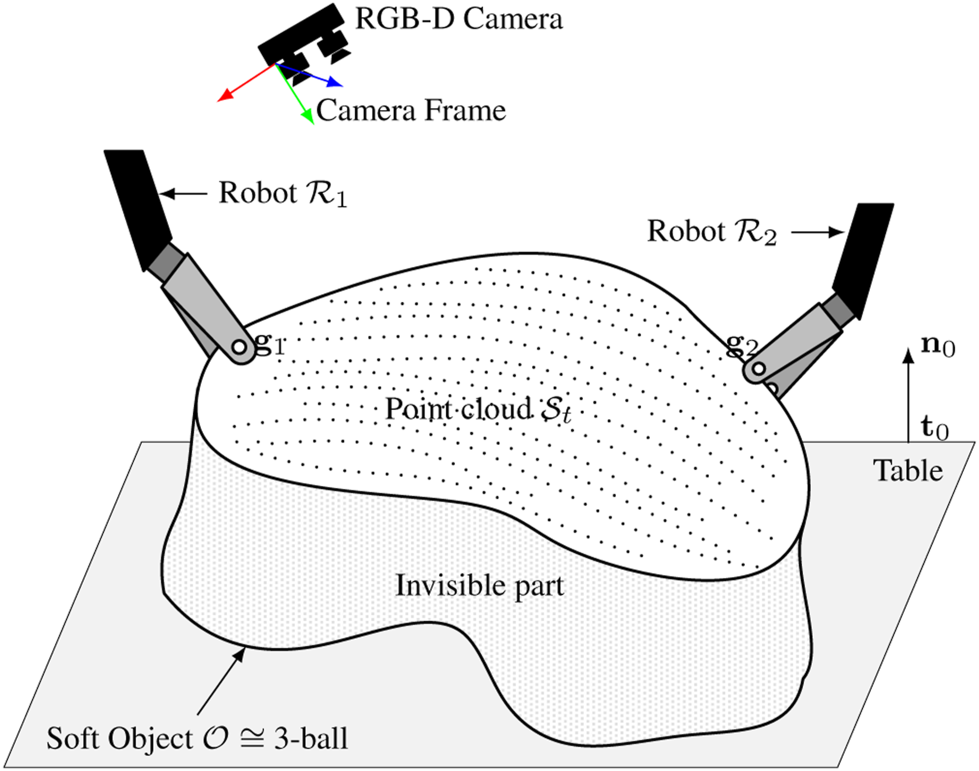
The kinematics of the manipulators are known, and the robot–camera and robot–robot extrinsic relations are calibrated before exploration. In practice, online correction can be achieved using vision-based tool tracking (Hu et al., 2023), which addresses calibration drift in multi-arm systems, especially when passive arms are moved.
There is only one soft object placed on a planar surface, within the workspace of the multi-arm robotic system, and it is not affixed to this surface. The soft object cannot deform without external force.
The camera is fixed in a top-down view relative to the table and the bases of the robots, and it remains stationary during exploration.
Robots have at least 6 degree-of-freedoms (DoF) and can firmly grasp the soft object during the manipulation.
The observed shape of the soft object can be segmented from the raw point cloud captured by the fixed camera.
The soft object is homeomorphic to a 3-ball
1
, indicating that it is solid-core.
Problem formulation
Given an unknown soft object
For simplicity, all positions and orientations discussed in the following sections are referenced with respect to the camera coordinate system, as illustrated in Figure 2.
Overview of the methodology
The workflow of robotic exploration of unknown soft object is depicted in Figure 3. This canonical shape is represented by the 3D canonical model Schematic representation of the proposed controller. The configurations 
Preliminary
Weighted residual method based deformation field
We adopted the GP-WRM method in our previous work (Hu et al., 2024). The deformation field can be discretely described using a set of N deformation nodes
At time t, the positions and displacements of the nodes can be written as 

The normal vector
2D manifold
An unknown soft object can be modelled as a manifold,
The surface of an unknown 3D object is assumed to be a 2D
A camera observing a closed manifold in 3D Euclidean space perceives a subset of
(Camera-Observed Manifold). In camera coordinates, where the optical axis is +z, the portion of the object observed by the camera is defined as:
In practice, the camera-observed manifold is represented by the point cloud Illustration of the case when the reach of manifold is small. The red dashed curve is the observation of the object (black Riemannian manifold). The distance between points A and B (black dots) in observation (yellow arrow) is much shorter than it is in real manifold (green arrows).
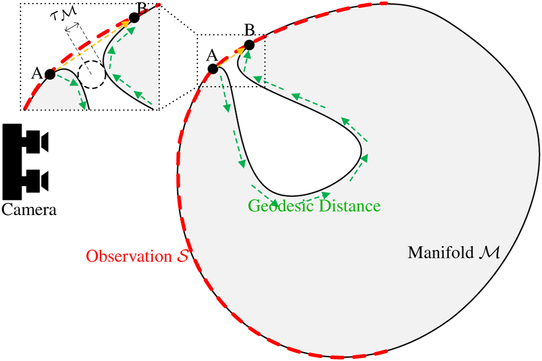
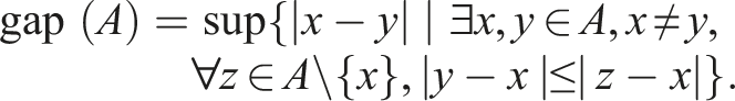
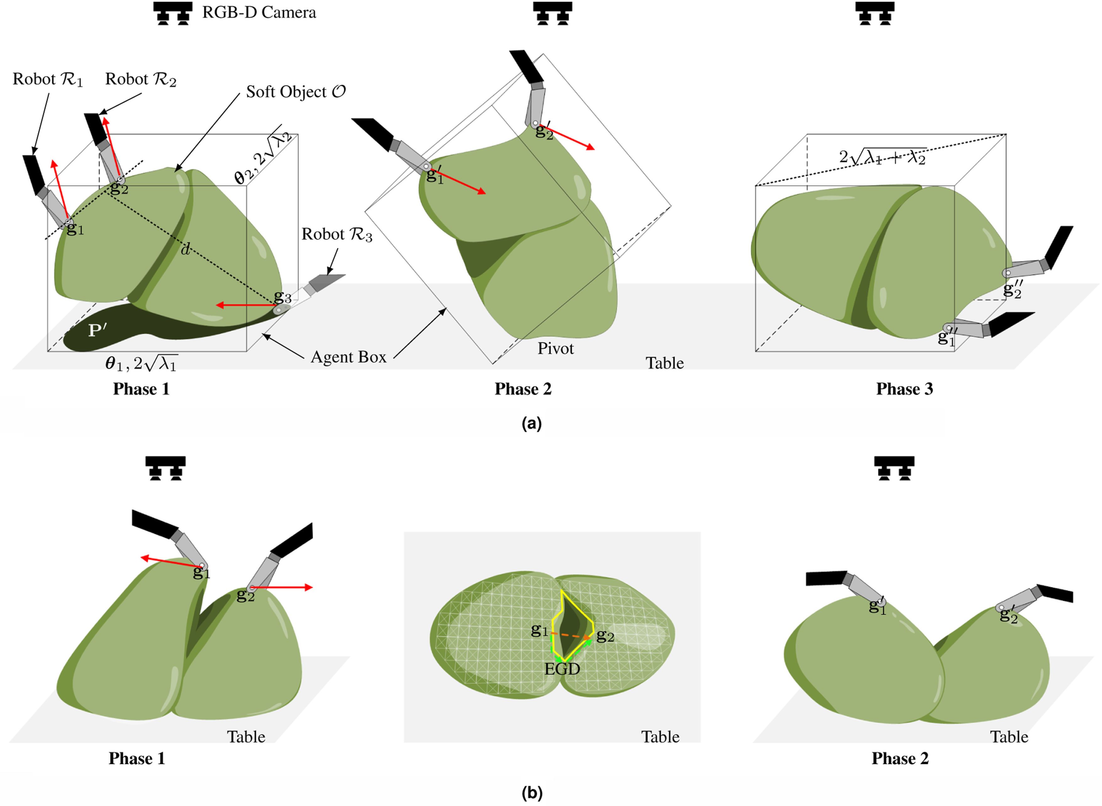
(Estimated Geodesic Distance). The geodesic distance is defined as the length of the shortest path connecting two points on the manifold. The EGD is the shortest distance between two points (more precisely, 0-simplices
5
) passing only through 1-simplices σ1 = {
The topology of a manifold with point cloud observations can be estimated by constructing simplices. Here, we define ‘Distorted Topology’ as the part of the topology that does not fully match the real manifold. Figure 4 illustrates the presence of distorted topology (between points A and B) on the observed manifold
(Distorted Topology). For a 0-simplex in the topology, if the Euclidean distance between its endpoints is significantly shorter than the actual geodesic distance on the manifold, any d-simplices (d ≥ 1) containing these endpoints are considered part of the distorted topology.
Canonical model reconstruction
The reconstruction of the canonical model is illustrated in Figure 5. As manipulations progress, more surface information from the soft object is uncovered. Although the observed surface may differ from the canonical model due to deformation, non-rigid registration allows the observed surface to be fused, resulting in an expanded canonical model. The pipeline for canonical model reconstruction involves the following steps: (1) Establish point correspondences, (2) compute the deformation field, (3) merge point clouds, and (4) update the topology. Illustration of the canonical model reconstruction in sectional views: from t0 to t4, two manipulators (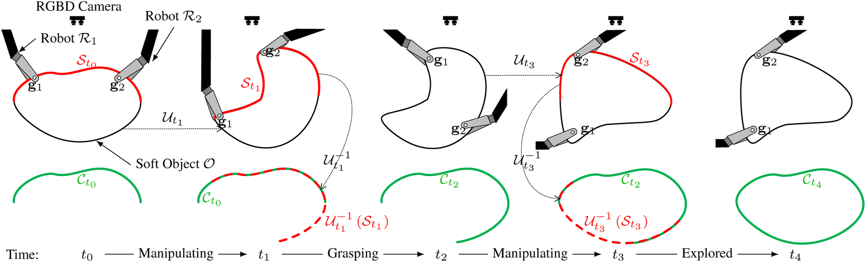
Representation of canonical model and deformation field
The canonical model in this work is represented as a combination of the point cloud and its underlying topology. For each observation with point cloud Illustration of the topology of the observed manifold 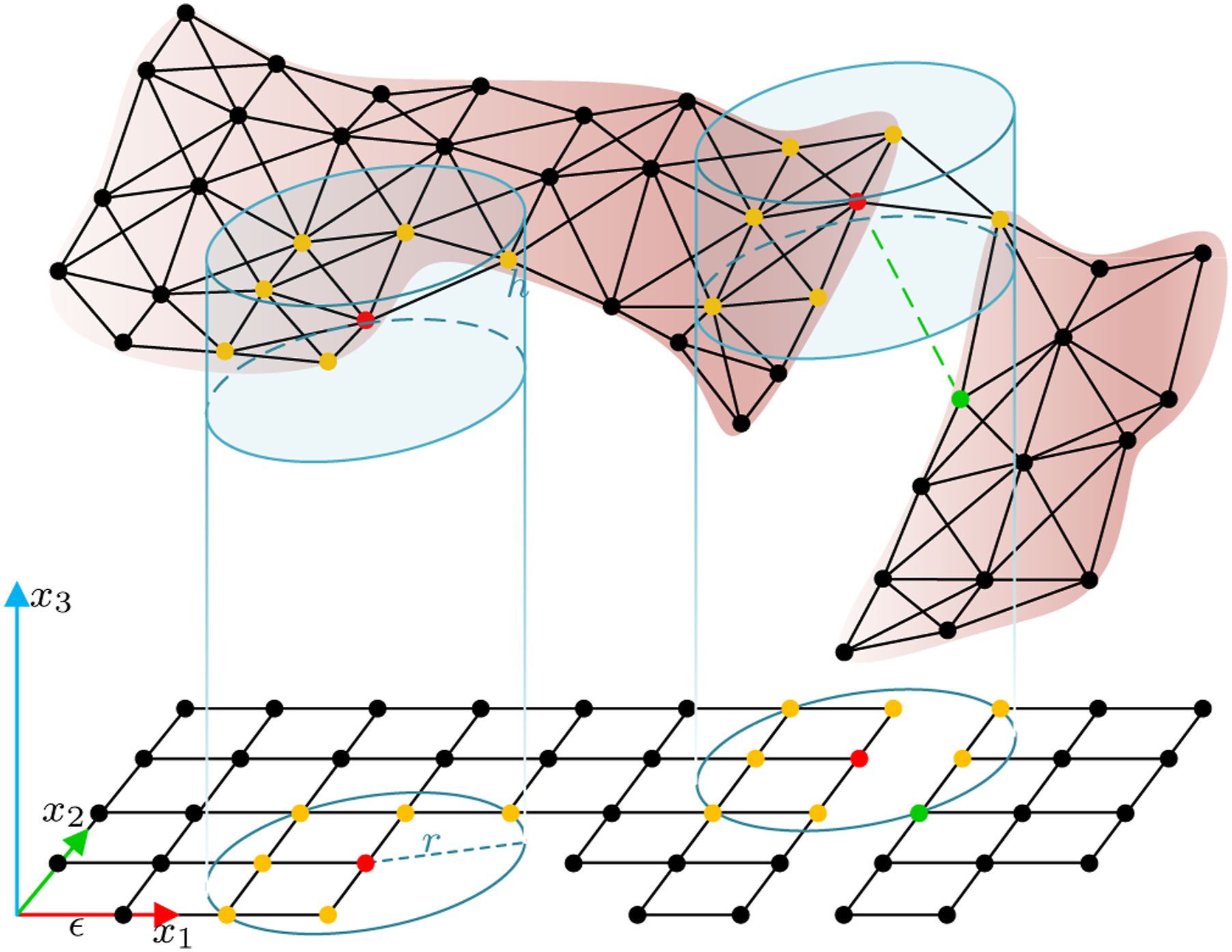
(Cylinder-Čech Complex). Let the (r, h)-cylinder in 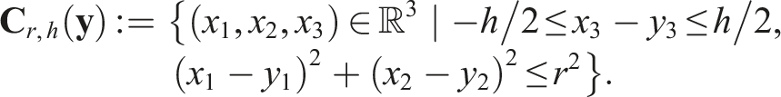
Given a finite point cloud
There only exist d-dimensional (d ≤ 3) simplicies σ for
(Topology Approximation from Depth Map). The topological space of the observed manifold
Lemma 1 demonstrates the selection of appropriate cylinder parameters to reconstruct a representative topology from the sampled point cloud.
For
Since the manifolds are embedded in 

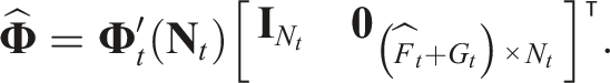
For each 0-simplex, its normal vector is estimated using principal component analysis over the surrounding points. Unlike the Delaunay triangulation, where the normal vectors at the vertices are fixed, the normals in CČC are updated according to equation (5).
The initial canonical model 
Details of these operations are in Appendix C. The accumulated deformation field from the initial state, where 
Measure frame-to-frame deformation
Given the small gripper movement and the presence of specific landmarks that enhance non-rigid registration, the point clouds can initially be aligned using these landmarks. This alignment can then be further refined by establishing correspondences based on the closest points.
The soft object is firmly grasped by the grippers. Consequently, the grip points, whose movements are precisely recorded using forward kinematics, serve as landmarks. The posture of the grippers at time t is denoted as
Utilising feature detection can also rapidly facilitate the generation of landmark correspondences between frames. We use F
t
pairs of corresponding SURF features from sequential frames, denoted as 
The computed displacement of the features will be compared with the displacement estimated from the surrounding points. For any given pair of landmarks 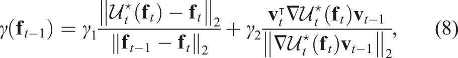
Features with confidence values smaller than threshold will be removed. The remaining features are represented by 
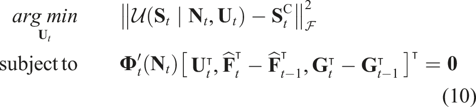
The optimal solution of the problem equation (10) is given by:
The frame-to-frame deformation will be updated as follows: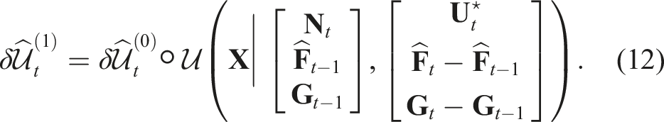
Since the closest points are initially assumed to be the corresponding points, this optimisation needs to be iterated several times, as shown in Algorithm 1. The iteration process continues until the optimal deformation

Invisible topology prediction
The instantaneous diffeomorphism Illustration of invisible topology prediction in sectional views. The curves represent different manifold surfaces. The observation 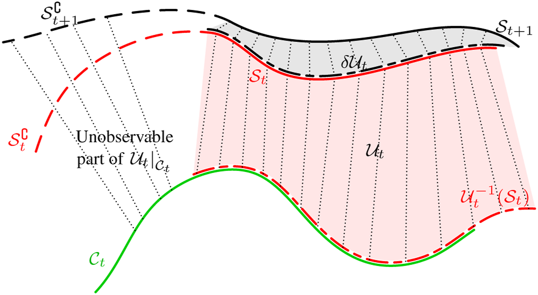
(Singularity in the GP-WRM) (Hu et al., 2024). If the number of the surrounding nodes of a given points is less than 4, the matrix
Lemma 2 demonstrates that not all points in the point cloud can be deformed, as insufficient displacement observations from their neighbouring points lead to a singularity in the matrix
(Observability Matrix for Deformation on a 2-Manifold). After each measurement at time t, let the number of 0-simplices in the canonical model be denoted as Q
t
, and the number of observable vertices as 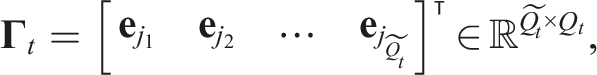
where
The deformation of the canonical model using the observable part is given by
When the rank of the observability matrix
To estimate the diffeomorphism 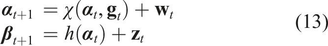

For the state of the system, there are some space constraints for the topology like the external table plane, self-interaction of the topology. We use an inequality constraint:
(External Constraints from the Table). Given the table plane function
(Internal Constraints from Topology Self-Intersection). Let the set
At each time step, the predicted state estimation is 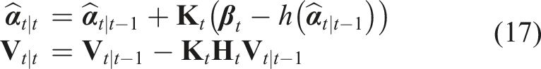
When the inequality constraints (equation (16)) are applied, the Kalman gain
Therefore, the diffeomorphism 
Homeomorphic reconstruction
In Section 5.2, we discussed that point cloud observations might not accurately reconstruct the topology. Lemma 3 establishes the existence of non-manifold (NM) geometries (Definition 6) on the distorted topology using CČC, which can be identified as per Corollary 1. During exploration, however, observations with a small reach τ may undergo deformations, potentially uncovering the true topology, as demonstrated by Lemma 4. Thus, homeomorphic reconstruction of the manifold can be achieved after appropriate manipulations, accurately reflecting its true topology through the reconstructed canonical model.
(Non-manifold Geometry). A d-manifold
(Existence of Local Non-Manifold Geometries). Consider a manifold
The neighbourhood of σ0 is denoted as B
r
(σ0), which is a ball of radius
(Detection of Non-manifold Geometries). Given the topological space of

According to Lemma 3,
(Full Observability of a Manifold). Given any 2-manifold
The diffeomorphism map, also known as the deformation field, is continuous due to the physical properties of the soft object. According to Lemma 1, NM geometries can be detected when 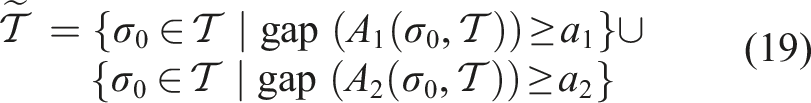
Two metrics for measuring the difference between two displacements are the Euclidean Distance (A1) and Cosine Similarity (A2).
The simplices containing the 0-simplices in the NM topological space
Shape merging
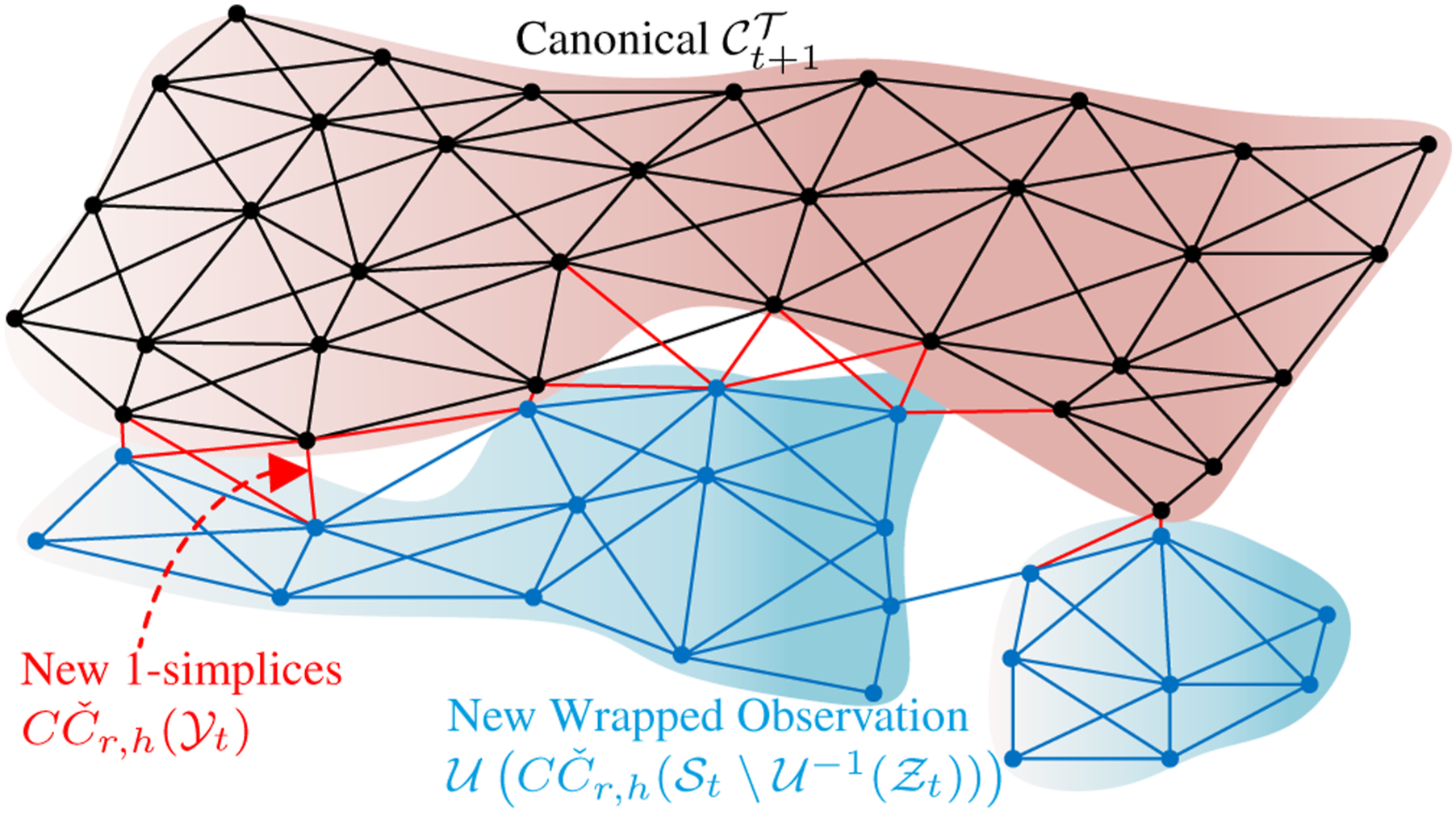
After each observation 
Directly merging two surfaces may result in overlapping layers, and as additional wrapped point cloud surfaces are introduced, the point cloud of the canonical model may get unclear, hindering further non-rigid registration. To address this, moving least squares (MLS) method (Alexa et al., 2003) to smooth the surface, using 0-simplices as nodes, is applied. Based on equation (20), the new canonical model is
For topology merging, in the first frame, the canonical topology directly adopts the topology of Topology Merge: The black, blue, and green meshes represent the topological spaces of the canonical model, newly wrapped observation, and new 1-simplices.
Planning of grip points
In this section, the selection of grasp points is introduced. Before the soft object is fully explored, the canonical model
Candidate grip points
As illustrated in Figure 9, the workspace Illustration of the workspace for a three-arm robotic system. The blue areas represent the workspace of each arm.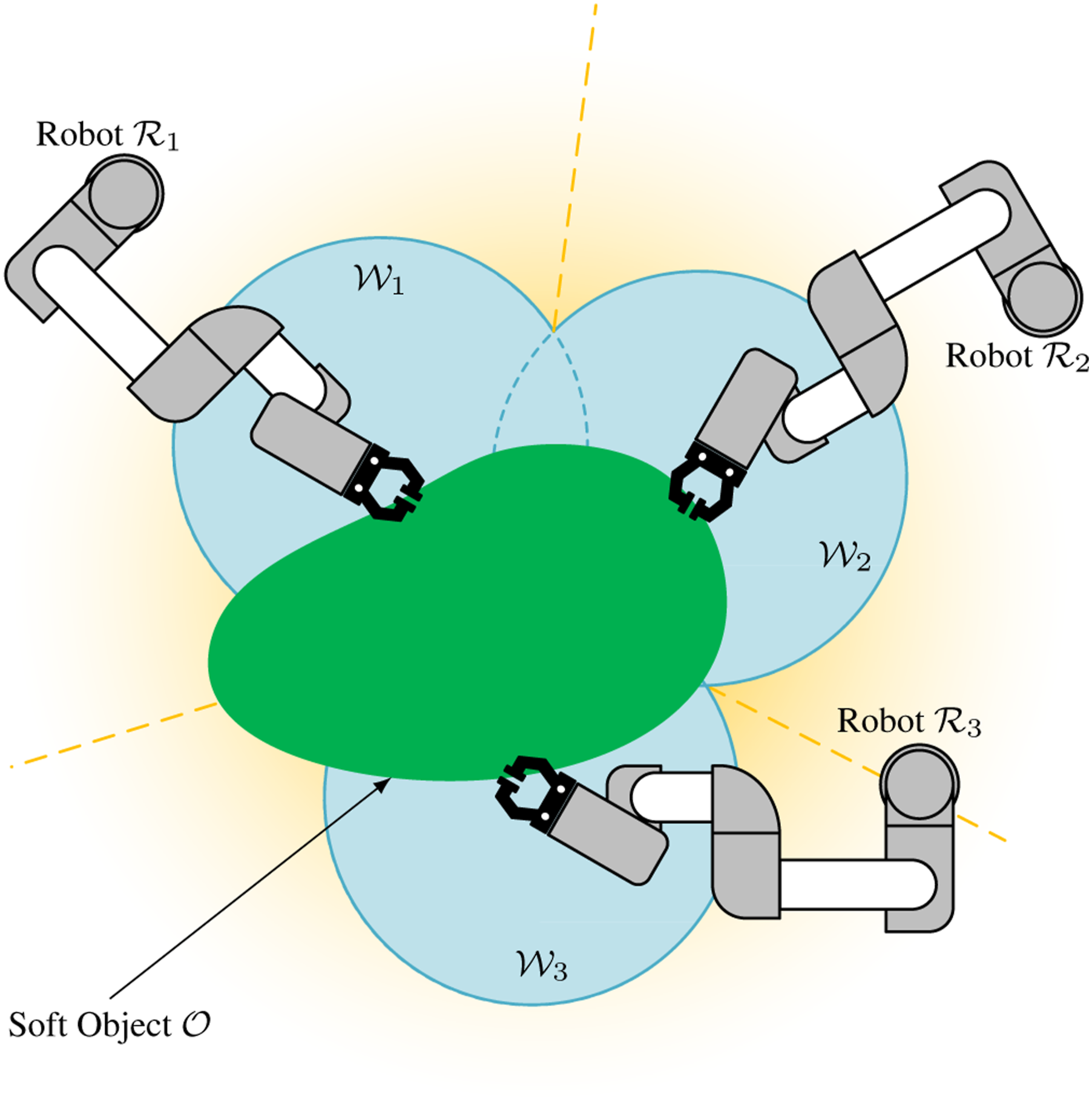
The candidate grip points 
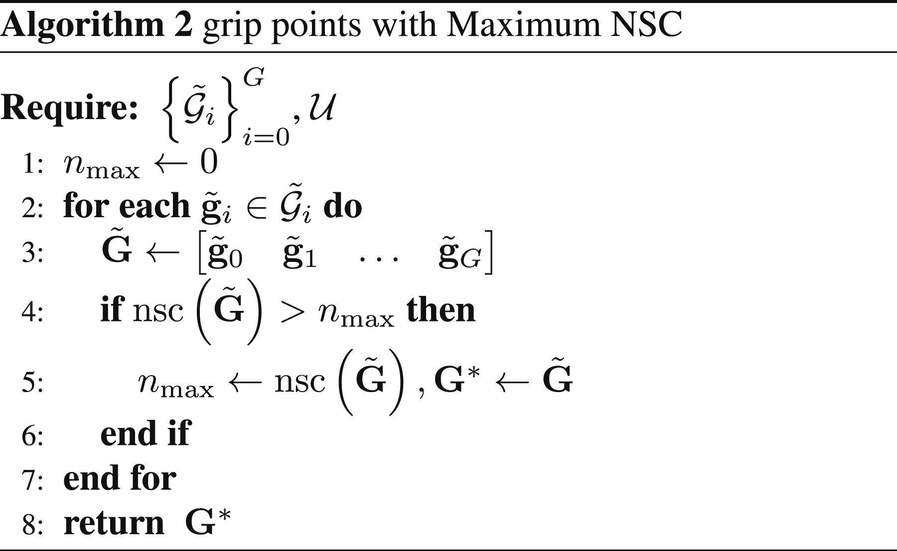
Optimal grip points based on null space analysis
Since the grip points are also on the surface, utilising the deformation field in equation (1), the relationship between the movement of the manipulation points and the displacement field is (Hu et al., 2024):
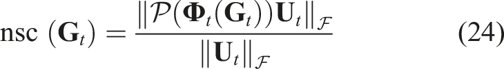
To find the optimal grip point 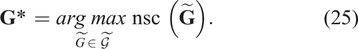
The details are shown in Algorithm 2.
However, limitations arise because certain points on the boundary of the canonical model may be physically unreachable for the manipulators. For instance, the gripper might be obstructed by the soft object itself when attempting to approach a target located beneath it.
Orientation of grasping
The pitch of the gripper at the grasp point is determined by the normal vector 
Motion planning
The goal of motion planning is to orient the invisible portion of the surface toward the camera, thereby enabling closure of the canonical model. Once the grasp points are determined, the corresponding trajectories and motions of these points must be precisely planned.
The procedure of robotic exploration is iterative. Before each iteration, the grippers are homed to minimise occlusion. Then the grippers move toward the designated grip points and securely grasp the object. Two manipulators serve as the primary actuators, while any additional arms, if available, provide support during manipulation. To avoid collisions between the manipulators and the soft object during manipulation, the orientation of the gripper is adjusted first, followed by the translation of the gripper. Based on the analysis of the topology of the wrapped canonical model, the actions are categorised into two types: turning over and stretching. The exploration process continues until the stop condition is met, as illustrated in Figure 10. Schematic representation the motion planning.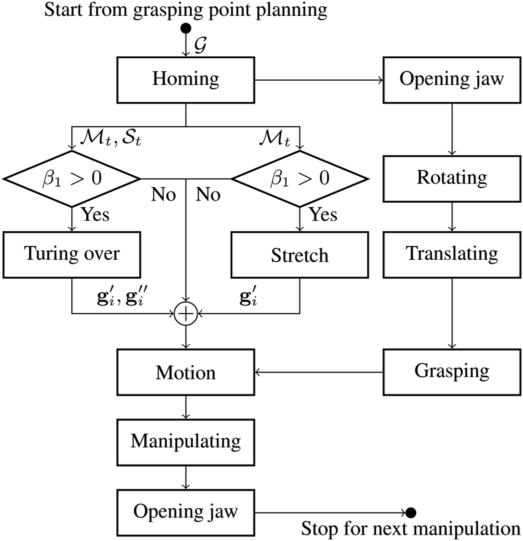
Topology analysis with Betti number
Motion planning is based on the shape of
For a given topological space
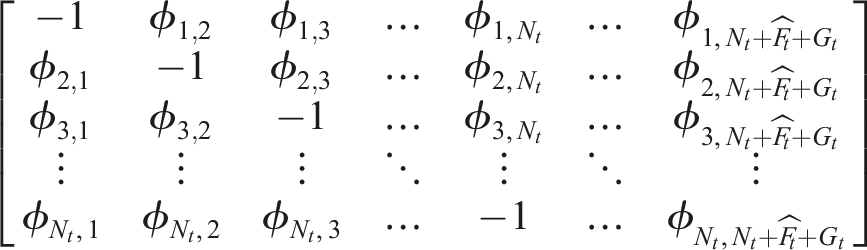
The identification of Betti numbers is based on constructing the boundary matrix
Given that computing Betti numbers incurs higher computational costs as the topology becomes more complex, this computation is performed only before each manipulation.
Stop condition
According to Assumptions 2 and 6, when the surface of the canonical model is closed, for a volumetric object, its Betti number sequence is
Trajectory planning
The control of soft objects varies depending on the configuration of the robots and the properties of the objects. Unlike traditional manipulation planning for rigid objects with high stiffness, we propose a generalised trajectory planning approach for robotic exploration and manipulation of soft objects. This approach includes actions such as turning over and stretching.
Turning over
In most cases, the hidden portions of the soft object are typically oriented downward, making it essential to turn the object over to explore these invisible areas. This action involves using a pivot to reverse the orientation of the soft object.
As shown in Figure 11(a), since the explored soft object has infinite DoF and is predicted to deform, an agent box is used to efficiently describe the shape of the wrapped canonical model Illustration the trajectory planning during the manipulation. The green object represents the soft object, and the red arrows are the trajectory directions. (a) Turning over. When a third arm is not available, the friction between the soft object and the table serves as the pivot. (b) The middle image shows the camera view of the soft object in Phase 1. The yellow loop indicates the 1D holes in its topology (white mesh). The green dashed arrows represent the EGD from 
When G = 3,
There are two stages for the turning operation: In the 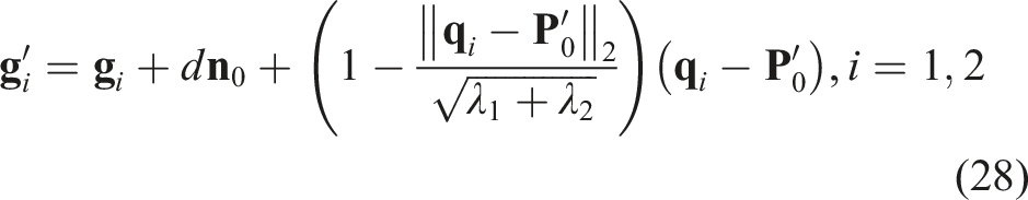
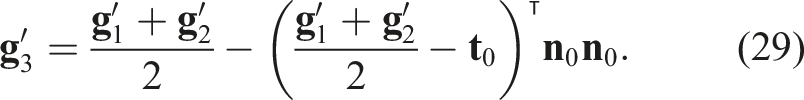

When the number of manipulators is limited to two (G = 2), the edge or friction between the soft object and the table serves as the pivot, as shown in Figure 11(b).
Stretching
Folds on the soft object can create additional hidden areas, particularly in depressed regions, which necessitates the use of a stretching operation. The invisible depressed areas are represented as 1D holes in the topology of
The stretching operation is based on the EGD on 
When the conditions for both turning over and stretching are met simultaneously, the stretching can be incorporated directly into equations (28) and (30) directly.
Manipulation speed
According to equation (23), the displacement of the grid points after the movement of the grip points is expressed as:
Due to the initial lack of deformation information during manipulation, the manipulation speed begins slowly and then gradually increases. Subsequently, the deformation 
Therefore, the maximal manipulation speed is limited at
Simulated validation
The simulated validation was carried out using the SOFA framework (Faure et al., 2012). In the simulator, the geometry of initial 3D model is known and can be regarded as the ground truth (GT) of the reconstructed canonical model. During manipulation, the positions of each vertex and the movements of the robots can also be recorded. To simulate the point cloud from the camera perspective, the vertices on the mesh facing the virtual camera serve as the point cloud 
In this simulation, to provide a more intuitive result, we presented the relative measurement of reconstruction error and prediction error relative to the size of the canonical model, which is approximately
Simulations on liver model
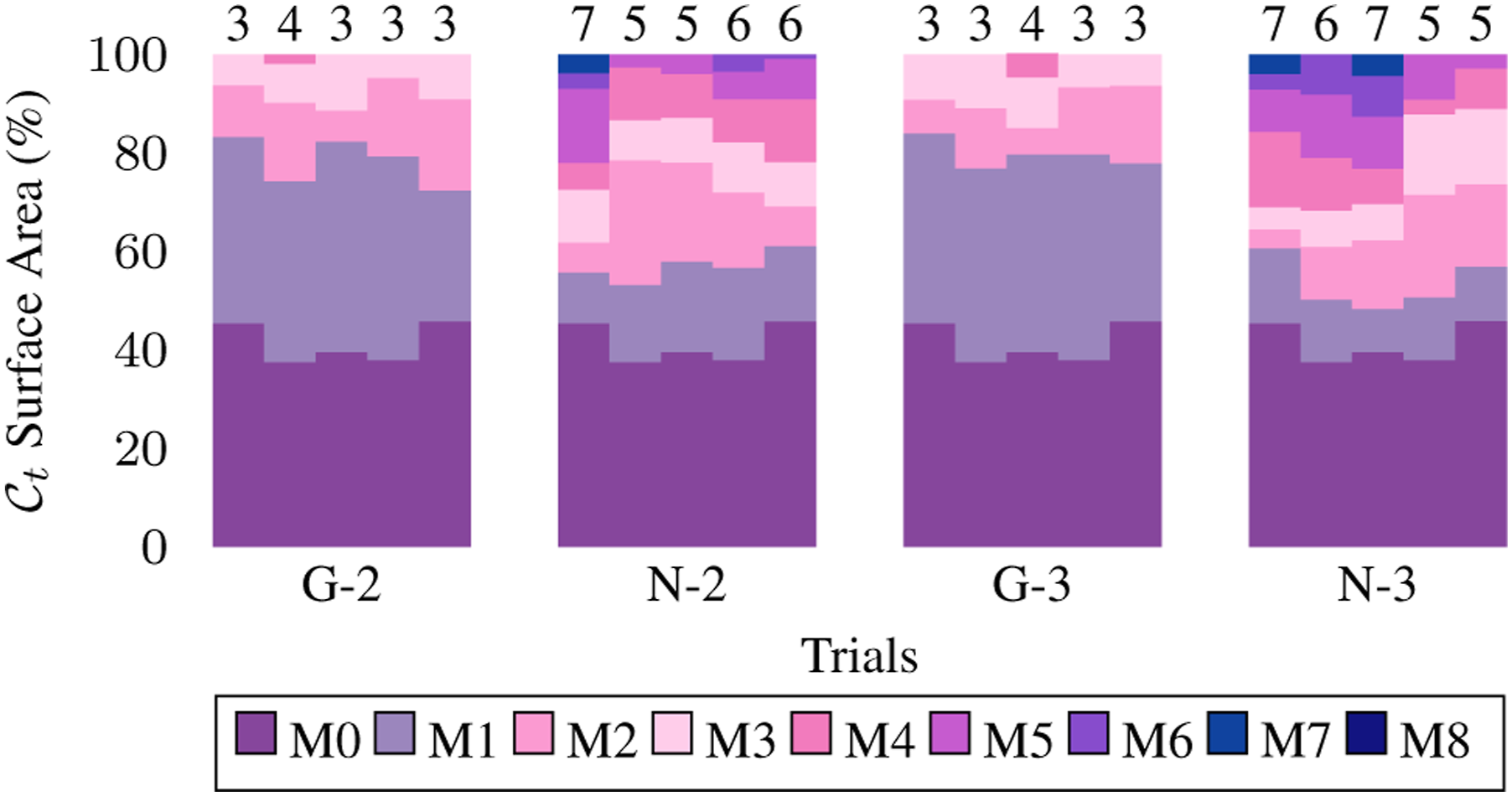
We employed a 3D liver model as the soft object, specifying the Young’s modulus of 500 N m−2 and Poisson ratio of 0.3. The liver model has 2194 vertices and 4385 triangles. It was placed on a table whose plane function is defined as Simulation of robotic exploration of a 3D liver with three arms. Upper: The first row shows the SOFA simulator, with green points representing the observed surface. The second and third rows display the camera view and side view of the canonical model, respectively. The fourth and fifth rows show the topology from two different perspectives. Lower: The plots illustrate the canonical surface area, canonical shape difference, and prediction error throughout the robotic exploration. Explored surface area percentage before each manipulation across tasks. Groups G-2 and G-3 represent simulated tasks with grip point planning using two and three arms, respectively, while N-2 and N-3 represent tasks without planning. M1 to M8 indicate the increase in reconstructed area percentage after each manipulation, with M0 showing the initial percentage. The number atop each row denotes total manipulations performed.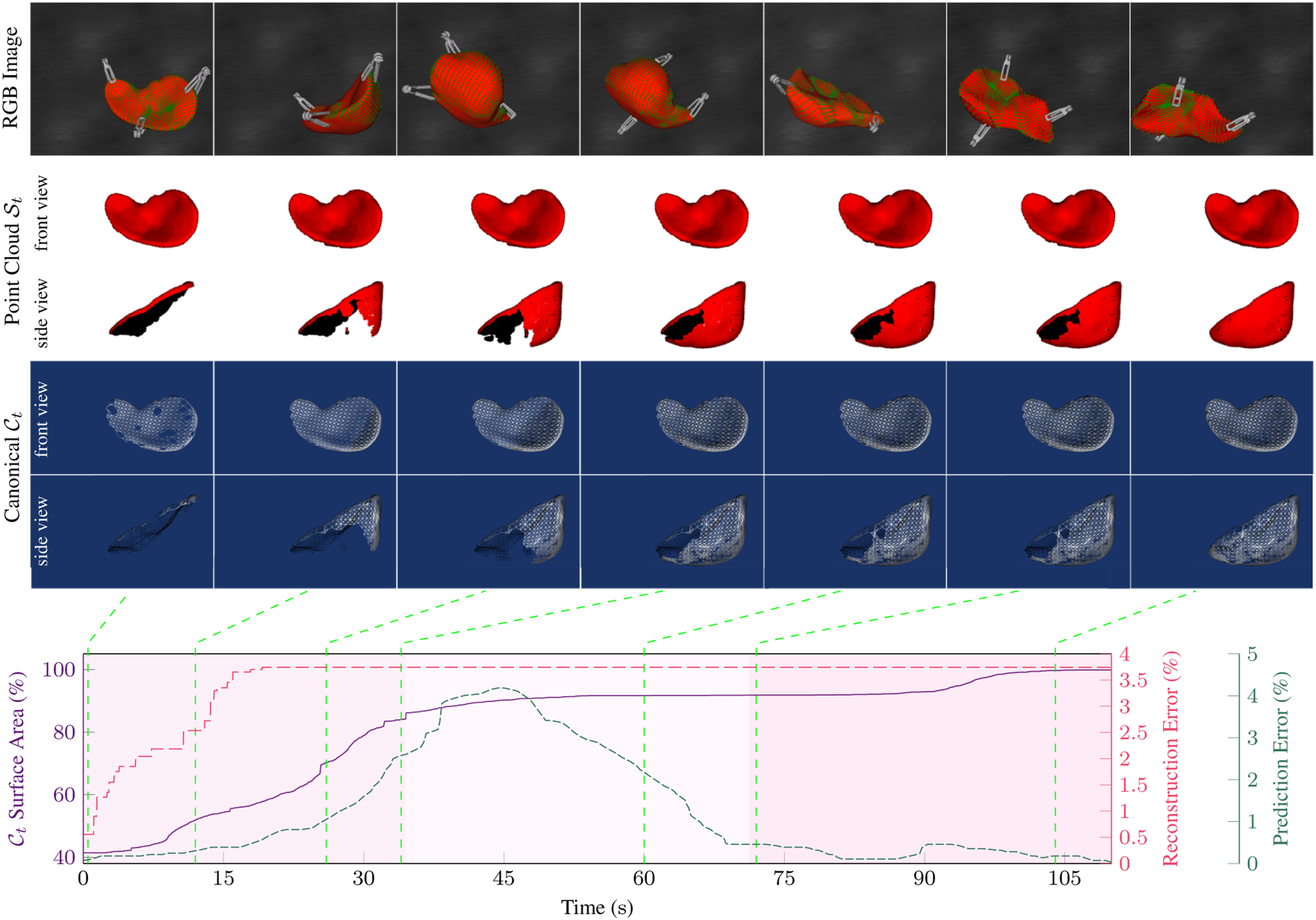
To avoid the influence of collisions between the grippers and the liver during the homing and reaching procedures to the grip points, these steps are simplified. In the simulations, the virtual grippers are positioned directly at the optimal grip points once determined, and only the manipulations are simulated.
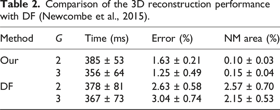
Comparison of the 3D reconstruction performance with DF (Newcombe et al., 2015).
Comparative studies
Effect of the sample rate
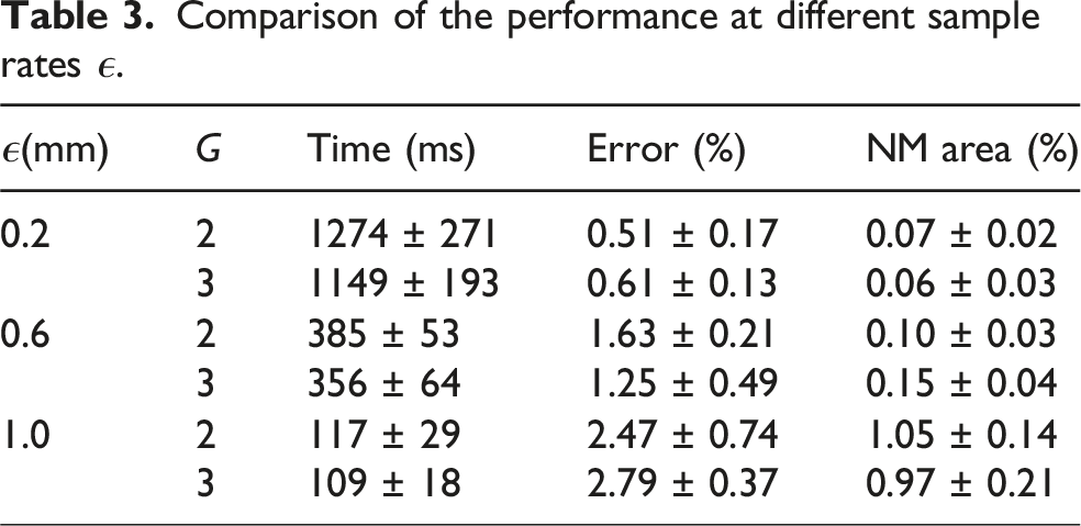
Different sampling parameters were selected to validate the effect of the sample rate. In each simulation configuration, we used three levels of the sample rate, ϵ = 0.2 mm, ϵ = 0.6 mm, ϵ = 1.0 mm. All three groups were carried out five times with different initial poses. The shape difference between the reconstructed canonical model and the GT, the NM area, and the average registration time were measured.
Comparison of the performance at different sample rates ϵ.
Effect of the grasp point planning
To demonstrate the effect of grasp point planning, we conducted experiments where the grip points were randomly selected on the boundary
Figure 13 compares the number of manipulations and the explored area of the canonical model between methods with and without grip point planning. The results show that random grip point selection requires more manipulations to complete the exploration. On average, 5.8 manipulations are needed with two arms and 6.0 with three arms. In contrast, with our method, the average number of manipulations needed is just 3.2 for both configurations. For each manipulation, the average area increase is 9.97% when grip points are randomly selected, compared to 18.38% when grip points are planned based on the NSC.
Effect of the manipulation speed
We also investigated the effect of the grippers’ maximum speeds vmax, in equation (34), during the manipulation in the three-arm configuration, using 10 different maximum speeds ranging from 0.1 mm s−1 to 10 mm s−1. In each manipulation, the grip points remained the same as those used for grip point planning at 0.1 mm s−1. In these experiments, the frequency of image and point cloud recording was consistently set at F = 10 Hz. Reconstruction errors, prediction errors, and total exploration time were measured in these simulations, as shown in Figure 14. Effect of different maximal manipulation speeds vmax on reconstruction error and prediction error. The red cross mark indicates cases where the exploration was failed.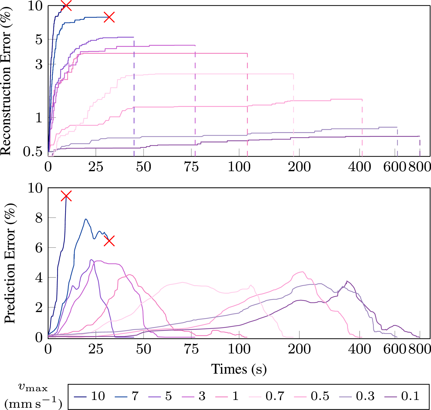
When the maximum manipulation speed increases, the total exploration time decreases, but the reconstruction error increases as the difference between two sequential frames becomes larger. The results show that excessive speed reduces the success rate of frame-to-frame registration, increasing the risk of exceeding the registration error threshold. In this simulation environment, reconstruction fails when the maximum speed surpasses 5 mm s−1. To ensure successful exploration, the deformation threshold must satisfy
Experimental validation
Experiment setup
As shown in Figure 15, we use the da Vinci Research Kit (dVRK) (Intuitive, USA) (Kazanzides et al., 2014) for validation, consisting of two patient-side manipulators (PSM). A fixed RGB-D camera (RealSense, Intel, USA) is utilised to capture the surface and texture information of the explored soft object. Experimental setup.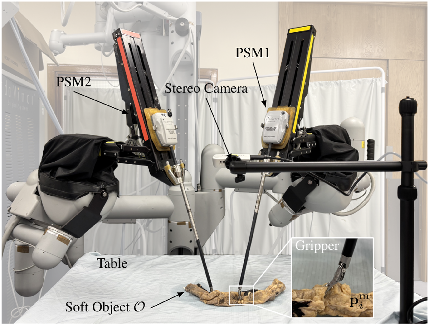
The soft objects (rubber glove, beanie, colon, and liver) were placed on a table at a known position relative to the camera and manipulated by two 7-DoF PSMs. The Point Cloud Library (PCL) (Rusu and Cousins, 2011) was used for filtering the point cloud and computing features. The point cloud corresponding to the table was removed using a plane function, while the point cloud associated with the PSMs was excluded using kinematic data.
Two soft objects made of different materials and shapes (a rubber glove and a beanie) were used as they are commonly found in daily life. To validate the procedure in the context of RAMIS, cadaveric colon and liver tissues were used to replicate common scenarios in laparoscopic exploration. These experiments, including those on cadaveric tissues, aim solely to validate our general robotic exploration techniques for soft objects. They are not intended to develop controllers for actual RAMIS procedures, as the real surgical environment, with its need for highly specialised and delicate manipulations (e.g., folding, peeling, localised lifting), presents additional complexities beyond the scope of this foundational exploration framework.
To evaluate the performance of canonical reconstruction on real-world data, we employed a deep learning approach. OmniMotion (Wang et al., 2023) was used offline to obtain dense pixel correspondences. Since analysing long videos with this method requires significant memory storage due to extracting the optical flow and cycle consistency masks between all possible pairs of frames in the videos, we segment the videos into sections by each manipulation (around 45 s) and sampled them at 10 frames per second. This allows us to obtain reliable pixel correspondences in time windows long enough for the exploration. Given the intrinsic and extrinsic camera parameters, along with the depth information from the camera, the corresponding tracked pixels across frames were utilised to reconstruct the 3D canonical model in a point cloud format.
Robotic exploration of rubber glove
In this experiment, a blue rubber glove filled with a substance is employed, with two PSMs manipulating the glove, as illustrated in Figure 16. The parameters for the CČC are set with a radius of 5 mm, and a height of 8 mm. Upper: Robotic exploration of a rubber glove. The first row shows camera images. The second and third rows show the point cloud  represent homing, grasping, and up and down manipulation stages, respectively.
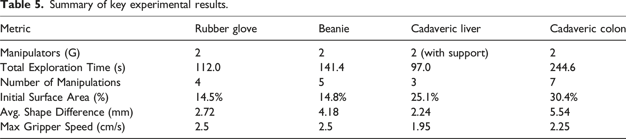
In this case, after four manipulation cycles, the glove was fully explored. As shown in Figure 16, the initial point cloud, captured at t = 0 before exploration, constitutes approximately 14.5% of the canonical model, and the Betti number is
Within four manipulations, the maximum speed of both grippers is vmax = 2.5 cm s−1, with a deformation cap of ξ = 5 mm and a registration frequency of 3 Hz. During manipulation, the average speed of both grippers is 1.84 mm s−1. Approximately 83.2% of the deformation fields between two consecutive frames are smaller than ξ, with an average deformation of 4.54 mm. The average shape difference between the canonical model reconstructed through robotic exploration and the learning-based method is 2.72 mm.
A drastic topology change occurred during the second manipulation phase when the index and middle fingers began to open around t = 37.2 s. Before this, they were considered closed. The NM geometry was detected between the two fingers based on the difference of the displacement, consisting of 23 0-simplices, 18 1-simplices, and 16 2-simplices, as shown in Figure 17. This NM geometry was removed, allowing the correct topology to replace it with new observations. The accompanying video (Extension (2) shows the entire exploration of the rubber glove. Detection of the NM boundary on the topology of the canonical model (indicated by the red dashed line) in the robotic exploration of the rubber glove. The colormap shows the distribution of the Euclidean Distance metric and Cosine Similarity metric as described in equation (19).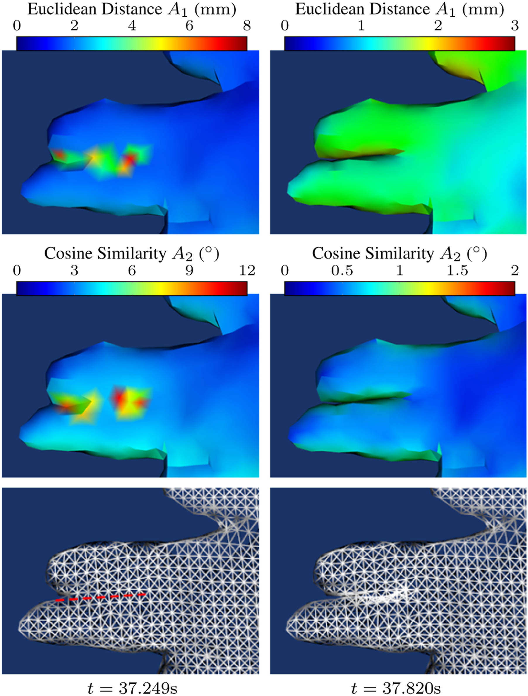
Robotic exploration of beanie
In this experiment, a beanie was used as the soft object. Compared to the rubber glove, it is softer and contains an inner lining. Our method successfully enables robotic exploration of the beanie. The parameters for the CČC are r = 5 mm and h = 8 mm. As shown in Figure 18, the beanie is manipulated 5 times to reach the stop condition. The areas of canonical surfaces before each manipulation are 14.8%, 69.4%, 81.2%, 95.1%, 95.7% and the Betti number sequences are shown in the Table 4. The corresponding Betti number sequences are listed in Table 4. Stretching occurred only during the second and third manipulation phases. At around t = 19 s, the inner lining became visible to the camera, indicated by the emergence of a 1D hole on Upper: Robotic exploration of a beanie. The first row shows camera images. The second and third rows show the point cloud The Betti numbers of the canonical model  represent homing, grasping, and up and down manipulation stages, respectively.
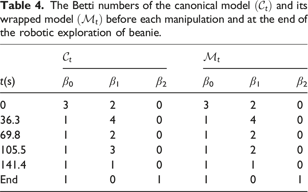
We validated the performance of the constraints in topology prediction. During the robotic exploration of the beanie, the constraints related to the table plane were not applied. Although the beanie was placed on the table, ideally requiring all points The side view of the canonical model at the first and last frames in the robotic exploration of the beanie.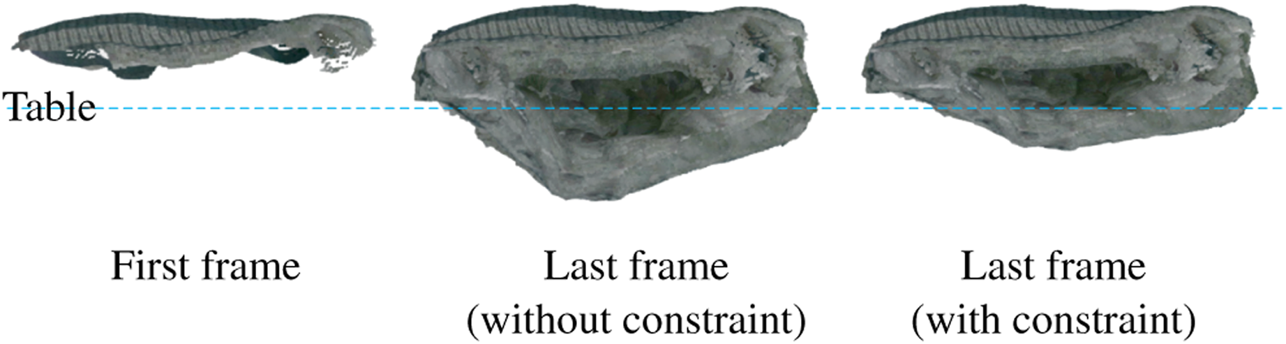
Robotic laparoscopic exploration of cadaveric liver
As shown in Figure 20, robotic exploration of the human cadaveric liver was conducted. Due to the weight of the cadaveric liver, an additional surgical tool was used as a supporting arm for the dVRK. A planar label measuring 15 mm × 80 mm was attached to the liver specimen, and its point cloud was removed to ensure that only the cadaveric liver was reconstructed. Upper: Robotic exploration of a cadaveric liver. The first row shows camera images. The second and third rows show the point cloud  represent homing, grasping, and up and down manipulation stages, respectively.
The liver was manipulated for 3 times to reach the whole canonical model, and all the manipulations were only turning over. In the first manipulation, grip points were selected on the gallbladder and round ligament, taking 27.4 s to turn the liver and expose more of its surface. In this experiment, the initial canonical model is partially occluded by the surgical instrument, with the initial surface area accounting for 25.1% of the final canonical model surface. In the second manipulation phase, the grip points were located on the gallbladder and right triangular ligament. This manipulation increased the explored area from 83.9% to 97.0%. In the third manipulation phase, the grip points were positioned at both ends of the falciform ligament. The maximal speed for two active manipulators in these three manipulations is 1.95 cm s−1.
The average shape difference of the liver is 2.24 mm compared to its reconstruction using OmniMotion. The error is higher in the region around the gallbladder, as this area is softer and more prone to deformation. The accompanying video (Extension 4) shows the entire exploration of the cadaveric liver.
Robotic laparoscopic exploration of cadaveric colon
A human cadaveric colon, approximately 20 cm in length, was used for validation. As shown in Figure 21, a higher resolution of the CČC was set for the colon due to the presence of adhesive fats and folds, with a radius of 3.5 mm and a height of 6 mm. Upper: Robotic exploration of a cadaveric colon. The first row shows camera images. The second and third rows show the point cloud  represent homing, grasping, and up and down manipulation stages, respectively.
The exploration required seven manipulations and 244.6 s in total to complete, starting from 30.4% of the final canonical surface area before exploration. The shape difference between the canonical model and the reconstruction from OmniMotion is 5.54 mm. In each manipulation, the turning-over operations were accompanied by stretching. Throughout the exploration, the rough shape of the colon remained unchanged, resembling a long stick, which resulted in similar maximal manipulation speeds and, consequently, similar manipulation times at 23.72 ± 1.07 s.
In the second manipulation, almost no new surface was explored during the lifting and retracting stages. The optimal grip points were not easily reachable due to partial occlusions that would collapse under the grippers as they approached these points, leading to exploration of new surfaces from these interactions rather than from the turning-over operation. The accompanying video (Extension 5) shows the entire exploration of the cadaveric colon.
Summary of key experimental results.
Discussions and conclusions
Discussion on simulations
The simulations show that the topology-aware 3D reconstruction can not only align different shapes at different times but also reconstruct better topology compared to the point-cloud-based method (Newcombe et al., 2015). This improvement is due to the estimation of topology and the detection of NM geometry. Despite the additional topology estimation, the computational cost remains similar to that of the DF, as using the CČC to estimate topology is efficient. Compared to methods like Delaunay triangulation or the truncated signed distance field (Newcombe et al., 2015), which require mesh compliance checks, this approach is more straightforward. The additional computational cost mainly stems from predicting invisible deformations and merging topologies. The performance of the two-arm and three-arm systems is similar in both operation duration and number of manipulations, as their configurations are nearly identical. The key difference is that the two-arm system relies on friction, while the three-arm system uses the third arm as a pivot. In these simulations, friction is sufficient for turning-over manipulations, with the process primarily dominated by the two active arms.
Several factors affect performance according to the simulations. The sample rate ϵ is crucial, as there is a trade-off between computational cost and reconstruction performance. When ϵ is high, the nodes cannot represent the shape accurately, and the observation is more likely to be non-homeomorphic to the real manifold. Grip point planning can improve exploration efficiency compared to using random grip points. The exploration can be completed with fewer manipulations. This is because grip points with maximal NSC cause more area to be deformed and exposed during the movement of the grip points. When the grip points are randomly selected, the linked area is limited, and the invisible part has a higher possibility of not being indirectly manipulated by the grippers. The effect of the speed is related to the success rate. When the manipulation speed is too high, the non-overlapping area between two frames is small, and its deformation field cannot be directly observed. Therefore, the deformation prediction of the invisible part will be less robust. In extreme cases, the point clouds in two frames do not overlap at all due to fast manipulation, and there is no correspondence between them, leading to failed reconstruction. If the speed is low enough, there is sufficient time for real-time reconstruction, but the exploration time may be too long. The optimal speed in our method balances the trade-off between success rate and exploration time.
Discussion on experiments
The experiments show that autonomous robotic exploration of soft objects with varying materials, shapes, and functions can be completed using our framework for daily and medical applications.
In the glove and beanie experiments, parts of the canonical model appeared below the table, conflicting with the physical expectation that soft objects placed on a table should remain entirely above its surface. This discrepancy arises from relying on visible surfaces for 3D reconstruction, while the invisible portions must be predicted. When large deformations occur, often due to low stiffness or complex geometry, the prediction of invisible topology becomes less reliable, and the assumption of deformation continuity may break down. By contrast, the cadaveric liver, being stiffer and less deformable, produced a canonical model that remained above the table plane during reconstruction. This issue can be mitigated by adding constraints to the EKF when predicting the invisible topology, helping guide the canonical model toward a more realistic initial shape. Still, some regions may appear below the table, since these constraints have limited effect on visible regions where the deformation field is already known.
The robustness of the method relies on the performance of the canonical modelling. In addition to the sample ratio and control speed discussed in the simulation, there are other error sources that affect 3D reconstruction. These include the quality of the point cloud, particularly in the segmentation and reconstruction from the RGB-D image. In the context of robotic surgery, the quality of laparoscopic reconstruction is lower, and the point cloud is sparser in the dVRK system compared to that obtained with a structured-light camera (Chen et al., 2023). While many robotic open surgeries can directly use this technology, better 3D reconstruction methods for laparoscopic images are currently being investigated. Robotic position inaccuracies may disrupt smooth robotic movement, which is crucial for achieving relatively continuous deformation. Continuous deformation helps in predicting invisible parts and thereby improves reconstruction performance. Additionally, the thickness of the soft object influences reconstruction accuracy, as the raw point cloud from the RGB-D camera may not be adequately reconstructed in areas with extremely high curvature. This high curvature near thin regions can lead to discontinuous surface tracking with a stationary camera. In extreme cases, when the soft object is homeomorphic to a 2-disk, the approach may fail.
The planning of robotic trajectory also relies on understanding the underlying topology. The method demonstrates robustness to drastic topology changes, as shown in the experiments on the glove and colon. Misjudgements of topology, which occur when it is not homeomorphic to the actual manifold, often result from the low resolution of the RGB-D camera’s point cloud and the high sampling rate, particularly when the local reach of the manifold is small. As proven in Proposition 1, the true topology becomes apparent as the local reach increases during manipulation. The experiments on the glove and colon have shown that NM geometries can be detected during manipulation. It is important to note, however, that NM geometries may not always be observed unless the required conditions are met through deformation during manipulation according to Lemma 4; otherwise, the controller may never accurately perceive the true geometry. Using the Betti number is an efficient way to understand the overall geometry, but it may be influenced by the quality of the point cloud. The presence of holes or disconnected components in the raw point cloud, caused by environmental lighting or occlusions when using structured light for shape estimation, can lead to β0 > 1 or β1 > 1. However, as more frames are fused, a more complete and accurate canonical model is generated, allowing the Betti number to correctly represent the geometry and enabling the controller to plan trajectories effectively.
This method is also effective for long-term exploration of complex surfaces, as demonstrated in the experiment on the colon. In this case, the controller can operate with a relatively low-resolution point cloud. If the live point cloud and deformation field are stored, a high-fidelity canonical model can be constructed during the intervals between manipulations or afterwards.
Our framework further demonstrates strong robustness to occlusion, despite operating with a single top-down RGB-D sensor. This robustness stems from the shape-control strategy developed in our prior work (Hu et al., 2024), where occlusion-aware down-sampling was used to ensure reliable surface feedback. In the current system, the deformation field computed from this shape controller is further extended into a topology-aware representation. As shown in Figures 16, 18, and 20, the system successfully reconstructs and explores self-occluding objects such as the beanie and cadaveric organs. Occluded regions are gradually revealed and reconstructed over the course of manipulation cycles, enabling complete surface coverage. Furthermore, since our method relies on depth-only input, it is inherently more robust to variable lighting compared to photometric or deep learning-based approaches. This makes our framework particularly suited for surgical environments where visual conditions may be suboptimal.
A key advantage of our method is its model-free design. With non-rigid registration between surface observations, the controller adapts to any source of deformation including breathing, heartbeat, and patient motion without requiring a predefined physical model. This flexibility enhances robustness and applicability in realistic surgical scenarios.
Limitation
First, while our framework’s current ‘turning over’ and ‘stretching’ manipulations are highly effective for the autonomous robotic exploration of unknown soft objects in a general setting, challenges persist for more complex geometries. If the soft object is not homeomorphic to a 3-ball and has a very intricate shape, such as a t-shirt, exploring every part of its surface becomes challenging for the controller due to the lack of prior knowledge about the object’s topology. Specifically, operations like flipping it inside out pose a notable challenge for the robot with our current manipulation set. Additionally, thin soft objects, like planar structures, may not be accurately reconstructed in 3D due to their inherent thinness. Since the behaviour of the object cannot be precisely predicted, for some objects, like cloth, it may become entangled or form a mass after several explorations. Our framework currently does not incorporate more specialised or delicate manipulations, such as localised folding, unfolding, peeling, or precise lifting of small regions. Such operations, while crucial for specific sub-tasks in fields like minimally invasive surgery (e.g., tissue dissection or retraction), fall outside the primary goal of comprehensive surface exploration of an unknown object. Future work will explore integrating these finer manipulation primitives to enhance the system’s versatility for more complex and application-specific tasks, including direct applications to RAMIS.
The current system also assumes that only a single deformable object is present in the workspace, placed on a flat and known surface. This simplification avoids the need for tissue segmentation and recognition, which would be required in more complex settings with multiple or interacting objects, such as surgical scenes. While this limits direct applicability to real surgeries, it allows us to focus on the main contribution of this work, which is the autonomous exploration and 3D reconstruction of soft objects. In actual surgical environments, tissues are often partially attached to surrounding structures, making parts of them physically inaccessible. For example, in the liver experiment, the gallbladder was explored successfully only in its free regions, while the attached areas remained unreconstructed.
The trajectory planning may not be optimal because the optimal grasp points might not be physically reachable. Additionally, the optimal grip points may not suit the gripper due to the stiffness, thickness, and resilience of the soft object in that region. More comprehensive grip point planning, based on properties such as morphology and material, is necessary for more complex tasks and will improve the performance of autonomous exploration.
Another limitation is that the method may be influenced by environmental factors or the specifics of the robotic system. For instance, lighting conditions can affect the brightness of the texture, which impacts both the performance of non-rigid registration and the texture quality of the reconstructed canonical model. This effect is particularly pronounced when surfaces that are initially dark become brightly illuminated as they face the camera. Additionally, different systems have varying manipulator configurations, which can lead to issues such as self-collision.
In real laparoscopic surgery, organs are constrained by ligaments, nerve bundles, and blood vessels that must not be damaged. These connections add complexity to trajectory planning during exploration. Camera movement is also common in laparoscopic surgery, as moving the camera allows for faster exploration of target tissues. Additionally, some of the latest robotic systems, such as the da Vinci 5 from Intuitive Surgical, integrate advanced sensors to restore haptic feedback. This feedback can be analysed to help infer these constraints and improve surgical precision, which is not fully addressed in the current approach.
Conclusion
In this study, we proposed a novel framework for the autonomous robotic exploration of unknown soft objects with 3D reconstruction. The framework integrates topology-aware 3D reconstruction during manipulation with motion planning for robotic exploration. We introduced a novel representation of deformable objects by combining CČCes with point clouds, enabling fast tracking of drastic topology changes and detection of NM boundaries. The motion planning, guided by topology analysis, optimises grasp points and plans trajectories for two types of operations: turning over and stretching. We validated our algorithm through simulations and experiments on various soft objects using the dVRK. The results demonstrate that soft objects can be successfully explored using two or three robotic arms.
In the future, we plan to apply the proposed method to real-world scenarios, such as complete laparoscopic exploration of the small bowel and thin objects.
Footnotes
Acknowledgements
All the experiments involving human cadaveric tissues were performed under ethical approval from the University of Leeds. The authors would like to thank Intuitive Surgical, Inc., for the donation of the da Vinci system, the STORM Lab technician, Samwise Wilson, for hardware support, and the anatomy facilities technicians of the School of Medicine, Sarah Wilson and Charlotte Coleman, for their support in the cadaveric experiments.
Funding
The authors disclosed receipt of the following financial support for the research, authorship, and/or publication of this article: This work was supported in part by the European Research Council (ERC) through the European Union’s Horizon 2020 Research and Innovation Programme under Grant 818045, in part by the Engineering and Physical Sciences Research Council (EPSRC) under Grant EP/V047914/1, and in part by the National Institute for Health and Care Research (NIHR) Leeds Biomedical Research Centre (BRC) (NIHR203331). Any opinions, findings, and conclusions or recommendations expressed in this article are those of the authors and do not necessarily reflect the views of the ERC, the EPSRC or the NIHR.
Declaration of conflicting interests
The authors declared no potential conflicts of interest with respect to the research, authorship, and/or publication of this article.