
Abstract
Dexterous in-hand manipulation offers significant potential to enhance robotic manipulator capabilities. This paper presents a sensori-motor architecture for in-hand slip-aware control, being embodied in a sensorized gripper. The gripper in our architecture features rapid closed-loop, low-level force control and is equipped with sensors capable of independently measuring contact forces and sliding velocities. Our system can quickly estimate essential object properties during pick-up using only in-hand sensing, without relying on prior object information. We introduce four distinct slippage controllers: gravity-assisted trajectory following for both rotational and linear slippage, a hinge controller that maintains the object’s orientation while the gripper rotates, and a slip-avoidance controller. The gripper is mounted on a robot arm and validated through extensive experiments involving a diverse range of objects, demonstrating the architecture’s novel capabilities for manipulating objects with flat surfaces.
Introduction
Humans have the remarkable ability to pick up unfamiliar objects and quickly understand their surface properties, such as friction and dynamics. This knowledge enables us not only to reorient objects using our arms but also to manipulate them within our hands, extending our capabilities beyond what is typically seen in traditional robotics. In this paper, we introduce a sensorized parallel gripper (see Figure 1), for in-hand slip-aware control that relies solely on in-hand sensing. This work is the first to combine both planar velocity and contact forces from independent in-hand sensing modalities for the purpose of slip-aware control in a parallel gripper, introducing new opportunities for intricate robotic manipulation. Each finger is equipped with a commercial 6-degree-of-freedom (DoF) force-torque (F/T) sensor and a custom relative velocity sensor. This hardware combination enables rapid estimation of friction and contact surface properties without the need for external sensors, thus facilitating for precise in-hand manipulation of objects with flat surfaces in both rotational and translational movements.
1
Picture of the custom gripper mounted with F/T and relative velocity sensors.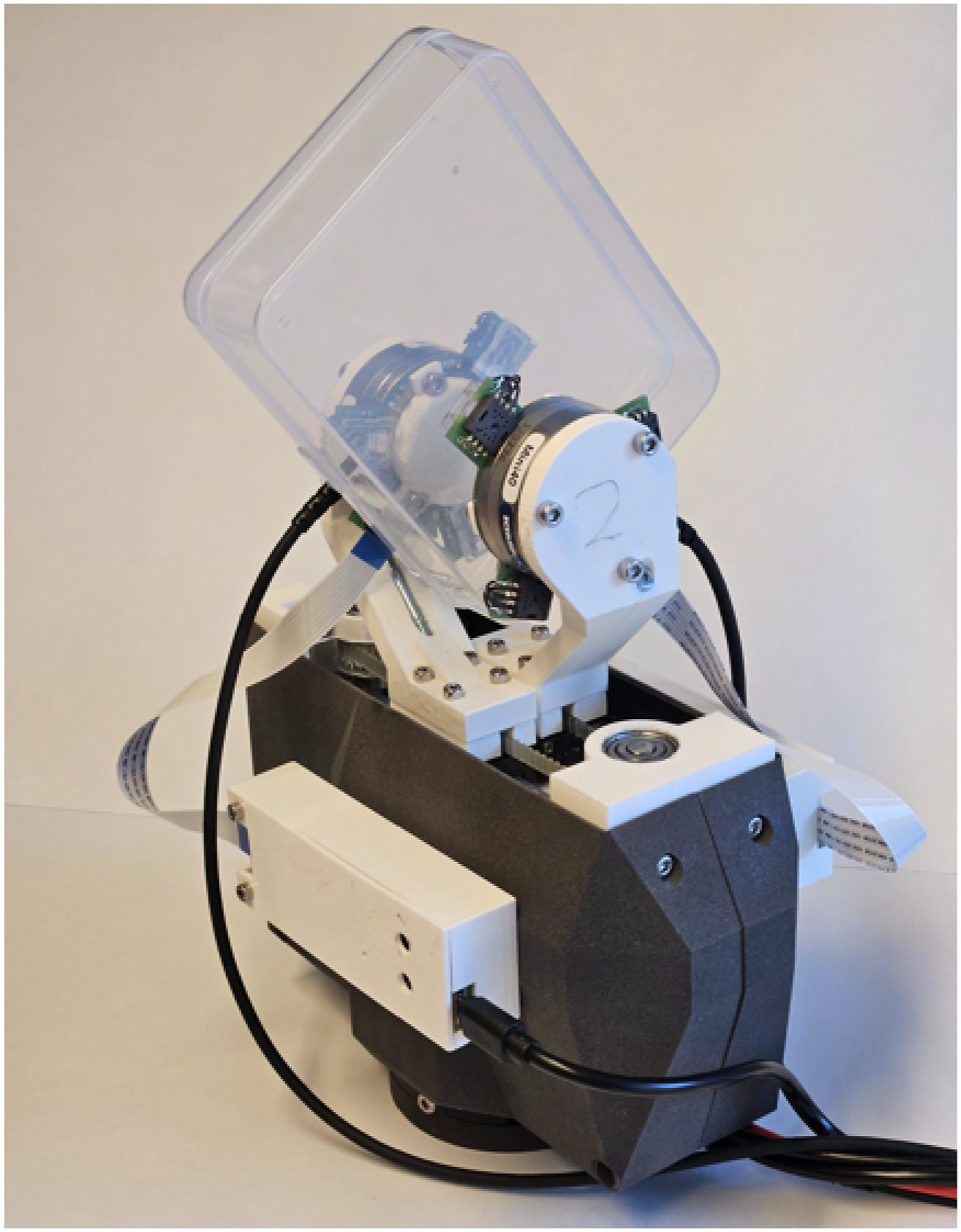
Slip-aware control significantly enhances the functionality of robotic manipulators by enabling the object-end-effector relative pose to adapt during grasping, thereby extending the operational workspace. This adaptability is particularly valuable in constrained environments, where the manipulator’s movement is limited, or for intelligent human–robot interaction, enabling for instance more intuitive and safe handovers. Furthermore, in-hand slippage control opens up new opportunities for multi-arm manipulation of single objects, allowing for the repositioning of grasps without releasing the object, thereby enabling more efficient and flexible handling of larger items. Our system has been rigorously tested across a wide range of experiments, demonstrating its effectiveness and versatility.
Related work
Tactile sensors
In-hand perception and manipulation are intrinsically tied to hardware. The gripper’s structure and the number of DoF dictate its dexterity. The design of tactile sensors is closely linked to the contact properties, which play a crucial role in influencing both sliding and grasping behavior. Numerous tactile sensors have been developed, and comprehensive reviews can be found in Chen et al. (2018), Kappassov et al. (2015), Dahiya et al. (2010), Yousef et al. (2011), Chi et al. (2018), and Lyu et al. (2025). A notable example is the GelSight sensor (Yuan et al., 2017), which evolved from the GelForce sensor (Kamiyama et al., 2005). The GelForce sensor utilized two layers of markers within an elastomer to detect a 3D force field over a 2D surface. Building on this, the GelSight sensor (Yuan et al., 2017), an advancement of the predecessor described in Johnson and Adelson (2009), features a clear elastic polymer with a reflective coating. A camera and multi-angled LEDs behind a rigid transparent plate capture deformations, using colored shading to reconstruct the 3D imprint. Surface markers enable estimation of shear forces and the reconstruction of a 6-axis force vector. The GelSight sensor has been commercialized and widely adopted in research. Another commercially available sensor is the BioTac sensor (Wettels et al., 2014), which has a finger-like appearance and is capable of measuring 3-axis force, vibrations, and temperature. Another approach is detailed in Costanzo et al. (2019) and De Maria et al. (2012), introducing a tactile sensor later named SUNTouch (Costanzo et al., 2023). This sensor is based on a deformable layer with cavities containing reflectors, where LED-phototransistors estimate deformation, allowing estimation of both the 6-axis F/T and surface deformation.
Several array-like tactile sensors have been proposed to measure the deflection of nibs, as demonstrated in Khamis et al. (2018), Yao et al. (2022), Wang et al. (2019), and Huh et al. (2020). Huh et al. (2020) introduced a tactile sensor specifically designed for simple in-hand manipulations, which dynamically clusters nib measurements, allowing for either faster data acquisition or higher spatial resolution. This concept of faster measurements was further expanded in Gloumakov et al. (2024), where nib vibrations were captured to estimate sliding velocity. Alternatively, Damian et al. (2015) explored the use of ridges on a flexible sensing resistor (FSR) sensor to estimate both velocity and position of sliding objects. Earlier approaches include the work of Howe and Cutkosky (1989), who developed a tactile sensor with a rubber skin embedded with an accelerometer to detect vibrations during slippage. The TacTip sensor, originally developed by Chorley et al. (2009), has been adapted into various versions that can be easily manufactured using rapid prototyping techniques, as described in Ward-Cherrier et al. (2018). Recent studies have explored fiber-optic methods for in-hand motion tracking (Tripicchio et al., 2023; Qian et al., 2018; Lu et al., 2022), showing promise for pressure, position, and force sensing free from magnetic interference.
Our approach differs from previous work by focusing on measuring in-hand force and planar velocity using independent sensing modalities. We achieve this by equipping the gripper fingers with both F/T sensors and custom relative velocity sensors based on optical mouse sensors. Optical mouse sensors have previously been explored for in-hand object manipulation to a limited extent, prior studies include Maldonado et al. (2012), which integrated single optical mouse sensors into the fingertips of the DLR/HIT hand (Liu et al. (2008)) for slip avoidance and object recognition. Sani and Meek (2011) used a single optical mouse sensor for slip detection, and Höver and Harders (2010), which employed an optical mouse sensor to capture tool displacement.
Grippers
Parallel grippers typically possess only a single DoF of control, which limits their capability for dexterous in-hand manipulation. As a result, these grippers often rely on external factors such as gravity, external contacts, or the inherent dynamics of the object to achieve complex tasks. Given the single DoF control and the rapid onset of slip events, precise and fast control becomes essential for effective manipulation. However, commercially available grippers often lack accessible, fast low-level force control, which is critical for such tasks.
Given access to sufficient bandwidth, velocity, or position-controlled grippers can be used to indirectly control grasping force with additional sensors (Viña B. et al., 2016); however, few commercial grippers offers this functionality. One discontinued commercial option is the WSG50 gripper, as utilized in Costanzo et al. (2023), which, with custom software modifications, achieves an external control rate of 50 Hz. In contrast, custom grippers using Dynamixel servo motors have been employed in various studies (Bi et al., 2021; Gloumakov et al., 2024; Zhang et al., 2022), with a reported response time of 0.12 s (Gloumakov et al., 2024). A different example is a custom gripper integrated with force and vibration sensors, as described in Zaki et al. (2010). Additionally, Wang et al. (2016) introduced a dual-motor parallel gripper, which combines a position controller with a closed-loop force controller. Another approach, described in Piga and Natale (2023), involves an adaptive force controller for low-resolution, position-controlled parallel grippers, demonstrating sliding manipulation with external object tracking.
A two-phase finger for a parallel gripper was proposed by Chavan-Dafle et al. (2015), allowing easier reorientation by switching between free-spinning contact and firm grasp. At lower grasp forces, the finger acts as a point contact, while at higher forces, it provides a stable contact surface. Dafle et al. (2014) employed a three-finger, single-motor gripper to perform in-hand reorientation of objects using external forces.
Anthropomorphic hands represent another approach to in-hand manipulation. Vision-based object reorientation has been demonstrated using the Shadow Dexterous Hand with reinforcement learning (OpenAI et al., 2019), and an overview of related learning-based methods is provided in Weinberg et al. (2024). The RBO Hand 3, a soft hand with 16 degrees of actuation, achieves in-hand manipulation using simple controllers (Puhlmann et al., 2022; Bhatt et al., 2021). However, the mechanical complexity of anthropomorphic hands presents challenges for reliability, durability, and cost-effectiveness (Huang et al., 2025). Recent efforts to address these limitations include low-cost designs enabled by rapid prototyping (Yang et al., 2021) and actuator-reduction strategies to simplify control and reduce cost (Kontoudis et al., 2019; Odhner et al., 2014; Santina et al., 2018).
Slip control and estimation
Estimation of friction and contact properties plays a crucial role in enabling effective in-hand slip-aware control. For instance, in Costanzo et al. (2023), the authors advanced their research on planar in-hand sliding control using the SUNTouch sensor. Their approach involves estimating angular velocity based on the limit surface concept and the LuGre friction model (Åström and Canudas-de Wit, 2008), utilizing estimated friction parameters in conjunction with F/T measurements. By estimating the center of rotation (CoR), they infer the linear velocity from angular velocity estimates. The estimated CoR is constrained to be within 1.5 times the contact radius, which limits the planar velocity estimation to be primarily rotational. The friction estimation method employed in Costanzo et al. (2023) is detailed in De Maria et al. (2015). Our approach does not impose such constraints on planar velocity estimation and allows for pure linear slippage as well as rotational.
Understanding the contact properties between the gripper and the object is essential for achieving controlled slippage. In previous work, we proposed a LuGre-based planar friction model for simulating in-hand slippage (Arslan Waltersson and Karayiannidis, 2024). Xydas and Kao (1999) modeled the contact mechanics for soft finger contacts based on the limit surface concept (Goyal et al., 1989, 1991) and linear elastic contact models, originally described by Hertz (1896). Additionally, in Le et al. (2021) combined visual and haptic data to estimate friction and assign friction coefficients to material segmentation based on camera input.
In Viña B. et al. (2015) and Viña B. et al. (2016), a trajectory-following controller was introduced for controlled rotational slippage in a parallel gripper, using an external camera for object pose tracking. The optoforce tactile sensor (Tar and Cserey, 2011) was employed in Viña B. et al. (2016) alongside an adaptive controller to compensate for errors in the friction coefficient. A framework for picking up and pivoting objects from a flat surface was presented in Holladay et al. (2015). Huh et al. (2020) used a custom sensor to stand objects upright on a flat surface, and the same sensor was employed in Gloumakov et al. (2024) to estimate slipping velocities and accelerations, enabling fast in-hand linear slippage. Chen et al. (2021) employed neural networks with the BioTac sensor to estimate linear sliding velocity and implemented a closed-loop controller to maintain a consistent sliding velocity.
In other in-hand slippage research, Bi et al. (2021) utilized custom tactile sensors for swing-up control. The GelSight sensor was employed by Wang et al. (2021) to identify physical features through exploratory movements aimed at dynamically swinging up objects. Chavan-Dafle et al. (2020) used motion cones with a gripper and an external pusher to plan the reorientation and repositioning of objects to achieve a desired final pose. Hou et al. (2018) demonstrated the ability to reorient objects using two motion primitives, pivoting and rolling on a table, with a gripper featuring two-phase fingers that enable both a firm grasp and pivoting.
Contributions and overview
This paper presents an architecture for in-hand slip-aware control, featuring a high-performance sensorized gripper. The architecture facilitates in-hand slippage in both linear and rotational directions using simple controllers. These slipaware controllers enables us to extend the capabilities of parallel grippers and relax the assumption of a rigid grasp. Initial estimation of Stribeck friction parameters Stribeck (1902) and the contact radius allows for manipulation of unfamiliar non-fragile planar objects. The key contributions are: (1) (2) (3) (4)
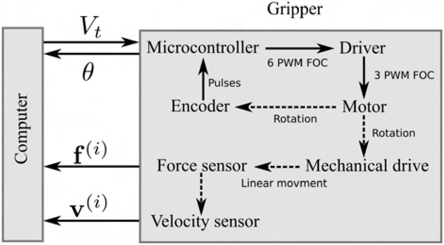
An overview of the system is shown in Figure 2. The gripper, equipped with F/T and velocity sensors, is mounted on a robot arm. A grasp force controller—based on the F/T sensors Overview of the architecture with the inner and outer control loops, the mechanical connections are marked with dashed lines and information pathways are marked as solid lines.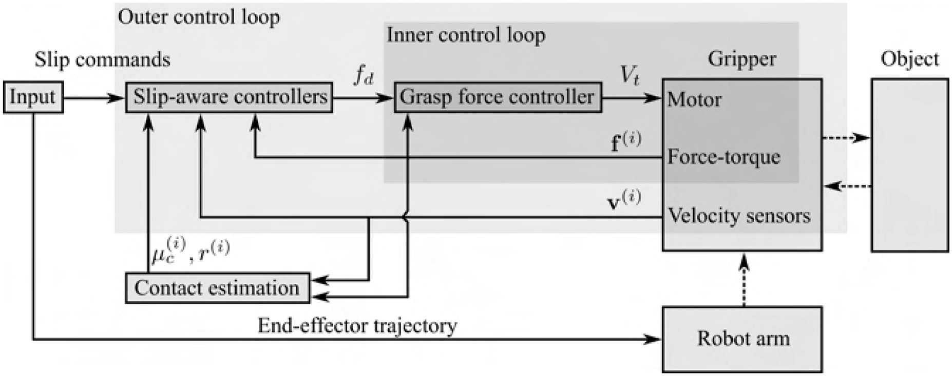
The paper is structured as follows: Section Gripper design presents the design of the gripper and the grasp force controller. The Velocity sensor design section details the relative velocity sensors and their calibration. The method for estimating contact properties is described in Section Estimation of contact properties. The Controlled slippage section introduces the four slip-aware controllers. Experimental results are presented and analyzed in the Results section. Finally, the Conclusions section summarizes the paper.
Gripper design
Commercial grippers are generally not designed for in-hand sliding manipulation tasks and often lack accessible low-level force control. To address this limitation, we present a high-performance, force-controlled gripper. This permits treating the force response as near-perfect in the design of the slip-aware controllers. This section details the hardware design of the gripper and the grasp force controller. The gripper features a high-performance motor and efficient field-oriented control (FOC), with the low-level FOC controller running on an ESP32-S3 microcontroller. The design incorporates commercially available components and rapid prototyping techniques, such as 3D printing.
Hardware
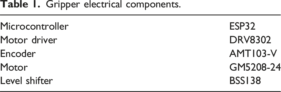
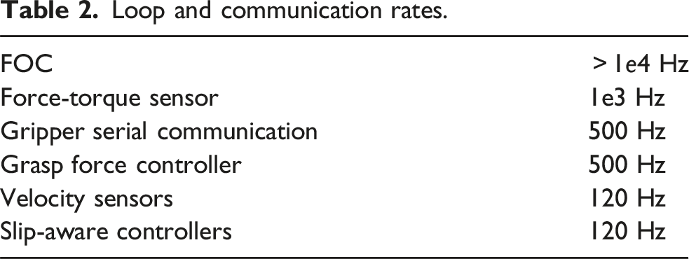
The gripper is designed to be quasi-direct drive for rapid force control and its overall dimensions be seen in Figure 3, while the construction and internal components are detailed in Figure 4. The electrical components are listed in Table 1. The gripper is powered by a high-torque, low Kv BLDC motor, originally designed for camera gimbals and optimized for operation under stalled conditions, for example, when grasping objects. This motor is controlled using FOC based on the SimpleFOC library (Skuric et al., 2022). An encoder, directly attached to the motor output, provides real-time feedback to the FOC algorithm, ensuring constant torque regardless of the rotor orientation. The encoder also allows for the calculation of finger position and velocity. The motor is driven by a DRV8302 motor driver, with a software-limited maximum output of 1 A at 20V. The encoder connected to the ESP32 microcontroller via a voltage level shifter, offering an effective resolution of 4096 counts per revolution using the ESP32’s hardware pulse counters. The communication between the gripper and a computer is handled over USB serial at 500 Hz, with motor angle data θ transmitted and target voltage commands V
t
received. Figure 5 illustrates the communication pathways, while Table. 2 summarizes the system’s operational rates. Gripper viewed from the side with the overall dimensions. The internal components of the gripper. Gripper electrical components. The communication inside the gripper and with the computer. Loop and communication rates.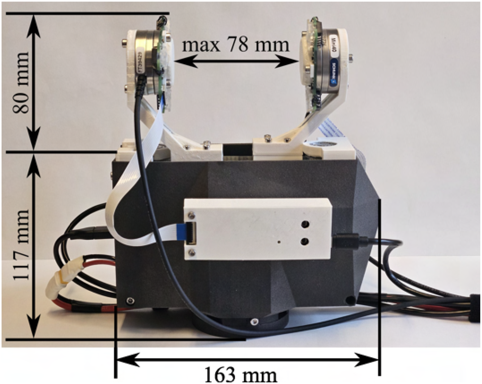
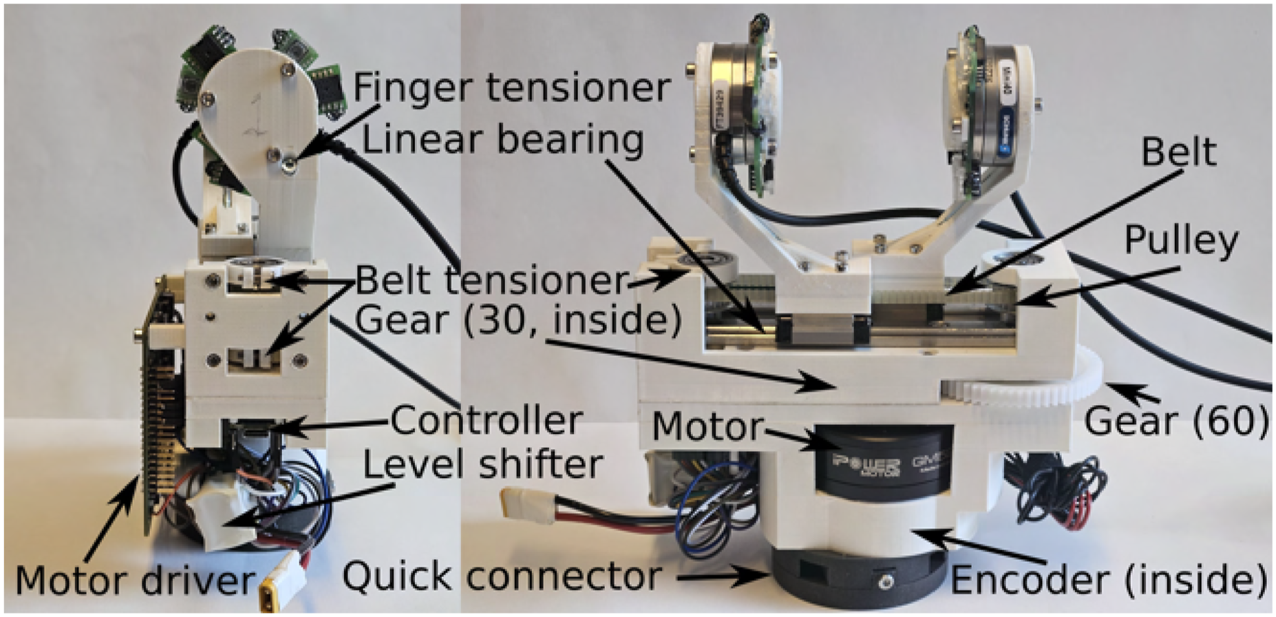
The gripper’s body is primarily constructed using rapid prototyping techniques. As shown in Figure 4, all white components, except the gears, are 3D-printed in PLA using an FDM printer, while the outer shell and quick connector are produced via SLS printing. The motor is coupled to a 2:1 gear ratio, effectively doubling its torque output while maintaining a quasi-direct-drive configuration. This output gear drives a belt pulley system that converts rotational motion into linear motion. Each belt pulley has 22 teeth and a diameter of 17.51 mm, resulting in 27.5 mm of linear travel per motor revolution for each finger. The gripper achieves a measured maximum grasp force of approximately 45 N. The pulley and gear shafts are mounted on rotational bearings, while the fingers move along two linear bearings and are connected to the belt on either side. The finger design allows for a maximum grasp opening of 78 mm. Belt tensioning is achieved through adjustable screws, as depicted in Figures 4 and 6. The total weight of the gripper, including the sensors, is 1.23 kg. Sensors, finger and belt tensioning mechanism.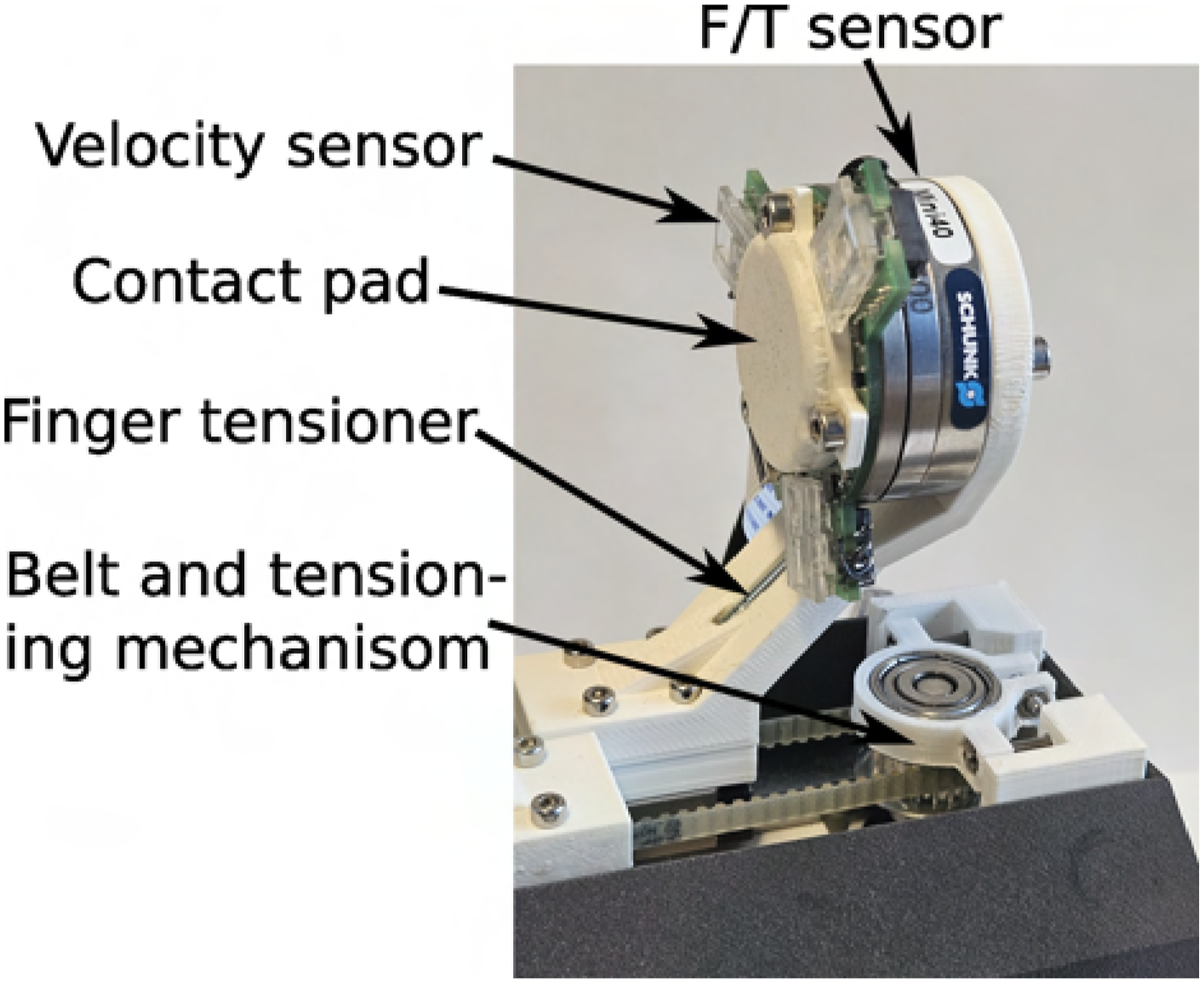
The contact pad (see Figure 6) is flat and rigid to accommodate the velocity sensors’ sensitivity to surface proximity. Designed for easy interchangeability, the contact pad is circular with a 15 mm radius and is 3D-printed from both PLA and TPU95. The TPU95 surface increases friction compared to PLA alone. The fingers, printed in solid PLA, tend to flex under load. To counteract this, a long M3 screw runs along the inner side of each finger, preloading one side to create an adjustable counter-flex, as partially visible in Figure 6.
Grasp force control
The grasp controller is responsible for rapidly achieving a desired grasp force f
d
, with the feedback f
n
from the F/T sensors. We model the gripper and analyze it to motivate our grasp force controller. The controller outputs a commanded force, f
c
, which is translated into a target voltage V
t
for the FOC algorithm as follows: Simplified model of gripper dynamics.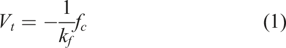


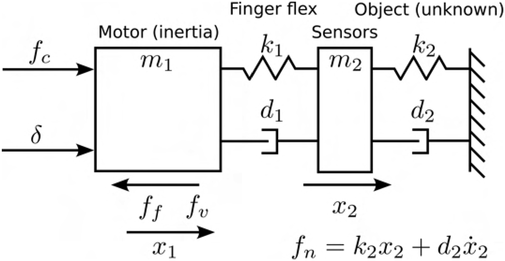
To analyze stability of the system with states 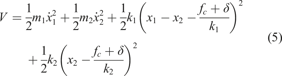

The friction f
f
and back emf f
v
always act in the opposite direction of 
As V is positive definite and 
Adding 
Velocity sensor design
In this section, we present the design of a planar velocity sensor, which is mounted between the F/T sensor and the contact pad, see Figure 6. This allows the overall sensor set-up to accurately measure both the planar sliding velocity and the forces using in-hand sensing. An overview of the sensor and its associated microcontroller is provided in Figure 8. Overview of velocity sensor.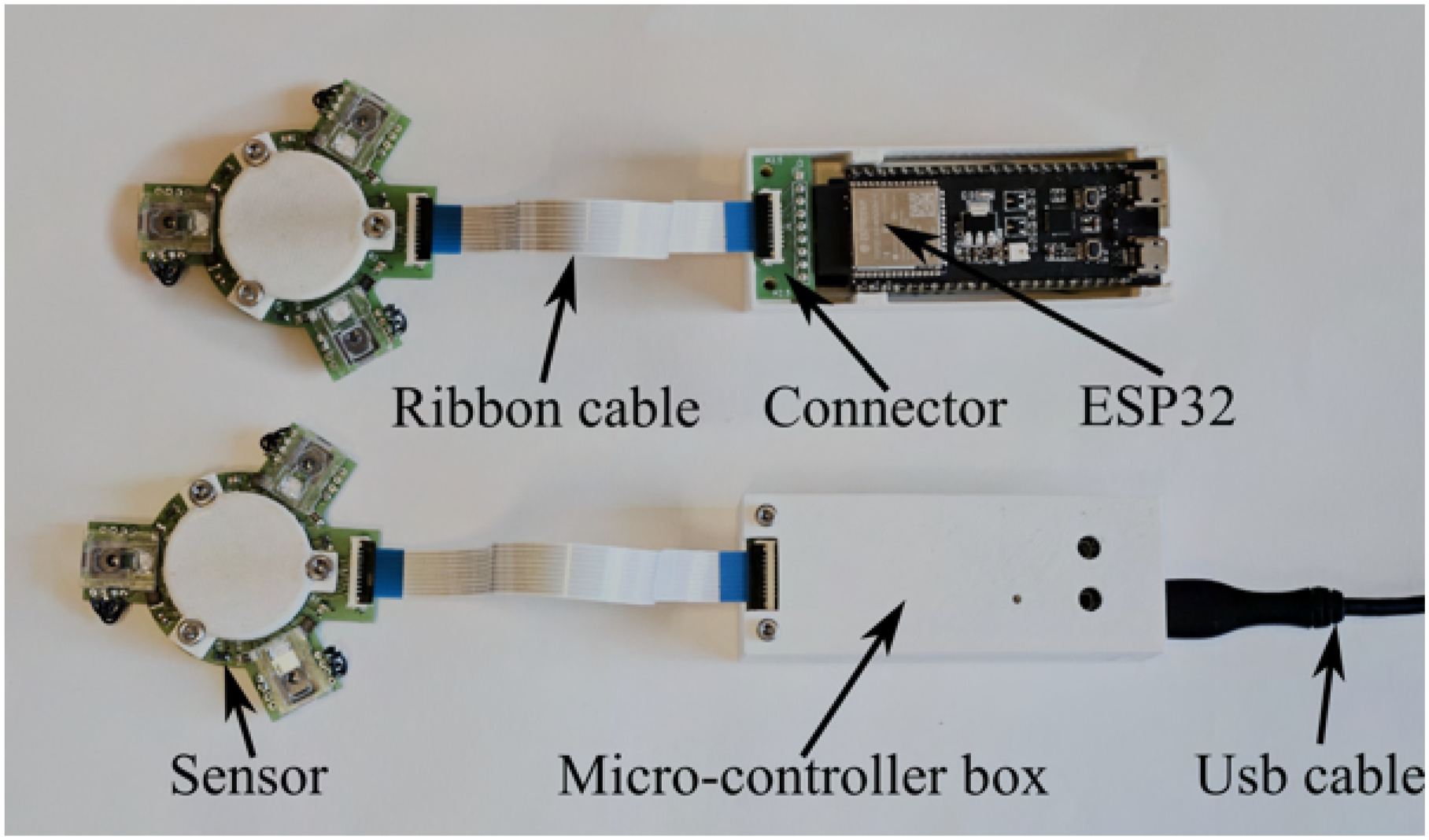
Planar velocity sensor
The proposed sensor consists of three optical mouse sensors arranged 120° apart in a circular pattern, allowing it to measure linear and rotational relative velocities with redundancy. The sensor is connected via a flexible ribbon cable to an ESP32-S3 microcontroller, as shown in Figure 8. The microcontroller communicates with a computer over USB serial, see Table 2 communication rates. The sensor assembly is built on a custom PCB, depicted in Figure 9. The optical mouse sensors (PAW3205DB-TJNT), along with the lenses and LEDs, are repurposed from a Rapoo M300 mouse. The optical sensors are mounted on the back of the PCB, while the LEDs are mounted under the lenses. The lenses are press-fitted into place, and the microcontroller enclosures are mounted on the sides of the gripper, as shown in Figure 1. PCB assembly of velocity sensor.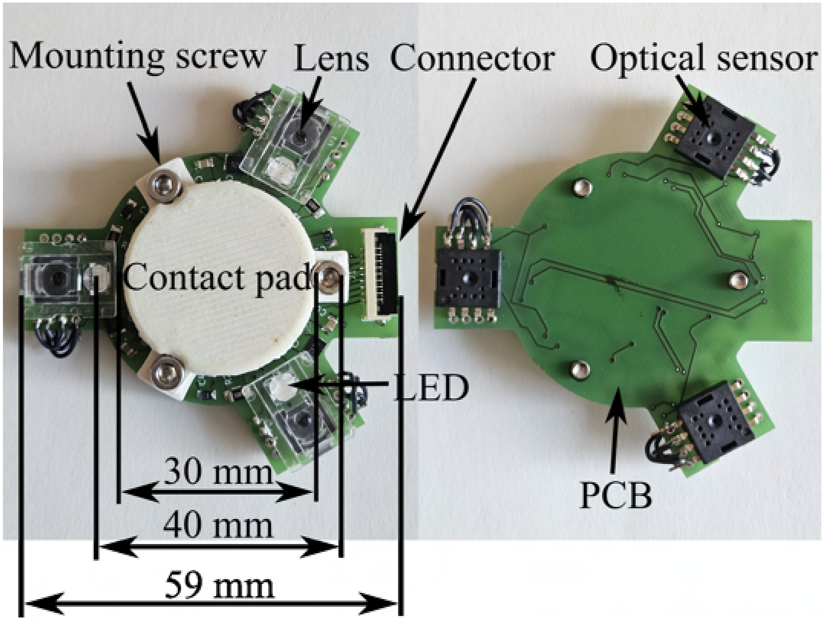
Experimental results show that each optical sensor operates at 3200 counts per inch (CPI), providing a spatial resolution of approximately 0.008 mm. Each sensor outputs the measured displacement in the x and y directions, with the sensor frames illustrated in Figure 10. The ESP32 microcontroller is configured with one core dedicated to half-duplex communication with the optical sensors, while the other core handles filtering and USB serial communication. The filtering and communication loop runs at 120 Hz, balancing low latency with accuracy. Frames of the optical mouse sensors and the combined velocity sensor in regards to the F/T sensor. The velocities are expressed in m/s or rad/s.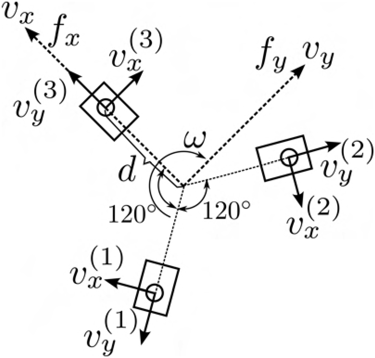
The filtering process is carried out in multiple stages: First, the average velocity within a time window is calculated for the x and y directions of each sensor. Next, each velocity is processed through a calibration filter. Finally, the velocity components are fused to output the sensor’s planar velocity. The filtering rate is crucial, as a rate that’s too high results in noisy velocity measurements, while a rate that’s too low introduces unnecessary delays. Minimizing delay is essential for accurately capturing slip and stick events. Common filtering techniques, such as tracking loops, Kalman filters, or other recursive or running average filters, often result in higher delay but lower noise. The velocity 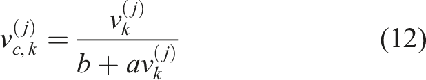
The velocity output of the planar velocity sensor is aligned with the F/T sensor, as illustrated in Figure 10. The output velocity 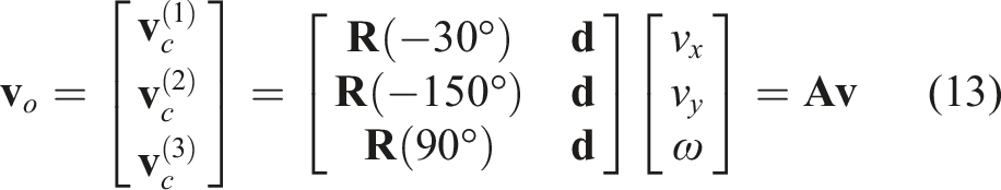

There is redundancy in the calculation of 
This approach allows for one of the three sensors to be outside the object, with minimal impact on tracking accuracy.
Velocity sensor calibration
The planar velocity sensors are calibrated and tested using the test rig shown in Figure 11. The rig features a cart that moves along linear tracks, with the sensor mounted on a rotatable shaft. Two adjustable stops are installed on the linear tracks, and the cart includes an angle selector, enabling controlled displacement during testing. Testing and calibration system for the velocity sensors. The test rig can be set up to test the sensor outlier system.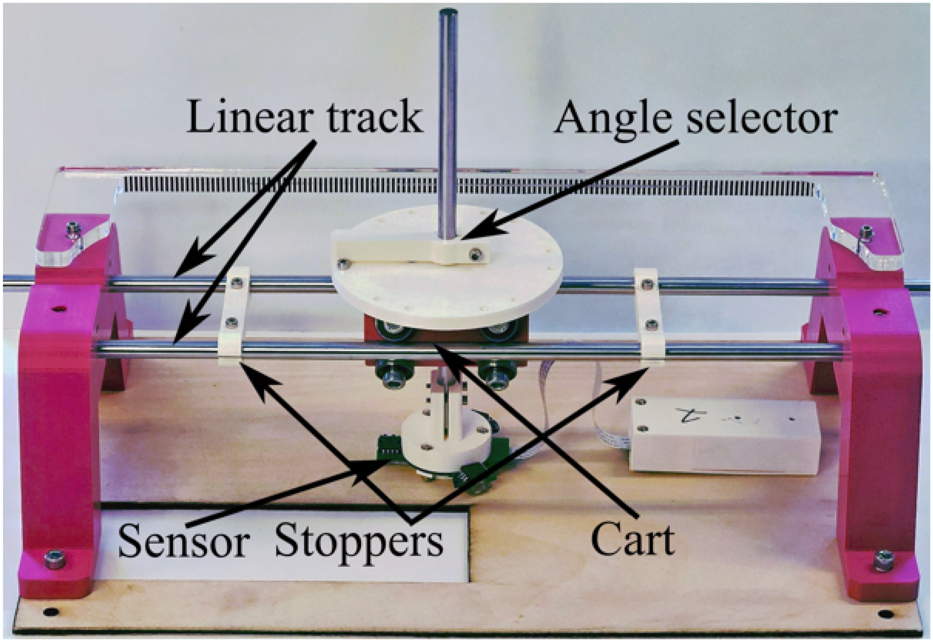
To calibrate the optical mouse sensors and determine the calibration parameters a and b from (12) for both x and y directions, the stoppers are set to allow 100 mm of linear travel for the cart. The angle selector is adjusted according to the specific sensor and direction being calibrated. Data is then collected by manually moving the cart between the stoppers at varying speeds. By knowing the displacement between the stops and calculating the average time taken, the true average velocity is obtained. The ratio between the measured and estimated velocities is then calculated and plotted across different speeds, as shown in Figure 12. Typical calibration example, we call the average true velocity vtrue and the raw measured velocity v
m
.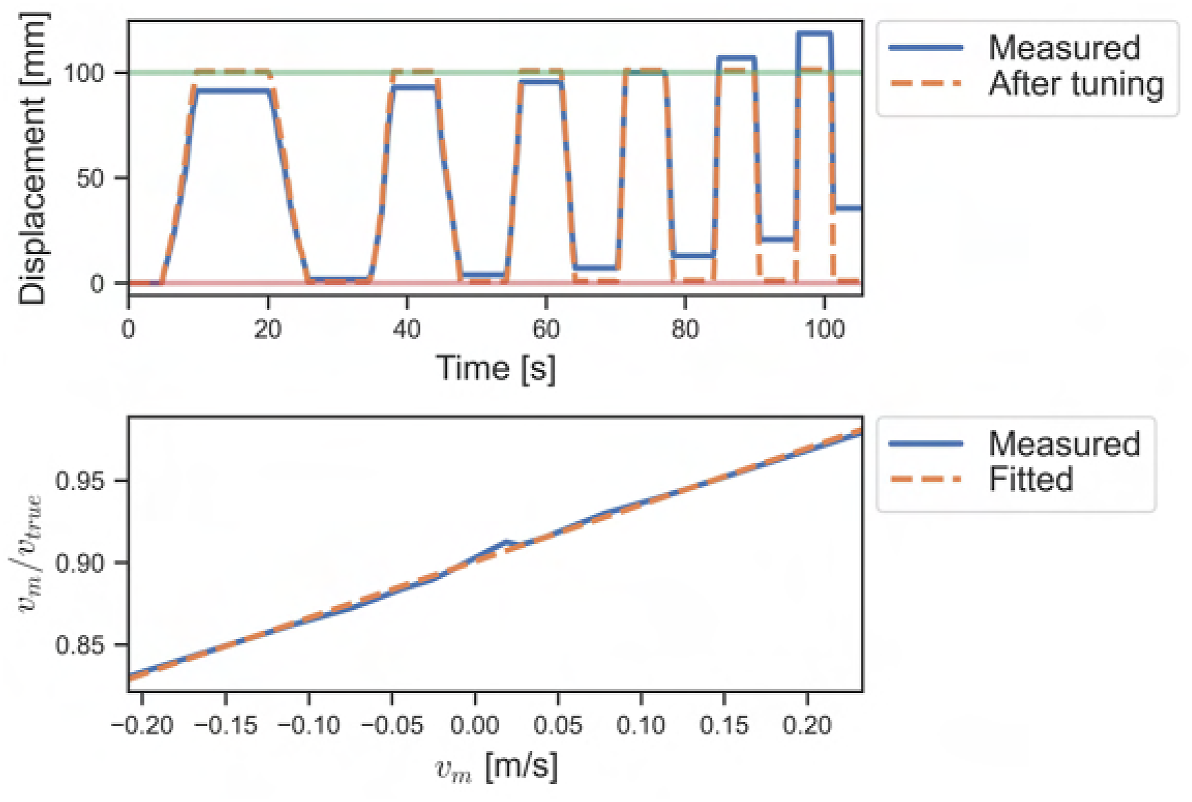
Linear regression is used to fit a line to the data, providing an initial estimate for a and b. These coefficients are then manually fine-tuned if necessary, as the automated parameter identification assumes a constant velocity, which is not always the case during manual actuation. The results before and after calibration are displayed in Figure 12. Additionally, the variable d is manually tuned by rotating the sensor 180° and adjusting d until the correct rotation is estimated.
Estimation of contact properties
This section outlines a two-step process for estimating key contact properties: the static, Coulomb, and viscous friction coefficients μ
s
, μ
c
, and μ
v
, as well as the radius r in a rim contact model, which approximates the limit surface as an ellipsoid (Arslan Waltersson and Karayiannidis, 2024). The estimations of μ
c
and r are later used in Section Controlled slippage for slip-aware control. First, a brief linear slippage exploration is performed during the pickup phase while the object rests on a surface, as illustrated in Figure 13. The process begins by grasping the object with a normal force f
g
. After time t1, a linear motion with displacement d
e
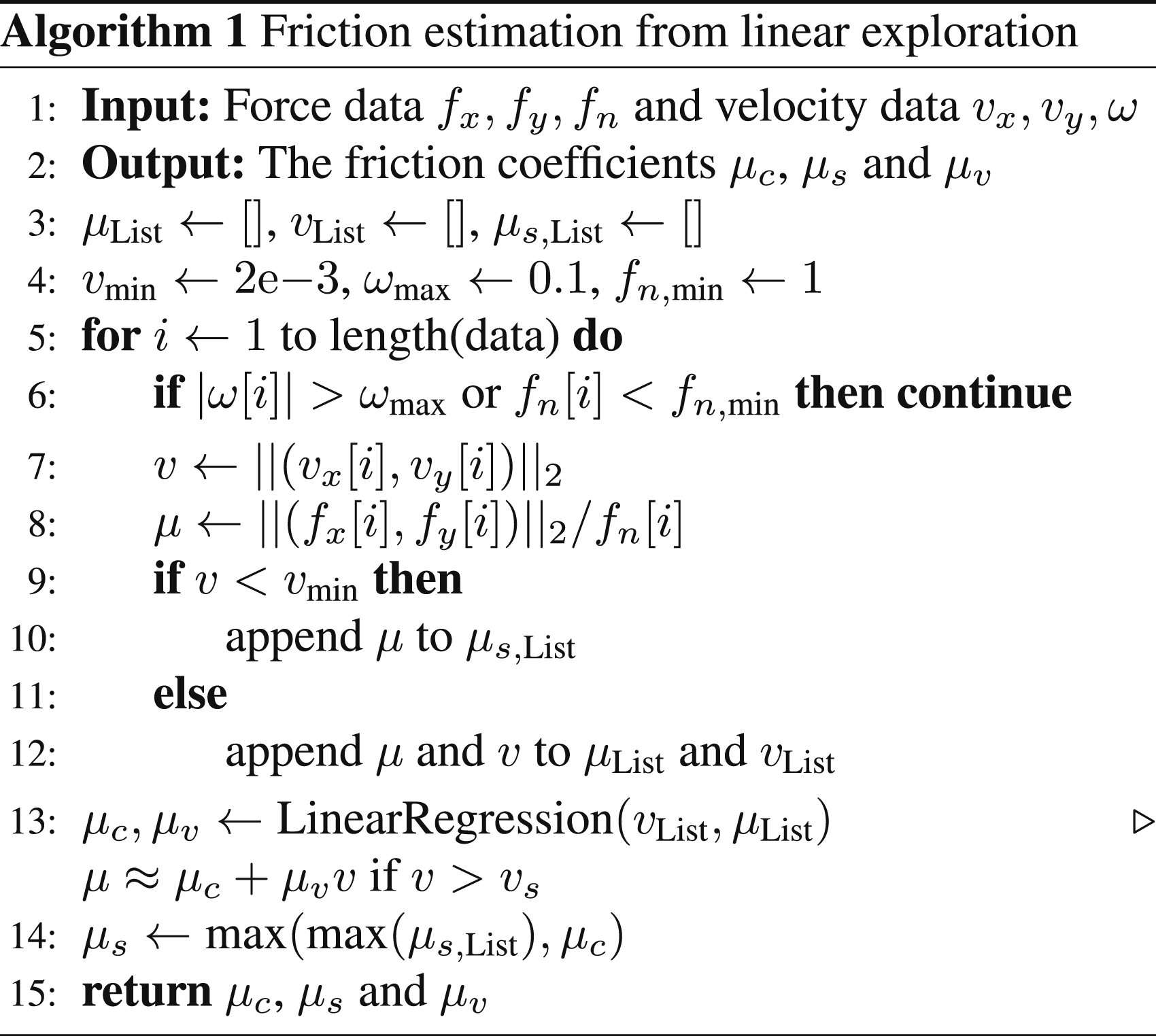
downwards towards the surface is initiated, lasting for a duration of t2. The data collected from this linear exploration is processed using Algorithm 1 to estimate the friction coefficients. Each finger is evaluated independently, which allows the method to accommodate objects with different materials on either side. Forces and velocities are measured at the contact point, eliminating the need for precise velocity tracking by the robot manipulator. The algorithm discards data points with excessive angular velocity, as these tend to skew the results toward lower friction coefficient estimates according to limit surface theory (Goyal et al., 1989). Linear and rotational exploration for estimation of contact properties.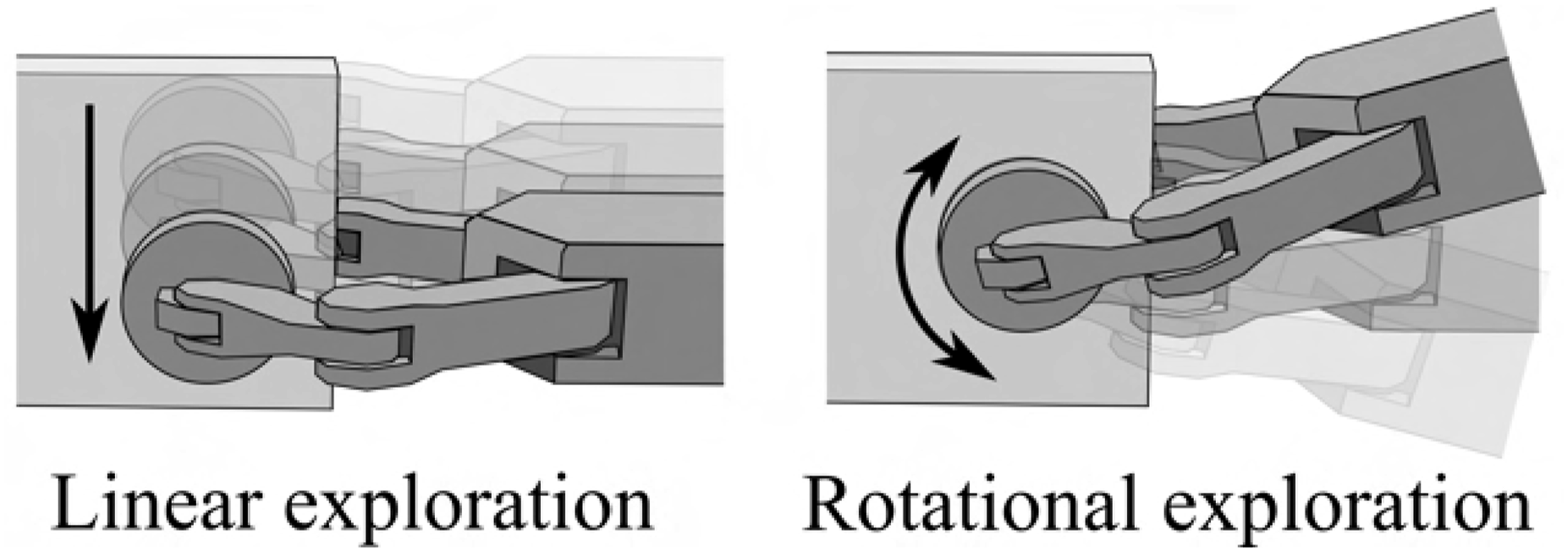
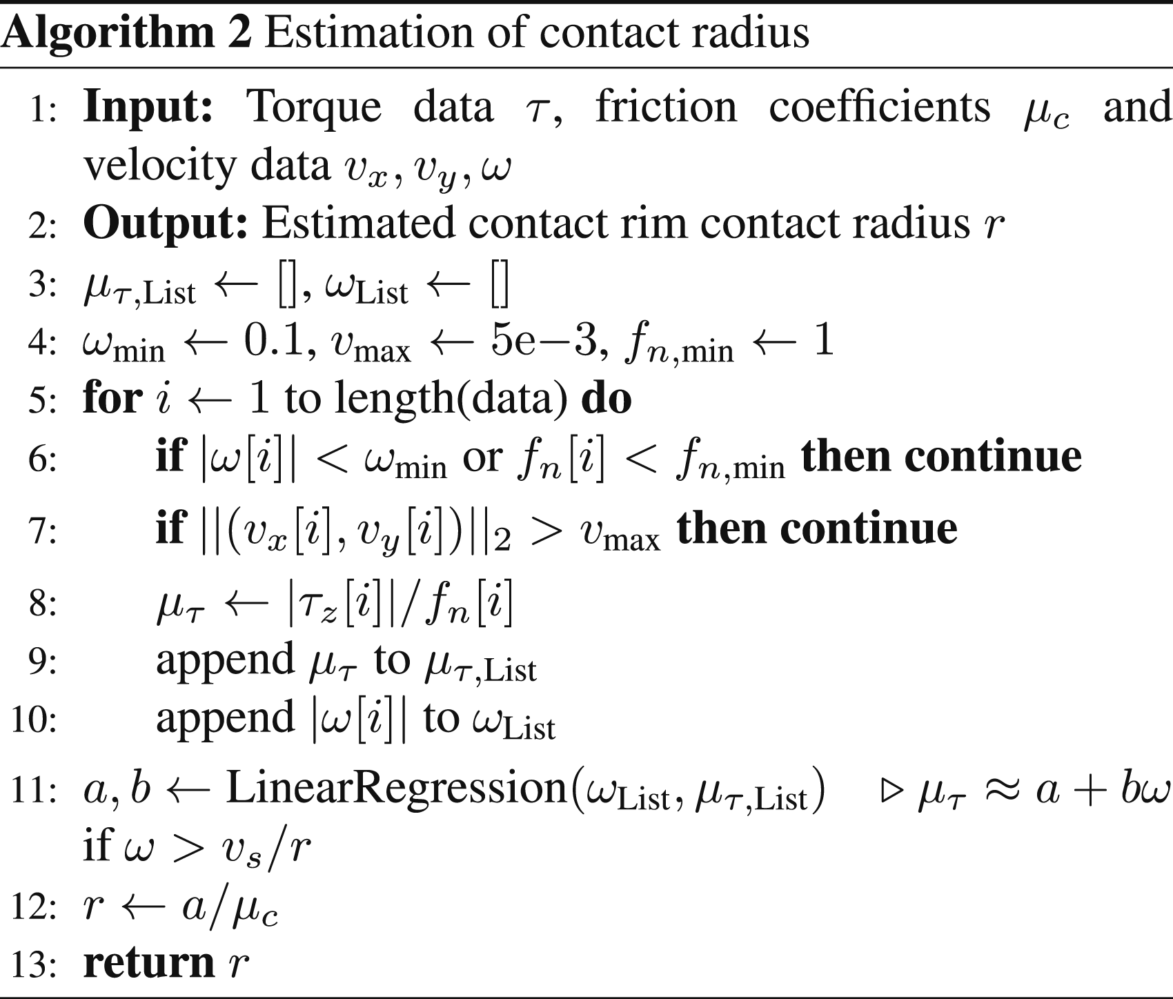
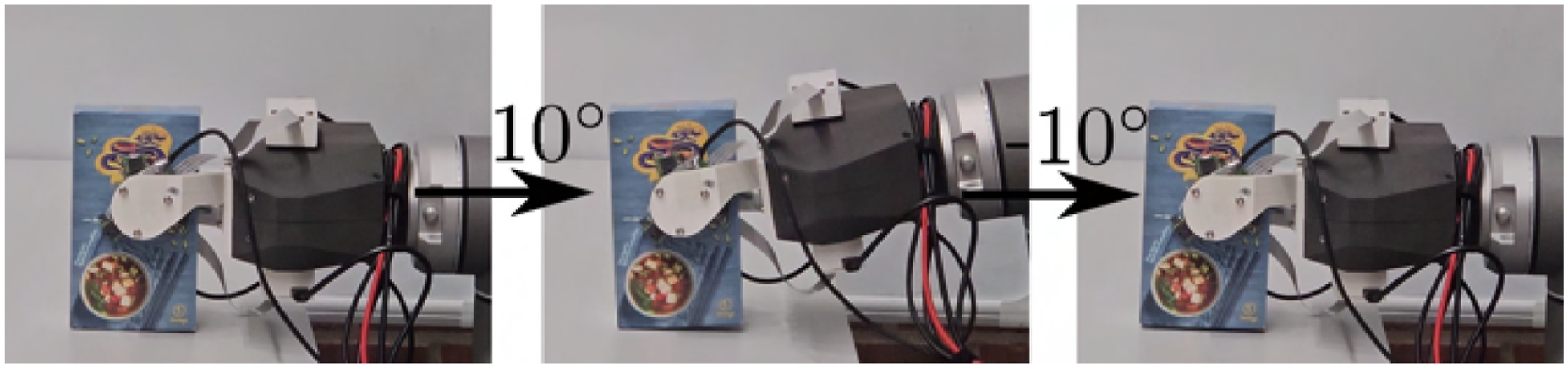
Following the estimation of the friction coefficients, a rotational exploration phase is conducted to estimate the contact radius of an equivalent rim contact. This phase is illustrated in Figure 13. During this phase, force and velocity data are collected while the gripper rotates θ e over a period of t θ and then returns to its original orientation. The algorithm used to estimate the contact radius r is detailed in Algorithm 2. The estimated radius r will subsequently be used to estimate the limit surface of the contact area. Overall, the friction coefficients and contact radius can be estimated within 2 s of grasping an object.
Controlled slippage
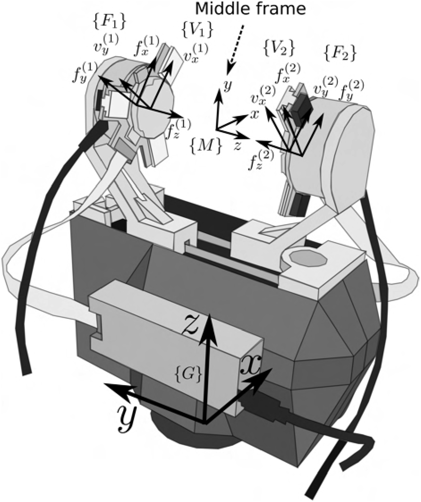
In this section, we present four slip-aware controllers: linear slippage, rotational slippage, hinge control, and slip-avoidance, as illustrated in Figure 14. These controllers are designed to be simple and to be used as control primitives for more complex tasks. They build on top of the grasp controller from Subsection Grasp Force Control and are experimentally verified. The notation Four different slip control modes. The frames of the gripper.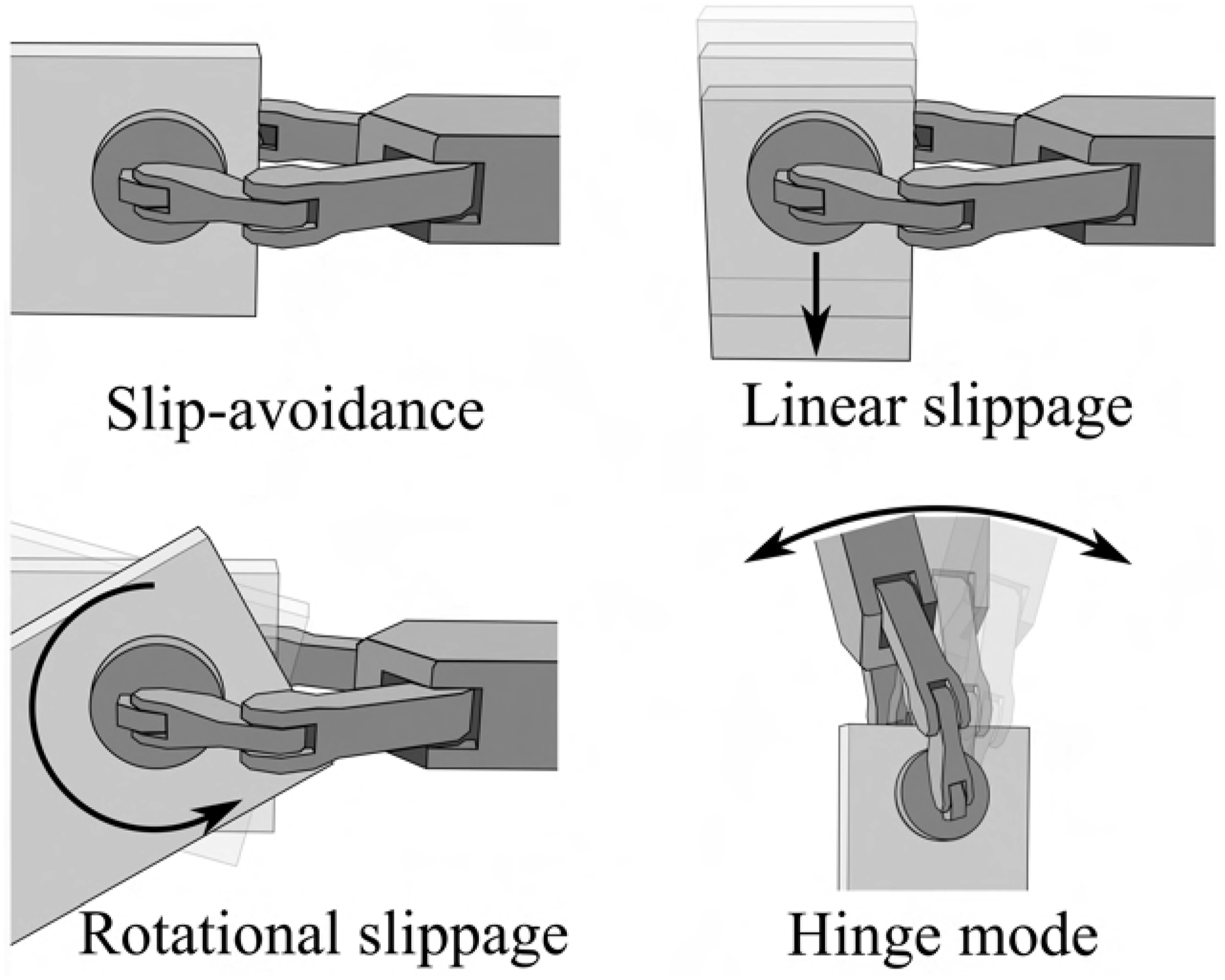
Slip-avoidance
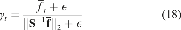
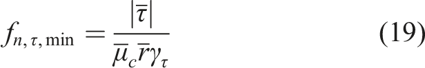
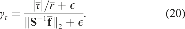
The primary focus of the slip-avoidance controller is to adjust the grasping force to securely hold an object without excessive grasp force. Let 
This is used to calculate the minimum grasp force to counter the measured tangential forces: Illustration of the normalized limit surface.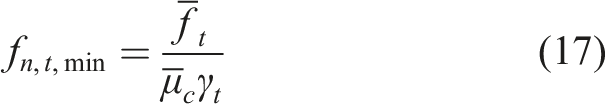
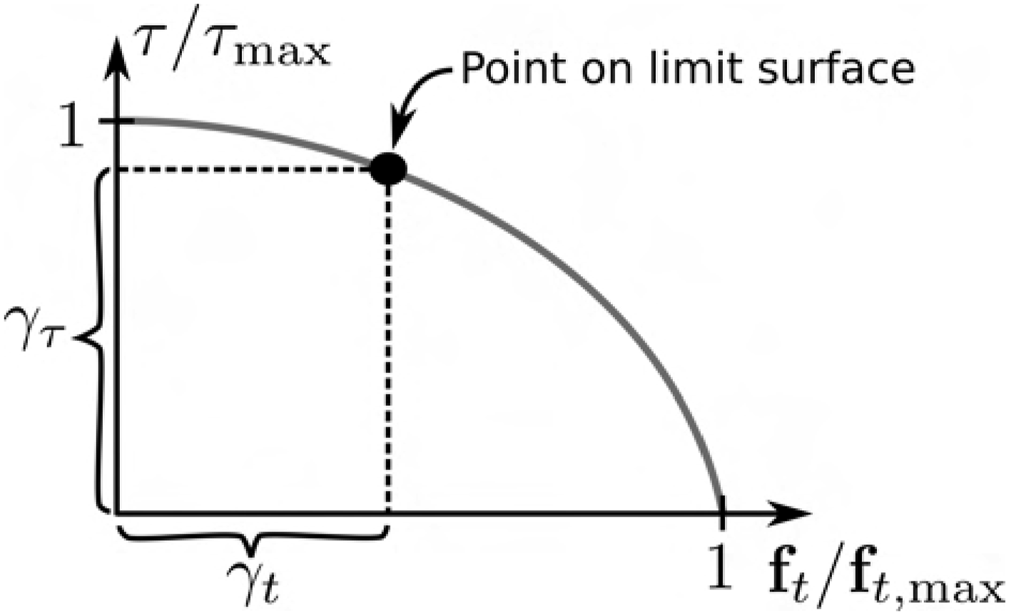
The overall grasp force, considering both torque and tangential forces, includes a tunable safety margin γ
s
and a velocity component to account for slippage:
Linear slip control
This controller allows the object to be repositioned within the gripper along the gravity vector. Let p
d
(t) and 
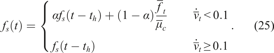
The grasp force controller designed to follow v
c
is a superposition of a PI“D” controller for tracking v
c
and a force control term based on f
s
(25) representing the normal force required to maintain the slip. The control law is given by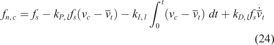
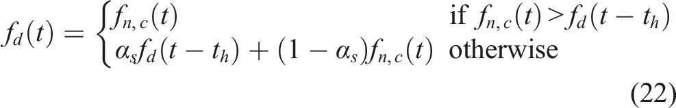
The computed grasp force f
d
for the inner loop controller is given by
Rotational slip control
In rotational slip control, the gripper remains stationary while the object rotates within the gripper under the influence of gravity; a similar problem formulation was explored in Viña B. et al. (2016). Let θ
d
(t) and 
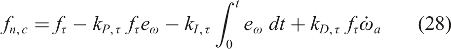
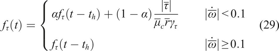
The grasp force sent to the inner loop controller is given by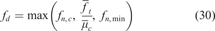
As with linear slip control, the controller switches to the slip-avoidance controller if either the target displacement has been reached or if the trajectory time has run out and the object is not moving towards the target.
Hinge mode
In hinge mode, the object is allowed to rotate freely within the gripper while preventing linear slippage by dynamically adjusting the grasp force. If the object’s center of gravity (CoG) is directly beneath the grasp point, the object remains stationary as the gripper rotates around it. The grasp force in hinge mode is calculated as follows: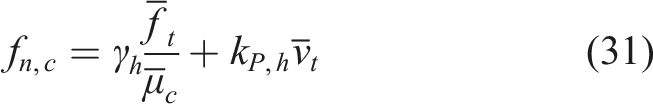

Results
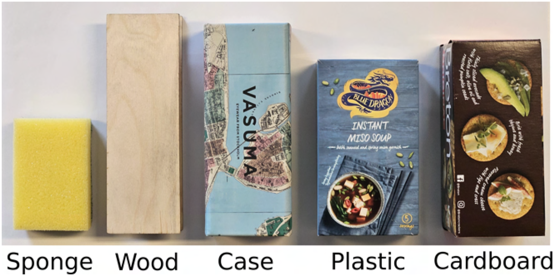
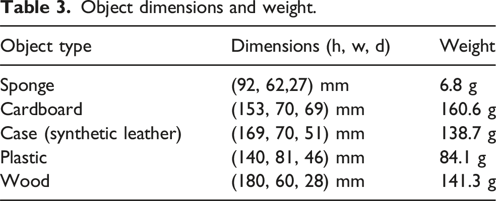
In this section, we present the experimental validation of the proposed hardware and methods. Various objects detailed in Figure 17 are used for the experiments. The dimensions and weights of these objects are listed in Table 3. Depending on the specific experiment, only a subset of these objects may be evaluated. The experiments are organized as follows: • • • • Test objects, the sponge is highly deformable, the wood object has a plywood surface and is rigid. The spectacle case has a synthetic leather material. The plastic object is a plastic covered cardboard box. The cardboard box has a paper finish. Object dimensions and weight.
The experiments were conducted using a laptop equipped with an Intel i7-1185G7 processor and 32 GB of RAM. The software and algorithms was implemented in ROS Noetic, and the UR10 robot was controlled using the Universal Robots ROS driver. The built-in task-based trajectory controllers were utilized for the robot’s movement.
Gripper performance
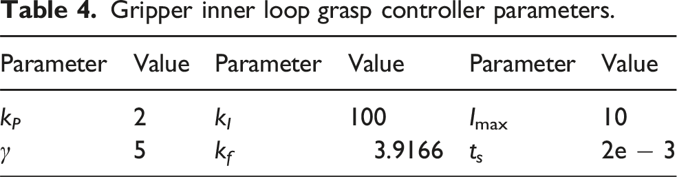
Gripper inner loop grasp controller parameters.
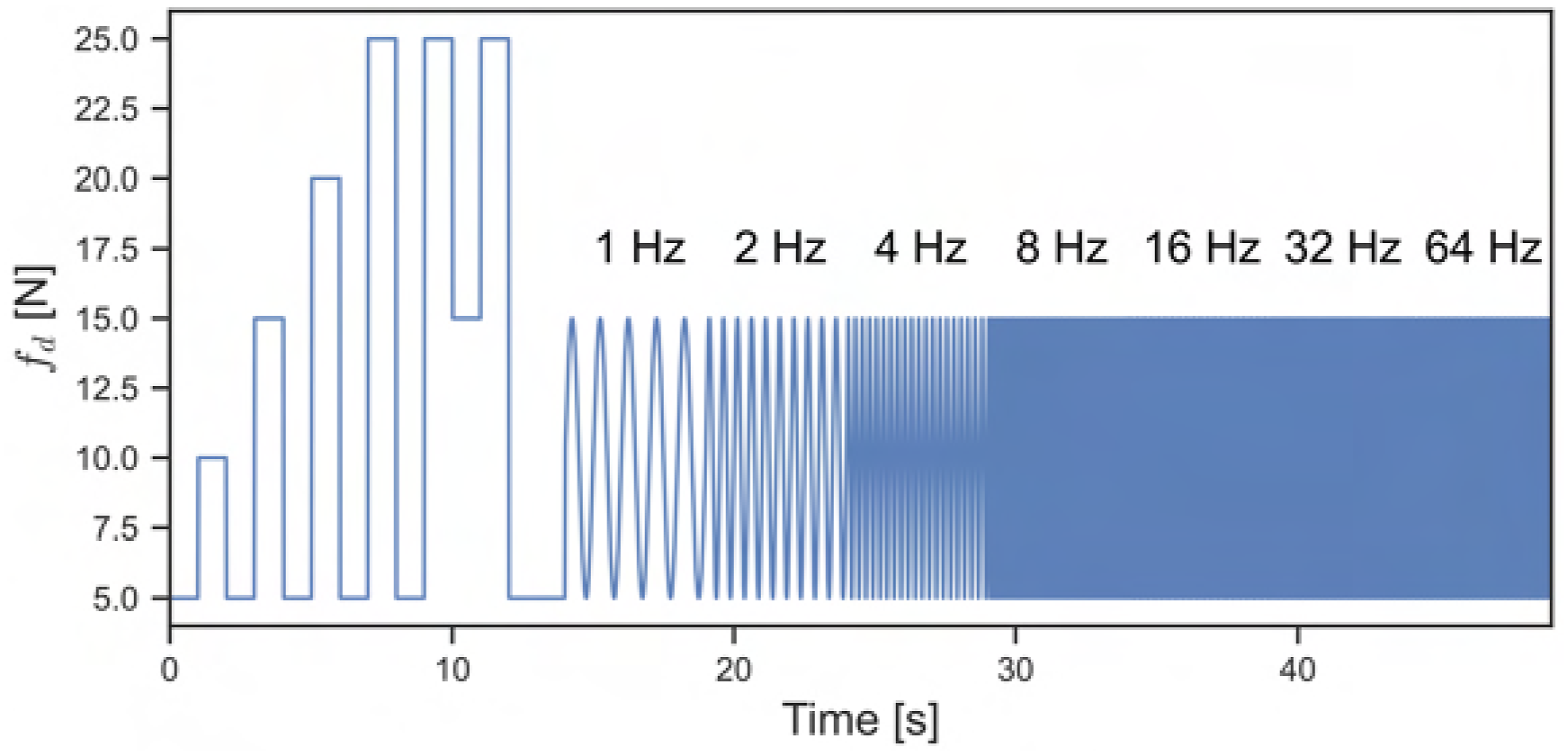
Force trajectory to test gripper performance.
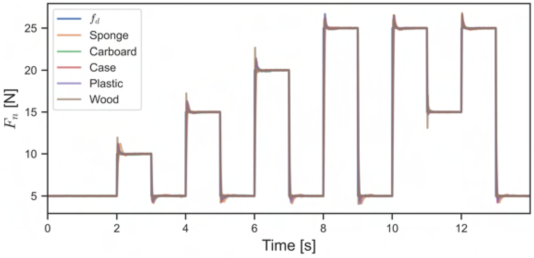
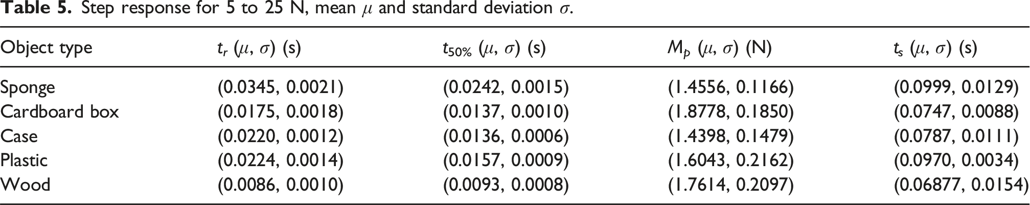
The gripper’s response time was measured during the transition between a force of 5 N and 25 N, with each object tested 10 times. A representative sample from each object is shown in Figure 19. The key metrics for evaluating the step response are: • • • • Step response of the gripper, one sample per object.
Step response for 5 to 25 N, mean μ and standard deviation σ.
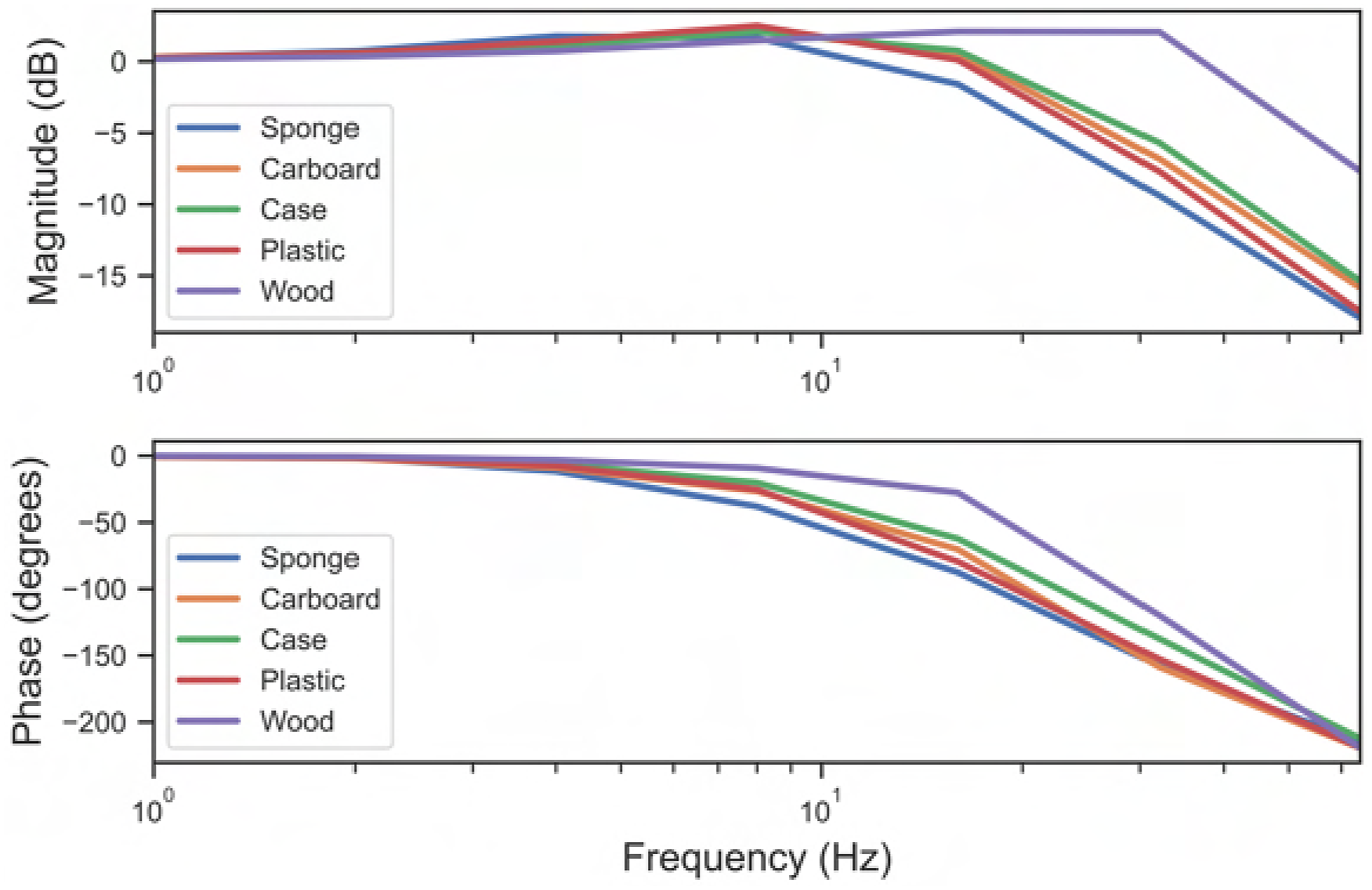
To evaluate the stability and performance of the gripper under time-varying target forces, the gripper was subjected to a sequence of sinusoidal signals with frequencies ranging from 1 to 64 Hz, as illustrated in Figure 20. The response was analyzed by computing the amplitude and phase for each frequency. The average results from 10 runs are presented in a Bode plot, see Figure 21. Figures 20 and 21 reveal that the magnitude increases at certain frequencies but remains bounded, indicating that stability is maintained throughout the testing range. As expected, the magnitude decreases at higher frequencies and the phase shifts accordingly. Notably, the phase exceeds 180° when the 64 Hz signal is applied. This phase shift can be attributed to the operational rates of the controller. Given that the inner loop controller operates at 500 Hz, a delay of 1/500 seconds for a 64 Hz signal would result in a phase shift of 46.08°, which would account for the shift beyond 180°. Overall, the combined analysis of the step response and Bode plot demonstrates that the inner loop controller is both stable and responsive. Tracking sinusoidal grasp force trajectory, one sample per object. Bode plot, shows an average of 10 runs for each object.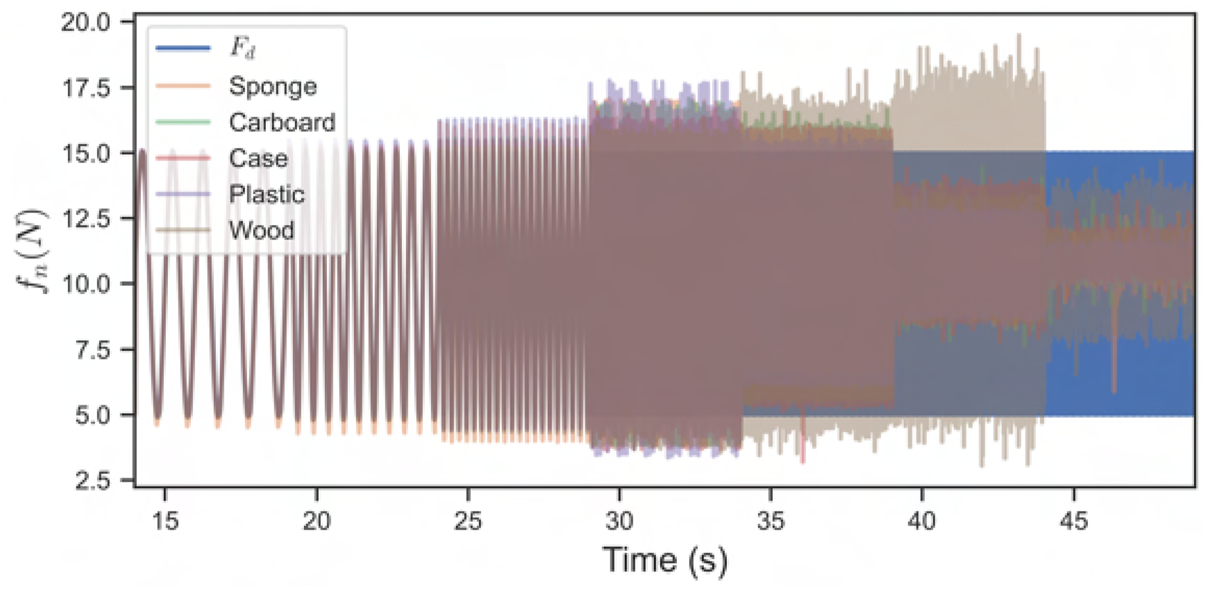
Relative velocity sensor
To estimate the accuracy of the velocity sensor in a controlled environment, four different tests were conducted using the test rig shown in Figure 11. These tests were designed to evaluate the sensor’s performance under various conditions: (1) (2) (3) (4)
During these experiments, the sensor’s estimated velocity was integrated to calculate the displacement, which was then compared to the known displacement from the test rig. Each experiment was repeated 10 times across the three surfaces shown in Figure 22. The results are presented in Tables 6 and 7. Three different surfaces: Wood, cardboard, and clear plastic film. The figure also shows the cut out for testing the sensor rejection system. Tracking error [mm] & [deg], mean μ, and standard deviation σ. Tracking error combined motion (100 mm and 180 deg), mean μ, and standard deviation σ.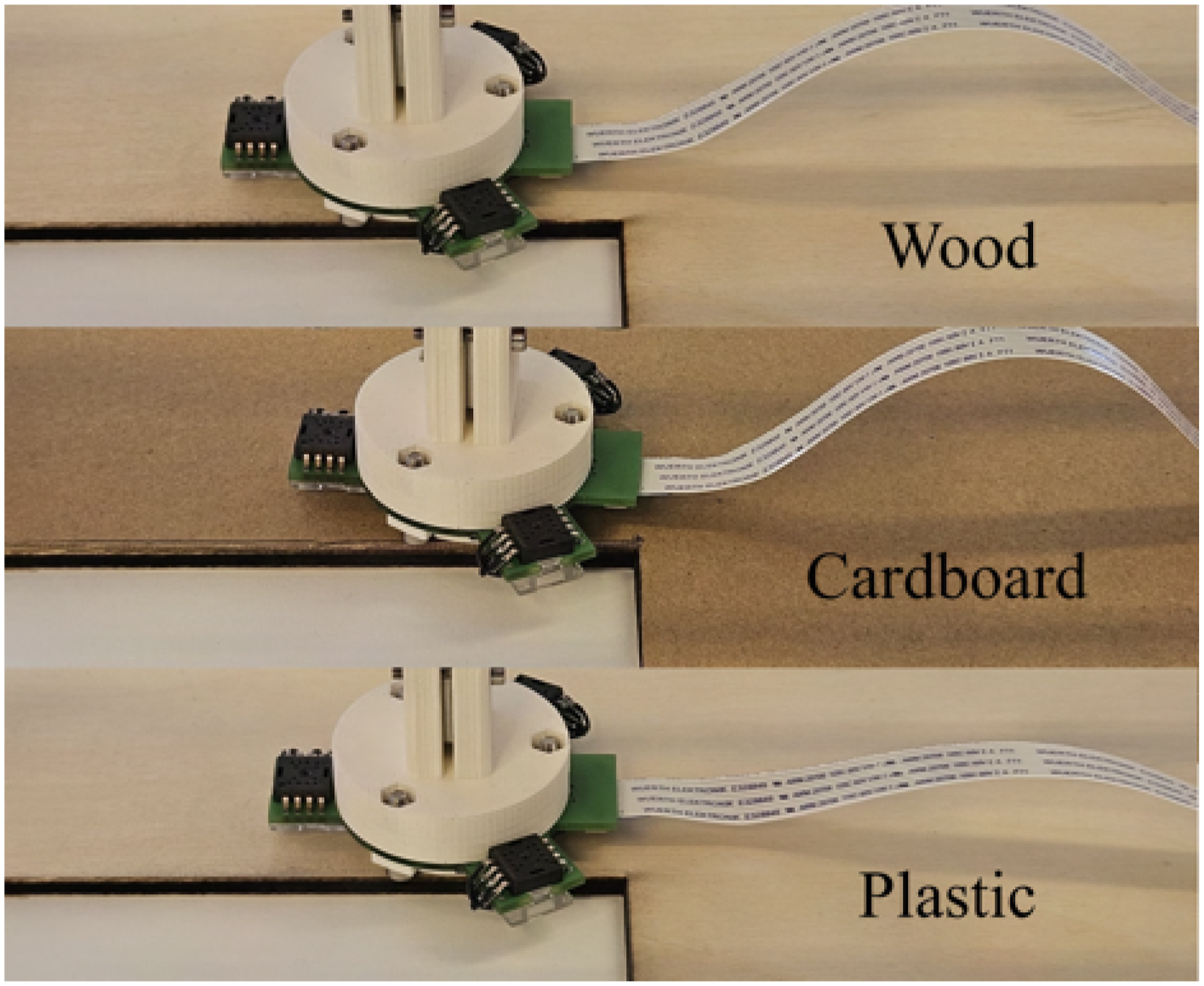
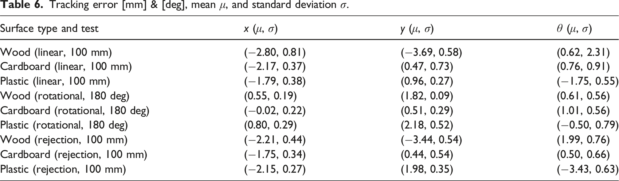
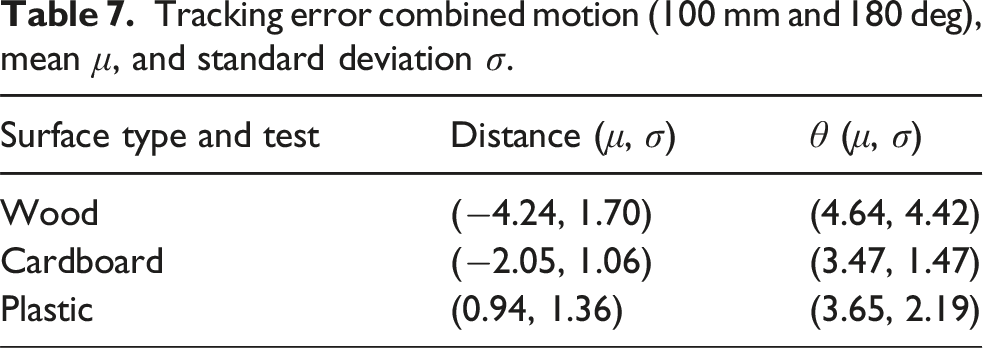
The findings indicate that the sensors tracked well across all tested surfaces, with the velocity integrating to approximately a 2% displacement error over a 100 mm distance. The estimation of angular velocity typically resulted in less than 1% displacement error. Notably, the sensor’s performance was not significantly disrupted when one of the sensors was outside the object, as demonstrated by the rejection test. Additionally, the sensor was capable of accurately estimating both angular and linear velocities simultaneously.
Estimation of contact properties
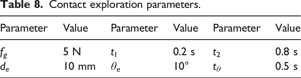
The contact estimation procedure was evaluated using four different objects: wood, a spectacle case, plastic, and cardboard, see Figure 17. The gripper, mounted on a UR10 robot (as shown in Figure 23), grasped each object with a 5 N force, see Table 8 the contact exploration parameters. The procedure began with a linear exploration to estimate μ
s
, μ
c
and μ
v
, see Figure 23. Following the linear exploration, the gripper executed the rotational exploration, see Figure 24. The estimation process, as detailed in Section Estimation of contact properties, was repeated 10 times for each object, with the mean and standard deviations presented in Table 9. Linear exploration movement for friction estimation. Contact exploration parameters. Rotational exploration movement for contact radius estimation. Estimation of contact properties, mean μ, and standard deviation σ, ⋅(i) is for sensor i.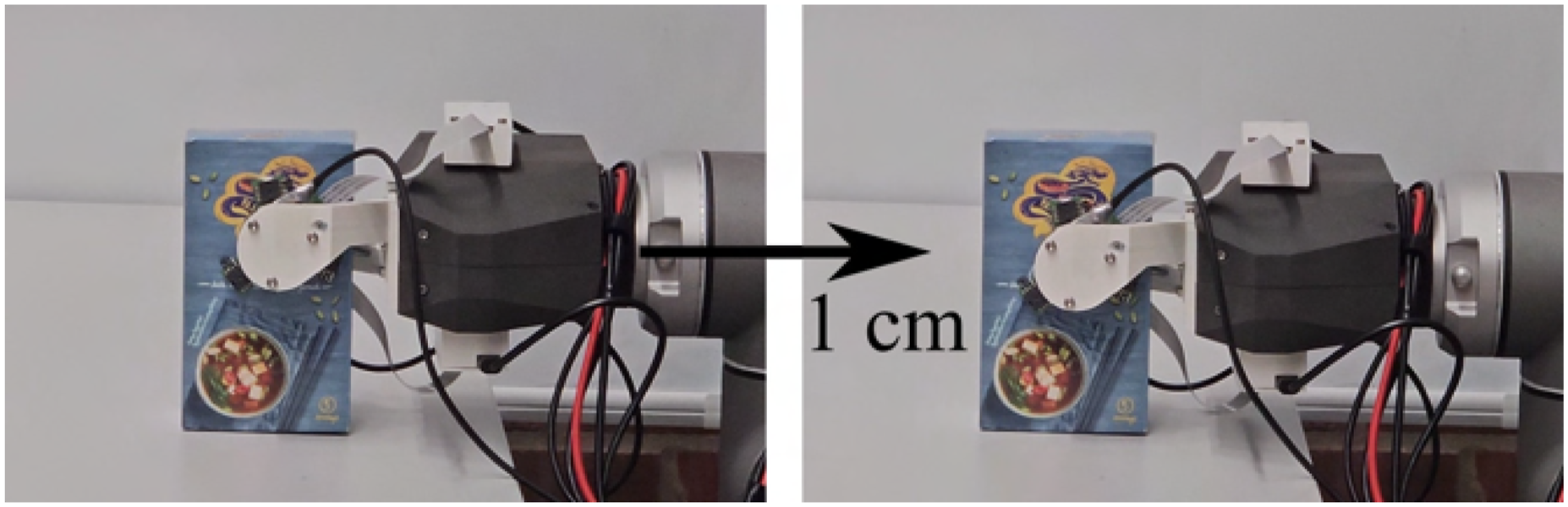
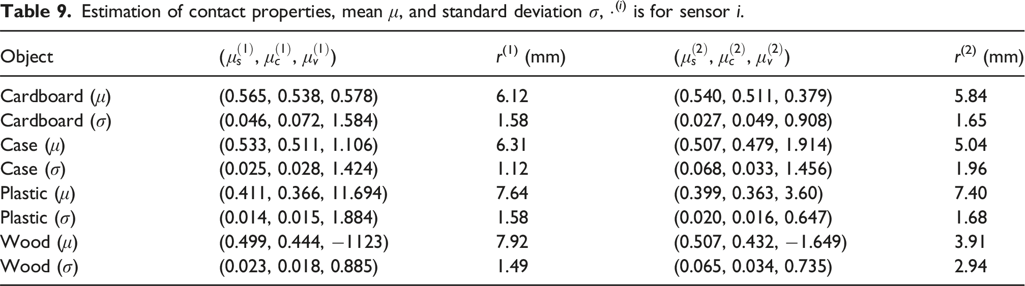
The experiments demonstrate that the gripper and sensor combination can estimate friction coefficients and contact radius in just 2 s of exploration. The procedure relies solely on in-hand sensing, without depending on the robot’s forward kinematics. As shown in Table 9, both sensors produce similar friction coefficient estimates for the same material and object. The results reveal variations in friction coefficients across different objects, with cardboard exhibiting the highest friction and plastic the lowest. Notably, the viscous friction varies significantly between objects, and it is important to mention that the gripper’s average velocity during exploration is only 0.0125 m/s and that the viscus friction estimate might only be accurate within the explored velocity range.
The actual contact surface radius is 15 mm, and under the assumption of uniform pressure distribution, the equivalent rim contact radius would be 10 mm. However, the estimated rim contact radius is lower than the theoretical value for all objects. This discrepancy is mainly attributed to two factors: object surface deformation and finger flexion. Each object deforms differently under grasping, and since the gripper’s contact pads are rigid, the assumption of uniform pressure distribution may be weak. The finger flexion during grasping is attributed as the primary factor influencing the results. Because the contact surface is rigid, even slight misalignment due to finger flexion or other causes can significantly impact the pressure distribution, as illustrated in Figure 25. This phenomenon particularly affects rigid objects more than deformable ones, as finger flexion reduces the contact area and limits the torque that can be generated. Illustration of finger flex under higher grasp force.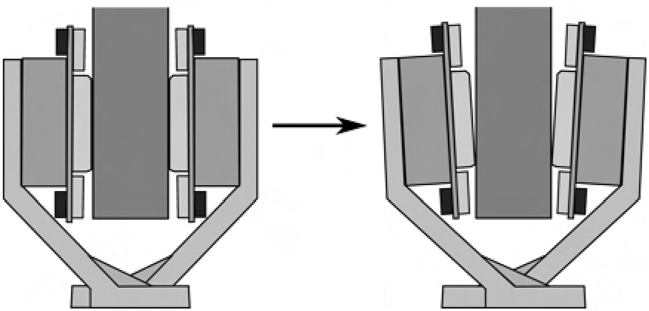
Slip-avoidance
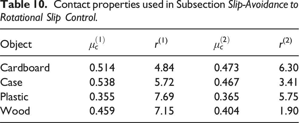
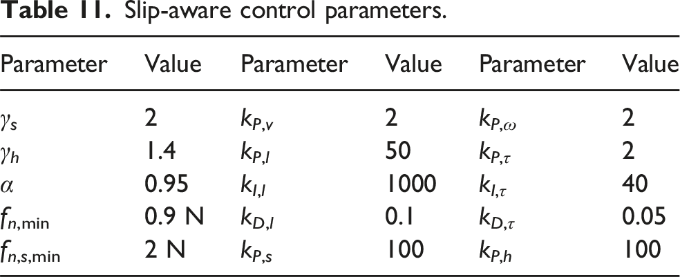
The slip-avoidance controller is designed to prevent slippage by dynamically adjusting the grasp force in response to disturbances. To evaluate its effectiveness, an object was grasped while various disturbances were introduced, as depicted in Figure 26. The most recently estimated contact properties from the experiments in Subsection Estimation of Contact Properties were used, see Table 10. The parameters for the slip-aware controllers, tuned through experimentation, are presented in Table 11. Disturbances to test the slip-avoidance controller, position 9 and 10 in the figure illustrate dropping a weight on the grasped object. The corresponding forces are presented in Figure 27. Contact properties used in Subsection Slip-Avoidance to Rotational Slip Control. Slip-aware control parameters.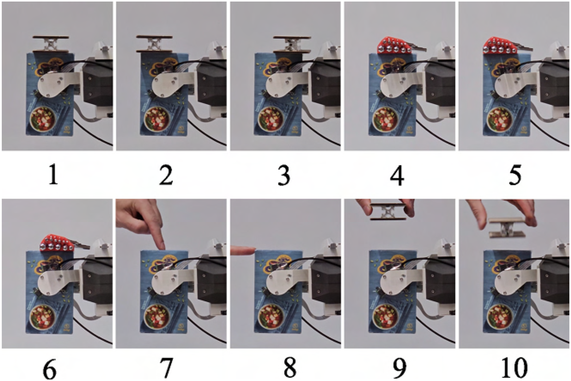
The first disturbance involved adding a 141 g weight on top of the grasped object, followed by placing the weight on either side to create a torque disturbance. The resulting forces are shown in Figure 27. When the weight was placed on the side of the object, the grasping force f
n
increased to compensate for the additional torque. Subsequently, a heavier weight of 727 g was placed on the object, as illustrated in positions 4 to 6 in Figure 26. The slip-avoidance controller responded by increasing the grasp force to compensate for the added weight. When the heavier weight was placed on the corner of the object, the grasp force reached its maximum, as seen in Figure 27. Following this, a manual disturbance was introduced, as shown in positions 7 and 8 in Figure 26. Finally, to enforce slippage, the 141 g weight was dropped onto the grasped object, causing a sudden acceleration, depicted in positions 9 and 10 in Figure 26. This sudden impact resulted in a spike in the grasp force until the object decelerated. The corresponding linear displacement x, as measured by the velocity sensors, is also presented in Figure 27. The experiment demonstrates that the slip-avoidance controller effectively adjusts the grasp force in real-time to prevent slippage, even under varying and sudden disturbances. Forces and tangential velocity from the slip-avoidance controller.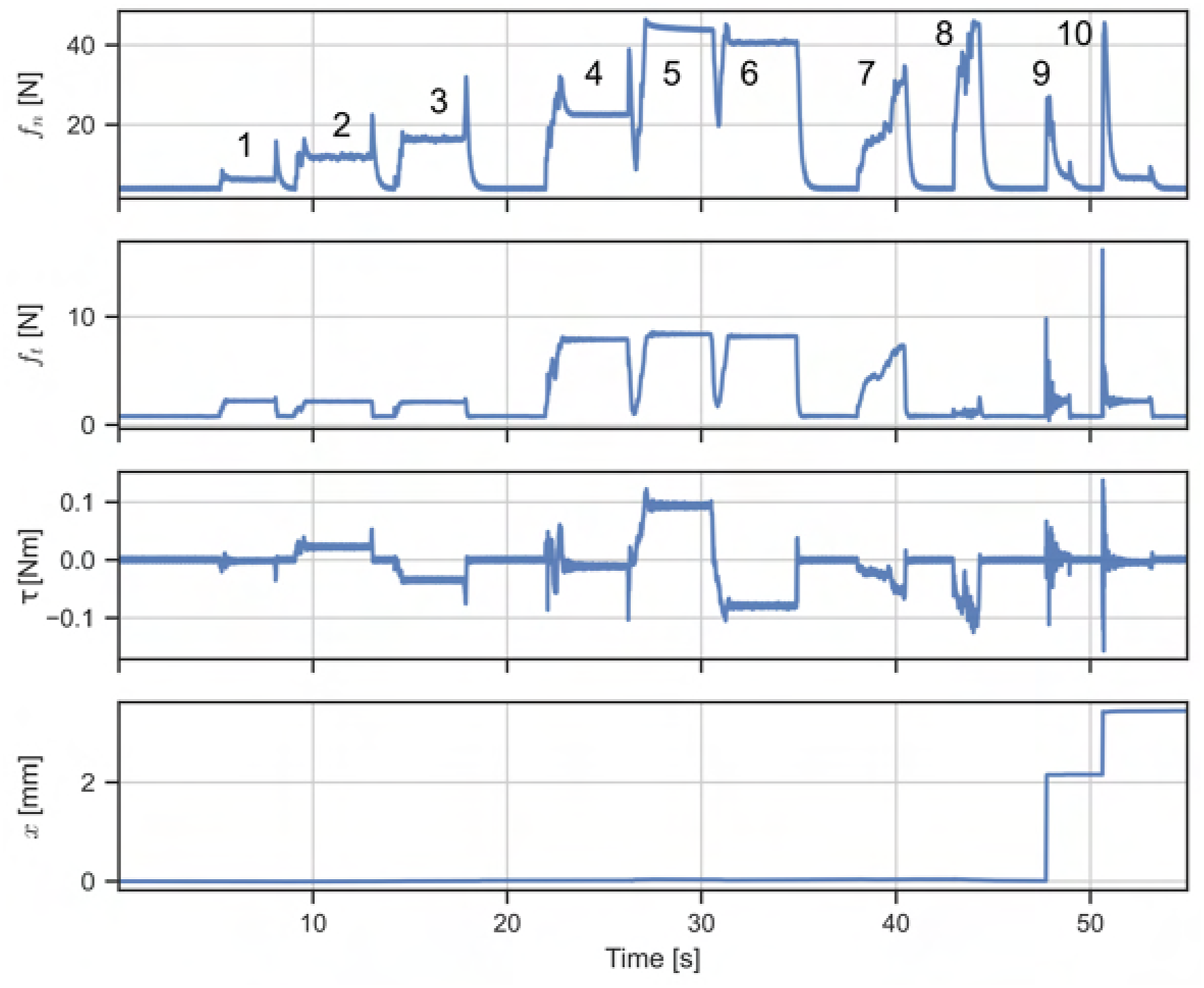
Linear slip control
The linear slippage controller was evaluated through four different experiments for each of the objects listed in Table 10. The estimated contact properties and control parameters used are provided in Tables 10 and 11, respectively. The experiments were designed to assess the controller’s performance across a range of target displacements and slippage velocities: (1) 20 mm linear displacement in 2 s. (2) 20 mm linear displacement in 5 s. (3) 40 mm linear displacement in 2 s. (4) 40 mm linear displacement in 5 s.
Snapshots from these experiments are shown in Figures 28(a) and 28(b). The controller followed a trapezoidal trajectory, with both the trajectory and internal displacement estimation presented in Figure 29 from two of the tests. The results demonstrate that the linear slip controller can achieve the desired final displacement; however, it experiences the stick-slip phenomenon during trajectory following. Snapshots of linear slippage experiment with cardboard object. Linear slippage: top plot follows a 20 mm trajectory for 5 s and bottom plot shows a 40 mm trajectory for 2 s. 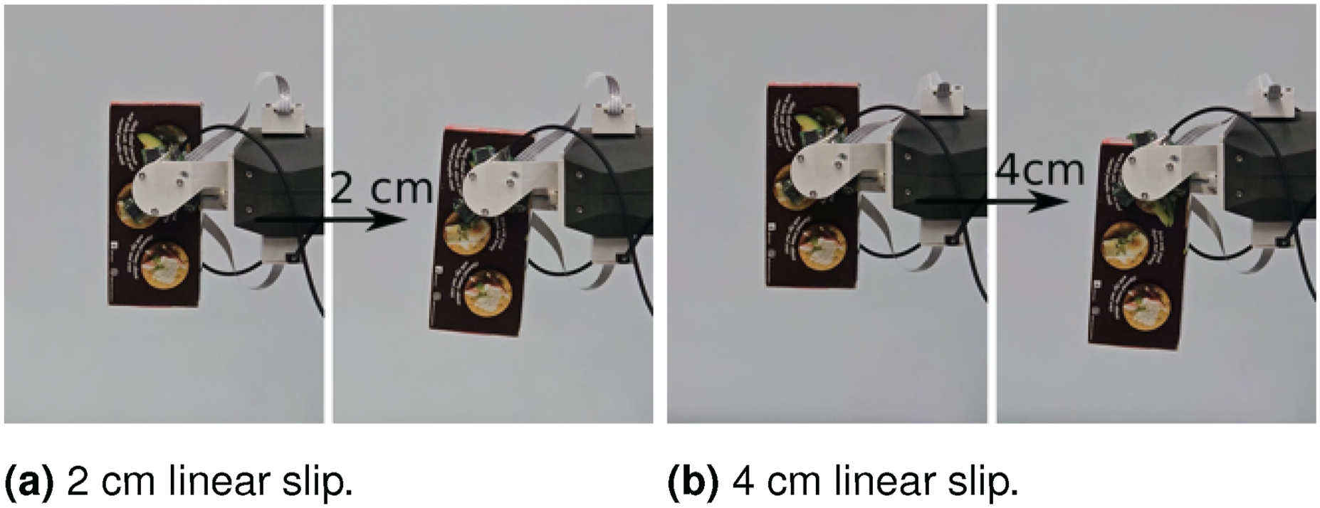
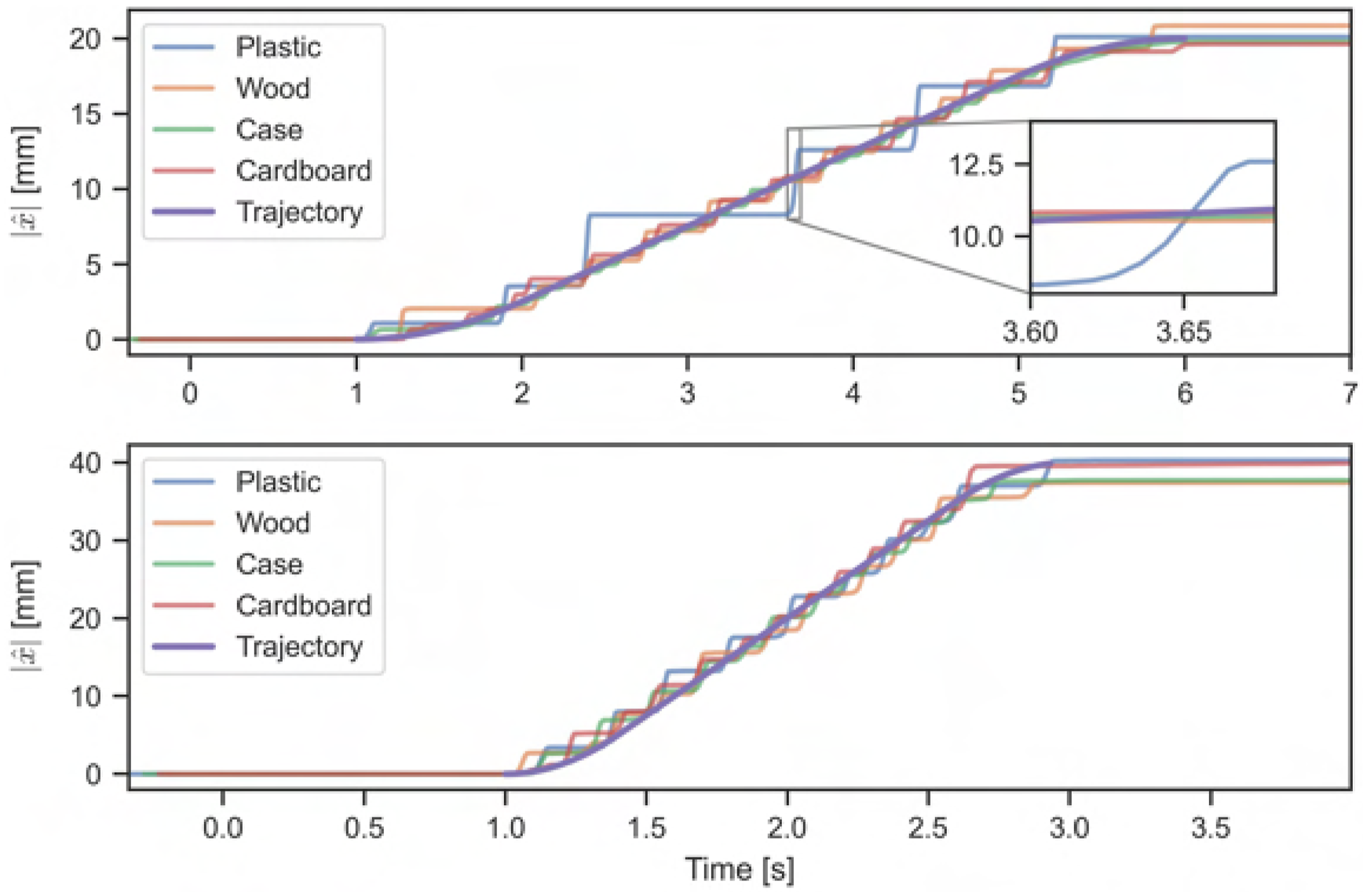
The entire slip-to-stick event can occur within 0.05 s, as shown in Figure 29. When the object transitions from sticking to slipping, the friction force shifts from static to Coulomb friction, resulting in rapid acceleration. As the rigid contact pad provides minimal damping compared to soft fingers, the object’s sliding velocity and acceleration become highly sensitive to the grasp force and contact properties. This sensitivity can cause the object to overshoot the intended trajectory upon slipping, leading the linear slip controller into a stick-slip cycle. Figure 30 illustrates two extremes in surface material behavior. The spectacle case with synthetic leather shows relatively smooth velocity transitions, with only minor adjustments to the grasp force. In contrast, the plastic object quickly overshoots the trajectory, triggering pronounced stick-slip motion, which is reflected in the grasp forces. Notably, the plastic object exhibits a larger difference between the static and Coulomb friction coefficients compared to the spectacle case (see Table 9), contributing to the pronounced stick-slip behavior observed during the experiment. Highlights the two extremes in stick and slip phenomenon between the plastic and case object, with the associated measured grasp forces.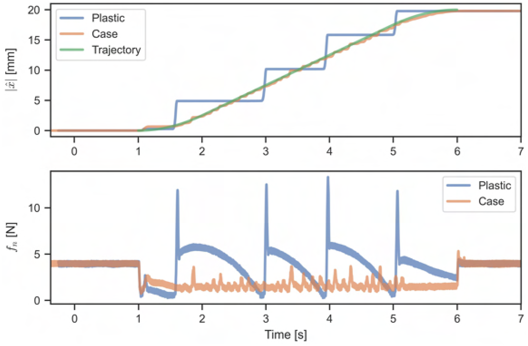
Linear slippage, distance x traveled, mean μ, and standard deviation σ.
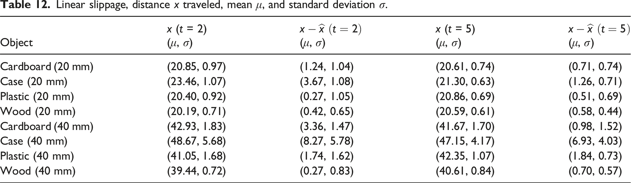
The synthetic leather case was a notable outlier, as it on average overshot the target displacement significantly further than the other objects. As shown in Table 12, this overshoot can be attributed to tracking inaccuracies, where the sensors underestimated the actual distance traveled. However, the tracking accuracy for the spectacle case improved at slower velocities, such as 20 mm in 5 s. It should be noted that during the 40 mm in 2 s experiment, there was one instance where the spectacle case fell out of the gripper.
Rotational slip control
The rotational slip controller leverages gravity to reorient the object by following specific trajectories, which were evaluated under different target displacements and velocities: (1) (2) (3) (4)
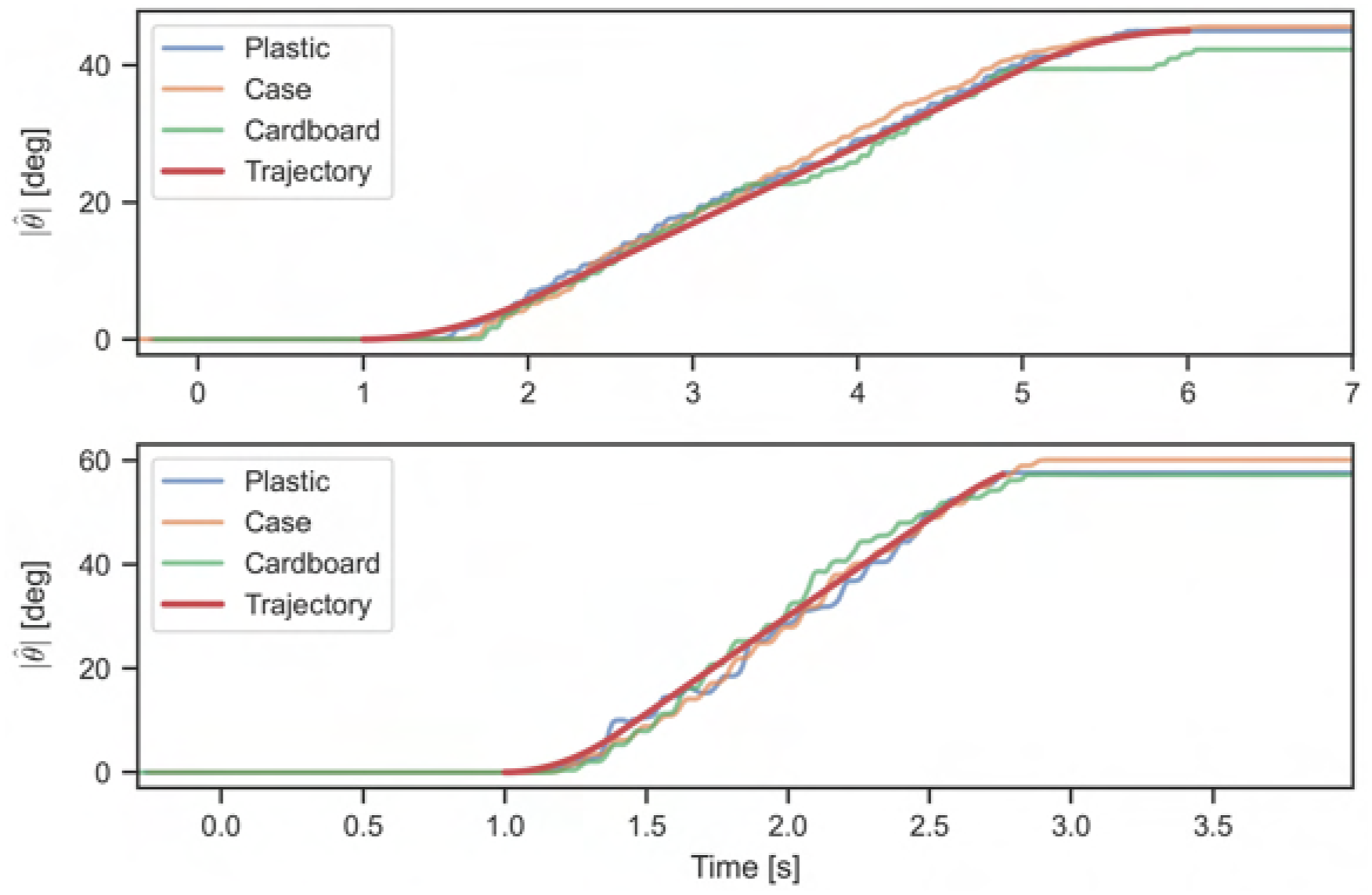
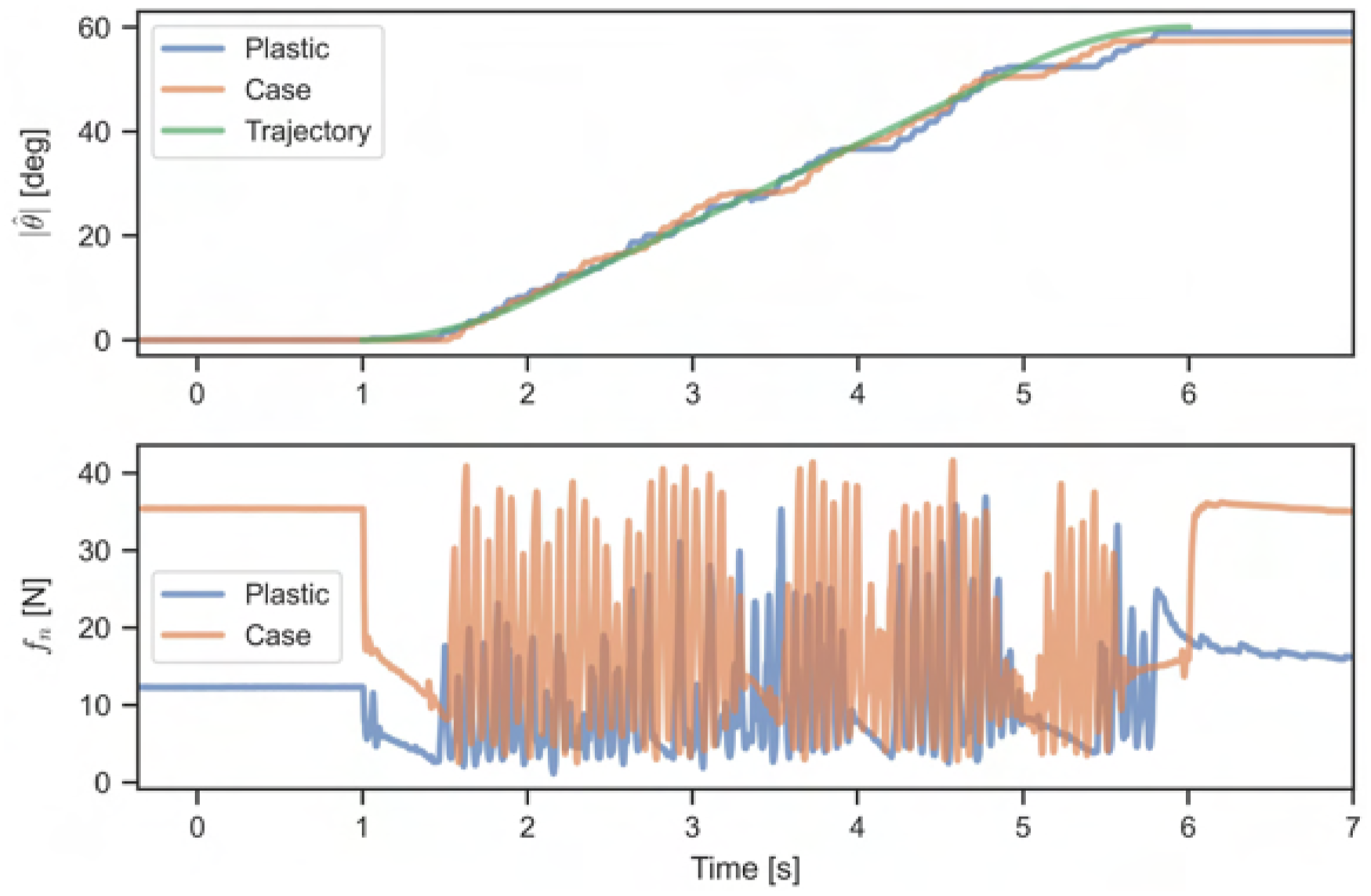
The initial and final poses of the rotational slip experiments are shown in Figures 31(a) and 31(b). The internally measured rotational displacements compared to the desired trajectories are presented in Figure 32. The trajectory following in the rotational slip experiments appears smoother compared to the linear slippage experiments; the slip-stick motion is less pronounced. This smoother response can be partially attributed to the limited control authority for generating torque. The grasp forces between the linear and rotational slippage experiments differ significantly, as seen by comparing the forces in Figures 30 and 33. Higher grasp forces cause more pronounced finger flexion, reducing the effective surface contact area, as illustrated in Figure 25, which reduces torque. This finger flexion can result in a nonlinear torque response to the grasp force. However, it is worth noting that the grasp force oscillates more in the rotational slip experiments than in the linear ones. The parameters used for the rotational controller, listed in Table 11, were tuned for trajectory following rather than smooth grasp forces. Additionally, the wooden object saturated the rotational controller and was therefore not tested further. Snapshots of rotational slippage experiment. Rotational slippage for 45°, top plot shows a 5 s trajectory, and bottom plot shows a 2 s trajectory. Highlights the grasp force and trajectory following for the plastic and case object.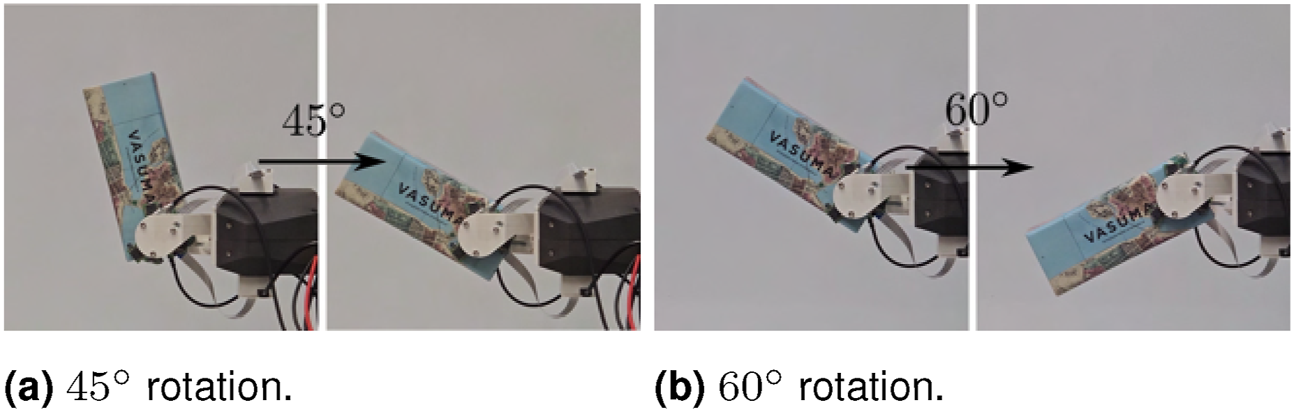
Rotational slippage, angle θ rotated, mean μ, and standard deviation σ.
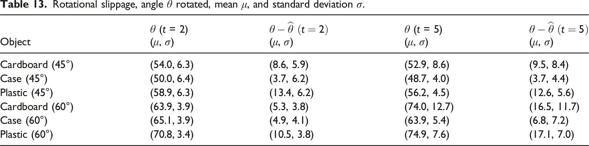
A higher grasp force increases finger flexion, which alters the distance between the sensor and the object surface. Optical mouse sensors are generally sensitive to vertical distance, potentially impacting accuracy. The authors attribute most of the tracking error to situations where multiple optical sensors are outside the object simultaneously. The current gripper design has limited space for accommodating object rotation without causing collisions, often leading to object placements where more than one sensor could be tracking outside of the object during the motion. When only one of three optical sensor accurately tracks velocity, displacement is likely to be underestimated.
Hinge control
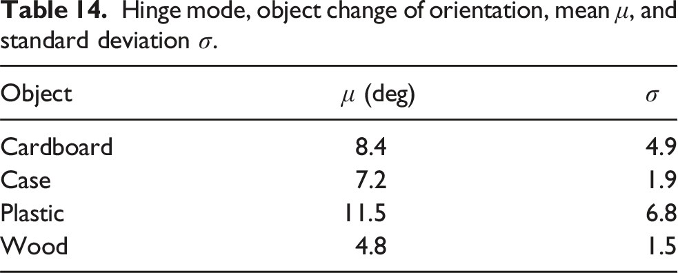
The hinge controller enables the gripper to rotate while keeping the CoG of the object directly beneath the grasp point, as shown in Figure 34. In the experiment, the gripper is initially rotated 30° away from the vertical axis, with the object hanging vertically from the gripper. The gripper, with hinge control activated, is then rotated 60° in the opposite direction, while the object is expected to remain in a vertical orientation. Hinge mode experiment.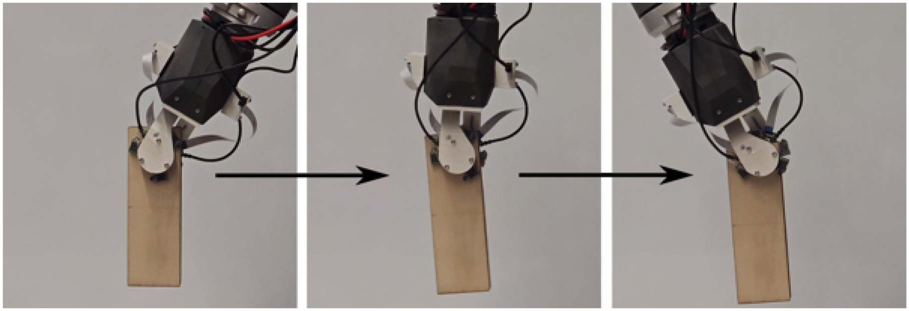
Hinge mode, object change of orientation, mean μ, and standard deviation σ.
Testing the limits
Two edge cases are evaluated: (i) the maximum speed at which an object can be repositioned within the gripper and (ii) the effect of surface curvature on performance. To simplify the analysis, only plastic objects are considered.
Testing the limits with plastic object for linear slippage of 20 mm with different trajectory times and surface curvatures. Distance x traveled, mean μ, standard deviation σ, and actual time t. A fail is considered if the object falls out of the gripper.
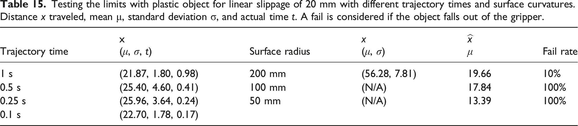
Case (ii): While the planar velocity sensors are optimized for flat surfaces, this experiment evaluates performance degradation with increasing surface curvature. The tested objects, shown in Figure 35, all match the weight of the plastic object in Table 3. Each object is commanded to slide 20 mm in 2 s, with results summarized in Table 15. As curvature increases, the velocity tracking progressively underestimates the true velocity. This degradation is attributed to the sensor moving away from its optimal sensing distance as the surface curves. On the 200 mm radius surface, the object fell from the gripper in one out of 10 trials and exhibited significant overshoot. For the 100 mm and 50 mm radius surfaces, the object fell out in all trials, with estimated displacements decreasing further as curvature increased. Plastic objects with curved surfaces.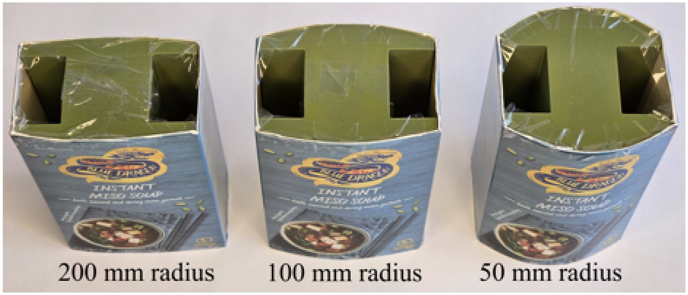
In-hand manipulation demonstration
The final demonstration integrates all of the proposed methods into a single cohesive performance, as shown in Figure 36. The sequence begins by grasping an object in a known pose, followed by the estimation of the contact properties. Once the object is securely grasped, the slip-avoidance controller is activated, and the object is lifted. Next, the linear slip controller is employed to move the object 30 mm downward over 3 s, after which the hinge controller is used to reorient the gripper relative to the object. The slip-avoidance controller then reorients both the gripper and the object, setting the stage for the rotational slip controller to rotate the object by 30° within 3 s. In-hand manipulation demonstration.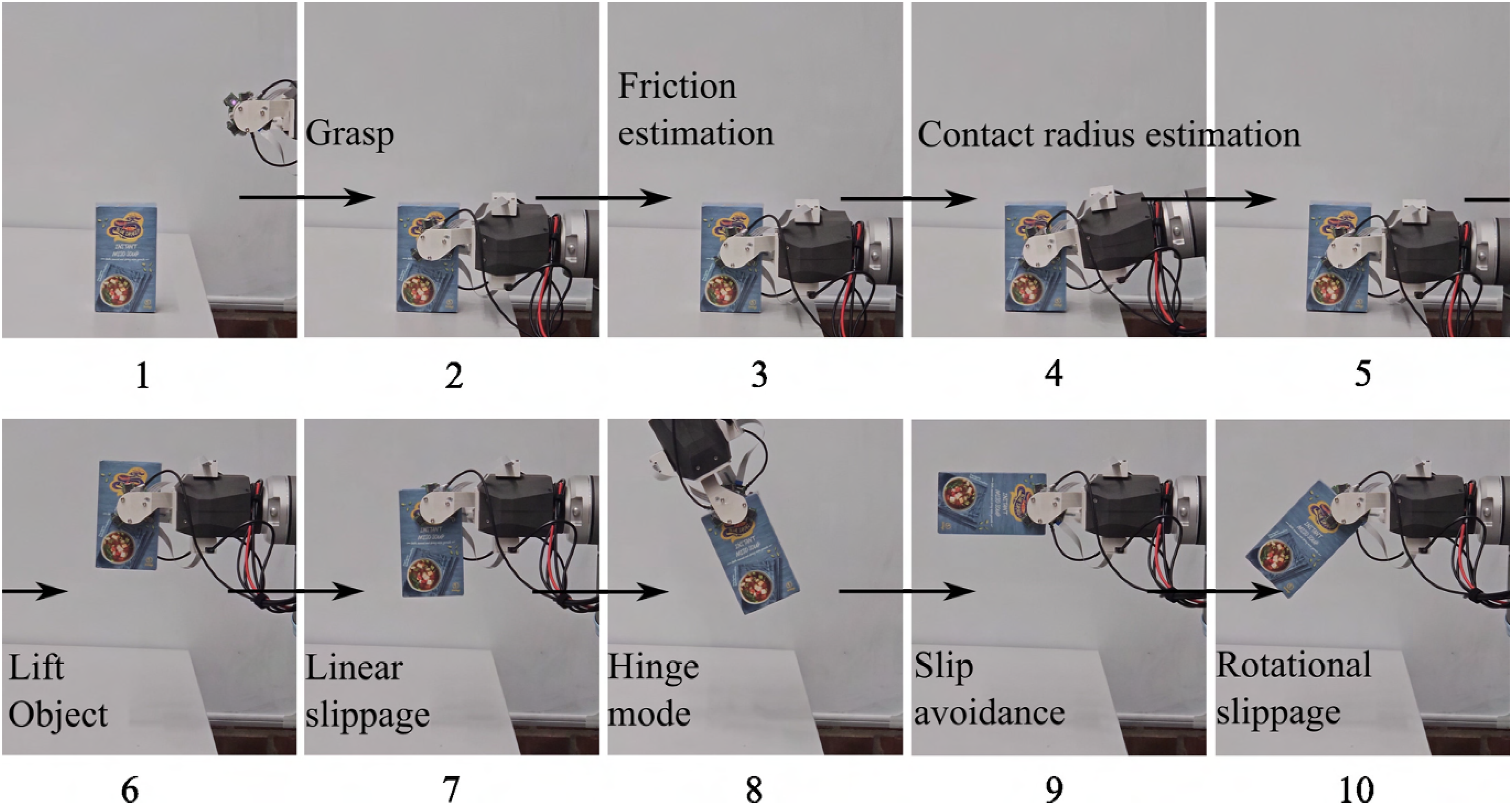
This demonstration was conducted 10 times using the plastic object, and successfully performing all tasks 9 times without dropping the object, achieving a 90% success rate. The demonstration highlights the capabilities of the proposed system and illustrates how gravity-assisted slip control can endow parallel jaw grippers with the ability to manipulate an object and change the gripper-object configuration.
Conclusions
In this paper, we have presented a comprehensive system for advanced in-hand slip control, featuring several key components: a parallel gripper that enables fast and precise force control, relative velocity sensors mounted on force-torque sensors that accurately measure both tangential and rotational velocities, and a fast contact property estimation process. Additionally, we introduced four slip-aware controllers: slip-avoidance, trajectory-following for linear and rotational slippage, and hinge control. The gripper, equipped with these sensors, was mounted on a UR10 robot, and our system was rigorously tested across a wide range of scenarios. The results demonstrate that using solely in-hand sensing, our approach advances the state of the art for in-hand slip control.
This study demonstrates the significant potential of the proposed hardware system. However, our immediate focus will be on enhancing the sensing capabilities and improving the physical contact properties to relax the constraint of parallel surfaces or a rigid contact pad, thereby enabling interaction with more complex object geometries. Beyond this, the research could branch into various promising directions. For instance, future work could explore dynamic movements and manipulation, smoother slippage control, online friction estimation, extend the effective reach of manipulators, slip-aware multi-arm manipulation, manipulation based on external contacts, sensor fusion with external sensors, planning for slip-aware systems, and advancing human–robot interactions.
Supplemental Material
Footnotes
Funding
Declaration of conflicting interests
The authors declared no potential conflicts of interest with respect to the research, authorship, and/or publication of this article.
Supplemental Material
Supplemental material for this article is available online.
Note
References
Supplementary Material
Please find the following supplemental material available below.
For Open Access articles published under a Creative Commons License, all supplemental material carries the same license as the article it is associated with.
For non-Open Access articles published, all supplemental material carries a non-exclusive license, and permission requests for re-use of supplemental material or any part of supplemental material shall be sent directly to the copyright owner as specified in the copyright notice associated with the article.