
Abstract
Wrist mobility contributes significantly to the execution of upper limb motor tasks. Despite this, current prosthetic wrists are far less advanced than other artificial joints. Typically, prosthetic wrists offer limited degrees of freedom, if any, which forces users to execute compensatory movements during task performance. This addition increases weight and complexity, two unwelcome factors in upper limb prostheses. This article presents the design of a 3-degree-of-freedom friction-lockable prosthetic wrist actuated by a single motor. The design features adaptable behavior when unlocked, promoting a gentle interaction with the environment, and enables users to adjust the hand configuration during pre-grasping phases. The proposed system was tested, combined with a hand prosthesis, and compared to a commercial rotational wrist during the execution of functional movements. Experiments involved nine able-bodied subjects and one prosthesis user. Participants also performed the experiments with their biological wrist (the intact wrist for the prosthesis user) as a control. Results showed that the lockable wrist was used actively 20% more often than the commercial solution without compromising users’ execution time. Interaction tests reveal that compensatory movements are reduced when using the proposed design, resulting in closer resemblance to the control wrist’s performance. The average satisfaction and usability scores were significantly higher for the proposed wrist, indicating its potential acceptance. Finally, the system was validated in a set of activities of daily living performed by the prosthesis user. The study contributes to the development of more intuitive and adaptable prostheses that can improve the quality of life of amputees.
1. Introduction
The development of arm prostheses is one of the most fascinating and open challenges in rehabilitation engineering. The limited performance of both human–machine interfaces (Oskoei and Hu 2007; Schultz and Kuiken 2011) and mechatronic solutions restricts the effectiveness of state-of-the-art prostheses. The deficit of compact and light actuators, combined with design trade-offs concerning the desired performance, prehension capabilities, and anthropomorphism, results in a reduced set of movements that current prostheses can accomplish (Controzzi et al., 2014). Furthermore, voluntary control over independent signals on residual limbs is scarce, which restricts users to control only a few degrees of freedom (DoFs) in active prostheses. Recent developments in myoelectric control have delved into the management of multiple DoFs by employing more advanced algorithms and/or an increased number of surface (Chen et al., 2023; Nowak et al., 2022) or intramuscular (Smith et al., 2015) EMG sensors, which gather supplementary data.
Prostheses often oblige their users to perform unnatural compensatory movements to recover their range of motion (Stavdahl 2002), produce larger forces (Zinck 2008), and recuperate an acceptable level of smoothness, accuracy, and energy efficiency (Todorov 2004). These movements increase the discomfort experienced when using robotic aids, hindering their acceptance (Davidson 2002). Furthermore, they often result in residual limb pain, musculoskeletal stress, and overuse syndromes that can lead to injuries in the long run (Gambrell 2008; Kidd et al., 2000; Østlie et al., 2011).
Although significant technological advances have been made in the design of dexterous prosthetic hands (Capsi-Morales et al., 2021), relatively little attention has been given to replacements for proximal joints, such as the wrist. The human wrist is responsible for orienting the hand in space during grasping and manipulation tasks, with three degrees of DoFs enabling flexion/extension (F-E), abduction/adduction (A-A), and pronation/supination (P-S) (Moser et al., 2020). By adjusting the hand position in accordance with the object’s shape and placement, the wrist plays a crucial role in executing these tasks (Figure 1). Montagnani et al. (2015) prove that a single DoF hand with wrist F-E allows functions comparable to a highly performant multi-DoF hand without a wrist. Besides, Kyberd (2012) suggests that an adaptive wrist with both compliant and rigid behaviors could benefit the user by alternating between featuring adaptability during the approach and stability during holding. Examples of human wrist configurations in common grasps: (a), (b) flexion, (c), (d) pronation and abduction, and (e) pronation and adduction.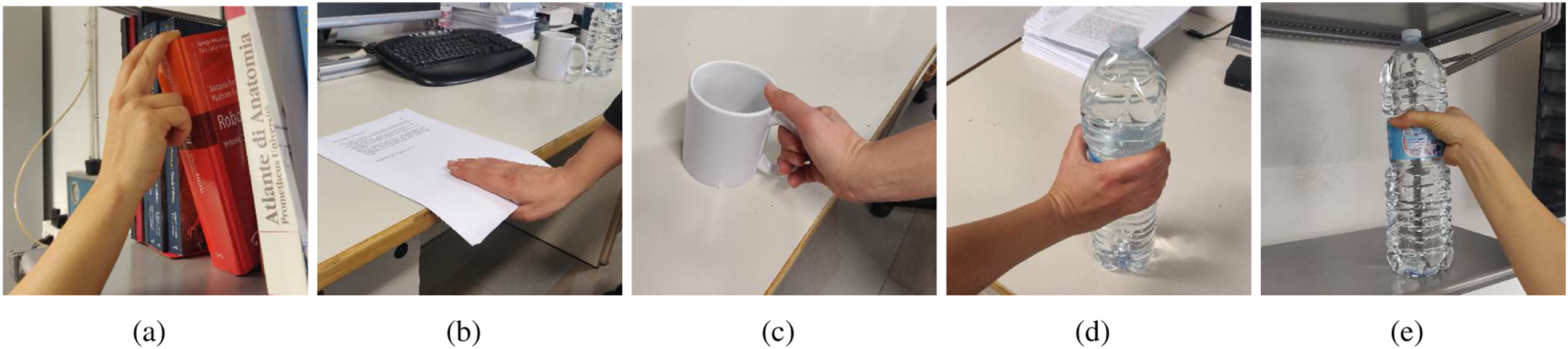
This paper presents the design of an innovative semi-active 3-DoF prosthetic wrist, which can switch between two states: (i) adaptable and (ii) fixed (or locked), through the use of only one motor. When unlocked, the wrist can be oriented in any configuration, featuring compliant behavior that favors the interaction with the environment. Contrary to other designs present in the literature (see details in Sec. 2), this solution permits the fixation of all 3 DoFs through a friction-lockable mechanism when a desired configuration is reached. The proposed design allows the physical adjustment of the prosthetic hand orientation (e.g., during the pre-grasping phase) and the regulation of its stiffness, based on a simple myoelectric control strategy. This prosthetic wrist aims to (i) reduce compensatory movements of proximal joints and (ii) facilitate the reach and holding phases of the grasp. Furthermore, this design lets us investigate the functional capabilities of a prosthetic wrist with an enlarged range of motion, specifically in tasks that require proper hand orientation. To do so, we compare the proposed design to a commercial pronation/supination rotator, which is the most common type of active wrist. The comparison uses time-based metrics, biomechanical measures, and self-evaluation surveys. The experimental evaluation combines each of the two wrists with the same prosthetic hand. We tested nine intact volunteers and one subject with a congenital malformation at the transradial level (Figure 2). Results proved the feasibility and potential of the proposed wrist. Prosthesis user wearing (a) her own esthetic prosthesis and (b) the proposed 3 DoFs wrist system.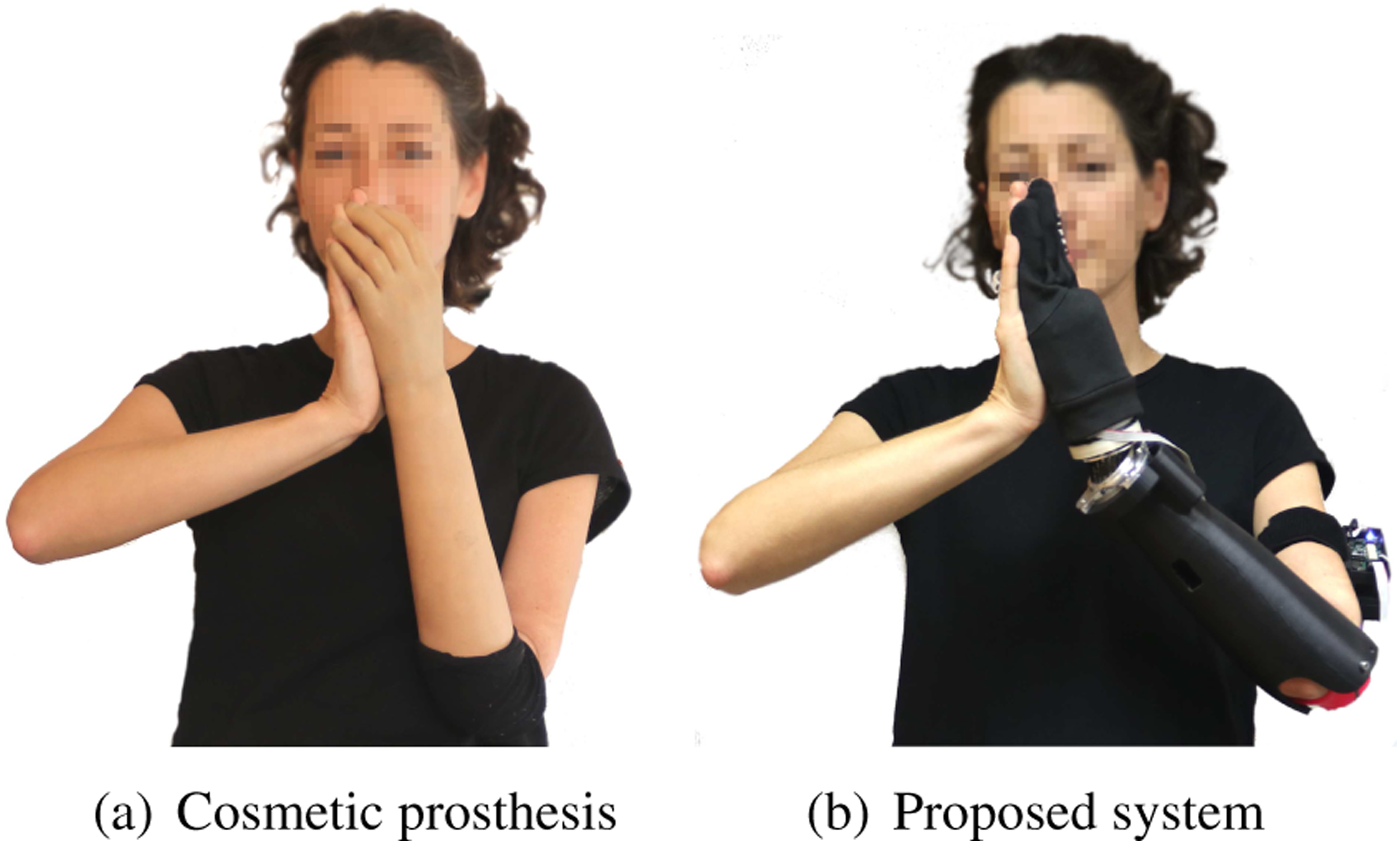
2. State of the art
The wrist represents an essential constituent of the hand-arm system in humans, whether it is natural or artificial. Jacobs (1993) showed that passive prosthetic wrists improve the reaching and grasping abilities, substantially reducing or entirely preventing compensatory movements. Accordingly, the orthopedic prosthetics market offers several passive wrists, where the user manually adjusts the configuration of the wrist during or previous to task execution. Unfortunately, function of passive wrists is limited when manipulating with both hands (Sears et al., 2005). Looking for compliant wrists (Bajaj et al., 2015), the only few solutions available on the market offer 1-DoF (flexion/extension) or 2-DoFs (flexion/extension and abduction/adduction). Slightly more advanced solutions include compliant wrists that use torsional springs to hinder the movement when the hand grasps heavy objects. Finally, a spherical joint for children prostheses (MyolinoWrist, Ottobock) presents different levels of friction that the user can set manually for a continuous flexion of the hand. Alternatively, the orthopedic market features active solutions designed to improve arm dexterity. Unfortunately, those are still extremely basic and the user has to use non-intuitive switching control techniques to command one DoF at a time. The most common active wrist is a 1-DoF rotator module that restores the prono/supination movement. Metzger et al. (2012) proved that this restoration decreases the compensatory movements in transradial prosthesis users.
Even in research, there is modest progress in the field of prosthetic wrists design. The RIC Arm (Lenzi et al., 2016) uses active serial 2-DoF to impart pronation and flexion to the terminal device. The solution in Fite et al. (2008) presents a parallel 3-DoF gas-actuated architecture. Bajaj and Dollar (2018) presented an alternative composed by 2-DoFs parallel mechanism and a belt-driven serial mechanism for continuous pronation. Other solutions explore more compact and compliant structures with multiple DoFs (Demofonti et al., 2023; Lee et al., 2021). For a complete review, please refer to Bajaj et al. (2019). Research is also scant when looking at the issue of measuring the impact the wrist joint has on the overall capabilities of a prosthetic limb. Bertels et al. (2009) showed that coupling a conventional prosthetic hand with 1-DoF wrist reduces the extent of compensatory movements required to reach objects. Some studies compare the performance of stiff versus compliant wrists during Activities of Daily Living (ADLs) (Deijs et al., 2016; Deijs et al., 2016; Petersen 2008). Although both of these approaches have limitations, these studies show that the adaptive capabilities of compliant wrists improve the function of prostheses, especially in bimanual manipulation. Kyberd (2012) compares different wrists combined with a traditional 1-DoF hand. Results demonstrated that while stiff wrists force individuals to perform significant compensatory movements during the reaching phase, compliant wrists were unpractical while manipulating heavy objects.
Recent preliminary studies worked on the insertion of lockable passive wrists for prosthetic applications. Montagnani et al. (2013) presented a wrist prototype that exploits two polymeric elements as springs to select compliance and a bevel gear differential mechanism to orient the end effector in 2-DoFs. However, the stiffness selection was only possible with the wrist and hand axes in alignment, limiting the stiff mode only to holding objects straight. The same concept, adapted to hydraulically actuated body-powered hand prostheses, was presented in Montagnani et al. (2017). There, a unique master hydraulic cylinder drove the hand–wrist system. When the hand closes, the pressure of the hydraulic circuit changes to disable the flow in the wrist circuit through suitable valves, switching the wrist from free to locked in a certain configuration (continuous locking). The main drawback is the connection of both circuits, which does not allow independent control of the wrist and hand, limiting the wrist functionality to orienting for a better approach of the object. Likewise, Cappello et al. (2022) presented a 2-DoF wrist with a hemispherical unidirectional ratchet mechanism that automatically switches impedance when grasping and can completely lock only when the pin engages the central plughole at the rest position.
3. Friction-lockable wrist
3.1. Preliminary design considerations
We design a dexterous yet compact system for transradial prostheses that combines the benefits of compliant and rigid wrists. Our objective is to add 3 DoFs to the prosthetic limb to increase grasping dexterity and user’s autonomy. That would let us study the impact that a larger range of motion have on the overall prosthetic functionality. Moreover, inspired by Kyberd (2012) and Montagnani et al. (2017), we include passive adaptability and switchable impedance. We believe those latter two features would let the user pre-orient the hand intuitively by exploiting the environment and in a more stable fashion.
Because of the wrist role in prehension, we require its control to be simple and independent of the hand. Therefore, the wrist mechanism should switch from an adaptive state to a fixed joint configuration by locking and unlocking. The control of the single discrete Degree of Actuation (DoA) for locking and unlocking should depend on a myoelectric control scheme that does not compromise the hand motions.
We foresee two main types of application scenarios. In the first scenario, the user reaches a light object taking advantage of the adaptable wrist behavior. Therefore, the wrist is adaptive during the reaching phase. Afterward, the wrist locks (if desired) to give support and precision during the holding phase. The second scenario accounts for those cases in which the preshaping of hand orientation is fundamental to ensure the success of the grasp. These latter cases require the wrist rigidly fixed in the right position during reaching, to guide the approach to the object. The wrist stays locked during the holding phase as well.
To obtain a compact design of a 3-DoF joint lockable in all directions with only one actuator, we inspected several technologies in the literature. Nonetheless, a lot of the already existing options have issues with the size (Brown et al., 2010), the constant high power input requirements (Telleria et al., 2009), or exhibit a design that compromises our requirements (Palpacelli et al., 2014). Finally, the simplicity and compactness of a friction-lockable spherical joint for industrial applications (Alvin 2011) inspired our prototype design for a prosthetic wrist with switchable impedance properties.
3.2. Mechanical design
Figure 3 shows the proposed wrist design. Its general shape is cylindric for easy placement inside the prosthetic socket, aligned with the longitudinal forearm axis. The wrist consists of a spherical joint encased between two rings used to modulate the friction force on the sphere that constrains its rotation in the current orientation. A more detailed description on this concept and design is reported in Capsi-Morales et al. (2022). Mechatronic design of a 3-DoF wrist joint that can switch impedance in any configuration through just one motor. The circled section highlights the components from the compliant interface in flexion/extension and abduction/adduction together with the hand interface. The red bearing allows free pro/supination, while the pink elastic wires provide a natural interaction of the hand with the environment and humans.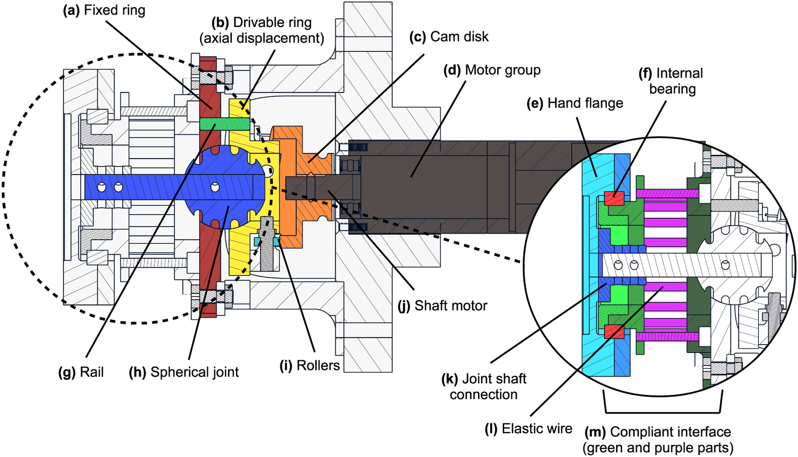
One of the rings can move axially relative to the other one fixed to the socket interface
The un-hindered displacement of the two rings would be ∼1.5 mm, which is small compared to the sphere radius (10 mm). Therefore, we model the friction force generation mechanism as

A MAXON DC-X 22s 24 V motor drives the displacement h
t
of the ring

The value Geometric representation of the cam movement: Vertical displacement with a triangular cam shape (constant step) (a) and motor axis rotation (b).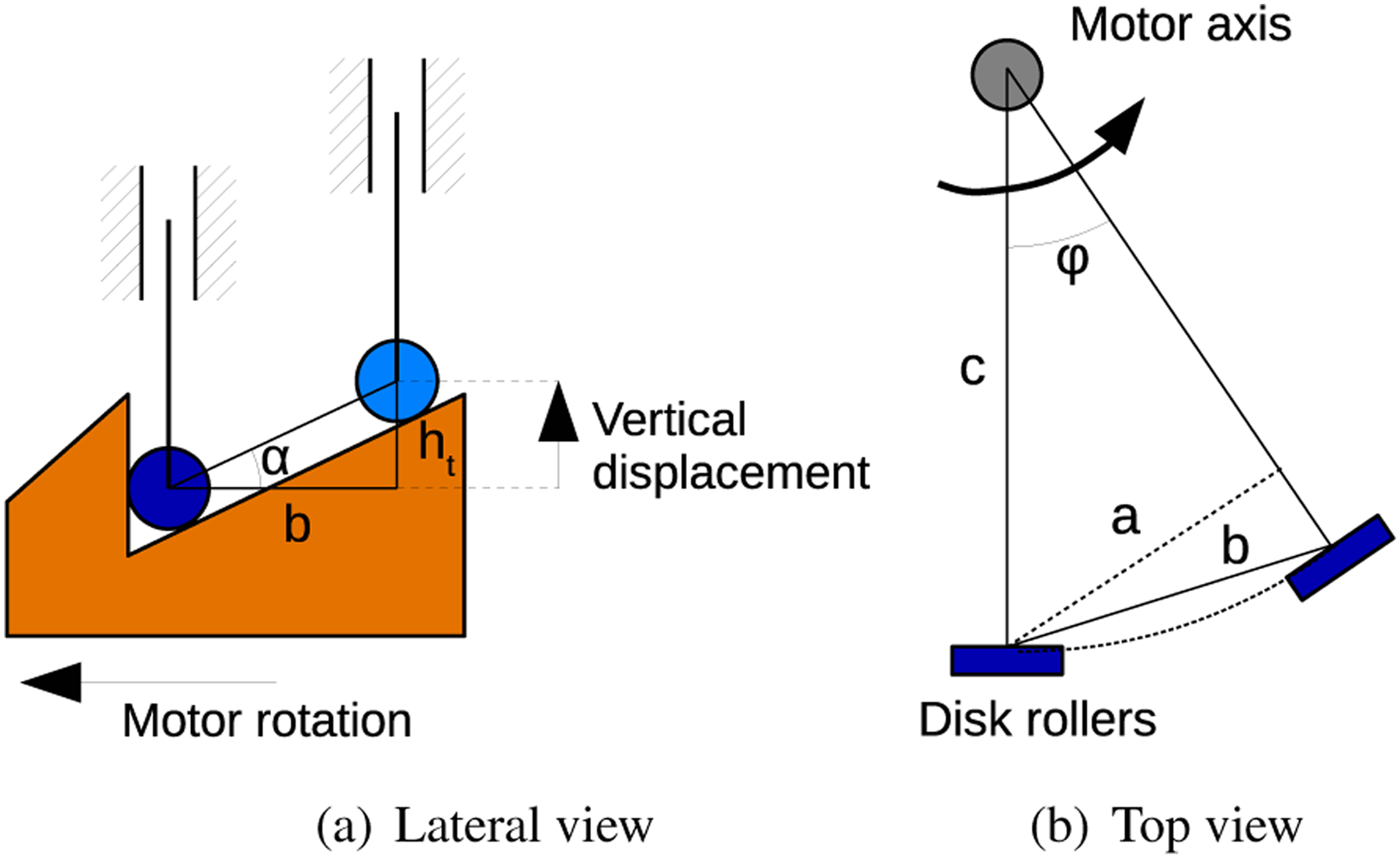


The structure of the sphere
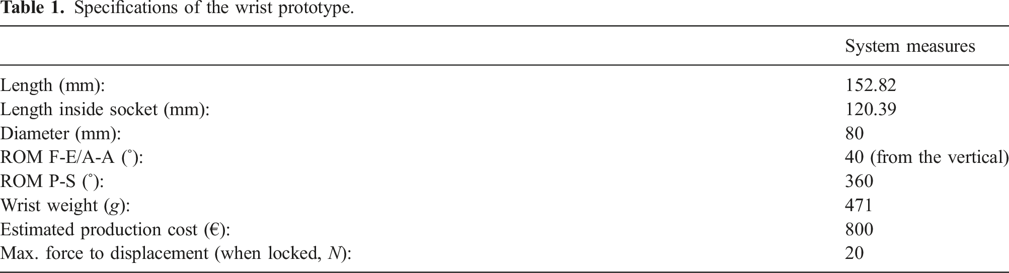
We designed and manufactured the wrist and all the pieces needed to evaluate its performance with a prosthetic hand, including the prosthesis user’s socket. Some of the most critical components are the sphere and the rings since they are always in contact and subject to high forces. Therefore, they are in aluminum. Other components that are subject to large forces are the cam disk and rollers. Therefore, the cam disk is in steel, and the rollers are in brass, impeding the plastic deformation of the rollers. The rest of the components are 3D printed in ABS plastic.
Specifications of the wrist prototype.
3.2.1. Compliant interface
The final component of our wrist system is an elastic component placed in parallel to the spherical joint. Its function is to obtain a more natural appearance and interaction with the environment during the adaptable state (see Figure 5). This elastic component should provide the system with progressive compliance in F-E and A-A while leaving P-S motions practically free. The rationale for this selection is that the moment generated by the eccentricity of the Center of Mass (CoM) of the hand with respect to the P-S axis is typically smaller than around the other axes. Also, the P-S articulation represents a pivotal DoF in amputees to minimize compensatory movements (Bertels et al., 2009), which is often used at non-zero angles. For these reasons, and using indications from users in a preliminary design study which showed their preference for this solution, we preferred to introduce an adequate level of friction on the P-S articulation just to prevent unintended rotations, while we use a moderate elastic torque τ
k
on the F-E and A-A axes. The compliant flange Adaptive behavior of the wrist on each DoF. τ
k
refers to the pulling torque that the compliant interface exerts towards the longitudinal forearm axis. This position is termed as rest position of the hand and is defined by the alignment of the hand flange and the shaft of the motor. Note that for pronation–supination, the hand can rotate freely with τ
k
≈ 0. When the hand is grasping an object or interacting with the environment, the wrist can exhibit a different behavior only if τ
e
> τ
k
, where τ
e
is the torque executed by the environment. Contrary to other lockable systems present in the literature, the proposed system can fix all DoFs at any configuration with only one motor.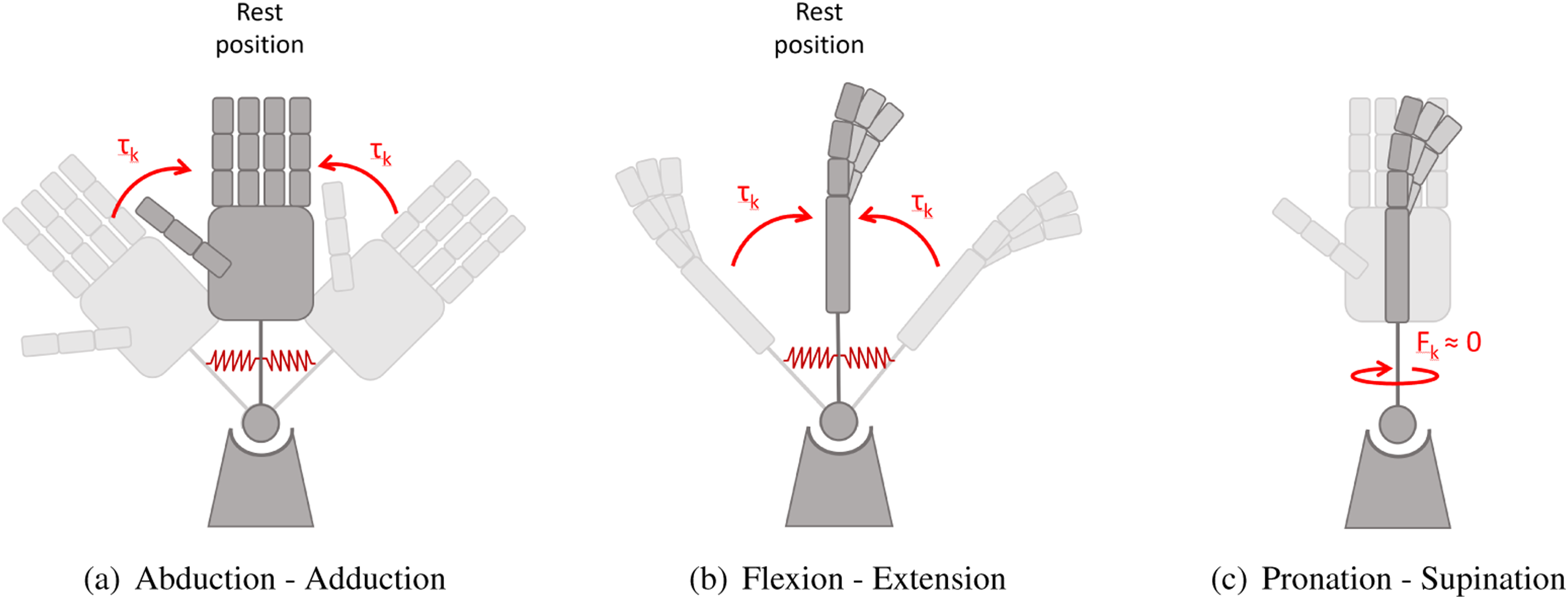
The mechanical response to F-E and A-A of the compliant flange
3.3. Control and electronics
A 12-bit resolution magnetic encoder (AS5045, AustriaMicrosystems) senses the cam disk rotation and feeds it to a custom electronic board (Della Santina et al., 2017). The board runs a PD (p = .03 and D = 0.2), with a current limit of 2000 mA, to regulate the cam disk rotation to an external reference value. The board is also in charge of reading two commercial sEMG sensors (13E200 = 60, OttobockGmbH, Germany), worn by the user to control the hand–wrist system. The board communicates (via USB serial port) to a PC running the external control loop described below in MATLAB Simulink (Mathworks, Inc).
We aim to evaluate the performance of the proposed wrist in combination with a prosthetic hand. Moreover, we want to compare its performance to that of the most common wrist used in the market, that is, a rotational prono/supination joint. Therefore, we use the same control strategy and hand prosthesis for both prosthetic solutions to highlight the differences only due to the mechanical capabilities of the wrist.
Control strategies adopted for multi-digit hands in the clinic (Cipriani et al., 2011; Dalley et al., 2009; Weir et al., 2008) and the market (Belter et al., 2013) were also used for hand–wrist combinations (Jiang et al. 2012, 2014; Piazza et al., 2020; Young et al., 2013). We adopt a control strategy commonly used in myoelectric prostheses consisting of a simple hand (1 DoA) and a rotational wrist (1 DoA). The strategy uses only two sEMG channels to control the direction of each DoA (wrist or hand). The choice between controlling the wrist or the hand depends on the velocity of the sEMG activation (e.g., four-channel control program [13E205 MyoRotronic, Ottobock]). As explained in the scheme in Figure 6(a), (a) slow activation sends the EMG proportionally commands to the hand velocity, while a fast activation goes to the wrist movement. The rationale behind this control modality being that fine grasping usually needs fine regulation of the hand position, therefore slowly increasing signals. Control method: (a) presents a scheme of the rationale behind the control methodology. Here, we generalize with a unique threshold for each DoA, but this might change depending on the muscle properties of the subject and the algorithm implementation. (b) shows the implemented Finite State Machine that commands both hand and wrist movements.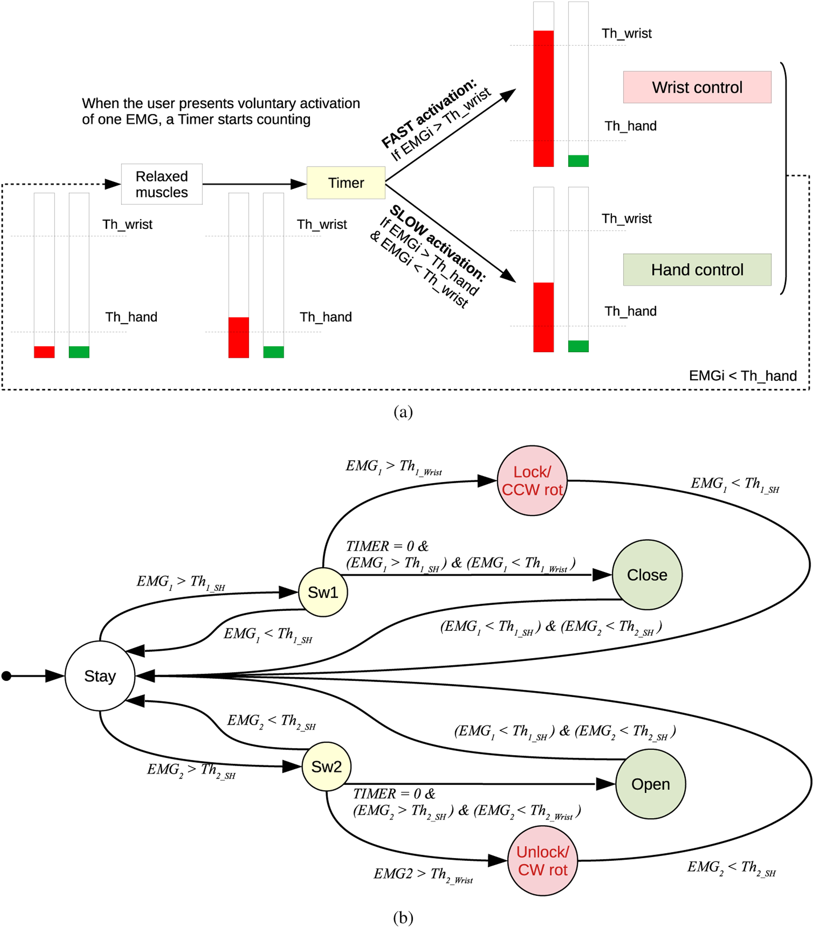
For the rotational prono/supination joint, the user controls the level of rotation, while for the proposed joint, a fast activation corresponds to the wrist locking. Figure 6(b) presents the Finite State Machine used. Although both robotic systems share the same control strategy, their different motion characteristics require a slightly different methodology to control each wrist. In the case of the rotational wrist, EMG i controls the rotation speed of the wrist pronation/supination angle. The user should remain in CW/CCWrot state until reaching the desired orientation. In our prototype, an EMG impulse higher than Th i locks the wrist in a certain orientation or unlocks it, depending on which EMG channel overcomes the threshold.
The states colored in red (Figure 6(b)) refer to wrist activations, and SH refers to the prosthetic hand used in the experiment. The Stay state maintains the position of each motor until the next change of state, while the two Sw i states execute a timer to evaluate the subject intention (to activate the wrist or the hand, depending on the threshold of activation). The threshold of the wrist Thi_wrist is larger than the hand one Thi_SH, implying that fast activations are related to the wrist.
4. Experimental validation
We tested the proposed system functionality (hereafter termed lockable wrist—LW) and compared its performance with a prono/supination joint (rotational wrist—RW) and a control wrist (CW) for each participant. For the comparison, we combined the two robotic wrists with the SoftHand Pro (SHP) prosthetic hand (Godfrey et al., 2018) using the control described in Sec. 3.3. Notably, also in the experiments with the control wrist, the able-bodied subjects used the SHP.
The experiment enrolled 10 participants: 9 able-bodied subjects (AB, 6 male and 3 female, 24–35 years old, 174.8±8.5 cm height) and 1 subject with a congenital malformation at the transradial level (left arm, female, 37 years old, 167 cm height). All of them gave their informed consent. Further details on the experimental setup, including the mechanical structure interfacing the different wrists and the prosthetic hand, are described later in Sec. 4.1.
To assess motor strategies used during movements, objective measures are necessary (de los Reyes-Guzmán et al., 2014). The reduction of compensatory motion of arm proximal joints is considered an objective measurement of the design success in new prosthetic devices (Metzger et al., 2012). Besides, the reduction of cognitive load or the intuitiveness required could be used for the same purpose. The latter is related to the timing, the willingness to use the additional feature, or may be evaluated through self-evaluation surveys from testers.
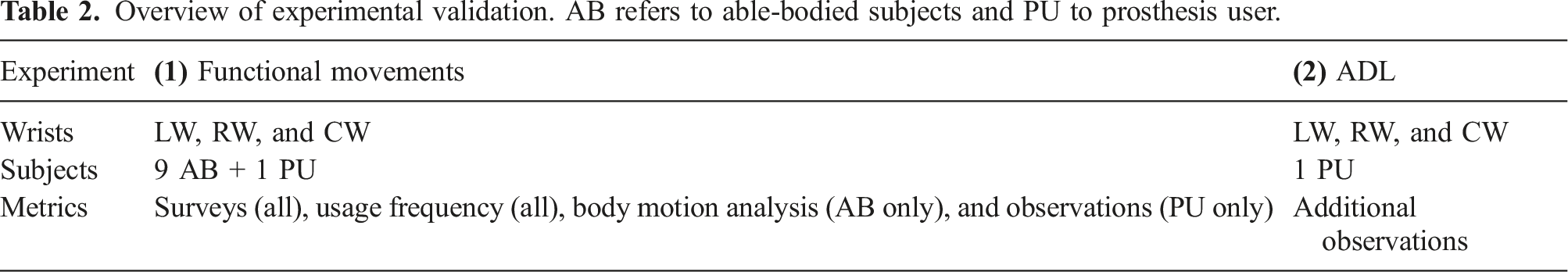
Overview of experimental validation. AB refers to able-bodied subjects and PU to prosthesis user.
By using the switchable impedance wrist, we hypothesize that the hand can be oriented in a position closer to an unimpaired arm during the pre-grasping phase and thereby improve system user-friendliness. Furthermore, its compliance could enhance a soft interaction with target objects and its partly adjustment for a more stable grip.
4.1. Materials
4.1.1. Robotic devices
Figure 7(a) and (b) show the robotic hardware used for the experiments by the able-bodied subjects and the prosthetic user, respectively. Both hardware setups use the same prosthetic hand (SHP) in all conditions to separate possible effects due to the impact of the robotic hand from those due to the wrist design.
The device in Figure 7(a) is a non-invasive bypass system composed of a hand, one of the two wrists (LW or RW), a handle, an armrest, and a mechanical interface to connect to a gravity compensation device. The gravity compensator prevents the total weight of the system from hindering myoelectric control. An external battery of 24V is located outside and powers both the wrist and hand (12V). For the RW case, we used a custom 1-DoF rotational wrist. We recorded position data from its encoder during task execution. For able-bodied subjects, the left arm was chosen as it was the subject’s non-dominant hand. This is considered appropriate as the majority of prosthesis users with a single loss use their prosthesis in a non-dominant manner, regardless of any natural dominance (Kyberd 2011). (a) Extra arm attached to the gravity compensator for able-bodied experiments and (b) prosthetic interface: EMG, socket, and wrist–hand system. Both cases show the interface adapted for the LW, but the same setup was recreated for the RW.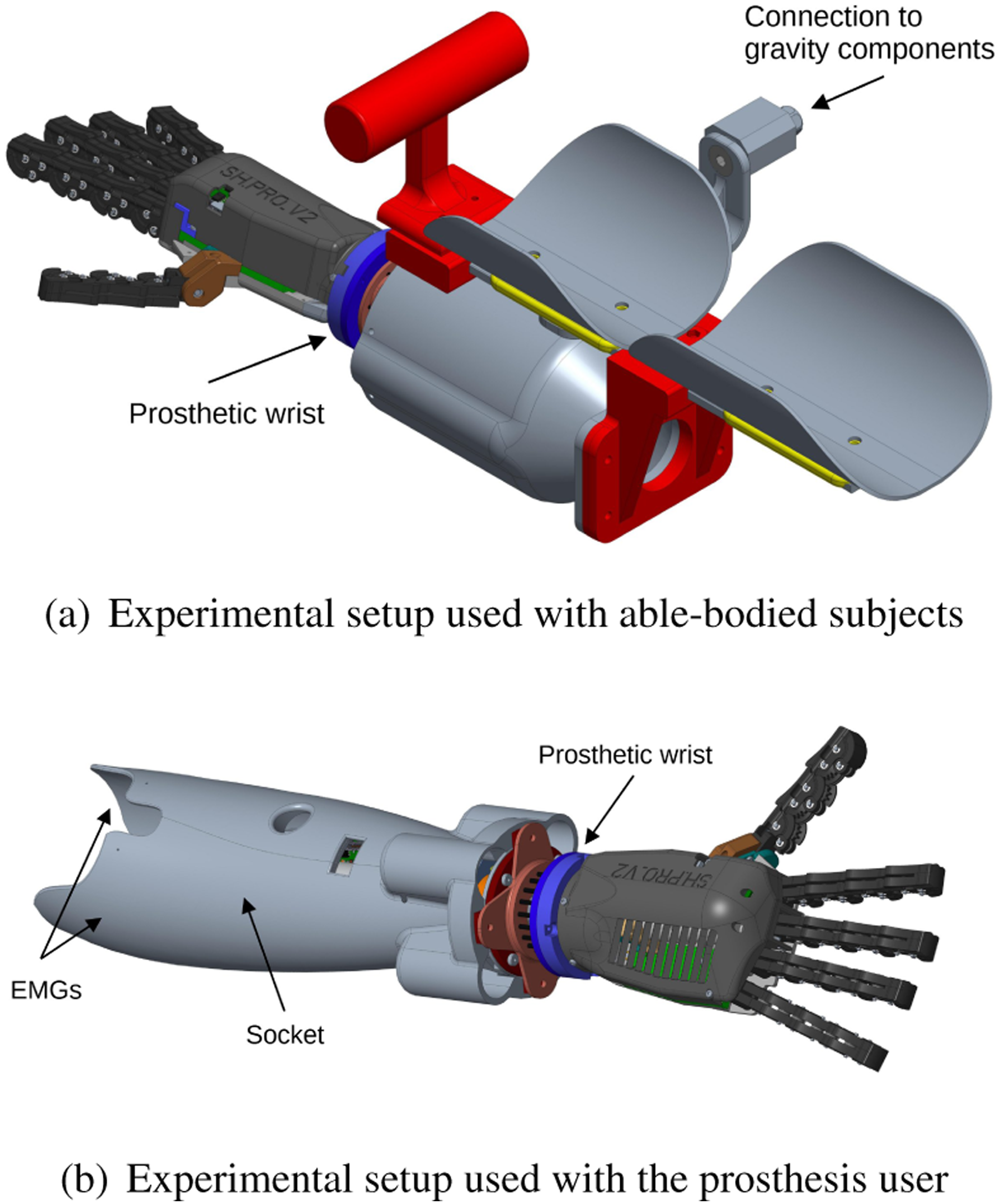
Figure 7(b) presents the socket embedding the lockable wrist that interfaces with the prosthesis user residual limb. Two customized sockets were manufactured to integrate one of the two robotic wrists (LW or RW). Both solutions include the corresponding wrist, its attachment with the SHP, and two sEMG sensors attached to a compliant inner socket that accommodates the stump of the prosthesis user. At the moment, the electronic board that controls the LW is located outside the socket and interfaced at the arm level with a fan to avoid high temperatures near the stump for security reasons. For the prosthesis user, we used the Electric Wrist Rotator from Ottobock as RW because of its compact design and well-known acceptance.
In the control test, able-bodied subjects used their wrist to orient the end effector with a handle interface that commanded the hand level of closure. In this case, we did not use EMG signals because only the myoelectric control of powered wrists is the scope of this paper. Accordingly, the gravity compensator is not present in this case, either in the prosthesis user’s experiments (PU). The prosthesis user unimpaired arm (right) performed the experiment for the control test.
4.1.2. Measuring instruments
In experiment Sketch of the general setup of the experiment together with the object dimensions. On the left side, a picture of an able-bodied subject during the experiment. The right side presents an initial configuration of objects (1. Grasp). The final configuration (2. release) is reported with lighter colors.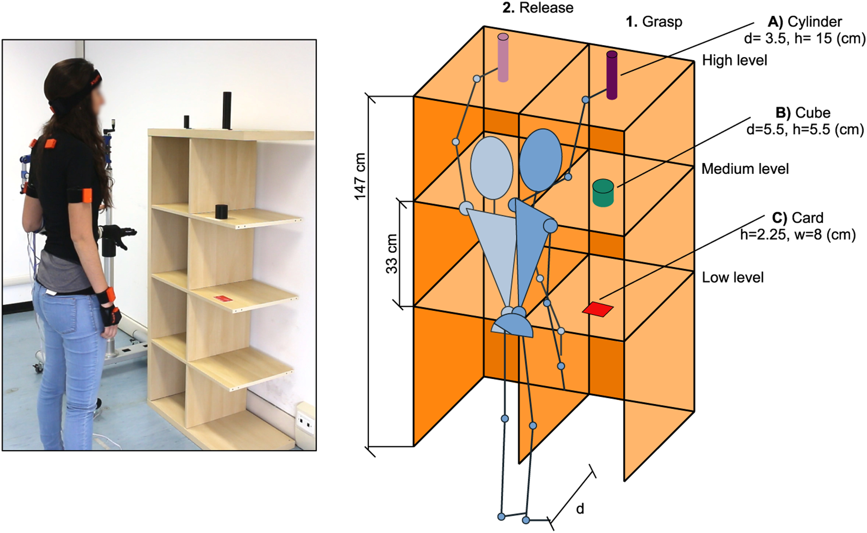
Unfortunately, the electromagnetic interference from the actuators in the device of Figure 7(b) interferes with the Xsens calibration. The primary reason for the interference was the presence of the bypass interface. While all Xsens sensors could be placed directly on the skin of able-bodied participants, even when they used the bypass to hold the robotic system, prosthesis users had to position the sensors on their forearm and hand in proximity to the robotic system. This configuration led to electronic interference between the sensors and the robotic system during calibration and subsequent use. Despite various attempts to shield the electronics from sensor placement, it proved insufficient for reliable operation. Consequently, we decided against using Xsens with prosthesis users and instead utilized its data and experience as a qualitative complement of our study.
In experiment
4.1.3. Specimens
In experiment
Figure 8 shows a picture and a sketch of the shelf used, a standard IKEA KALLAX shelf. It has six slots on three different height levels used and two sides (left and right). As shown in Figure 8, a piece of paper-tape marks the position, on each of the three right shelves, where objects are initially placed. Objects must be released at the same height in the left side (no specific location).
All participants were positioned in front of the shelf at a fixed distance d. Nonetheless, due to the inevitable differences in the height among subjects, the distance of each shelf level relative to the subject varies on every occasion. After the completion of each grasping condition, subjects were instructed to return to the starting body position.
In experiment
4.2. Methods
4.2.1. Experimental protocol
Protocol steps and expected duration.
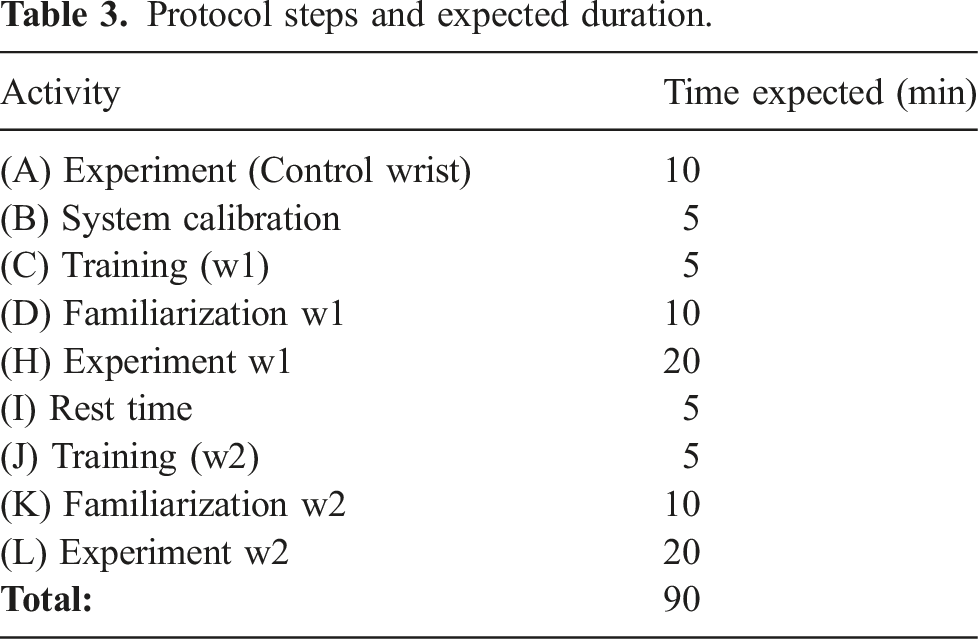
Due to the difficulties of learning a more complex myoelectric control strategy, before starting with the experimental protocol, the PU tried and got familiar with the control strategy with no robotic system attached to her stump. Because of the difficulties of donning/doffing the system, we randomized only the order of the grasping conditions and the PU executed the protocol in the following order: the intact arm (CW) followed by the rotational one (RW) and finally, the lockable wrist (LW). We decided this order because, in case of fatigue, the results should affect the proposed system instead of deteriorating the PU experience with the commercial system.
The experiment
The experiment
4.2.2. Performance metrics
Regarding the collected data from experiment
5. Results
This section presents the results from the functional movements test
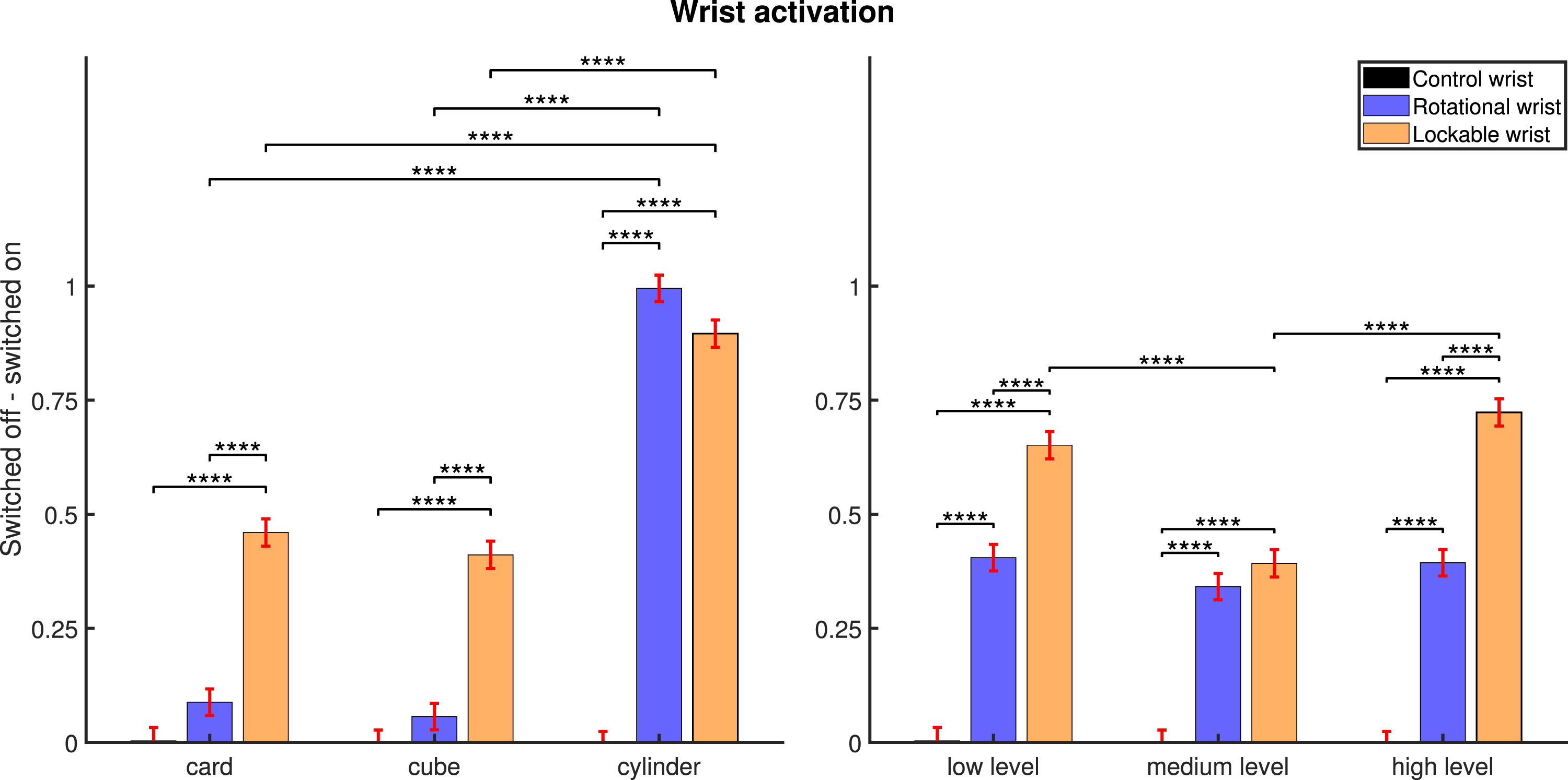
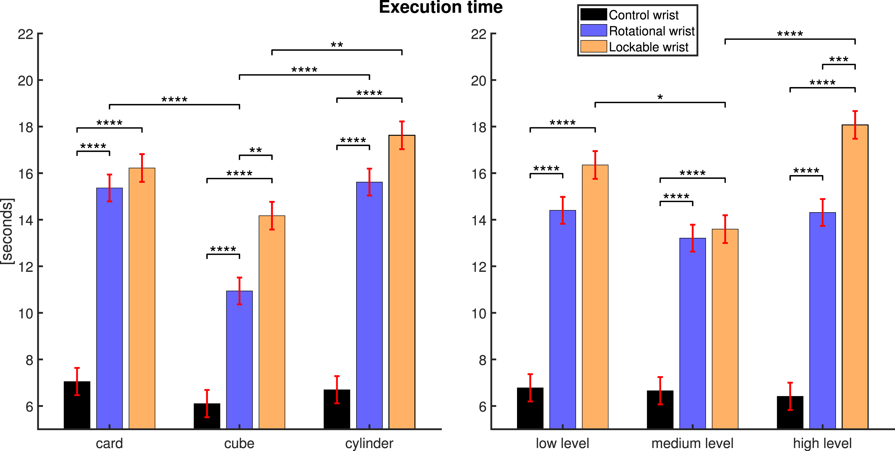
We report Figure 9 to evaluate the impact of each wrist on functional movements through the average activation rate of each wrist during task performance (Figure 9(a)) and the average execution time (Figure 9(b)). Moreover, we also report the average task execution time limiting to the sole cases when wrists are activated (Figure 9(c)), to factor out the non-negligible activation time from the analysis. The main distinction between both time metrics lies in the analysis perspective. The general average execution time (termed Execution time) considers task completion, which may or may not involve active use of a robotic system. In contrast, the second metric (termed Prosthetic aids in use) focuses specifically on trials when the robotic system is actively engaged. This allows us to assess how the use of the robotic system impacts the execution time, particularly when the LW is used for configuration or stiffness switch, and when the RW is utilized for hand rotation. Activation and execution time for all able-bodied subjects (n = 9). The black-dashed line divides the graph between the control wrist and the results with the prosthetic aids. The clear gray bar highlights the prosthetic wrist with better results for each aspect. Tukey–Kramer test significance is detailed with asterisks in the upper part of each graph. The estimated means for each wrist of study are presented with a bar plot, and the error bar refers to their standard error.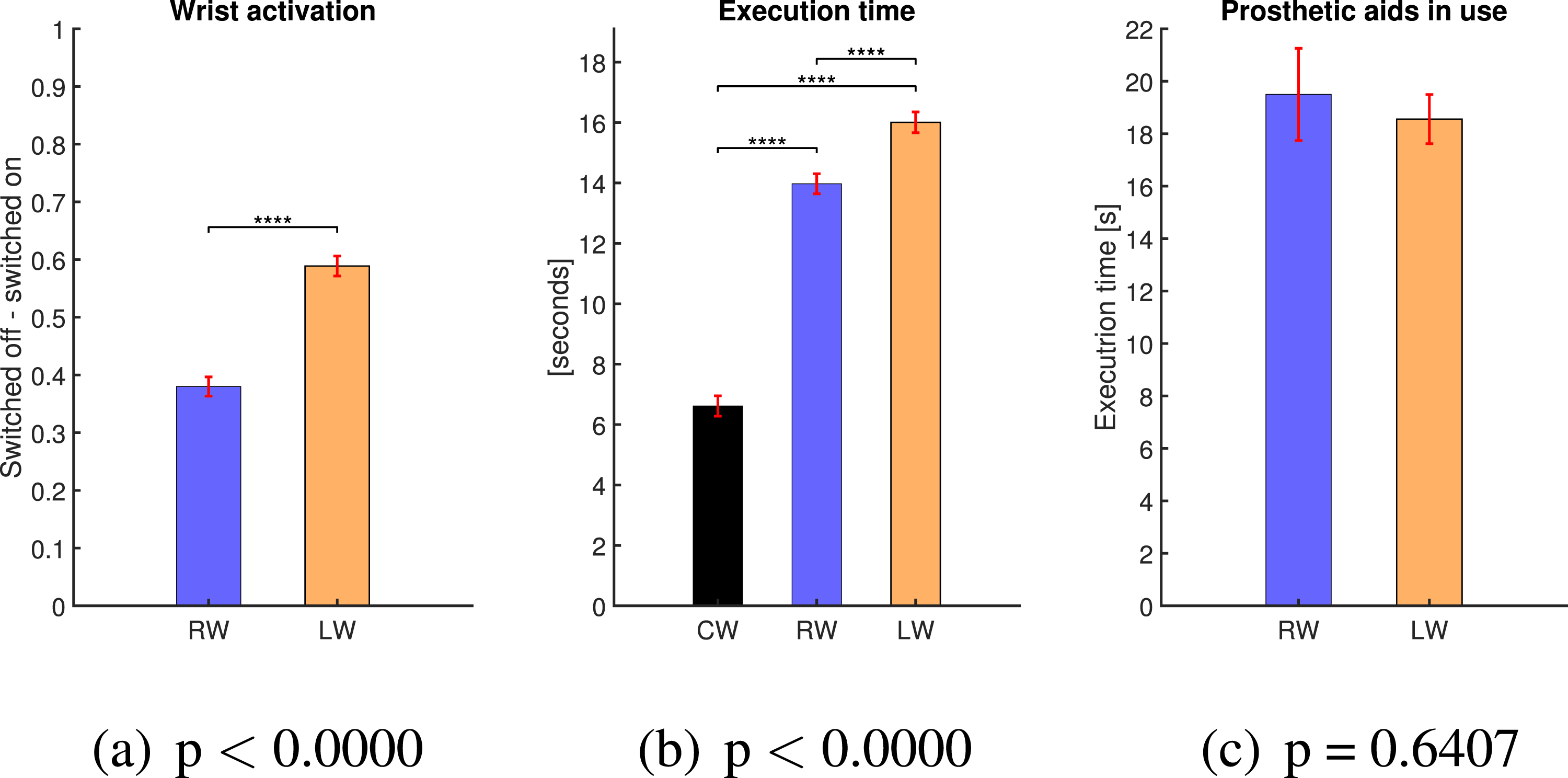
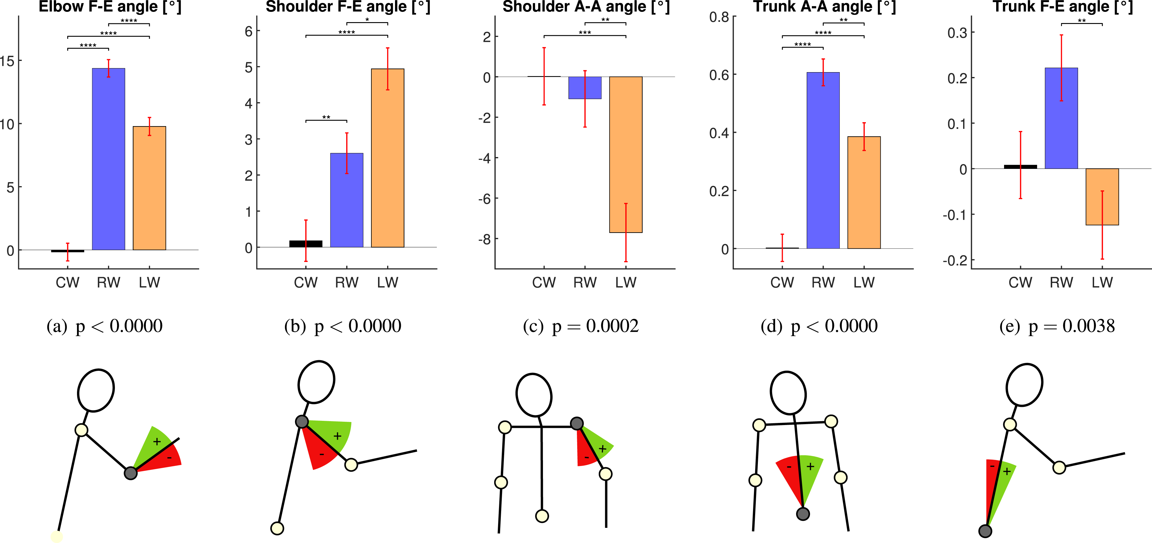
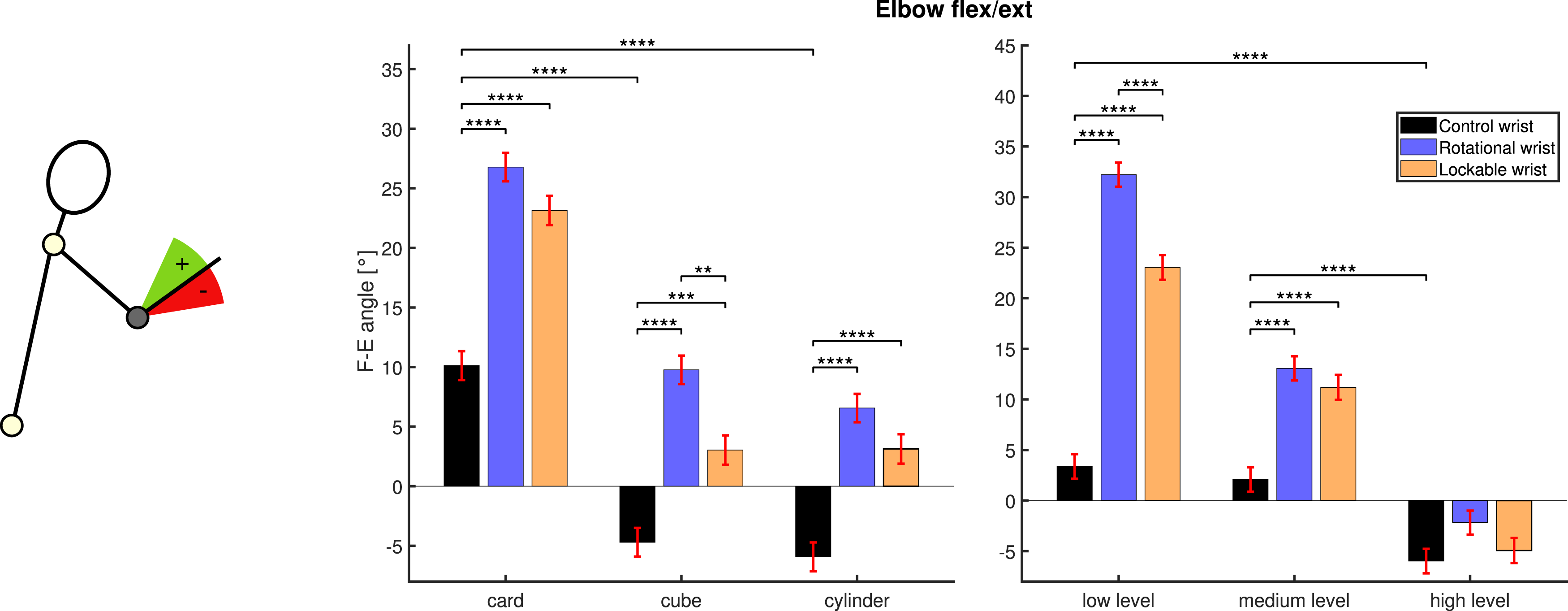
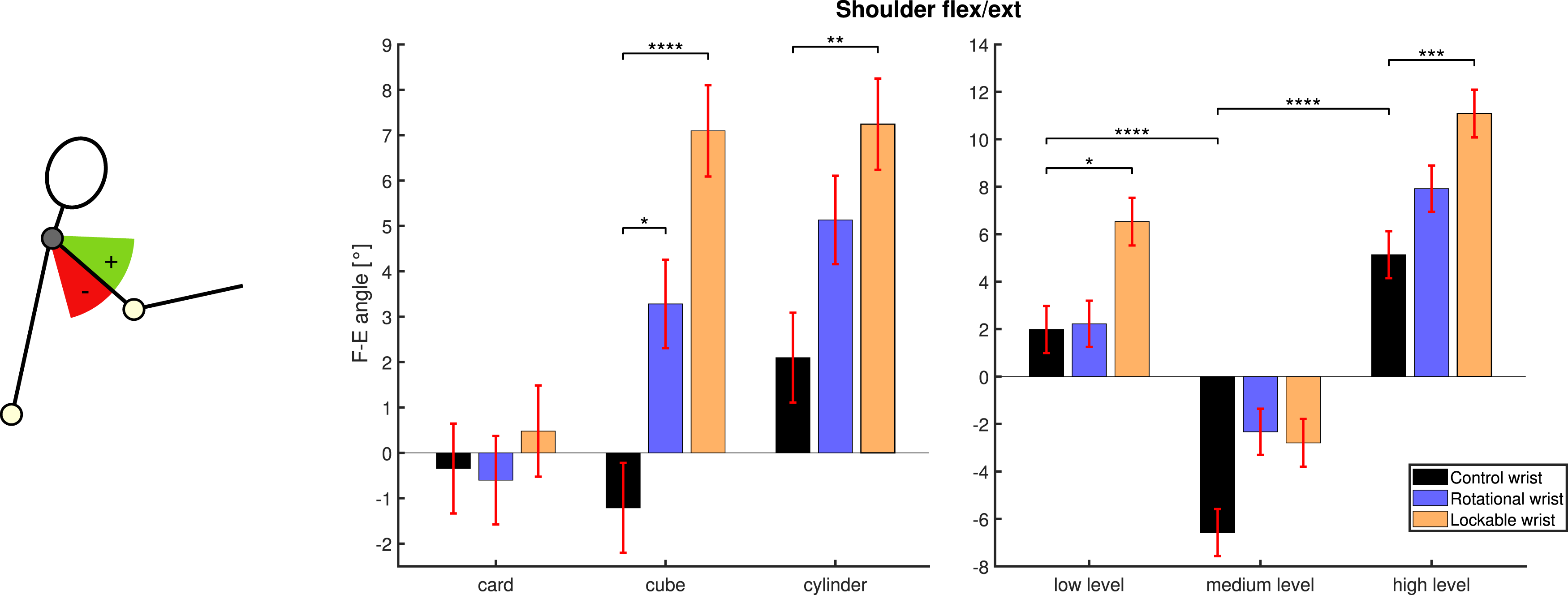
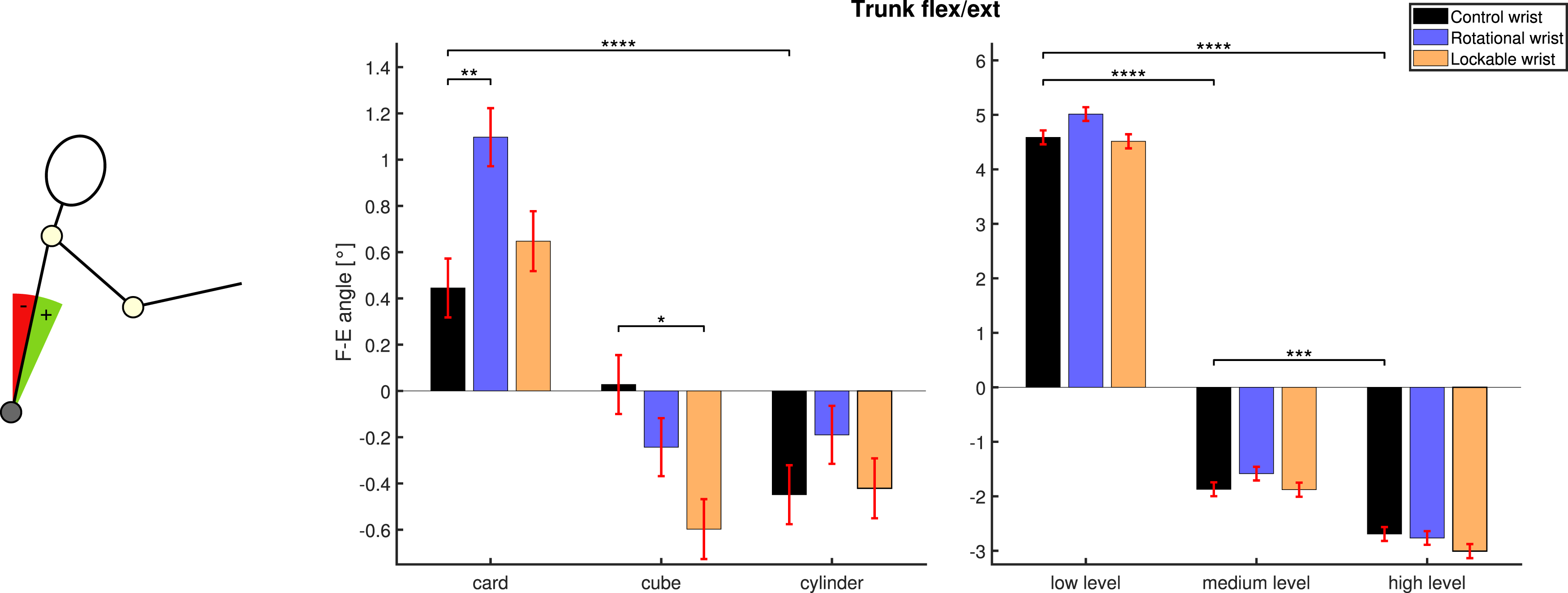
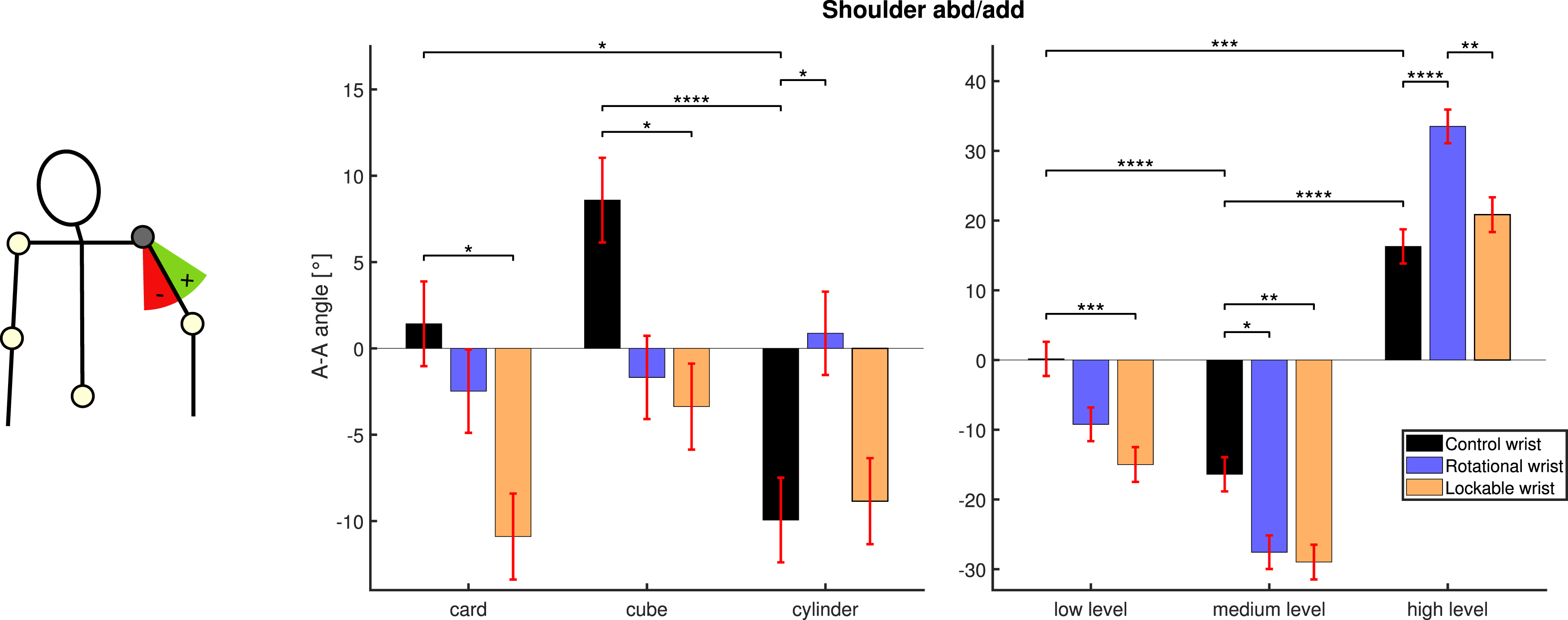
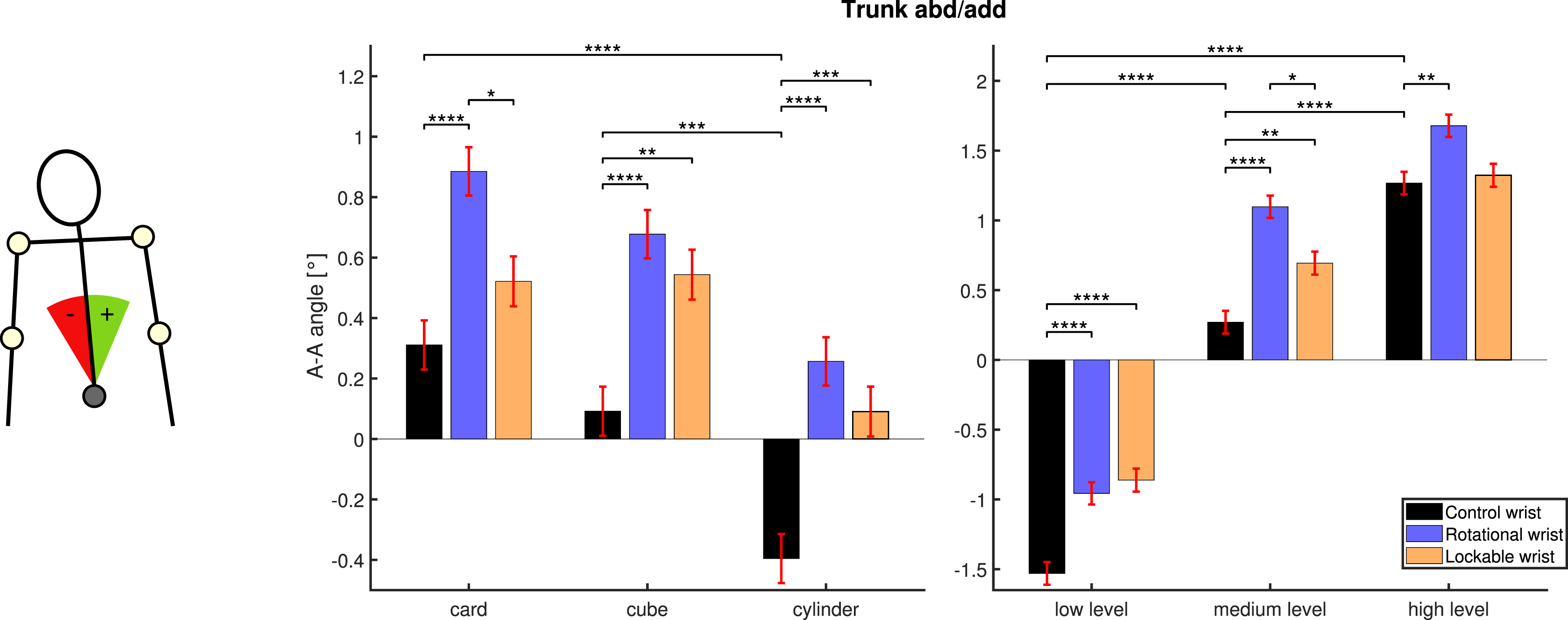
We analyze Figures 10 and 11 to evaluate the impact of each wrist on functional movements through the compensatory motions of five body segment angles: Elbow flexion-extension, Shoulder flexion-extension, Shoulder adduction-abduction, Trunk adduction-abduction, and Trunk flexion-extension. For those angles, Figure 10 reports the average values for each subject during the experiments (considering all trials). By subtracting an intra-subject average value (considering only trails with the control wrist), we define the compensatory movement angles (compensatory movements, for short), that we report in Figure 11. Moreover, for each of the previous figures, we report interaction analyses correlating activation rates, average execution times, and compensatory angles to the shape of the objects and their positions on the shelf (reported in Figures 12–18). Subjects’ means for each compensatory angle studied. The estimated mean for each subject is represented with a bar, together with its standard error. The average value is detailed in the background in a lighter color. Compensatory movements from 5 body angles—subject’s joint mean is removed to wrists comparable among subjects. A horizontal line in panels (a–e) indicates the neutral posture, which refers to each subject’s average angle. A schematic body representation establishes the direction of compensatory movements with respect to each subject’s average angle (neutral posture). The estimated means for each wrist of study are presented with a bar plot, and the error bar refers to their standard error. CW (control wrist) is the natural wrist of the subject. RW refers to rotational wrist and LW to the lockable wrist. We assume a robotic wrist obtains better results when performing less compensatory movements—giving the possibility to perform the task with a smaller workspace. The p-value from N-Way ANOVA is detailed in the caption. Significance from Tukey–Kramer—hsd post hoc test—is detailed with asterisks in the upper part of each graph. Interaction test for wrist activation. On the left side, there is the object-dependent wrist activation, while on the right side, results depend on the height. The left side shows the effect depending on the object: p Interaction tests for execution time. The left side shows the results depending on the object: p = .0028 and the right side, depending on the height: p = .0019 (interaction p-value from N-Way ANOVA). Significance from Tukey–Kramer—hsd post hoc test—is detailed with asterisks in the upper part. The estimated means are presented with a bar plot, and the error bar refers to their standard error. Interaction tests for elbow flex/ext. angle. The left side shows the effect depending on the object: p = .1375 and the right side, depending on the height: p Interaction tests for shoulder flex/ext. angle. The left side shows the results depending on the object: p = .0051 and the right side, depending on the height: p = .0972 (interaction p-value from N-Way ANOVA). Significance from Tukey–Kramer—hsd post hoc test—is detailed with asterisks in the upper part. The estimated means are presented with a bar plot, and the error bar refers to their standard error. Interaction tests for trunk flex/ext. angle. The left side shows the results depending on the object: p = .0019 and the right side, depending on the height: p = .3271 (interaction p-value from N-Way ANOVA). Significance from Tukey–Kramer—hsd post hoc test—is detailed with asterisks in the upper part. The estimated means are presented with a bar plot, and the error bar refers to their standard error. Interaction tests for shoulder abd/add. angle. The left side shows the results depending on the object: p = .0003 and the right side, depending on the wrist and height: p Interaction tests for trunk abd/add. angle. The left side shows the effect depending on the object: p = .4052 and the right side, depending on the height: p = .0003 (interaction p-value from N-Way ANOVA). Significance from Tukey–Kramer—hsd post hoc test—is detailed with asterisks in the upper part. The estimated means are presented with a bar plot, and the error bar refers to their standard error.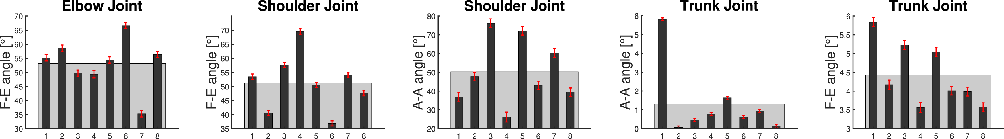
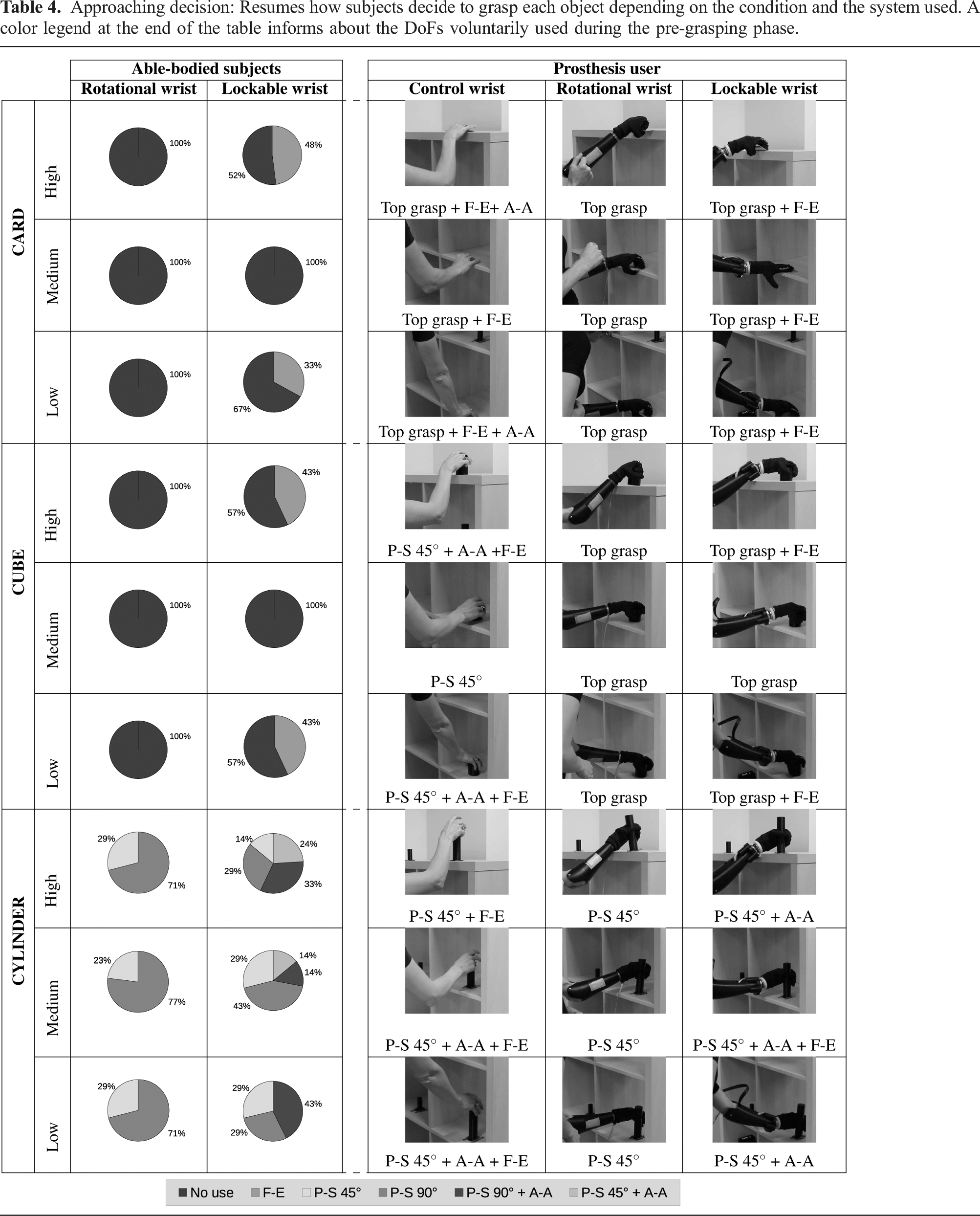
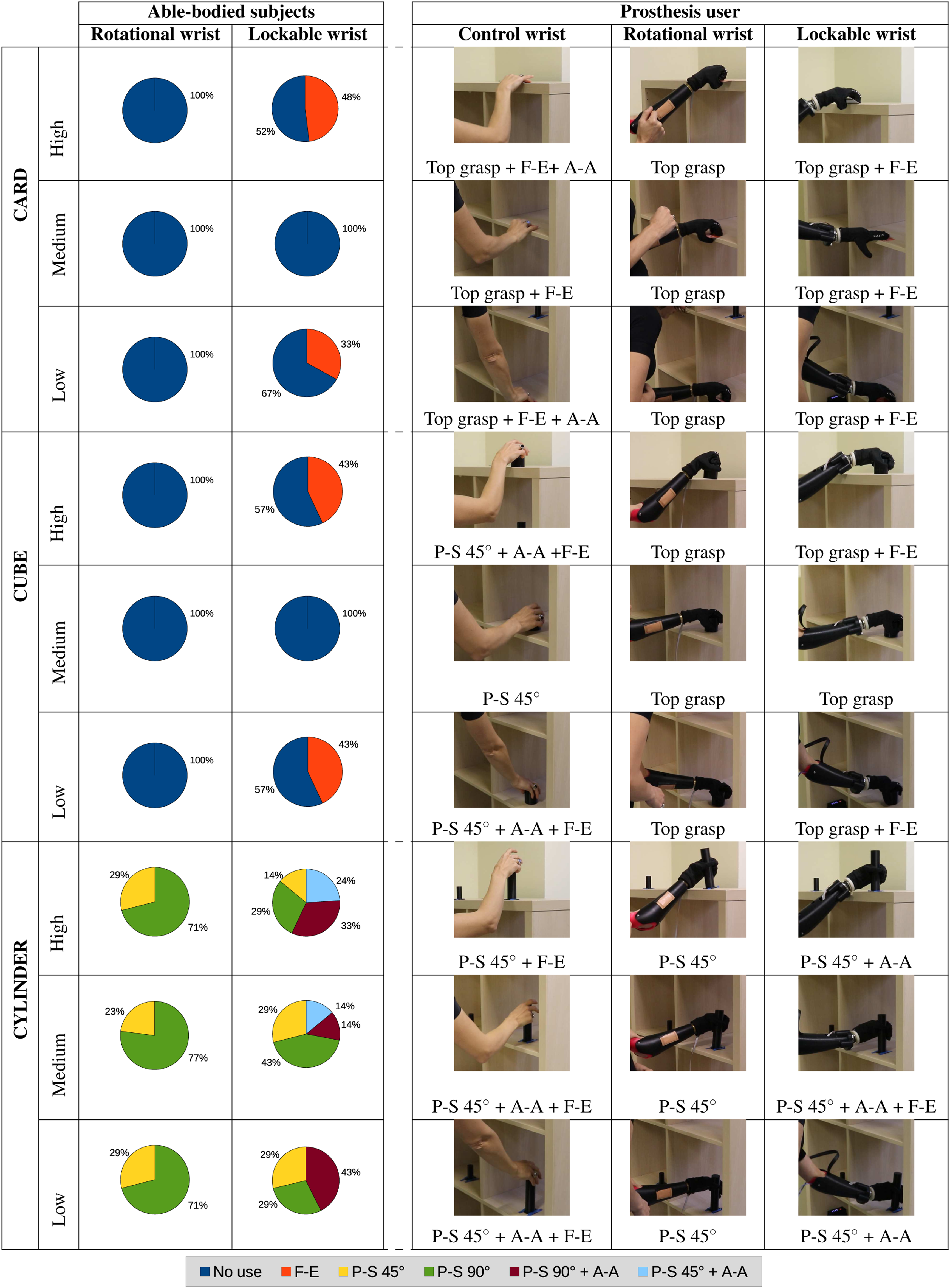
Approaching decision: Resumes how subjects decide to grasp each object depending on the condition and the system used. A color legend at the end of the table informs about the DoFs voluntarily used during the pre-grasping phase.
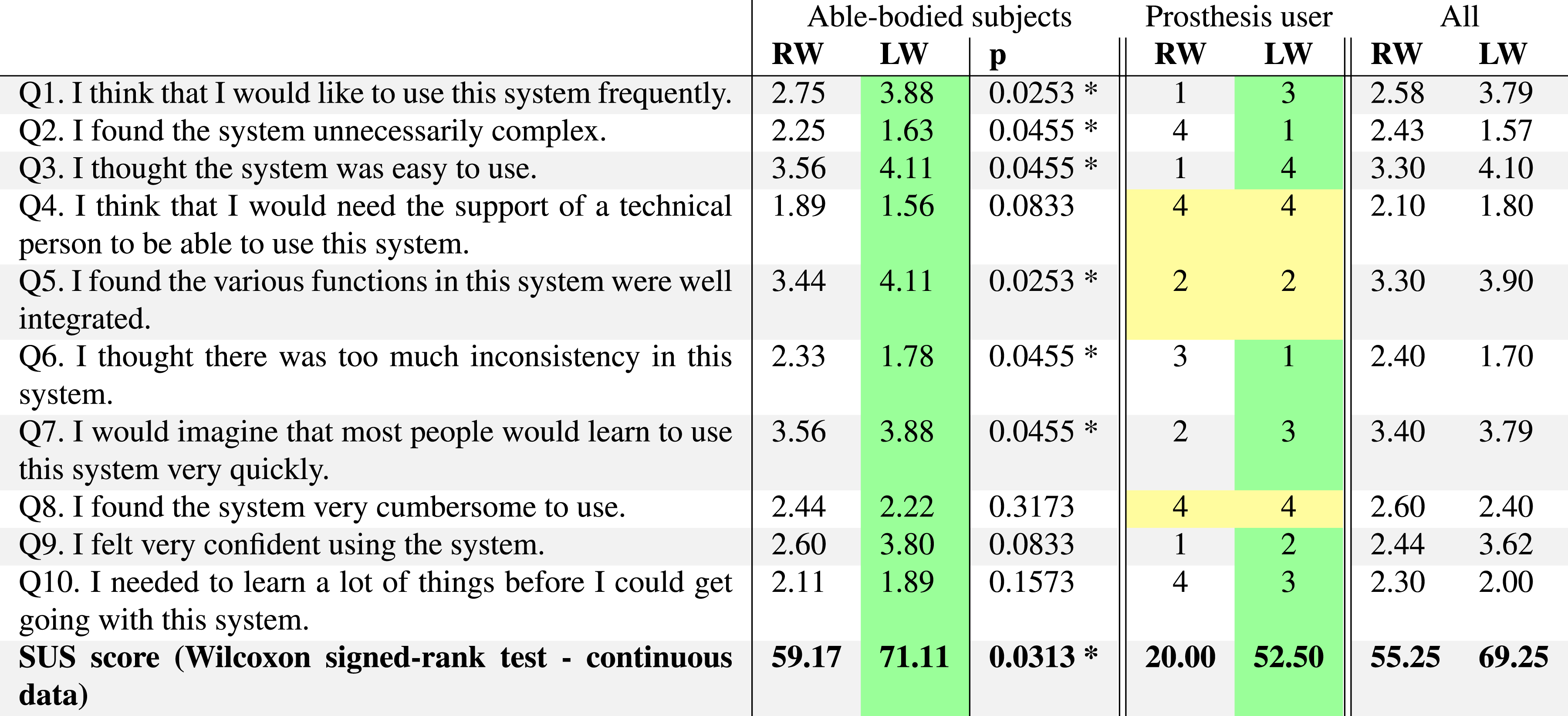
System usability scale (SUS). Cells in green highlight answers with better score, while the yellow ones represent an equal result between prostheses.

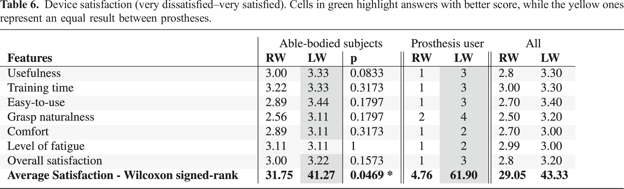
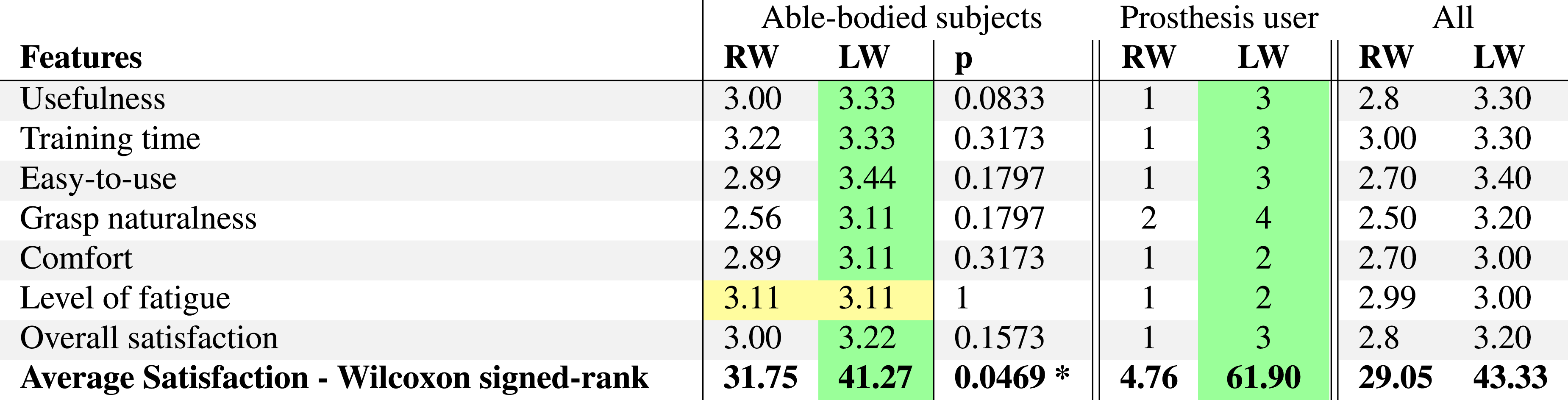
Device satisfaction (very dissatisfied–very satisfied). Cells in green highlight answers with better score, while the yellow ones represent an equal result between prostheses.
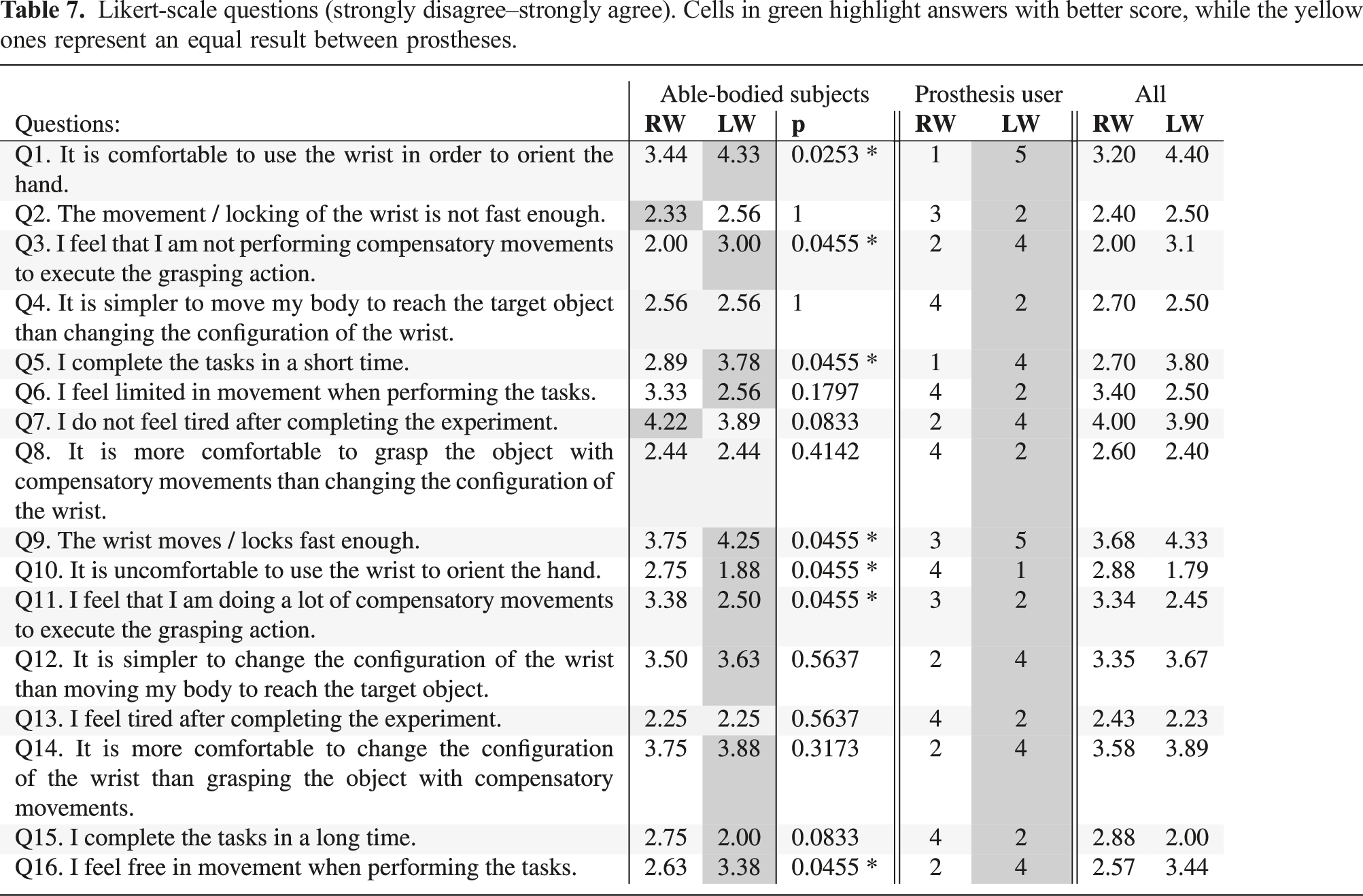
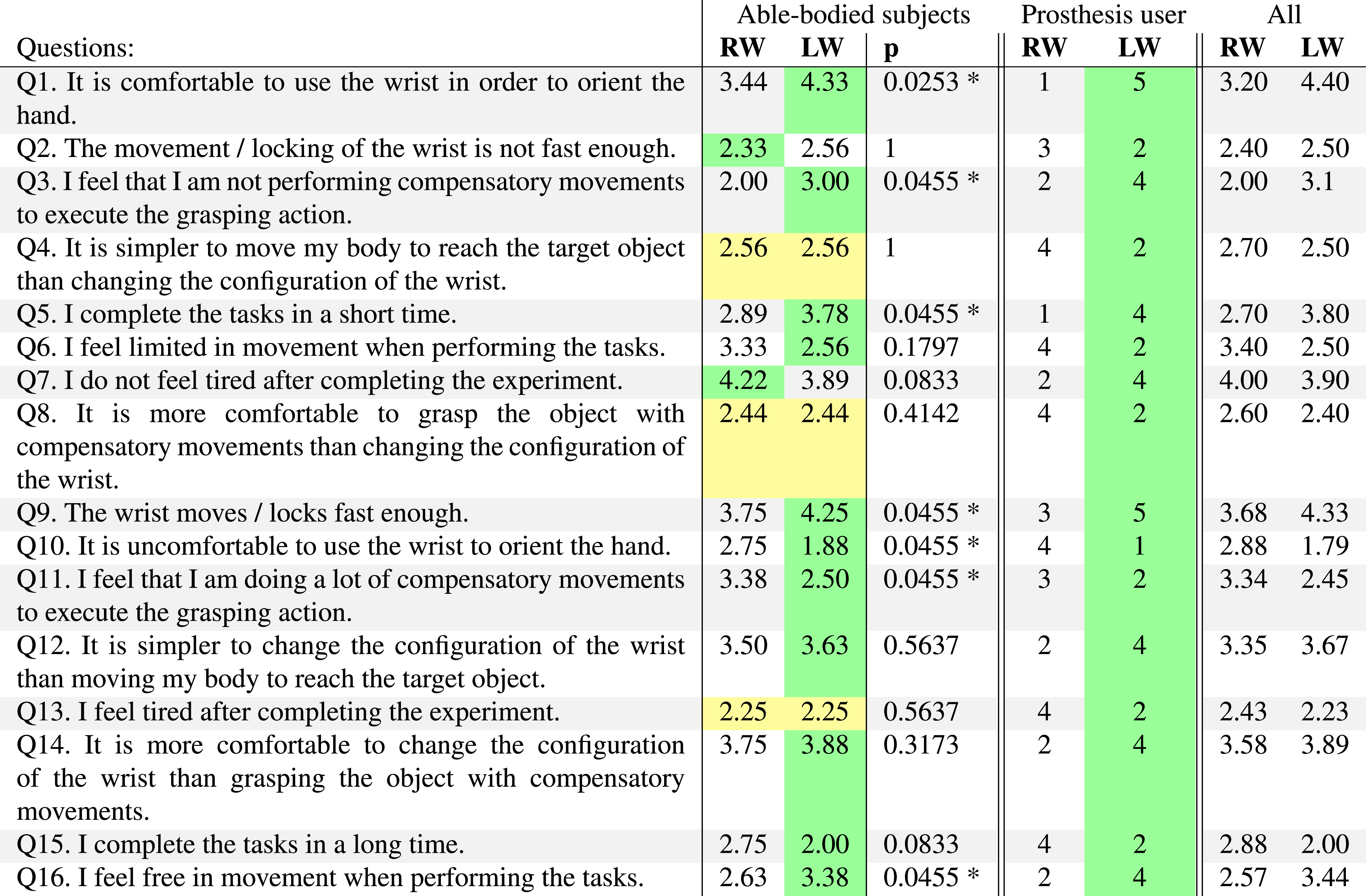
Likert-scale questions (strongly disagree–strongly agree). Cells in green highlight answers with better score, while the yellow ones represent an equal result between prostheses.
All data are processed, visualized, and statistically analyzed with MATLAB. Data are reported for each wrist type by indicating the initial letters: LW (Lockable wrist), RW (Rotational wrist), and CW (Control wrist). To reduce inter-subject variations, the two powered wrists are compared to each subject CW case. Results report the estimated means after an N-way ANOVA test, unless another test is explicitly mentioned, and represented in a bar plot, where the error bars refer to their standard error. The p-values are detailed in the caption of the corresponding figures. Significance from a Tukey–Kramer, also known as hsd post hoc test, is detailed through asterisks between compared couples when significant.
5.1. Able-bodied subjects
5.1.1. Functional movements
The activation rate and execution time for all able-bodied subjects (n = 9) are presented in Figure 9.
We observe that the LW presents a larger activation rate (+20%) than the RW, showing the interest of the participants in using the proposed system (Figure 9(a)). Activating either of the two wrists, the user positions the prosthetic hand for (a more comfortable) grasping action, which affects the total execution time. Indeed, the RW performed 2s faster than the LW (Figure 9(b)). Nonetheless, we observe no significant differences in execution time (p = .6407) if averaging only across those cases when both prosthetic aids were used actively (Figure 9(c)). That suggests that the observed 2s difference does not come from the LW performing worse time-wise.
Figure 10 reports the average values of the five body angles analyzed for compensatory motions. The conspicuous inter-subject differences confirm the heavy dependence of the final body configuration on the subject’s physical features and personal preferences. Therefore, we define compensatory movement angles by subtraction, joint by joint, from the average angle of each subject across trials performed only with the control wrist. Note that even when using the control wrist, participants wear a bypass to execute the tasks with the same end-effector, which may influence the naturalness of their grasping body posture. For this reason, the method previously described assumes that the body postures for the control wrist are relatively more natural than the robotic wrists but not necessarily ideal. The resulting data (see, e.g., Figure 11) highlights the effects of each wrist in a more comparable way across subjects. Deviations from this intra-subject average posture were quantified as body compensations. Larger deviations indicate greater limitations imposed by the prosthetic device (or bypass), resulting in a less comfortable posture and, therefore, a worst wrist function. This approach was chosen due to the diverse configurations of the prosthetic devices respect to the control wrist case, variability among subjects’ choices, and the need for a standardized reference point. Figure 11 proves that the LW obtains significantly smaller values than the RW for all angles except for the Shoulder joint. Note that, to get a more straighten arm, desired for a reaching phase, we expect smaller Elbow F-E and bigger Shoulder F-E angles. This combination occurs for the LW. Furthermore, a more negative Shoulder A-A angle indicates a more proximal location of the arm, also desired for comfort.
We report the analysis of the interaction between wrist types and grasped objects, and between wrist types and height levels. Although we show graphs from all measurements, we only discuss observations concerning those tests that obtained a significant p-value at an N-Way ANOVA, indicating significant differences among groups of the corresponding factor.
In the context of this study, robotic wrists interface with able-bodied participants via a bypass below the arm, which connects to the gravity compensation device. This interface configuration can potentially influence trajectory decisions when compared to scenarios involving prosthesis users, where wrist interfaces directly at the socket level. While one might expect able-bodied subjects to perform control actions comfortably, note that our approach considers the average joint angles across various tasks using only the control wrist, each task involving multiple objects and differing shelf levels. This approach allows us to assess the relative comfort levels associated with specific wrist configurations, including for the control wrist. For instance, we can discern that grasping objects on higher shelves or handling cylindrical objects may necessitate more body compensation than tasks involving simpler objects such as a box at mid-level shelves. By using this metric, we can effectively compare body compensations both within and across different wrist solutions.
Figure 12 shows the interaction tests for wrist activation rates. On the left side, we observe that participants use the LW significantly more often than the RW when grasping the card and cube, while in the case of the cylinder, both devices are actively used, at least for prono/supination movements. On the right side, results show that LW is used significantly more often than RW at the low and high level, that is, at the extreme conditions. Note also that there is no intra-RW difference corresponding to heights, while the LW presents a clear difference in usage at the medium level.
Figure 13 shows interaction tests about the task execution time. The first observations that we report are that the CW is significantly different from both prosthetic aids and that there are no differences among the diverse CW cases, that is, no intra-CW differences. Moreover, on the left side of Figure 13, we see that although the LW is slower than the RW for all objects, we find a significant difference only for the cube, suggesting the inconvenience in the active use of the LW to modify the wrist configuration only for this object. Note that RW and LW perform similarly for the card. However, while the LW is used in 50% of the occasions (see the left side of Figure 12), the RW is not intentionally used for this object. That suggests that LW improves the grasping of flat objects so much to recover the loss due to the time spent activating and orienting the wrist. Regarding height-dependent results, on the right side of Figure 13, even though generally LW
Figures 14–18 report the interaction tests concerning the five body angles studied to evaluate the reduction of compensatory movements with respect to the same two factors: object shape and height level. First, we present three angles that move in the sagittal plane. In the elbow flex/ext. angle, the right side of Figure 14 shows that there is consistency among wrist types, increasing the difference between CW and the robotic aids the lower is the height level. Although generally LW
In regards to the frontal plane, results from the shoulder abd/add. angle are influenced by both the object and the height level (see Figure 17). No statistical object-dependent difference between robotic aids occurs, even though the LW presents “better” results (i.e., closer to a stand straight up position and the arm more proximal to the trunk) in all conditions. For the cube, where the LW is not actively used, the difference between robotic solutions is very small. Instead, in the cylinder, the LW is similar to CW, while the RW is significantly higher than CW. There is an intra-CW statistical difference among height levels, which validates the existence of diverse requirements from the experimental protocol affecting this angle. Shoulder abd/add. angle is largely affected at the high level (with positive values respect to the intra-subject average), where LW is significantly lower than RW. There, the LW resulted in a much closer position to the natural one, that is, CW presents significant difference only with RW. Results from the trunk abd/add. angle are influenced only from the height level with significance between robotic aids at the medium level and with LW
Finally, the wrist configurations used for each experimental condition are observed and reported in Table 4, in terms of the desired approach directions and DoFs used. The first two columns report the usage percentage of each prosthetic wrist for able-bodied subjects after the visual inspection of the video footage. We observe that able-bodied subjects used the RW only to grasp the cylinder, regardless of the height. Participants performed grasps in two types of configurations for the RW, related only to the P-S; lateral grasp at 90°, or lateral grasp at 45°. On the contrary, the LW was used for all objects at certain height conditions. The LW was not intentionally used only for the card and cube at the medium level. Some participants used F-E motion to improve the grasp of these objects in extreme cases, that is, low and high heights. This use could depend on the height of the subject and users’ expertise in controlling the device. In the case of the cylinder, the LW was used in 100% of the cases with different approaches. P-S motion was used to modify hand configuration at 45° or 90°, similar to the ones used for the RW. Besides, some participants explored a combination of P-S with A-A to facilitate the grasp depending on the height level. The percentage of combined approaches is lower in the medium level with 30%. Instead, in the high level, subjects profited more from combinations of P-S and A-A with its choice in more than 50% of the occasions.
5.1.2. Self-evaluation
We measure subjects’ experiences through three different questionnaires. The average responses from able-bodied subjects, together with the p-value from the chi-square statistic, are used to prove statistical significance between prosthetic wrists after a Friedman’s test (dependent categorical variables) applied to each question included: the System Usability Scale (Table 5), a device satisfaction rank (Table 6), and 16 custom questions (Table 7). Moreover, Table 5 presents the average System Usability Scale (SUS) scores from all participants. Likewise, the average percentage of total satisfaction can be seen in the last row of Table 6, which considers the 7 features included in the table. Note that Table 7 does not report a standard survey or equivalent, where a total or average score would be applicable. Due to the dependency and continuity of these two average scores, we performed a Wilcoxon signed-rank test to compare results. Their corresponding p-value is also reported.
Considering all questions included in the self-evaluation, there is a general tendency towards preferring the proposed friction-lockable wrist (LW) over the conventional rotational one (RW). Subjects assigned a higher score to the LW in 82% of the occasions. Only in 6% of the questions, the RW had got more favorable results, while participants considered the performance of both wrists equally useful in 12% of the questions.
Results in Table 5 prove that the LW obtained an SUS score above the average in the literature (i.e., 68), while the average score for the RW is 59.17. The difference between them resulted statistically significant, with a preference for LW. Furthermore, we observed a significant preference of LW over RW in SUS questions (Table 5) regarding control intuitiveness (Q2, Q3, and Q7) and a good integration (Q1, Q5, and Q6).
Previous results are also supported by the outcomes of the device satisfaction, presented in Table 6. The difference in the percentage of the total satisfaction resulted also statistically significant, with a higher value for LW, suggesting a higher degree of acceptability for the proposed system.
In Table 7, questions regarding the perception of a decrease in compensatory movements (Q3, Q11, and Q16), questions concerning the comfortability when performing functional tasks (Q1 and Q10), and questions about the perception of time spent to modify the end-effector configuration (Q5 and Q9), all obtained a significant improvement. Overall, it is possible to observe a significant difference between prosthetic solutions in 43% of the questions. Results highlight a preference for LW in all cases.
5.2. Subject with limb loss
Even though the results were encouraging from able-bodied subjects, we present additional results from one subject with limb loss for a more direct application and to observe correlation with the previous.
5.2.1. Functional movements
Table 4 shows the wrist usage also for the prosthesis user. The last three columns show, through a picture, the desired approach. Moreover, we report the combination of the DoFs used to orient the end-effector, although it is only qualitative data. Concerning the intact hand (CW), we observed the use of a DoF or a combination of DoFs impossible to reproduce with the RW on 100% of occasions. That highlights the limitations of this commercial solution to recreate natural grasps because of poor functionality. In 88.88% of the cases, the proposed solution (LW) achieves a configuration unreachable by RW. Both prosthetic aids exploit the same approach only for the cube at the middle level, which appears to be probably the easiest grasping condition.
5.2.2. Self-evaluation
The prosthesis user answered the same surveys to evaluate these perceptions from a real user point of view. Tables 5, 6, and 7 report the prosthesis user’s score to each question. In agreement with able-bodied subjects’ results, the prosthesis user prefers the proposed system (LW) in all features except for 3 questions of the SUS scale. Considering all 33 questions included in the surveys, the prosthesis user preferred the LW over the RW in 91% of the questions and showed no difference in 9%. We observed a large discrepancy (i.e., 3/4 point difference) in questions regarding easy-to-use (Q2 and Q3 from Table 5), and LW achieved a higher SUS score (52.50) than RW (20.00). While the average device satisfaction (Table 6) for the RW is in the range of very dissatisfied (4.76), the LW was evaluated in the range of satisfied (61.90), with the maximum punctuation given to grasp naturalness. Table 7 shows a large discordance between prostheses for Q1, Q5, and Q10, which refer to comfortability.
6. Discussion
6.1. Able-bodied subjects
As shown in Figure 9(c), there is no significant difference when both prostheses are active. This suggests that, even if the general execution time favors the RW (Figure 9(a)), the wrist was not actively used during the test (
Figure 19 shows a sequence of pictures from an able-bodied subject to qualitatively compare grasp naturalness. Underlining the difficulties encountered in extreme cases, where objects shape or their position can hinder the grasp success or require unnatural body configurations, pictures show similarities between the CW and the proposed alternative (LW). Five angles are considered to study body compensations and to present quantitative data regarding this common problem in prosthetics. Among them, we noticed that both elbow F-E and shoulder F-E move on the sagittal plane but in opposite directions. Accordingly, they obtained opposite results in Figure 11. While LW presents a grasp configuration with a more straighten arm, the RW forces the arm to be closer to the torso in order to compensate for the missing DoF at the joint level, which can negatively affect the trunk and shoulder abd/add. Example of compensatory movements performed by an able-bodied subject when grasping the smallest object (card) in the lowest height. A green line highlights the configuration of the arm.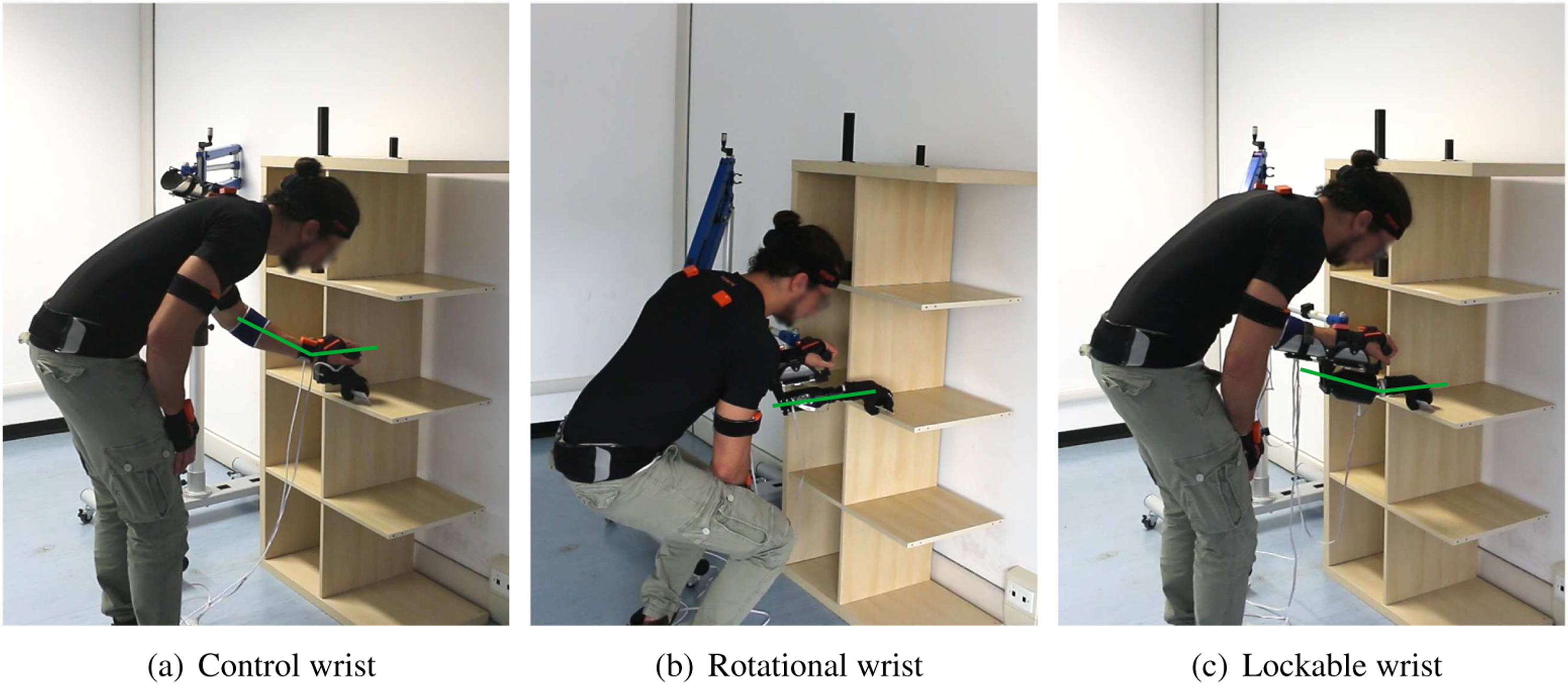
Results from interaction tests highlight the importance of the increased range of motion of the LW at certain conditions. The RW is essentially used for the cylinder (almost 100% of wrist activation) regardless of the height. This is proved by the absence of intra-RW differences among heights (Figure 12) and a percentage of active use in each of height condition close to 1/3. Contrarily, the LW is also intentionally used for other objects depending on the height level.
Although results from wrist activation and execution time are encouraging for both prosthetic wrists, they highlight as well possible difficulties in their control, and especially for the RW. In the left side of Figure 12, we observed some involuntary wrist use as RW ≠ 0 for the card or cube, where prono/supination was not an intended movement. Indeed, Table 4 shows that all able-bodied participants using the RW performed a top grasp (initial hand configuration of the experiment) for these two objects. In addition, the use of the LW may not be intuitive for able-bodied subjects in some occasions. For example, when participants combine pronation and abd/add. for the grasp of the cylinder, we observed a lack of intuitiveness in orienting an external device. This is visible in Figure 13, where the execution time for LW
One of the limitations in recording body configuration of the participants is that differences in the setup might have negative effects in the trajectory decided. The gravity compensator (only used for the robotic aids) could be interfering with the natural trajectory and the final configuration. This is visible only in the shoulder abd/add. angle (see Figure 17) at low- and medium levels, where CW is higher than the prosthetic aids (i.e., more distant from a stand straight up posture). However, as the same setup is used for both robotic systems, their results are comparable.
Generally, results for LW regarding the reduction of compensatory movements are positive. With a more anthropomorphic design, the LW allows subjects to naturally orient the hand in 3 DoF. One example is at the elbow flex/ext. angle (Figure 14), where for the low-level, which was the hardest, LW is significantly better than RW. Subjects often used the LW for performing flex/ext. or abd/add. at extreme height conditions, which are missing DoFs in the RW. In addition, even though both prosthetic systems allow hand rotation to grasp the cylinder laterally, LW enables the combination of prono/supination with abd/adduction movements. Results from the shoulder abd/add. angle in Figure 17 suggest that these combinations are meaningful to obtain a more natural grasp (closer to CW).
Another interesting effect observed in the results is the compliant condition of the proposed system (LW). In the medium level, subjects mostly activate both LW and RW for the grasp of the cylinder. The small but significant improvement in the trunk abd/add. angle in Figure 18 suggests that this progress could be attributed to wrist compliant behavior in its adaptable state. Finally, results for the trunk flex/ext. angle (see left side of Figure 16) suggest an improved posture of LW, especially for the card. This is important because it indicates that even if the SHP (the robotic hand used in all conditions) can adapt towards the object and be useful for the grasp of flat objects, the use of wrist flex/ext. (as occurs only in LW) favors even a more natural grasp.
A natural approach in grasping is fundamental to determine a comfortable user’s body posture. Regarding the RW, the execution of 45° rotation requires a more precise control of the wrist than 90°. Note that for the cylinder, where both prosthesis aids were used for all conditions, the percentage of grasps including 45° with the LW is always higher or equal than for the RW (see Table 4). This suggests a more intuitive use for the LW or a higher interest in pre-shaping the joint in many participants. In able-bodied subjects, we observed that the percentage of P-S 45° for the RW is higher at low- and high levels when grasping the cylinder. These results suggest that extreme height levels represent a more challenging condition and subjects usually pay more attention to grasp the object safely. In agreement with the previous, the LW was not intentionally used only at the medium level for the card and cube, probably because a top grasp was preferred for these objects, and the objects were in a height close to subjects’ natural workspace.
The assessment of a system acceptance is especially important in the prosthetic and rehabilitation field, as devices become part of users’ body. Regarding the self-evaluation surveys, results from able-bodied subjects highlight the potential of the proposed system, which could be a valid alternative for natural grasp approach.
6.2. Subject with limb loss
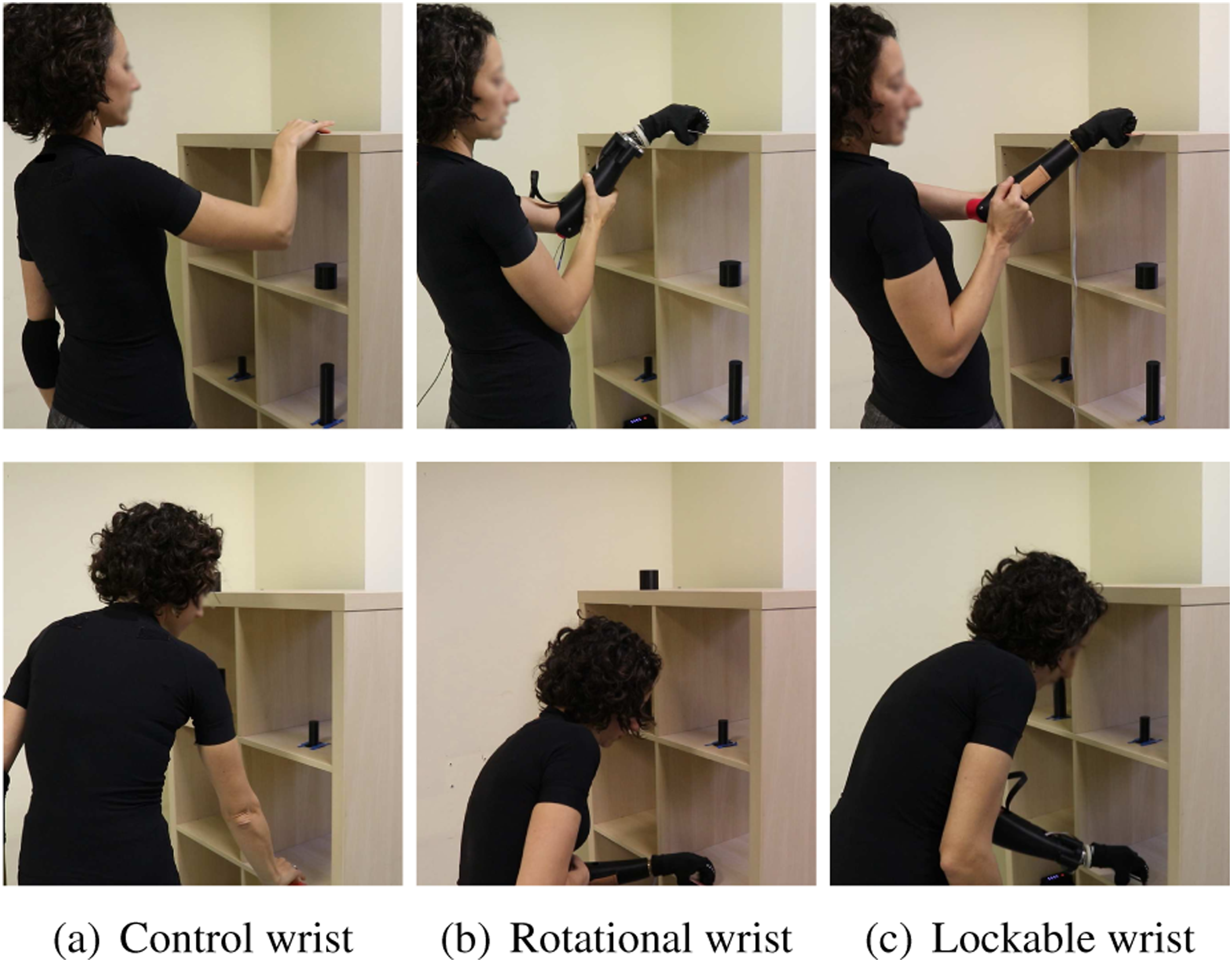
Due to the lack of biomechanical measures for the prosthesis user, we present a qualitative comparison of grasp naturalness in some particular cases (see Figures 20 and 21). Here, the control case consists of the user’ intact arm, which results in hand dexterity differences. This clearly influences the decision making to approach an object and consequently, defines the whole body posture. Still, the LW showed good functionalities and resulted as an intermediate performant wrist, between the intact arm and the RW characteristics. Similarities between the CW and the LW are observable, and in some cases the combination of DoFs, voluntarily selected by the participant, result in a more natural body configuration. Difficulties encountered with the RW are visible as well, which may lead to a larger cognitive load to grasp the object safely. Example of body configuration from a prosthesis user grasping a cylinder in the high level height. Examples of body configuration from a prosthesis user grasping a card in different heights.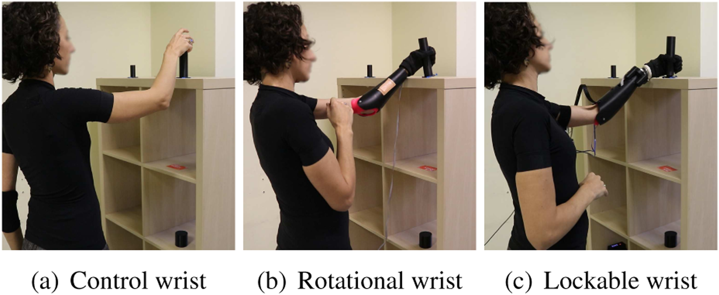
Regarding the prosthesis user observations from Table 4, although the design of the LW shows similarities with the control case motions, a reduced number of DoF included is observed. This could occur due to differences in the setup, difficulties in the control due to the weight of the prosthesis, or because of the difficulties encountered to reproduce human dexterity in motion control when using an external robotic device. Only in 33.33% of the occasions, the user performed a completely different grasp approach with the LW compared to the intact arm (control), corresponding always to the cube. While the user chooses a lateral approach at 45° with the intact hand, she preferred a top grasp for both prosthetic aids. Due to the availability of the DoFs required at the wrist joint with the LW, differences between the intact and robotic approaches could concern the end-effector capabilities. In fact, in the CW, the participant exploited the dexterity of her intact fingers to hold the object, while in the case of the SHP, the alignment of the palm towards the object is fundamental for a successful grasp.
In regards to the self-evaluation surveys, the difference perceived between both robotic solutions is more evident for the prosthesis user. While in 6% of the 33 questions, able-bodied subjects preferred the rotational wrist (none with statistical significance), the prosthesis user never favored this commercial joint. This effect is also highlighted by the SUS score and the average satisfaction rate (last row in Tables 5 and 6, respectively). Despite the LW SUS score for the prosthesis user (52.50) does not reach the standard value for good acceptance (68—average in the literature), it presents a much higher score than the RW (20.00). We believe this occurs because of its prototype design, far from a lightweight product, which may have a strong effect in real users. The prosthesis user reported free additional comments during the self-evaluation. There, she mentioned the difficulties encountered in intuitively controlling the rotational wrist and especially appreciate the simple use of the lockable wrist to change the configuration of the end-effector as a whole, instead of controlling each DoF individually and in sequence, which is burdensome.
6.2.1. Qualitative observations in ADL
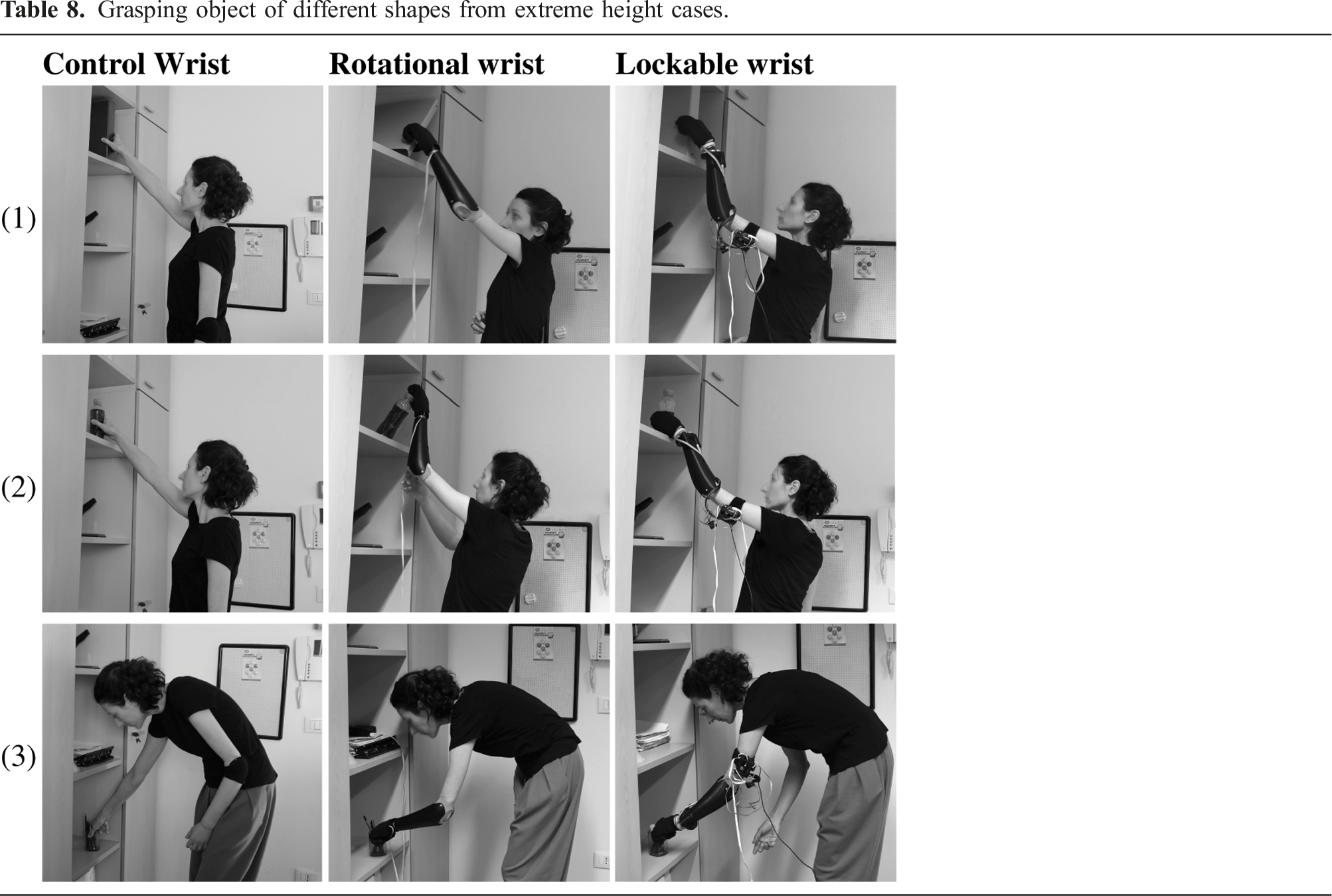
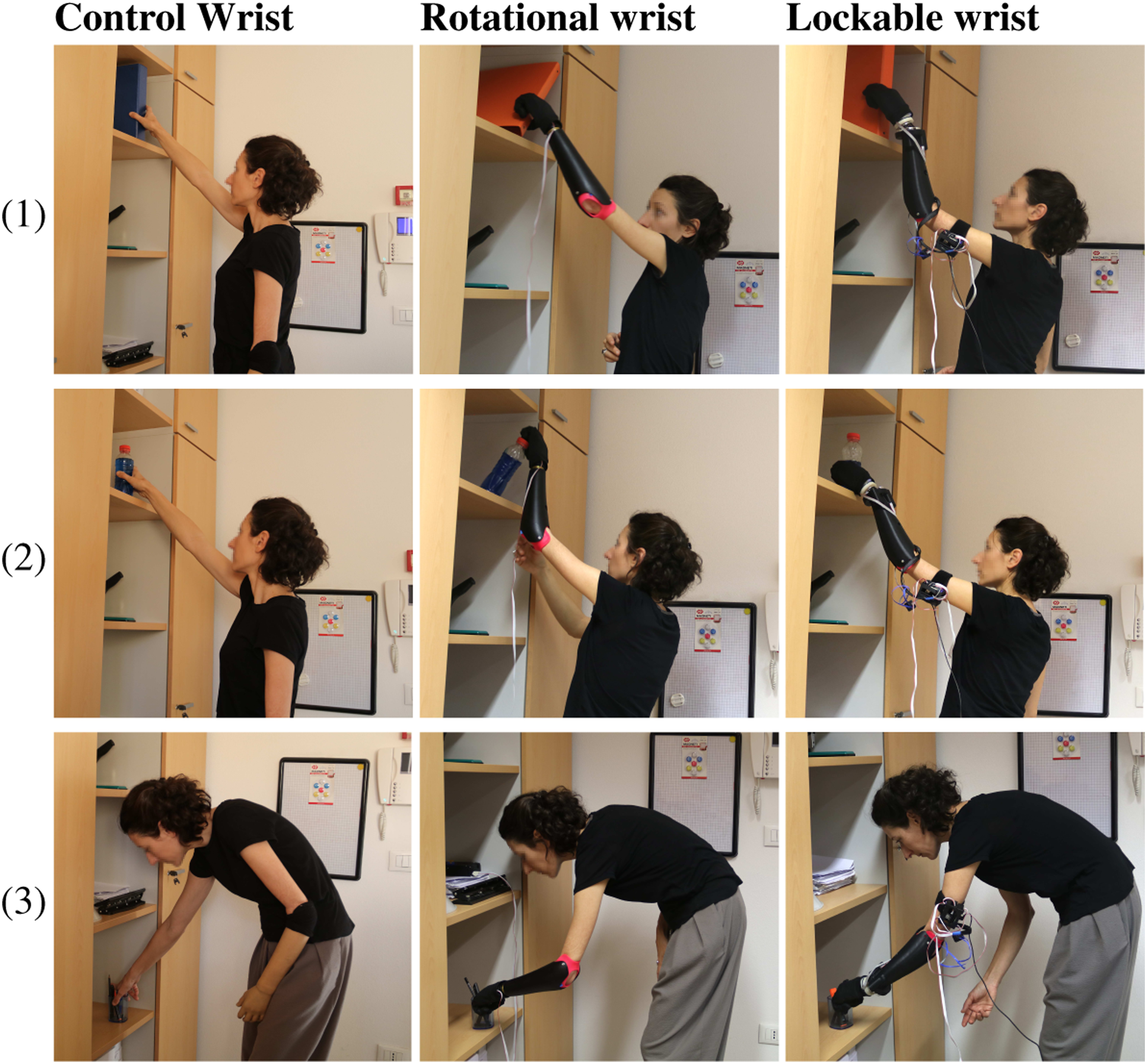
Grasping object of different shapes from extreme height cases.
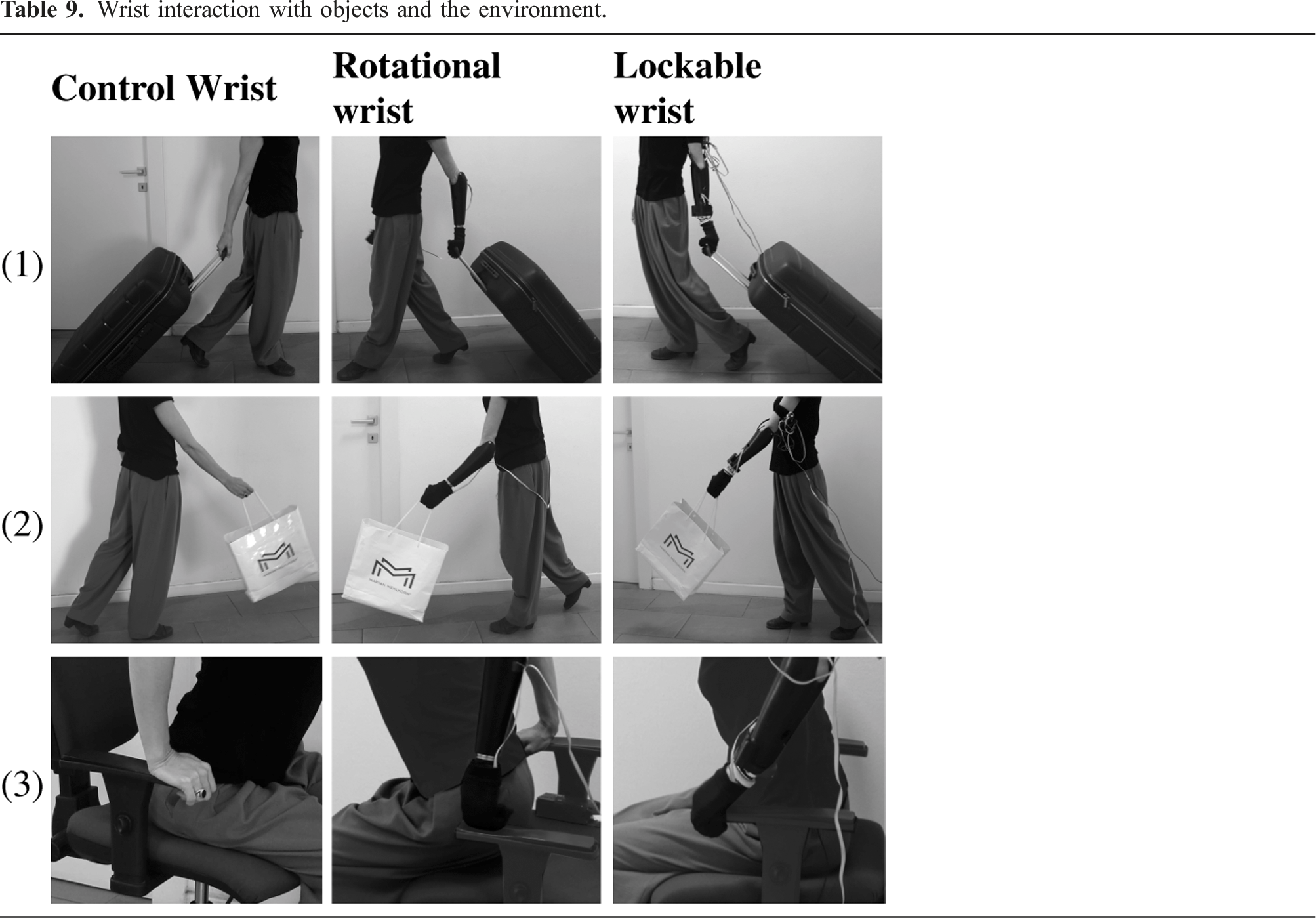
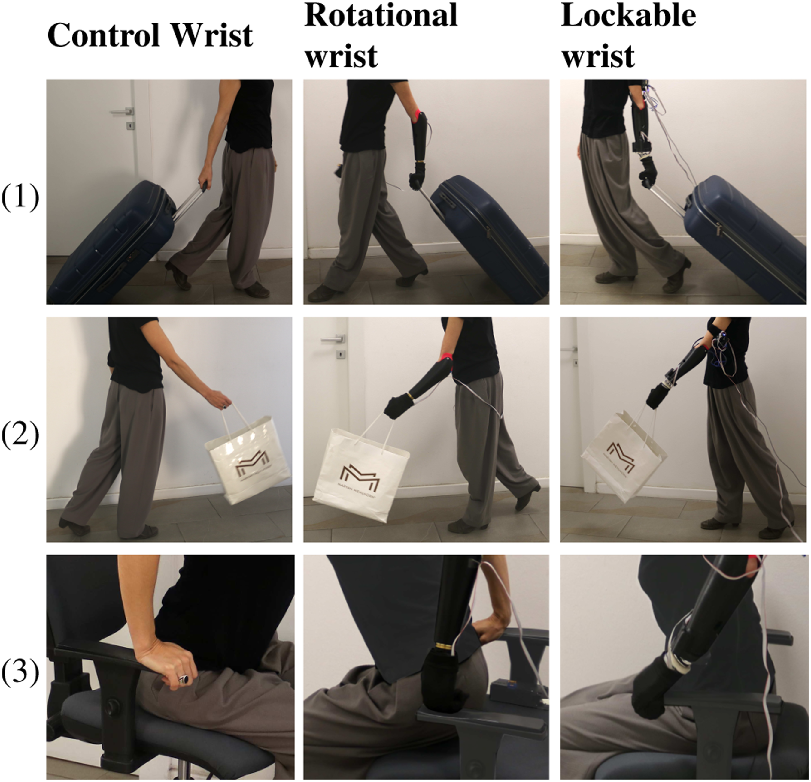
Wrist interaction with objects and the environment.
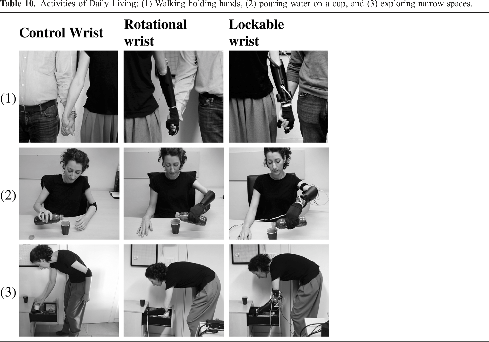
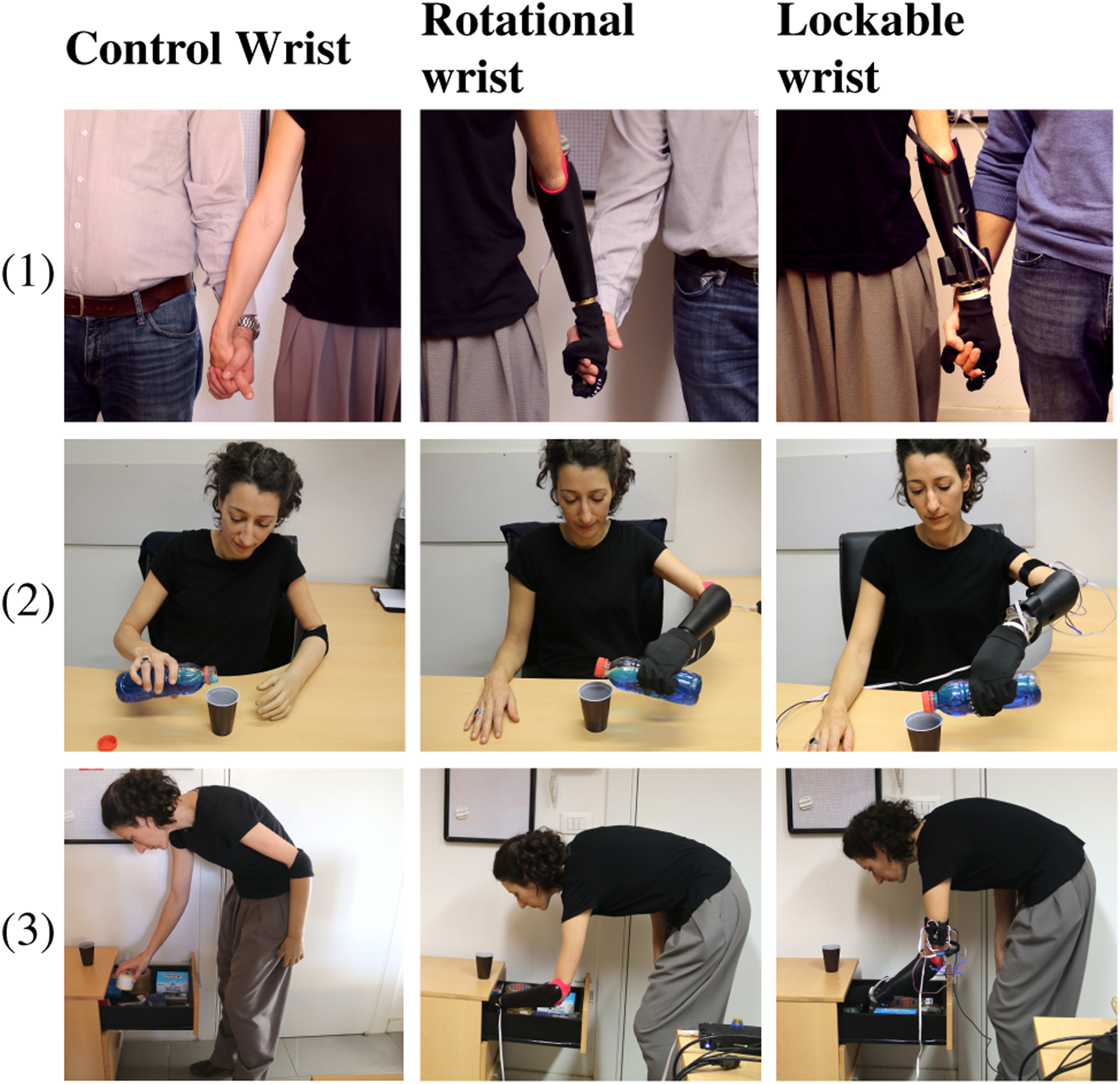
Activities of Daily Living: (1) Walking holding hands, (2) pouring water on a cup, and (3) exploring narrow spaces.
7. Conclusions
In this paper, we propose a simple yet useful 3-DoF wrist joint with adaptable and rigid properties. The friction-locking capability enables the adjustment of hand configuration in pre-grasping phases, and the control of the hand and wrist motion independently. Besides, the compliant behavior in F-E and A-A allows a soft interaction with the environment. In addition, this design of 3 DoFs with a simple control strategy offers the unique opportunity to evaluate the effect of an increase in wrist ROM on users’ performances.
In this study, our primary focus was not only on stiffness switch (stiff/locked or unlocked/compliant) according to tasks (or grasping phases) but also on providing additional DoFs and examining their usage patterns. Given the return mechanism (due to the compliant interface described in section 3.2.1) to a Rest position of the wrist when aiming for a more stable grasp, it often entails a switch in stiffness to secure this hand configuration during the pre-grasping phase. Considering the scope of this study and the numerous research questions addressed, we focused on body configurations related to various wrists, objects, and height levels, instead of assessing intermediate stiffness values and their potential, which the authors anticipate exploring in the future. Moreover, it is important to note that our control scheme, while providing discrete control between wrist and hand, also allows for proportional control of wrist rotation in RW. However, the rapid muscle activation required for entering to the wrist joint state can limit the precision of human muscle control afterward. Furthermore, the limited range for full locking in the LW can hinder the ability to finely adjust its stiffness or friction to intermediate levels. If fine-grained control is a primary requirement, an alternative myoelectric control method would need to be proposed in the future to allow for a more intuitive use of the system (Capsi-Morales et al., 2020).
Results evidence the feasibility of the prototype, its enhanced performance, and present the first impression of the participants. Experimental results from functional tasks proved a significantly larger active usage of the lockable wrist (LW) than a conventional rotational wrist (RW). A substantial increase in the usage of the LW occurred in extreme height conditions where subjects perform F-E, A-A, or a combination of the previous with P-S to better approach the target objects. Note that those wrist configurations are unavailable for the rotational wrist. Moreover, the LW use did not compromise the time execution of the overall prosthesis (both systems around 19s), hence improving only wrist functionality. Concerning compensatory movements, interaction tests proved that when there was significance, results always favor the LW over the RW, also showing a closer resemblance to the control wrist (CW). The self-evaluation surveys reported a significant preference of the LW in questions concerning control intuitiveness, good integration, comfortability and perception of a decrease of compensatory movements, and performance speed. The average satisfaction and SUS scores also resulted significantly higher for the LW, suggesting the acceptance of the proposed system. A similar tendency is observed in prosthesis user’s answers. Finally, a preliminary evaluation in ADL suggested enlarged capabilities regarding intuitiveness, grasp safety, and softer interaction. While the data from experiment
Even though the lockable wrist is designed to permit its orientation through the environment and/or the intact hand, the subjects modified the wrist joint with the assistance of the intact hand during the experiments. The passive modification of the end-effector orientation through the environment is not trivial and could negatively affect the execution time. However, this feature could be especially convenient for bilateral amputees.
The limitations of the study include the lack of control over shelf heights during the experiment in relation to participant heights, potentially impacting wrist usage variations. It is worth noting that more recent and comprehensive functional assessments for patients, such as ACMC (Hermansson et al., 2005), AM-ULA (Resnik et al., 2013), and CYBATHLON tasks (Jaeger et al., 2023), have made efforts to incorporate various grasping and releasing scenarios in different configurations. This is intended to address the previously overlooked aspect of wrist motion during grasping or standard functional assessments. Furthermore, the study could benefit from a more diverse set of objects, which was limited by the experiment duration. We hope that our study can draw attention to the need for standard assessments in more complex scenarios, prompting the development of controlled tests with comparable setups.
Despite the limitation of involving a single prosthesis user, we believe that the statistical analysis of able-bodied participants’ data still provides valuable insights into the significance of wrist DoFs and underscores the need for more comprehensive systems in achieving dexterous manipulation. Due to the encouraging results, future works will encompass an extensive evaluation with a larger group of prosthesis users and point towards a more compact and light design with a larger range of motion. Future research endeavors should present a more refined joint design with variable impedance, where a comprehensive characterization of the friction and impedance will be a central focus to further advance the field. For precise control of wrist stiffness levels or simultaneous control of both wrist and hand properties, a more advanced myoelectric control method would need to be proposed in the future.
8. Appendix
Due to the physical inter-subject differences and possibly not exact starting position relative to the height differences in subjects, we considered the average angle from a window (3 samples) right after the successful grasp event (dashed red line in Figure 22), where desired/needed subject body configuration is stable. We defined the successful grasp event at the instant with the 50% hand total closure from the last complete closure executed for that experimental condition. Example of compensatory movements from a subject in a particular case: grasping the card at the low-level height (2nd repetition). The part before the dashed red line refers to the reaching and grasping phase, while the second part refers to the transport and release phase of the action.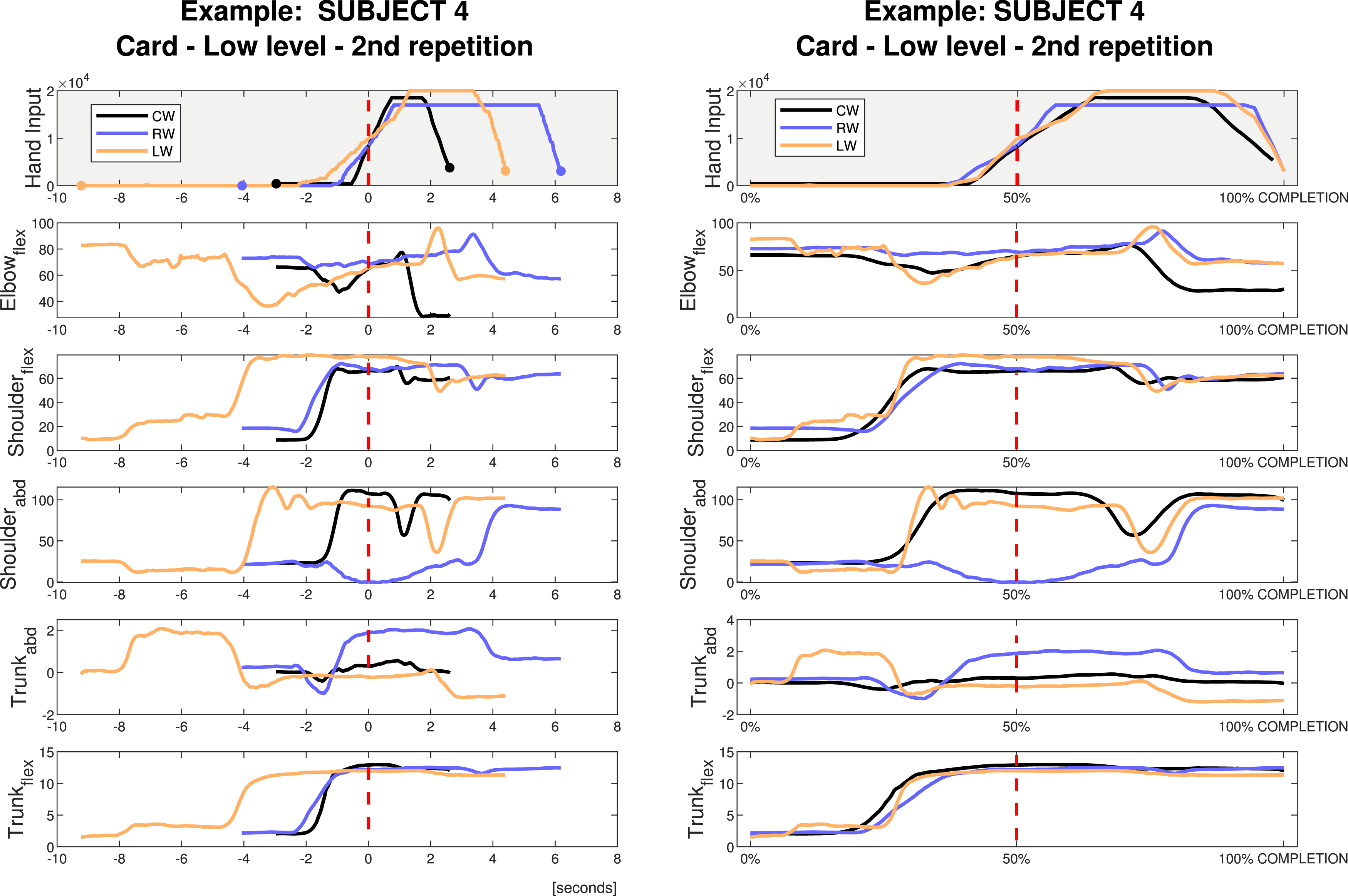
An example of the data obtained from Xsens and the motor encoders is presented in Figure 22. The reference configuration of the prosthetic hand and its division into two phases by a red dashed line is shown in the first row. The first phase represents the reaching and grasping of the action, while the second represents the transport and release phase. In the left column, the data from the three wrists is synchronized by the middle event (successful grasp). The x-axis represents the execution time with a marker that indicates the starting and the ending of the action. The rest of the rows represent the 5 joint angles selected to study the range of compensatory movements. This column allows the visualization of the time needed to reach the object and perform the task. On the other hand, in the right column, the data is almost overlapped. There, signals are synchronized by the duration of each phase over the percentage of completion. Therefore, while the left column normalizes the time, giving t = 0 at the successful grasp event, the right column stretches the signal until the three wrists get a common duration. The right column facilitates the understanding of the similarities and differences between wrist use and body angles.
Footnotes
Acknowledgments
The authors warmly thank Mattia Poggiani and Andrea Di Basco for their valuable help in the realization of the experimental validation and the manufacturing of the system pieces, respectively.
Declaration of conflicting interests
The author(s) declared no potential conflicts of interest with respect to the research, authorship, and/or publication of this article.
Funding
The author(s) disclosed receipt of the following financial support for the research, authorship, and/or publication of this article: This research has received funding from the European Union’s Horizon 2020 Research, ERC programme under the Grant Agreement No. 810346 (Natural Bionics). The content of this publication is the sole responsibility of the authors. The European Commission or its services cannot be held responsible for any use that may be made of the information it contains.