
Abstract
The learning-from-observation (LfO) paradigm allows a robot to learn how to perform actions by observing human actions. Previous research in top-down learning-from-observation has mainly focused on the industrial domain, which consists only of the real physical constraints between a manipulated tool and the robot’s working environment. To extend this paradigm to the household domain, which consists of imaginary constraints derived from human common sense, we introduce the idea of semantic constraints, which are represented similarly to the physical constraints by defining an imaginary contact with an imaginary environment. By studying the transitions between contact states under physical and semantic constraints, we derive a necessary and sufficient set of task representations that provides the upper bound of the possible task set. We then apply the task representations to analyze various actions in top-rated household YouTube videos and real home cooking recordings, classify frequently occurring constraint patterns into physical, semantic, and multi-step task groups, and determine a subset that covers standard household actions. Finally, we design and implement task models, corresponding to these task representations in the subset, with the necessary daemon functions to collect the necessary parameters to perform the corresponding household actions. Our results provide promising directions for incorporating common sense into the robot teaching literature.
Keywords
1. Introduction
In recent years, there has been a growing demand for service robots that can assist the elderly. Many elderly people now live in senior residences, and the shortage of caregivers is becoming an issue. Further, although their residences are comfortable and well supported, the elderly still want to live in their own homes whenever possible. It is important and urgent to develop service robots that can support the lives of the elderly in senior residences and/or in their own homes to meet these needs.
The learning-from-observation paradigm is a promising direction toward this goal. A learning-from-observation system observes human actions and learns how to perform those actions based on the observations. In senior residences and at their own homes, we can assume that nurses and caregivers care for patients at least part of the time. During their presence, the nurses or caregivers would be expected to train robots using a learning-from-observation system instead of manual programming. In addition, even though each home has a large variation in the environment, if necessary, such nurses or caregivers can tune up the robot’s actions through their on-site demonstrations to absorb the environmental variations. Furthermore, the time available to nurses or caregivers for demonstrations is often limited, and learning-from-observation has an advantage over other similar demonstration-based methods because the task knowledge embedded in the system in advance allows the necessary behaviors to be learned from a small number of demonstrations, often just one demonstration.
This paper defines top-down learning-from-observation as a method in which a robot can generate a program in one or a few demonstrations using predefined top-down templates. Namely, top-down learning-from-observation is defined as the method of adding human hints to the automatic programming methods developed in the robotics community. On the other hand, this paper defines bottom-up learning-from-demonstration as a method in which a robot can generate an action from multiple bottom-up observations. These are in the vein of reinforcement learning, which has been developed in the machine learning and neuroscience communities. In fact, this paper narrowly defines only those top-down methods with predefined templates as top-down learning-from-observation, by respecting Professor Raj Reddy’s original naming of the top-down method 1 at CMU in 1988. Professor Raj Reddy stated in the article (Reddy, 2003) that “Professor Katsu Ikeuchi of CMU (currently at Tokyo University) demonstrated in 1988, a robotic system capable of learning from observation,…Professor Ikeuchi, instead, chose to derive the robot actions required, by inferring (planning) the sequence of actions given the beginning and end states of the scene.” Indeed, in the field of machine learning, bottom-up methods that learn actions only from observations are sometimes referred to as learning-from-observation (Lee et al., 2019; Torabi, 2019; Yang et al., 2019). However, we will follow Professor Raj Reddy’s original definition and refer only to top-down methods as top-down learning-from-observation. In the absence of confusion, for the sake of simplicity, top-down learning-from-observation can be written simply as LfO, while the bottom-up methods, including those referred to as bottom-up learning-from-observation in the machine learning community, are collectively referred to as learning-from-demonstration (LfD).
So far, most top-down learning-from-observation systems have been developed for relatively clean environments such as machine assembly in industrial settings as done by Ikeuchi and Suehiro (1994) or rope handling in laboratory settings as done by Takamatsu et al. (2006). The home environment is cluttered and household actions have large variations that require common sense to understand and perform the actions. To overcome this cluttered environment, Wake et al. (2020b) proposed a verbal-based focus-of-attention mechanism to direct the system’s attention to the places where the key actions occur. In this paper, we overcome the remaining problem of understanding household actions that require common sense.
To understand household actions, it is necessary not only to observe the demonstration but also to use common sense that follows from the purpose of the actions. For example, in the case of wiping a window, it is necessary to have the common sense that the mop must maintain contact with the window surface while wiping; if one only considers the possible physical states between the tool (mop) and the environment (window), and without common sense, the mop may detach and move freely away from the surface.
Previous top-down learning-from-observation research has focused only on the real physical constraints between the tool and the environment. We bring common sense to the paradigm by explicitly describing common sense explicitly in terms of imaginary semantic constraints. For example, in the previous wiping example, the wiping action is described by introducing an imaginary semantic wall in parallel to the wiped surface, and the mop can only move between these two surfaces: one physical and the other semantically defined imaginary surface.
The goal of this paper is threefold. First, using Kuhn–Tucker (Kuhn and Tucker, 1957) and Screw (Roth, 1984) theories, we enumerate possible state transitions that occur due to translational or rotational displacements that exist between a tool and an environment. These state transitions provide the upper bound of possible household actions. We then analyze cooking videos using these state transitions and categorize frequently occurring physical and semantic constraints into task groups.
Second, for top-down learning-from-observation, we build a system to recognize these groups using textual/verbal input as a source of information. Task group recognition is highly dependent on the tool and environment involved in the task. Such information is relatively easy to obtain from textual/verbal input and can be trained at low cost compared to image recognition, which requires many training data to cover different demonstration environments.
Third, we aim to design task models associated with each task group. A task model is a framework for the actual robot execution of a task group and has a structure similar to Minsky’s frame (Minsky, 1988): a frame corresponds to a task group and has slots corresponding to the parameters required to execute the task group. In Wake et al. (2021a), it was shown that these parameters can be effectively obtained using the procedures assigned to each slot with the focus-of-attention mechanism. In this paper, we extend this idea to cover semantic constraints and design task models for physical and semantic tasks.
The contributions of this study are as follows: • To the best of our knowledge, this is the first paper to investigate the full set of contact states and state transitions, under the definition of that each task as a face contact transition in translation and rotation displacements between a tool and its environment. • We introduce a novel approach to represent common sense in household actions using proposed semantic constraints, and the appropriateness of the representation is shown against top-rated household YouTube videos as well as real home cooking recordings. Furthermore, the common constraint patterns are organized into task groups. • We define task model designs to represent the semantic constraints as robot executable knowledge and implement such models using a vision system.
The remainder of this manuscript is organized as follows. Section 2 introduces related work and clarifies the goal of this paper. Section 3 establishes the basic description of states and state transitions of rigid objects. Section 4 introduces semantic and physical constraints from the state transitions. Section 5 analyzes household actions using these constraint representations and extracts frequently occurring constraint patterns as task groups. Section 6 presents experiments to recognize task groups in an LfO system using verbal input. Section 7 provides an overview of task models associated with the physical task groups and shows how the same idea applies to the semantic task groups. Section 8 proves that by using the results of Section 6 and the design in Section 7; it is possible to construct such task models using a real multimodal input system. Section 9 provides a summary of this work and discusses the characteristics of the system and future research directions.
2. Related works
This study addresses the problem of communicating common sense, which we refer to as semantic constraints, in the context of robot teaching. We define semantic constraints as imaginary constraints on actions that are necessary to accomplish certain tasks and that are difficult to obtain directly from observation. We propose the use of linguistic input to recognize such semantic constraints. The position of this section is explained by reviewing previous robot teaching frameworks with respect to the representation of motion constraints and the use of verbal input. The literature review focuses on studies of object manipulation; non-manipulative applications such as navigation are beyond the scope of this study.
2.1. Representation of motion constraints in robot teaching frameworks
The top-down learning-from-observation is a robot teaching framework that aims to map one-shot (or at most a few shot) demonstrations to robot movements using intermediate task representations referred to as task models (Ikeuchi and Suehiro, 1994; Takamatsu et al., 2006, 2007; Nagahama and Yamazaki, 2019; Perez-D’Arpino and Shah, 2017; Subramani et al., 2018). In a typical LfO system, a task is defined as the transition of object states, such as the contact state between polyhedral objects for part assembly in Ikeuchi and Suehiro (1994) or the topology of a string for knot-tying in Takamatsu et al. (2006). To extend the LfO construct to household actions, Wake et al. (2021a) recently reported an LfO system that supports motion constraints derived from linkage mechanisms, and the task representations were mapped onto robots of various configurations by Sasabuchi et al. (2020). Although these systems achieved success in specific task domains, the tasks were defined using only physical constraints; semantic constraints were ignored. Theoretically, LfO can cover motions that include semantic constraints, provided a set of appropriate task models is assigned. However, to the best of our knowledge, there is no LfO framework that deals with semantic constraints.
Learning from demonstration and programming by demonstration are also popular frameworks for robot teaching. In this paper, we refer to these bottom-up methods collectively as “LfD.”
The central theme in LfD is to obtain state-action pairs or policies from the bottom up, through observation of repeated demonstrations (Argall et al., 2009; Billard et al., 2008; Schaal, 1999). Indeed, since human demonstrations reflect human intentions, LfD systems can learn manipulations with semantic constraints (e.g., scooping things while avoiding spillage in Akgun et al., 2012, pouring in Dwibedi et al., 2018) and physical constraints (e.g., block building in Orendt and Henrich, 2017, rotating in Liu et al., 2019). However, because policy learning is based on imitating human movements, the learned manipulations do not come with an explicit understanding of the semantic constraints. In addition, the data obtained are prone to error because the semantically constrained important parts of the data are not explicitly indicated during teaching/demonstration. Although several LfD studies have incorporated robot experience by applying reinforcement learning (Balakuntala et al., 2019; Guenter et al., 2007) or meta-learning (Yu et al., 2018), they do not aim to learn semantic constraints.
In summary, LfO and LfD both have the potential to deal with semantic constraints, but they differ in the design concepts of intermediate task representations: while LfO attempts to explicitly teach constraints using top-down knowledge, task models of state transitions, LfD uses iterative human demonstration with learning in bottom-up learning. LfO systems require only a smaller number of demonstrations, because in LfO, the semantic constraints are explicitly given from the task models, whereas in LfD, these constraints themselves must first be discovered from the demonstrations. The time available for nurses and caregivers to perform such demonstrations is often very limited. Thus, LfO has an advantage over LfD because the task knowledge previously embedded in the system enables the acquisition of necessary actions from a single demonstration. In addition, the LfO system knows which parts of the entire demonstration are important, and the system uses the data from those parts and ignores the rest, which has the advantage of reducing fatigue during the demonstration.
This study leverages LfO to propose a solution that operates within the understanding of a task’s purpose by defining state transitions that take into account semantic constraints.
2.2. Use of language in robot teaching
The problem of recognizing semantic knowledge from language is a form of “symbol grounding.” The accumulated evidence suggests that linguistic symbol grounding can solve a variety of problems in robotic applications. Examples include video object segmentation in Khoreva et al. (2018), visual and verbal navigation in Anderson et al. (2019), human-robot cooperation in Petit et al. (2013); Liu and Zhang (2019), interactive learning in Chai et al. (2018); Mohan et al. (2012), and bidirectional mapping between human movement and natural language in Plappert et al. (2018). By focusing on the function of language to provide semantic grounding, robot teaching applications have addressed linking an instructor’s linguistic input to execution operations (e.g., picking–placing in Forbes et al., 2015; Lueth et al., 2002, grasping in Ralph and Moussa, 2008; Wake et al., 2020a, 2021b, virtual-block relocation in Bisk et al., 2016, and mobile manipulation in Howard et al., 2014; Tellex et al., 2011). Innes and Ramamoorthy (2020) propose that experts elaborate on the original demo by adding additional specifications.
These studies support the idea that language can provide promising cues for estimating semantic knowledge related to object manipulation. However, few methods have been proposed that explicitly formulate semantic constraints on manipulation and use language to reason about these constraints. Recent work closely related to our study exists in Paulius et al. (2019, 2020). In these studies, the authors define a taxonomy of manipulation motions for cooking, called motion codes, and they relate each motion code to verbs. A motion code is defined in terms of contact states and motion trajectories, and covers a wide range of actions. However, they lumped together actions with (e.g., pour) and without semantic constraints (e.g., pick-and-place). In contrast to their approach, we propose an action class based on motion constraints. We also try to highlight the role of language in the recognition of semantic constraints by examining the correspondence between action classes and instructional texts: not just the correspondence between verbs.
3. Defining contact states in translation and rotation
To characterize the state of an object, admissible displacements of the object/tool (e.g., a mop) with respect to its environment (e.g., a floor) are discussed using the screw theory (Roth, 1984). The object states and their transitions are used to understand the physical and semantic constraints involved in household actions. In particular, the following discussion assumes that the tool or the object has already been grasped and considers the contact relationship between the grasped tool or object and an environmental object. Regarding a flexible object (e.g., sponge), it is necessary to consider its flexibility during grasping. However, once it is firmly grasped, it is assumed that it can be handled in the same way as a rigid object in terms of its contact relationship. Furthermore, we do not consider object dynamics (e.g., spilling) by assuming that the motion of the robot during execution is relatively smooth and stable.
3.1. Characterizing admissible displacements
The admissible displacement of a rigid body is constrained by rigid environment objects through point contacts. We assume that the constraint points have neighborhoods that can be approximated as planar patches, thereby guaranteeing differentiability at each contact point. Furthermore, we do not consider singular cases such as two polyhedrons contacting with a common edge, because such singular cases rarely occur in household action domains.
3.1.1. Constraint inequality equation
An admissible displacement of a rigid body is formulated using the screw theory (Roth, 1984), which formulates a translational displacement along the screw axis and a rotational displacement as a circular displacement around the screw axis. Any displacement constraint, given by a contact point
From this equation, we obtain
To simplify the analysis here, we will assume either pure translation or pure rotation. Even with this assumption, many useful household tasks can be represented. Certainly, some household tasks, such as screw tightening or ladle scooping, are a mixture of translation and rotation. However, in the former case, the translational displacement is considerably smaller than the rotational displacement. Therefore, such actions can be considered pure rotation in terms of representation. In the latter case, when performed by a robot, it can be divided into first translational and then rotational displacement. Thus, we do not consider this assumption to be critical when considering household tasks.
For a pure translation motion, p = ∞,

For a pure rotation motion, p = 0,

3.1.2. Gaussian sphere and axis directions
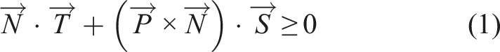
We use a Gaussian sphere (See Gauss and Pesic, 2005; Horn, 1986) to depict the screw axis. A screw axis is represented as a 3-dimensional (3D) unit vector, Gauss mapping and Gaussian sphere. A unit vector is mapped to a point on the Gaussian sphere. Its starting and the end points are projected to the sphere center and its spherical point, respectively. The point represents the vector.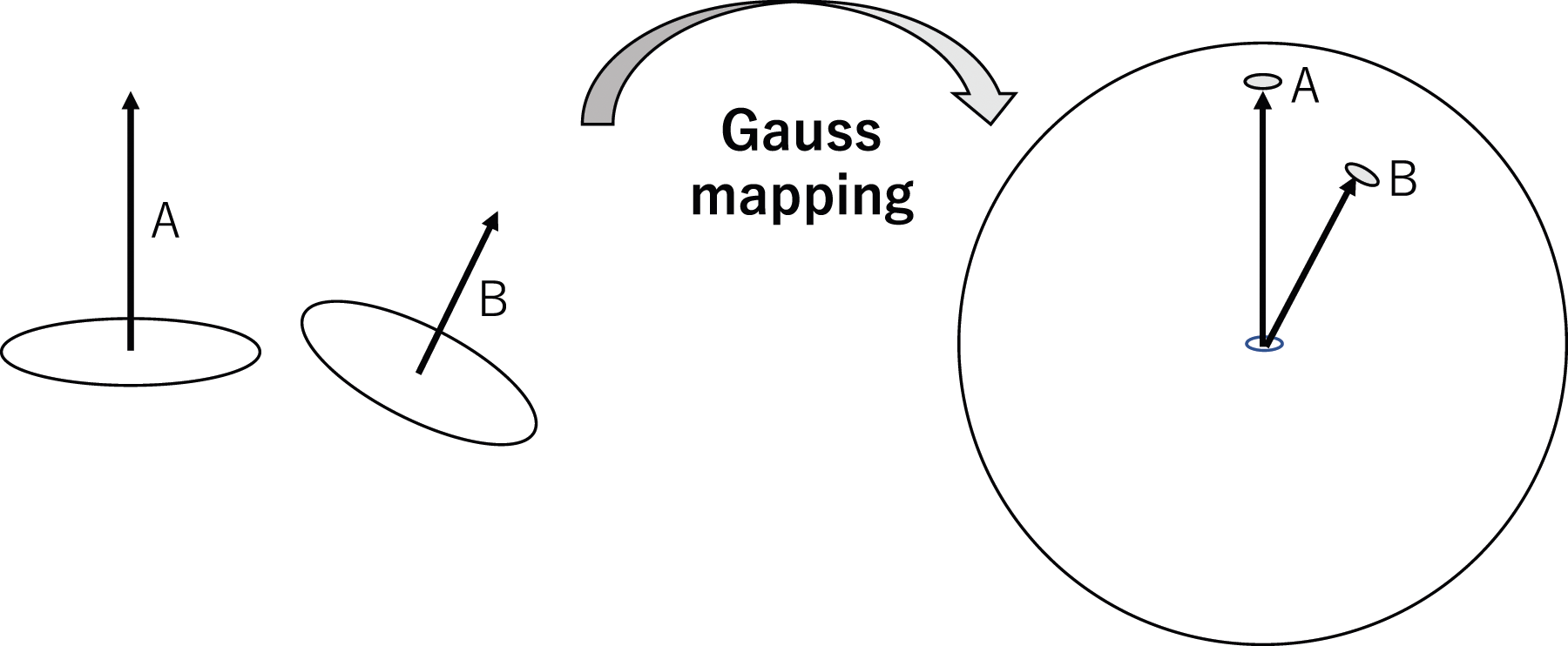
3.1.3. Pure translation
In pure translational motion, any motion direction is aligned to the axial direction. Thus, in the upcoming discussion on pure translation, we use axis and motion directions interchangeably. In particular, the spherical surface of the Gaussian sphere represents the space of all possible axis and motion directions.
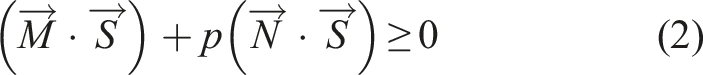
Let us consider the case where a rigid object is constrained by a point contact as shown in Figure 2(a). From equation (3) with p = ∞, One-directional contact. (a) A constraining surface patch has an infinitesimal neighboring region, wherein the normal direction is 
We can set the normal direction,
An infinitesimal motion corresponding to a point on the northern hemisphere breaks this relationship. Among these motion components, the pure motion component is located along the north pole direction.
When a rigid body is constrained by multiple contact points, i, of which normal direction is depicted as
As shown in equation (5), we can collect all normal directions as a coefficient matrix, N, of a simultaneous inequality equation. Depending on the rank of the matrix derived according to the Kuhn–Tucker theory (Kuhn and Tucker, 1957), this solution space can be classified into 10 characteristic patterns: an entire spherical region, a hemispherical region, a crescent region, a polygonal region, an entire great circle region, a great semicircle region, an arc of a great circle, a pair of points, one point, and no region as the admissible axis regions. For the sake of simplicity, we group them into six groups and define them as states as non-contact (NC), planar contact (PC), two-side planar contact (TR), one-way two-side planar contact (OT), prismatic-contact (PR), one-way prismatic-contact (OP) and fully contact (FC) translation states, as shown in Figure 3. Seven translation contact states. For the sake of simplicity, we grouped three partial contact states (i.e., a hemisphere, a crescent, and a polygonal shaped state) into one PC state, and two one-way states (i.e., a hemi-circle and an arc-shaped state) into one OT state.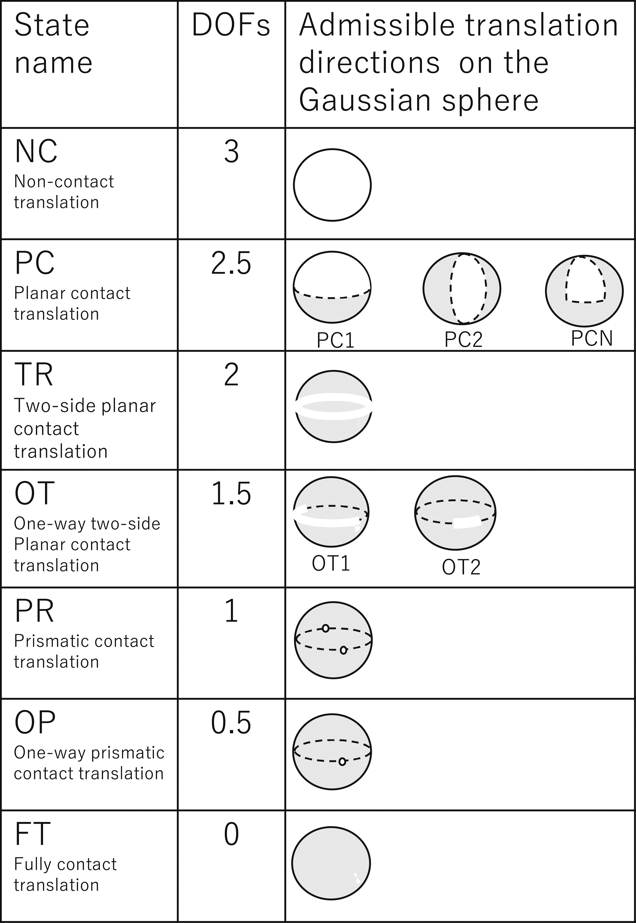
3.1.4. Pure rotation
For a pure infinitesimal rotation, the screw ratio, p, becomes 0, and the equation is represented as
The motion constraint to the screw axis direction,
In the case of the finite rotation, the nonlinearity of the motion when admissible axis directions exist on the great circle in the infinitesimal analysis are not a great circle but a combination of points and arcs that have been proved. See Appendix A for more detailed discussions and proof. In summary, we have 13 topological patterns of admissible axes on the Gaussian sphere: the whole spherical surface, a hemisphere surface, a crescent region, a polygonal region, a combination of arcs and points on a great circle, a pair of arcs on a great circle, two pairs of points on a great circle, a combination of arcs and points on a great semicircle, two points on a great semicircle, one arc on a great semicircle, two points on a great circle, one point, and no region.
For the sake of simplicity, we group these into seven groups: non-contact (NR), rotational contact (RT), spherical contact (SP), one-way spherical contact (OS), revolute contact (RV), one-way revolute contact (OR), and fully constrained (FR) rotation states, as shown in Figure 4. Rotation states.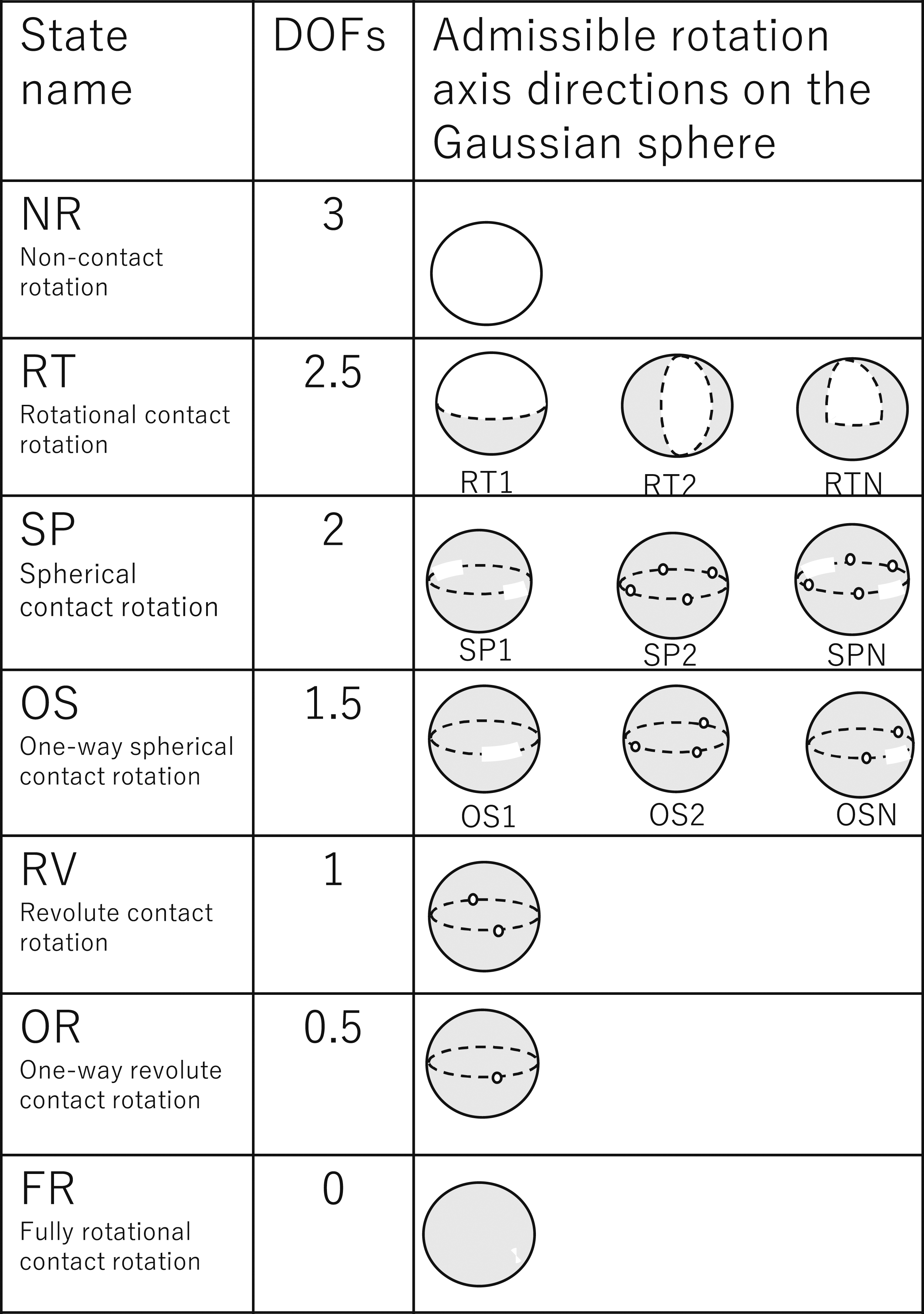
4. Physical and semantic constraints
4.1. Physical constraints and states
We express the degree of freedom of an object by using the admissible axis directions of a screw represented as admissible regions on the Gaussian sphere. This representation is used to describe the constraints for household actions.
Let us consider the example shown in Figure 5. In Figure 5(a), the drawer is pulled out halfway. This condition allows us either to pull it out or to push it in along the drawing direction. The admissible axis directions in translation are represented as a pair of points on the Gaussian sphere: the PR translation state. The drawer cannot rotate around any axial directions, and there are no admissible axial directions on the Gaussian sphere: the FR rotation state. We can label the drawer state as the (PR,FR) state. States of a drawer. (a) Halfway open; One full DoF in translation: a pair of points on the Gaussian sphere, PR translation state. Zero DoFs in rotation: no admissible directions on the Gaussian sphere, FR rotation state. (PR, FR). (b) Fully closed; Half DoFs in translation: one point on the Gaussian sphere, OP translation state. Zero DoFs in rotation: no point on the Gaussian sphere, FR rotation state. (OP, FR).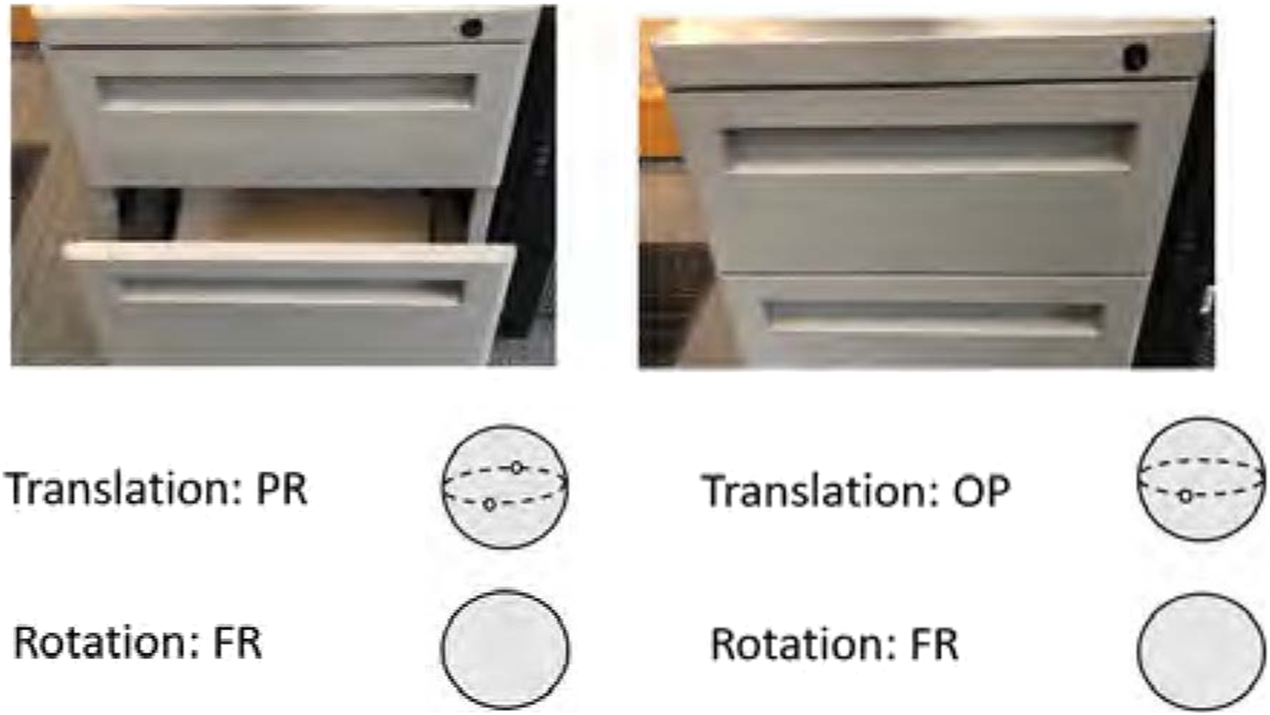
In a completely closed state, as shown in Figure 5(b), the drawer can only move toward the opening direction. The admissible axis direction (i.e., the possible translation direction) is represented as one point on the Gaussian sphere, which is the OP translation state; it cannot rotate as well. Thus, we can label the drawer fully closed as the (OP, FR) state.
Figure 6 expresses the states of various household objects as combinations of translation and rotation states. Some singular cases do not occur in daily life tasks and occur only when special contact arrangements exist. In the figure, these singular cases are shown in terms of the screw center and contact-point arrangement. For example, in the case of PC-FR, the rotation center is located at the center of the diagram and is shown as a black dot. The two contact points are depicted as two ellipses with the arrow indicating the contact normal directions. In this arrangement of contact points and the rotation center, no rotation around any axis direction is possible (FR); only upward detaching transnational motion is possible (PC). Various configurations of contact points and resulting states.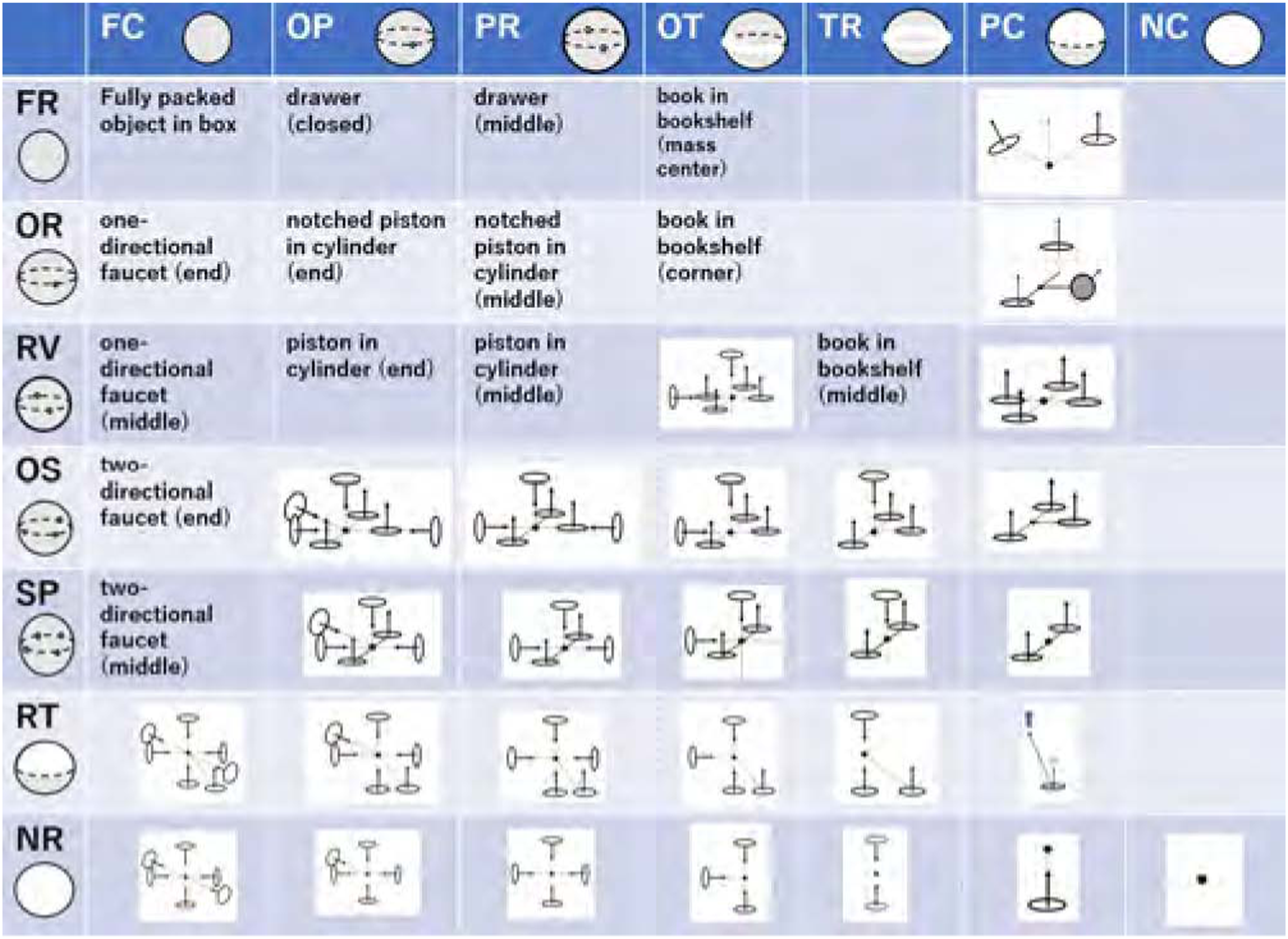
Furthermore, we can add other singular cases as shown in the figure. The DoFs of a rigid body in contact with its environment object depend on where to take the position of the screw axis (i.e., the rotation center). Hereafter, unless the rotation center is specifically described, it is assumed to be inside the convex hull of the object.
4.2. Semantic constraints and states
Apart from the physical constraints provided by the environment, we need to consider the semantic constraints of household actions. Semantic constraints express common sense cues that reflect implied human intentions. Let us consider an example of a cup filled with water. If we rotate this cup along the horizontal axis, the water will spill. Using our common sense, we usually avoid such spills. Thus, we add a semantic constraint, given from the advice of “it is not a good idea to spill the contents when relocating the cup,” the possible axis direction of the cup in rotation during the relocation becomes a pair of points along the gravity direction (i.e., the RV (revolute joint) contact state in the rotation). Thus, by considering the semantic constraint, the state of the cup is represented as (NC, RV) instead of the original (NC, NR).
Another example of semantic constraints is the state of a mop at the beginning of a floor-cleaning action. Under the physical constraints, the state of the mop is represented as (PC, RV), as shown in Figure 7(a). When one begins to clean the floor, the mop should not leave the floor while cleaning. Thus, the translation state under the semantic constraint is the TR. Furthermore, since we plan to clean the inner area from the current mop position, it is allowed to move only in the direction toward the center and not toward outside (i.e., the OT contact state). Thus, the mop state is represented as (OT, RV) instead of (PC, RV), due to the semantic constraints given by the common sense along the cleaning-floor action. See Figure 7(b). Physical and semantic constraints. (a) A mop contacts the floor. It can move upward, and the hemisphere is an admissible region; PC. (b) The mop cannot leave the floor surface because of the semantic constraints obtained through the common sense of “cleaning-the-floor.” The admissible region is an arc of a great circle, OT.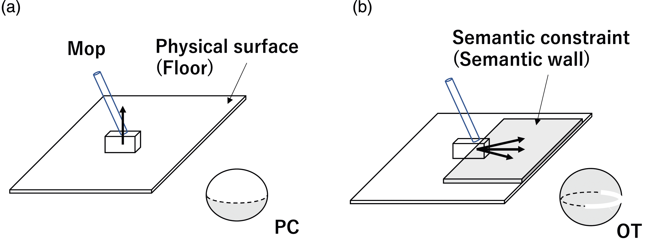
4.3. State transitions
Only a limited number of possible transitions occur physically. For the transitions of translation states under translation displacements, our previous paper found that out of 100 possible transitions with 10 starting states and 10 ending states under the original 10 states given by Kuhn–Tucker theory, only 13 transitions are actually feasible (Ikeuchi and Suehiro, 1994). This paper groups the original 10 translation states into 6 states according to their DoFs, so there are 36 possible interstate transitions, of which 8 transitions are actually feasible. These 8 interstate transitions plus 4 intrastate transitions give 12 state transitions. See Figure 8(a). State transition graphs. (a) Translation transition. (b) Rotation transition.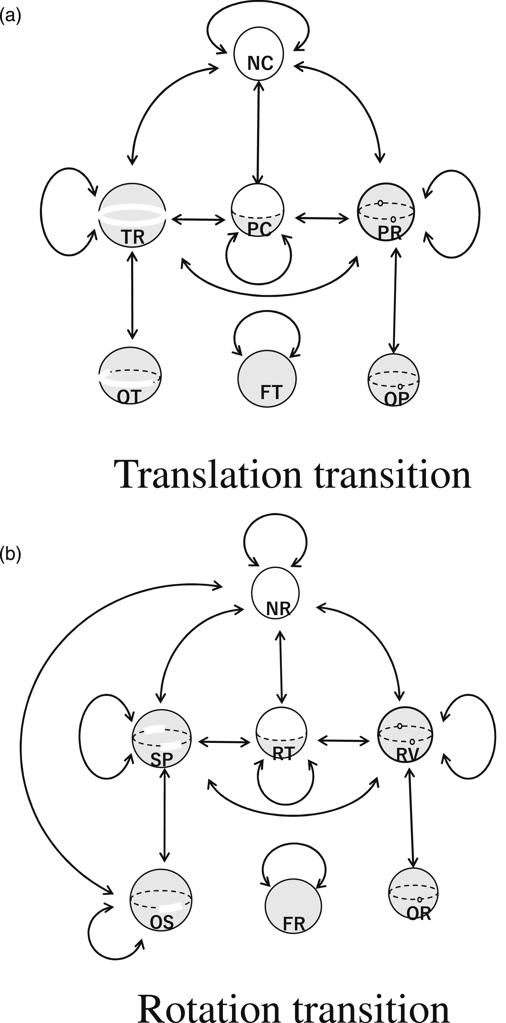
For the transitions of rotation states under rotation displacements that proceed with a similar analysis, the details are given in Appendix B, where nine interstate and three intrastate transitions are obtained. We can label the task groups comprising the found-state transitions on the graphs illustrated in Figure 8(b).
5. Task groups in household actions
In the previous section, we theoretically extracted the transitions that are physically possible. The purpose of the manipulation task can be defined as causing these transitions. Thus, these possible transitions define the necessary set of manipulation tasks to be performed. On the other hand, some transitions, such as PC-NC transitions, are instantaneous, and actions are observed that involve an infinitesimal PC-NC transition followed by a finite-length NC-NC move. Therefore, from the perspective of robot implementation, we consider a pair of transitions that occur continuously, such as PC-NC and NC-NC, but are almost impossible to visually separate, which we refer to as a task group, and consider them as building blocks of robot actions.
In the following, we investigate the extent to which task groups that can be defined theoretically actually occur in household actions. In other words, while the previous section defines the upper bound of the possible task set, this section aims to investigate how many of them actually need to be prepared as building blocks for service robots. To this end, we take two approaches: first, we analyze housekeeping actions directly from cooking videos and count up the task groups that occur; second, we analyze the captions of YouTube cooking videos and count up the task groups that occur.
The first approach utilizes videos of miso-soup and beef-stew production from the preparation stage to the serving stage recorded by one of our collaborators with a careful selection of camera positions to avoid possible occlusion of hand movements. We then segmented these videos into intervals surrounded by grasp-release pairs using LabanSuite (Ikeuchi et al., 2018), and described these intervals using the state changes in physical and/or semantic constraints.
The second approach is based on YouTube captioning. We collected 80 YouTube videos corresponding to cooking, carpet cleaning, floor cleaning, and furniture cleaning. Some of them were difficult to apply to our LabanSuite, due to blurred recordings of hand movements. Thus, we instead collected the video captions and extract verb-noun pairs. The actions associated with these verb-noun pairs provided state transitions.
Finally, we merged the first and second results into task groups. The extracted groups were classified into three categories: physical, semantic, and multistage. The physical class group considered only transitions due to physical constraints, while the semantic class group considered action objectives due to semantic constraints. Multi-level class groups can be decomposed into several multiple component groups defined using the previous two classes.
When numbering the physical class, some numbers were intentionally omitted so that groups between physical and semantic classes would correspond to each other. In addition, some state transitions predicted by the screw theory rarely occur in household actions; these were also omitted from the numbering. In the following discussion, physical, semantic, and multistage groups are abbreviated as PTG, STG, and MTG, respectively.
5.1. Physical class
5.1.1. PTG1: Relocation group
PTG1: Relocation task group.
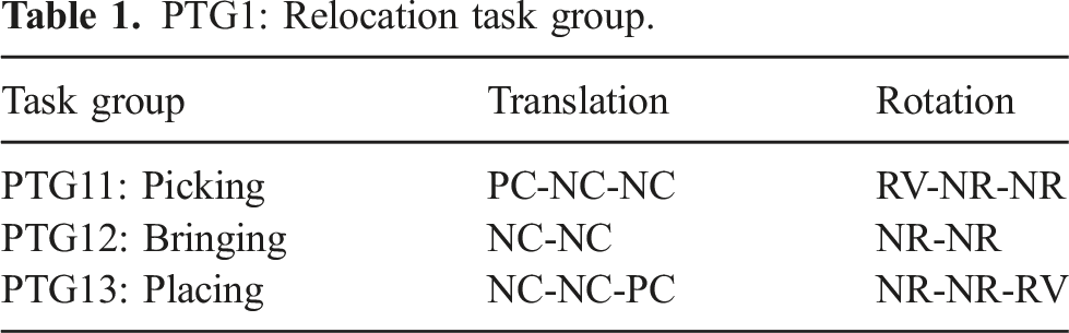
The PTG11: Picking task group incorporates lifting a target object (e.g., a box) from an environment (e.g., a table). For example, at the beginning, a box contacting the table surface can only be translated in an upward direction (PC state) and it can rotate around the surface normal of the table (RV state). Thus, the box state begins with (PC, RV). As the box breaks contact with its table environment with an infinitesimal action along the surface normal, it can then be translated in any direction (NC state) and can rotate about any axis (NR state). Thus, at the end of the infinitesimal action, the object state transitions to (NC, NR).
Theoretically, state transitions at infinitesimal displacements can be defined, but when observed as actual data, they will always be observed only if they are followed by a finite interval of displacement. Thus, pick (PTG11) task group is observed as a PC-NC infinitesimal transition, followed by a finite interval of NC, that is, PC-NC-NC in translation, and rotation states, RV-NR-NR. For this reason, a task group, not a task, is assigned to a single pick action.
The PTG12: Bringing task group moves the target object from one location in the air to another, also in the air. This group is often surrounded by Picking and Placing groups. However, in demonstrations such as the one described later, a series of PTG12 task groups can be used to represent multiple segments along a particular path to teach the robot that particular path to avoid obstacles.
The PTG13: Placing task group, which is an inverse of the previous Picking task group, places an object onto an environment surface. Initially, the object is in the air in an (NC, NR) state. Once the object contacts the environment surface after a finite interval of translation action, an infinitesimal transition causes the movable direction of the object to be restricted to an upward direction, and the rotation axis to be constrained along the surface normal: it is thus in the (PC, RV) state.
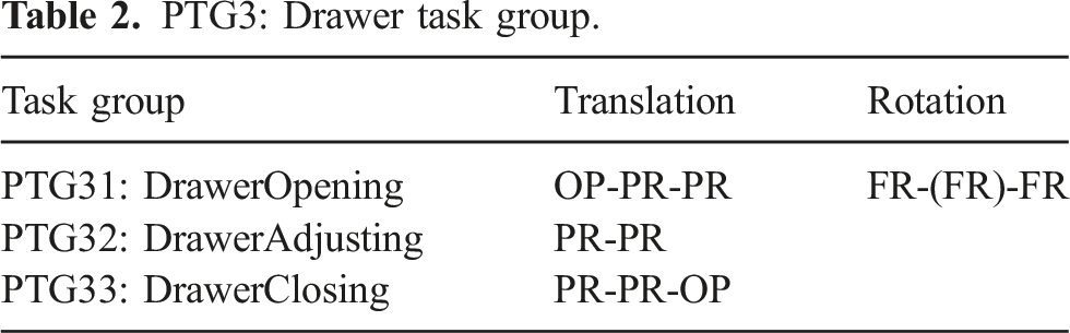
5.1.2. PTG3: Drawer task group
PTG3: Drawer task group.
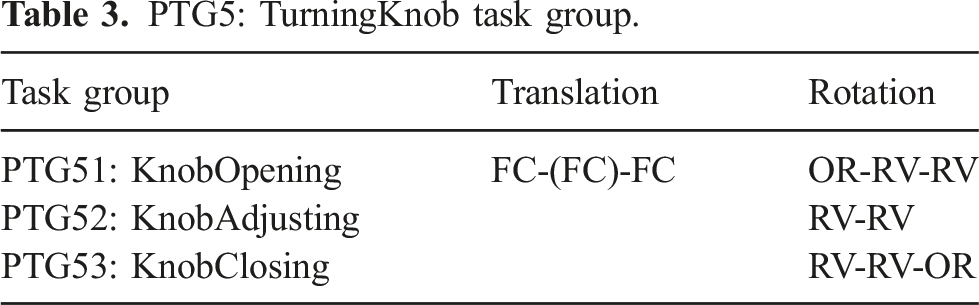
5.1.3. PTG5: TurningKnob task group
PTG5: TurningKnob task group.
5.2. Semantic class
Household actions require many semantic intuitions that cannot be expressed by physical constraints and are only obtained from semantic constraints given by common sense involved in performing household actions.
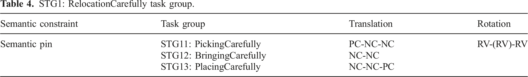
5.2.1. STG1: RelocationCarefully task group
Among the many household actions requiring semantic constraints that appeared in the data, the first patterns include picking up, bringing, or placing a cup containing a liquid. If we ignore whether the liquid is spilled or not, the cup can be freely rotated while being moved (in the NR rotation state). However, the common sense for moving such a cup to avoid spilling includes the common sense that the normal direction of the liquid surface should be aligned with the direction of gravity.
We refer to this semantic constraint of alignment as a semantic pin constraint; that is, we should not rotate the cup about the axis perpendicular to the direction of gravity as if there were an imaginary pin extending from the water surface. See Figure 9(a). This constraint is semantically represented as the RV rotation state instead of the NR. In terms of translational motions of the cup, there is no difference between carrying an empty cup and carrying a cup containing a liquid. Therefore, these state transitions can be summarized as shown in Table 4. Semantic pin and wall. (a) Semantic pin. (b) Semantic wall. (c) An example scene of STG12 in the cooking video. (d) An example scene of STG2 in the cooking video. STG1: RelocationCarefully task group.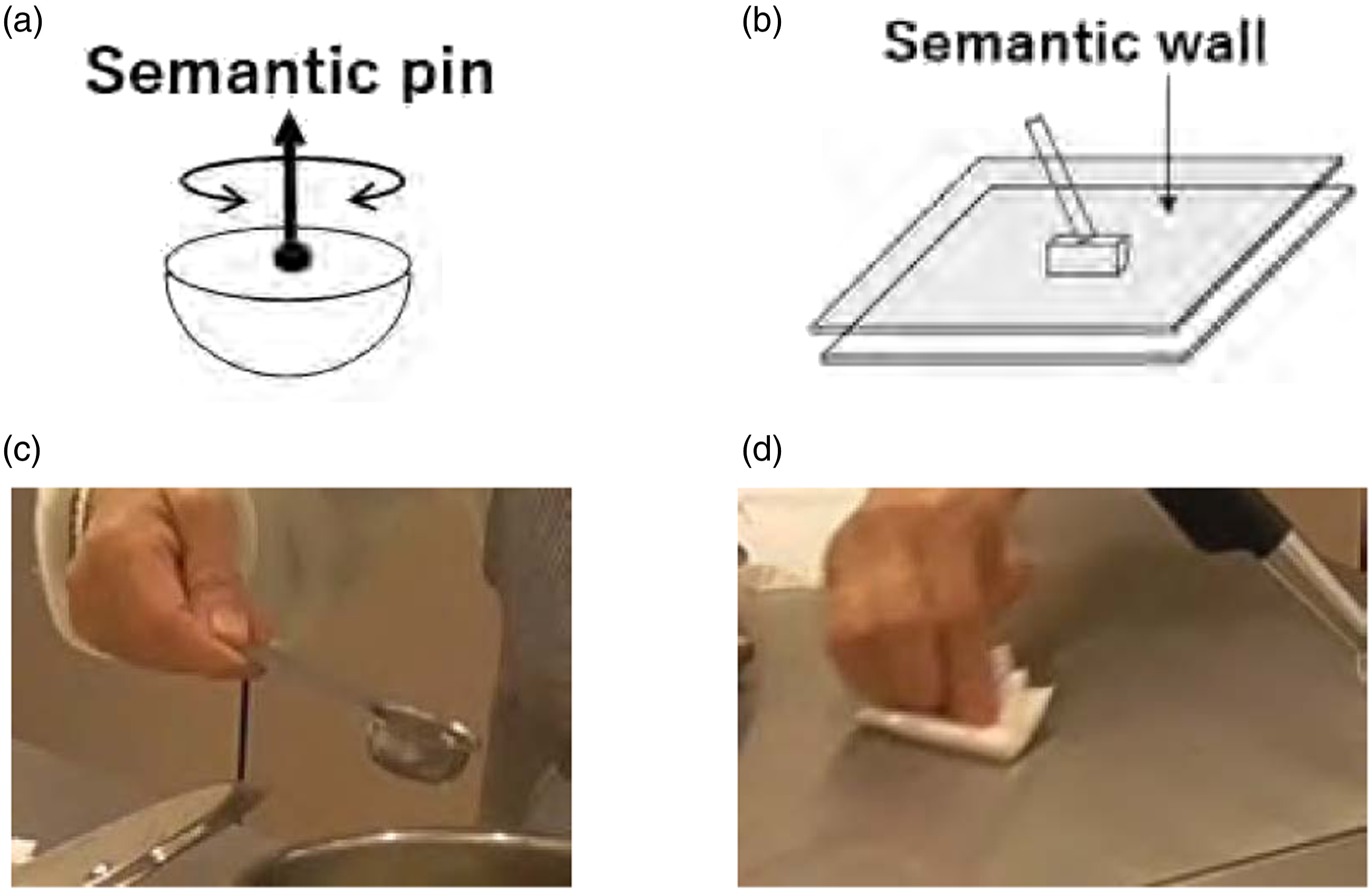
5.2.2. STG2: Wiping task group
This pattern involves the planar translation of a tool on the environment surface, such as a table or a window. Although the tool has a PC state in translation under physical constraints, the cleaning action cannot be achieved when the tool is detached from the environment surface. To avoid this detaching movement, we introduce a semantic wall parallel to the environment surface to represent the contact state TR instead of PC in the translation state. See Figure 9(b). To start/end the wipe action, the tool should move in one direction. Therefore, it should have an OT translation state at the start or end.
Regarding the rotation, small rotations around the surface normal of the environment are allowed as RV state for wiping a floor.
STG2 to STG6.
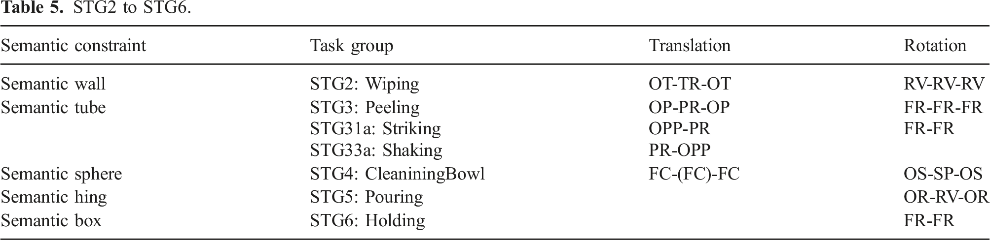
5.2.3. STG3: Peeling task group
In this pattern, a tool (e.g., a peeler) must perform a linear translation on the environment surface (e.g., a radish), which we refer to as the semantic tube constraint. Although the tool has a PC translation state under the physical constraint, the peeling action can only be achieved if the peeler moves along an imagery tube parallel to the radish surface; the state of the peeler can be described as the PR translation state. To start and finish the task, the peeler should move in one direction: the OP translation state. Rotations are not allowed during peeling; its rotation remains in the FR state. See Figure 10(a) and Table 5. Peeling task group. (a) In a Peeling action, the tool makes a linear translation along a semantic tube parallel to the environment surface. (b) In a Shaking action, an object stops abruptly after a linear translation to sprinkle the contents, as if hitting the bottom of the semantic tube. (c) An example scene of STG3 in the cooking video.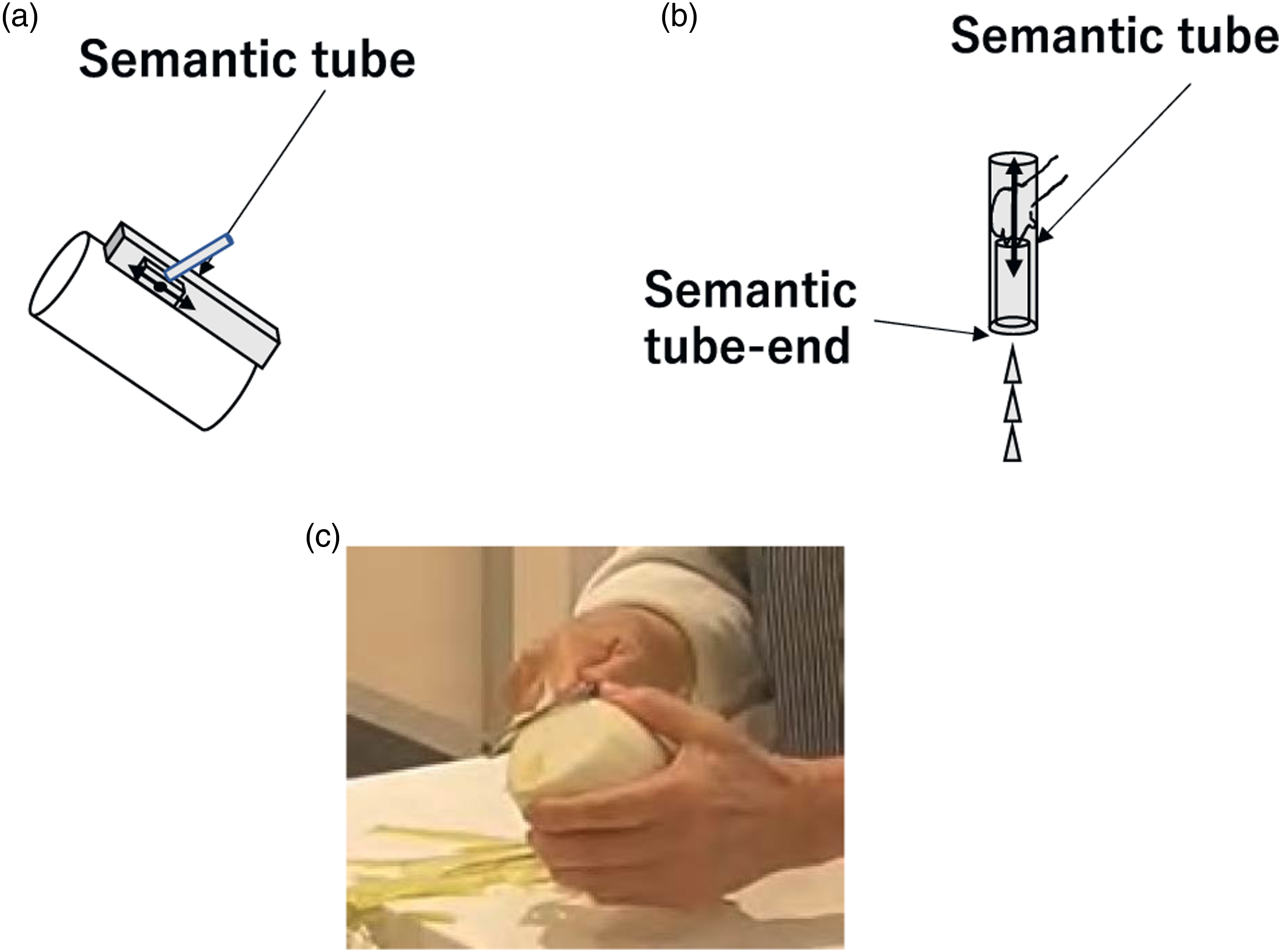
We found two minor variations of this STG3: Peeling group in the data used. The first variation, STG33a: Shaking occurred with actions of shaking ketchup out of a bottle. This begins with a linear motion in one direction as the OP state (STG31). It continues its translation in the PR state along the inside of an imaginary tube (STG32) and stops abruptly in the OP state as if hitting the bottom of the tube (STG33a). See Figure 10(b). To specify this abrupt stop, we note the state as OPP instead of OP. Thus, the state transition, STG33a can be specified as PR-OPP instead of PR-OP. Shaking action group was extracted from the scene of adding ketchup, adding Tabasco, or adding pepper to the food.
Similarly, the second variation, STG31a: Striking action, involves cracking the shell of an egg or hammering a nail, which starts abruptly as a linear motion (STG31a) and continues after cracking the shell or hammering the nail (STG32 and STG33). We can specify this state transition of STG31a as OPP-PR.
5.2.4. STG4: CleaningBowl task group
A spherical motion occurs when wiping the inner surface of a bowl or pot (i.e., SP rotation state). We refer to this as the Semantic sphere constraint. Because the center of rotation does not translate during this spherical rotation, the translation state is maintained as FC during this action.
The rotation state transition starts with wiping in one direction (i.e., the OS state). In the middle of the action, the wipe can rotate around two axes, thus it transitions to the SR state. Finally, the action ends in the OS state. This group is summarized as shown in the semantic sphere row in Table 5.
5.2.5. STG5: Pouring task group
In this pattern, a liquid or semi-liquid is poured from a container. Since the container is being held in the air, the physical condition does not impose any constraint on the translation and rotation of the container; it can move or rotate freely under physical constraints. For pouring, however, it is necessary to fix the flow outlet of the container in the FC translation state. The container must rotate around this flow outlet. We refer to this as the semantic hinge constraint, which requires the OR state to start pouring. To avoid overflowing, it also requires the OR state at the end. See Figure 11(a). Pouring group. (a) A pouring action rotates an object with respect to an imaginary rotation center due to the semantic hinge constraint. (b) A sprinkling action rotates an object to sprinkle the contents evenly over the environment based on a rotational motion with respect to the semantic hinge. (c) An example scene of STG5 in the cooking video. (d) Another example scene of STG5 in the cooking video.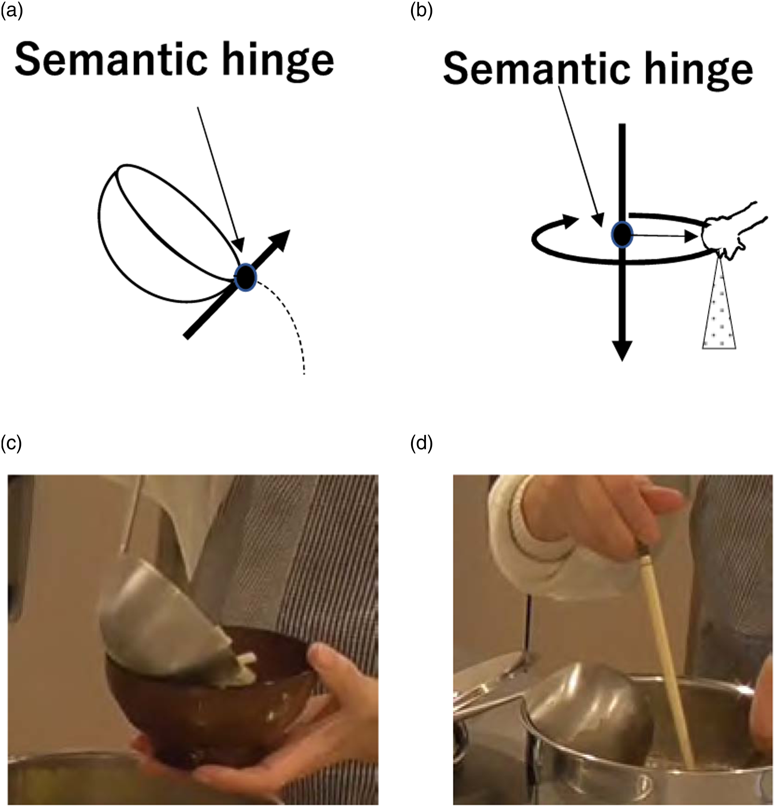
Another household action in this group that appeared in our data was a sprinkling action, in which a substance is sprinkled evenly from a container (or a hand) onto a surface. This action looks a bit different from the pouring action. However, this action can be considered as a pure rotational motion with respect to the center of the receiving area, as shown in Figure 11(b). During this action, the rotation center does not move in the FC translation state, and the rotation axis is aligned with the direction of gravity in the RV rotation state. To start the action, the rotation direction is one-way, and to stop, the rotation direction is again one-way.
The difference between sprinkling and pouring actions is the location of the rotation center, and the rotation center of a sprinkling action is outside of the convex hull of the hand or the tool, while the pouring action’s center is inside the convex hull. In terms of state transition, however, they belong to the same task group STG5. See Figure 11.
5.2.6. STG6: Holding task group
When cutting an object, such as a radish, one hand holds a knife and the other hand holds the radish for support. This supporting action, holding the radish, can be semantically specified as an FC translation and an FR rotation, referred to as the semantic box constraint. Thus, the state of the object remains FC in translation and FR in rotation, as if it were inside of an imaginary box. See Figure 12(b). Semantic sphere and semantic box.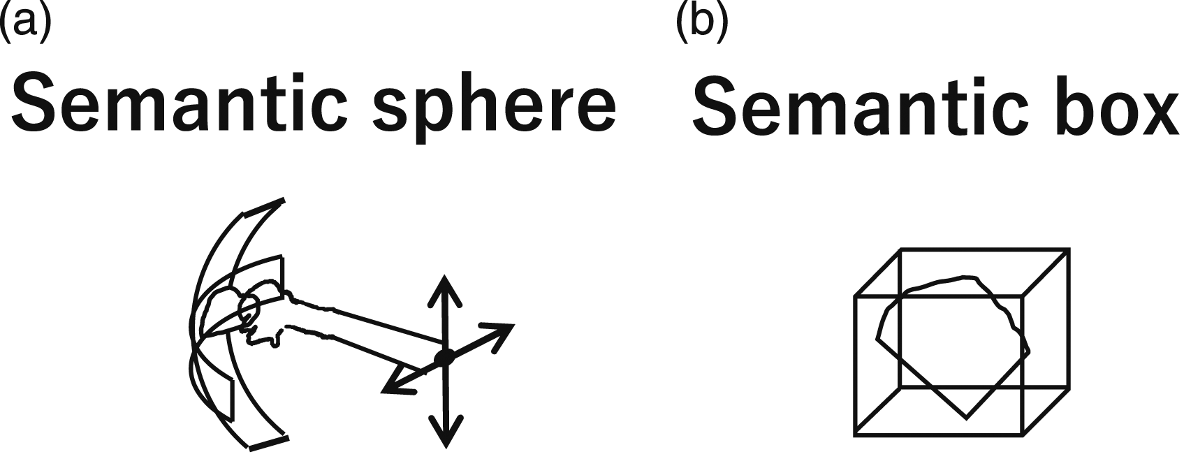
A similar holding action often occurred in the recordings used, such as when collecting running water with a bowl. In this action, the bowl can be rotated around the axis parallel to the direction of gravity while collecting the water. However, this was rarely found in the data, so we semantically classify these actions as having a FR rotation state. See Figure 12(a).
5.3. Multi-step class
Some household actions must be considered multi-step actions. We analyze such multi-step actions, and the multi-step task groups are abbreviated as MTG.
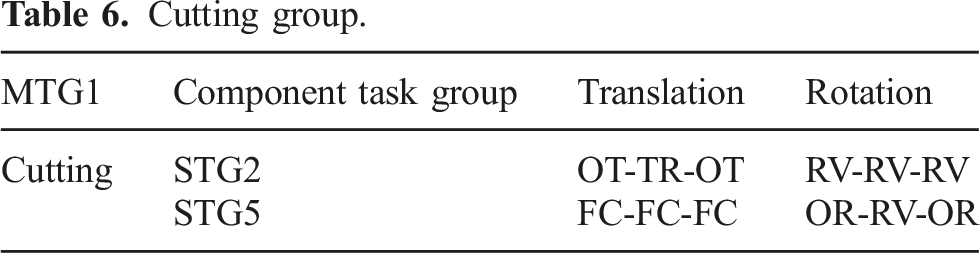
5.3.1. MTG1: Cutting task group
Actions found in our data, such as cutting a radish or a carrot, had the two-step action pattern. In the first step, the knife was translated between two walls in a certain direction until the corner of the knife hit the cutting board. Then, during the second step, the knife rotated around the contact point until the cutting edge of the knife was parallel to the cutting board. See Figure 13(a). Cutting and flipping.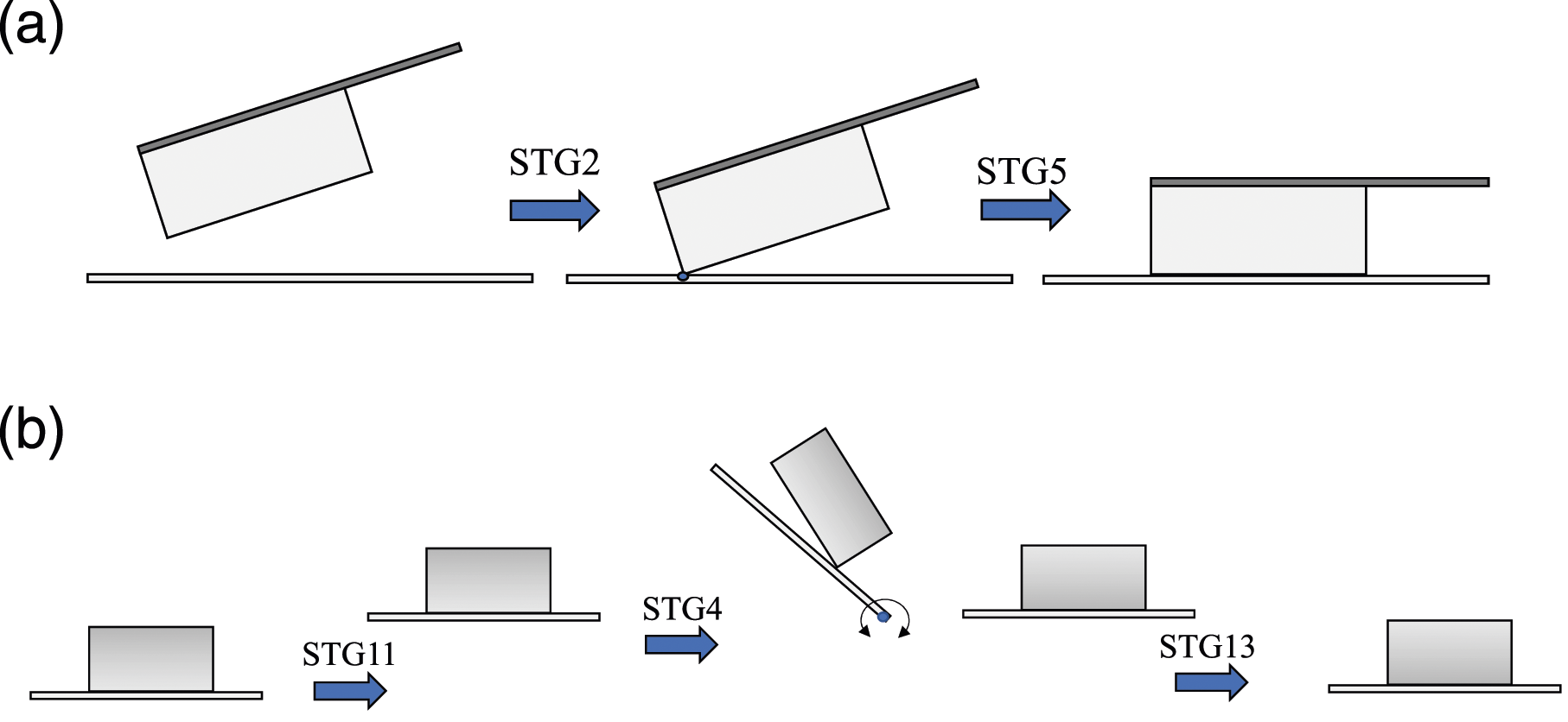
The first step starts from an OT translation state and then continues its translation motion to transition to the TR state; it finally ends its translation motion in an OT state. The rotation is considered to be a 1-dimensional (1D) rotation of the RV state, because the knife rotates with respect to the axis orthogonal to the knife plane. Thus, the first stage has the pattern of the STG2 task group.
Cutting group.
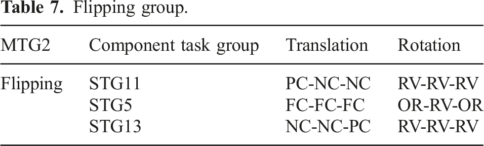
5.3.2. MTG2: Flipping task group
Flipping group.
5.4. Observed task groups and exceptional transition
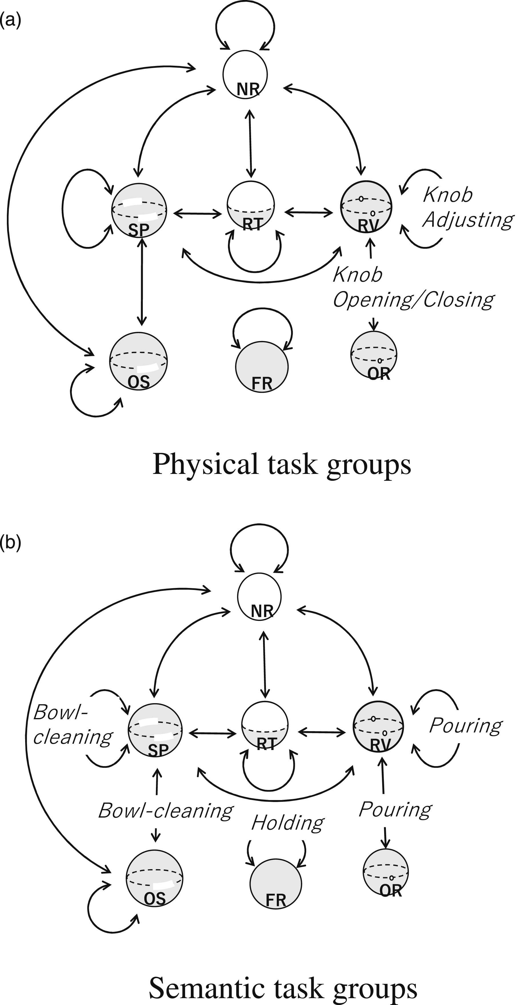
This sub-section will examine how many of the theoretically defined task groups are actually observed in the cooking video analysis and which are not. Figures 14 and 15 show the observed task groups superimposed on the theoretical transition graph for translation and rotation, respectively. Labeled arcs correspond to observed transitions, while unlabeled arcs represent transitions that are theoretically possible but did not actually occur. State transition graphs (translation) and corresponding household actions. (a) Physical task groups (b) Semantic task groups. State transition graphs (rotation) and corresponding household actions. (a) Physical task groups (b) Semantic task groups.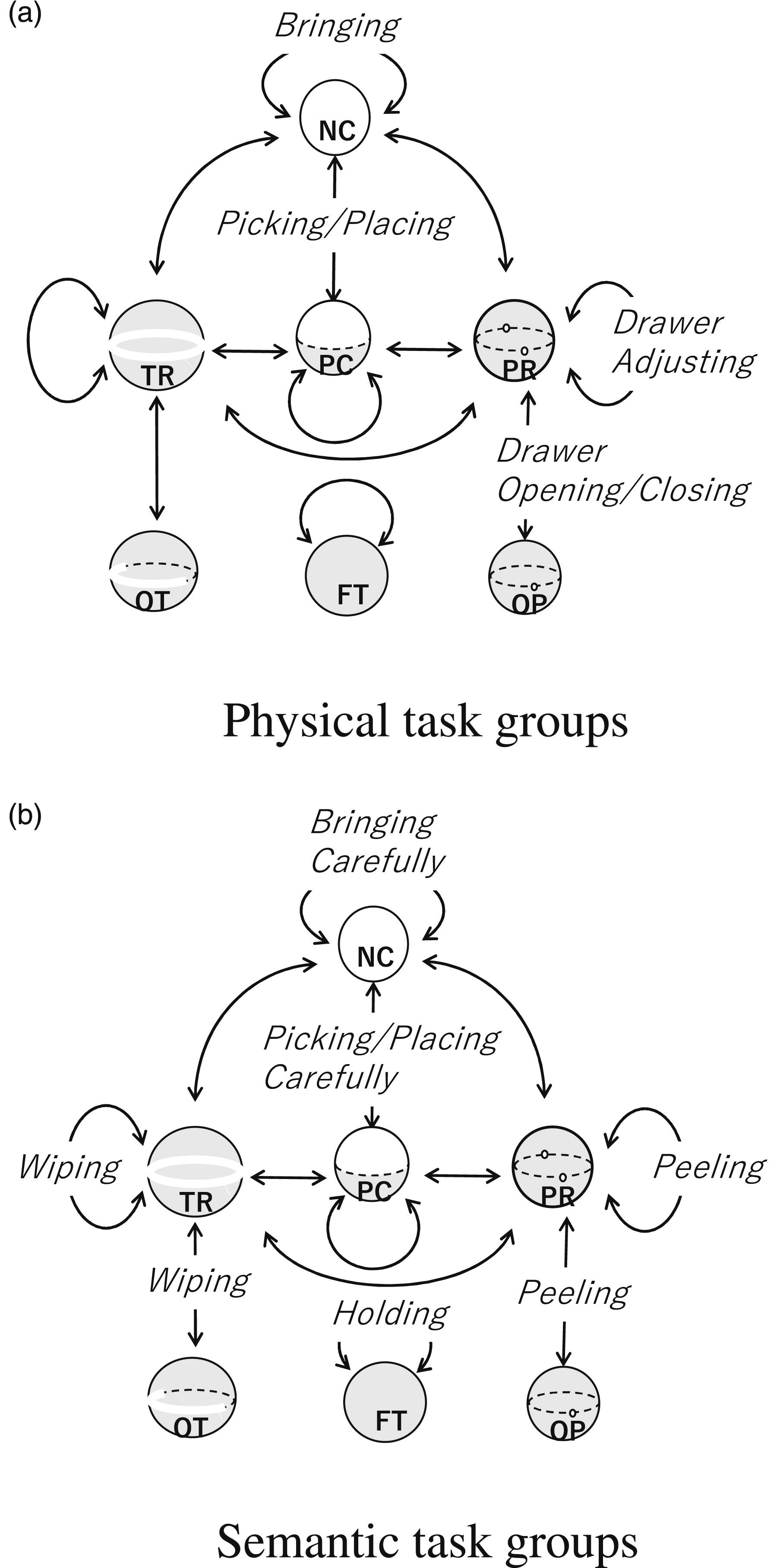
As can be seen from the graph, despite our best efforts, some transitions were not observed in the video. With respect to translations, these are NC-TR, NC-PR, PC-TR, PC-PR, and TR-PR transitions. To examine the reason why we do not observe, let us consider the NC-PR transition as an example. This transition corresponds to the case in Figure 16(a) where the drawer is initially fully pulled out (NC), but later pushed in (PR). However, it is much easier for a human to first position it at the entrance (PC), then to rotate it to the pushed-in position (PR) and to push in (PR) rather than suddenly going from NC to PR. For this reason, it would have been unlikely to find NC-PR in the videos. Exception cases. (a) NC-PR translation transition (b) NP-SP rotation transition.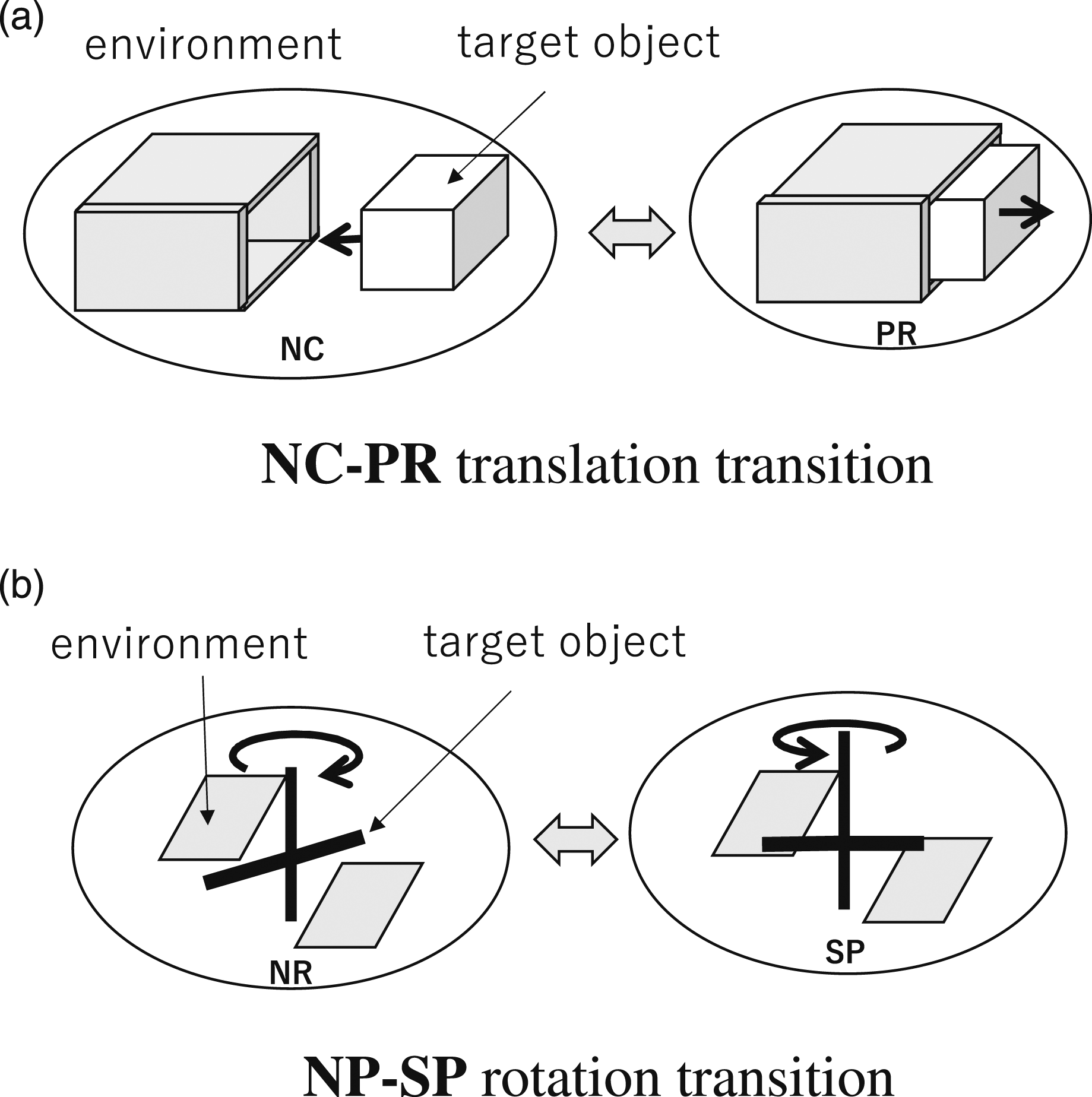
In the case of rotation, NR-OS, NR-SP, NR-RT, and NR-RV, the axis of rotation, which is originally not constrained at all, is suddenly constrained because of new surface contacts, as shown in the example in Figure 16(b). SP-RV, RT-SP, and RT-RV also have similar properties. These actions are also peculiar and difficult to do, and therefore could not have been observed in the videos.
In conclusion, the found task groups are sufficient to represent most of the standard household actions with physical and semantic constraints, and these can be prepared as building blocks for household service robots. Note, of course, that although any additional task groups can be added to the building blocks as needed, the upper bound is still held by the transition graph.
6. Task-group recognition from verbal instructions
In the previous sections, we found a set of task groups that take into account physical and semantic constraints and are capable of representing a sufficient set of household actions. To apply these task groups to robot teaching, a system must recognize the task groups from human demonstration.
Although most robot teaching research relies on hand trajectories (e.g., Argall et al., 2009; Billard et al., 2008), the hand trajectory is insufficient to distinguish whether a demonstration is PTG3, STG2, or PTG5, especially when the trajectory is very short. Meanwhile, the task groups are strongly related to the tool and environment involved in the task. We hypothesize that such relationships can be obtained at low cost using linguistic information such as verbal or textual instructions. To test this, we first collected a dataset of textual instructions, and we then trained a classification model using the dataset. Finally, we evaluated the performance of the model using cross-validation.
6.1. Textual instructions dataset
To prepare the textual instructions dataset, we first prepared a dataset of short videos labeled with the task groups, and then collected textual instructions for the short videos using a crowd-sourcing service (i.e., Amazon Mechanical Turk: AMT).
6.1.1. Preparation of short-video dataset
Since the task groups were obtained by analyzing cooking videos, we focused on representative actions required for cooking. We prepared the short-video dataset based on an existing dataset provided by Saudabayev et al. (2018), which include egocentric (first-person) RGB videos of people cooking breakfast. Egocentric videos were chosen to minimize the effect of the demonstrator’s self-occlusion on the annotation. To minimize the annotation effort, we used a subset of the original video dataset.
Examples of actions found in the video dataset and corresponding task groups.
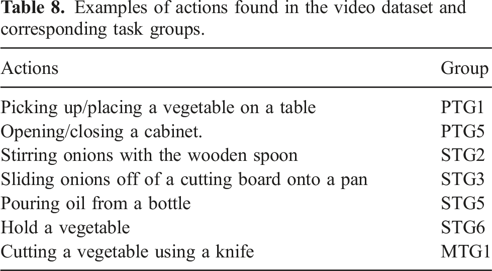
After annotation, a short-video dataset was created by segmenting the original video into each annotated task period. In the following experiment, we focused on the seven task groups (i.e., PTG1, PTG5, STG2, STG3, STG5, STG6, and MTG1) shown in Table 8 that were most frequently found in the videos. Figure 17 shows examples of the short videos, “Pouring oil from a bottle (STG5),” and “Cutting potatoes (MTG1).” Examples of actions by the right hand. (a) Pouring oil from a bottle (STG5: Pouring). (b) Cutting potatoes (MTG1: Cutting).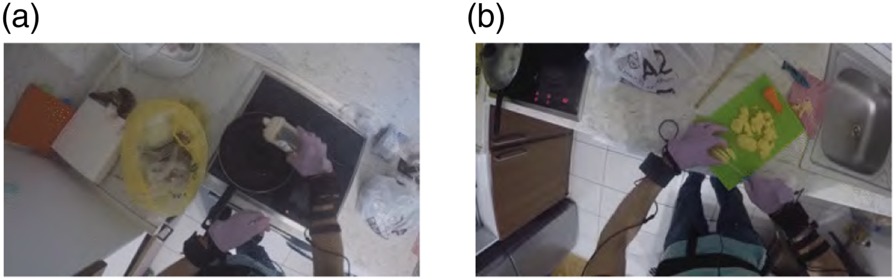
6.1.2. Collecting textual instructions using a crowd-sourcing service
93 AMT workers were invited to participate in the data collection. Each worker watched 10 short videos randomly selected from the short-video dataset and provided textual instructions for each. After each presentation, the workers were asked to “describe the action as if you were demonstrating it to someone in front of you.” As described, a video could contain both left-handed and right-handed tasks, depending on the situation. Therefore, the workers were clearly instructed to use their focus hand. To minimize confusion, the 10 videos were chosen to focus only on the left or right hand.
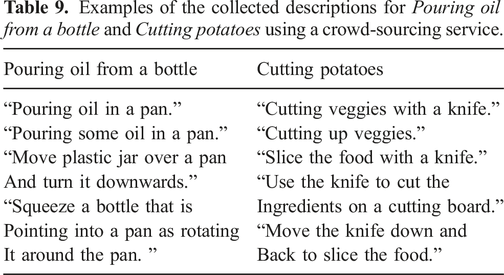
Examples of the collected descriptions for Pouring oil from a bottle and Cutting potatoes using a crowd-sourcing service.
6.2. Building a classification model of task groups
We trained a classification model that takes a sentence as input and outputs the task group of an action corresponding to the sentence.
First, each sentence was vectorized using the word2vec method of Mikolov et al. (2013). After rendering all letters lowercase, a vector representing a sentence, usent., was calculated using the following equation: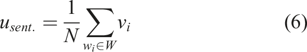
A random forest (RF) classifier (Breiman, 2001) was used to classify the vectorized sentences. This model provides a type of ensemble learning that can approximate any decision boundary regardless of the linearity of the boundary (Strobl et al., 2009). We used an RF method because we wanted to focus on the ability to classify sentences into task groups without assuming the shape of the classification function. The performance of the model was quantified by the cross-validation performance and the classification accuracy of each action group.
6.3. Results and discussions
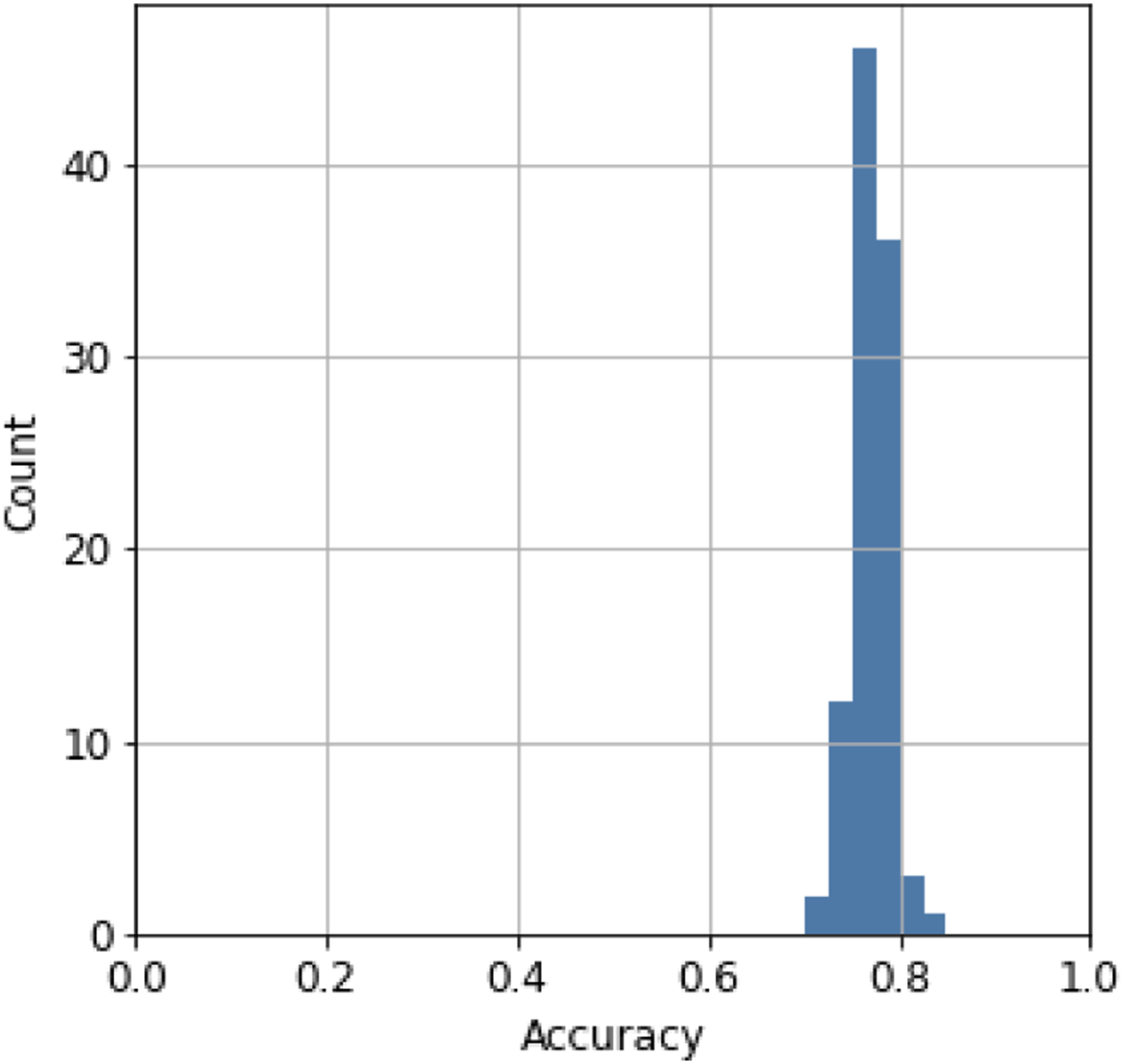
Figure 18 shows the confusion matrix of the prediction using 20% of the dataset for testing. The result suggests that the model can classify task groups, independent of PTG or STG, from textual instructions. We performed five-fold cross-validation 100 times (Figure 19) to validate the result. The performance of each cross-validation was calculated as the mean accuracy of the five validations. The average performance over the 100 trials was 77% (2.0% standard deviation), indicating that the model stably classified about 80% of the sentences in the dataset correctly. These results suggest that the task groups can be recognized from verbal instructions. Confusion matrix for recognizing task groups from verbal inputs. Values are normalized by the number of tested samples for each true class. Histogram of the accuracy of five-fold cross-validation conducted 100 times.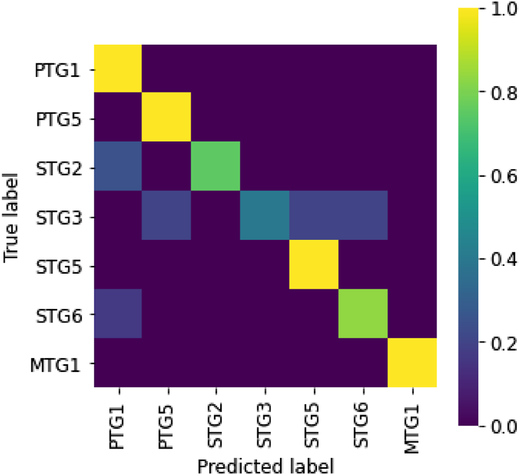
In the confusion matrix, the recognition error for STG3 is relatively high. A detailed database analysis revealed that STG3 (peeling) is confused with STG5 (pouring) to the sentence, “Move the food into the pod with the handle,” which was given by a crowd work to the video segment in which a spatula is sliding on a cutting board to relocate vegetables on the cutting board (STG3) into a pot. In other cases, STG3 (peeling) was confused with STG6 (holding) for the sentence, “Hold the food steady over the garbage can with the left hand and guide it along the knife held in the right,” which was given to the video segment in which a knife in the right hand is peeling a potato (STG3) held with the left hand over a garbage can. Although we encouraged the crowd workers to describe the right hand task when collecting the linguistic data, in the case of recognition failures, confusion is likely to occur due to the objects or verbs for left-hand sub tasks. Such errors can occur in other task groups in general, but the fact that STG3 was often paired with a left-hand movement due to the nature of the cooking operation, increases the confusion rate for STG3. Since we conducted this experiment, ChatGPT has recently been publicly available, which can greatly improve the performance (Wake et al., 2023).
In summary, this section has investigated the possibility of recognizing task groups from verbal instructions. Based on the hypothesis that semantic constraints can be recognized from linguistic information, we created a classification model to estimate task groups from textual instructions. As hypothesized, the model estimates task groups containing both physical and semantic classes with an accuracy of about 77%.
The results in the previous section show that task groups can be recognized by verbal or textual instructions. However, in order for a robot to execute the task groups, it is not sufficient to know only the task group. For example, the text “Hold a vegetable” is recognized as STG6, but it is not apparent from the text whether the vegetable is held in the air (in the case of peeling in STG3), or whether the vegetable is held on a cutting board (in the case of cutting a vegetable in MTG1). Second, texts such as “Pour oil” (STG5) are ambiguous in that the amount of oil to be poured is not specified; even adding the terms “pour a little” or “pour a lot” is subjective and lacks definitive information.
To understand the details of each task group, and to capture only the essence of a task group, we associate each task group with a task model. A task model is a framework, analogous to Minsky’s frame (Minsky, 1988), to recognize and collect detailed behavioral parameters, referred to as skill parameters, for performing each task group in order to transfer human skills to the robot.
The core idea of the task model is to determine which parts of the demonstration are important based on the physical and semantic constraints of each task group. Each task model has a set of predefined skill parameter entities called slots and a set of daemon functions to fill those slots. These slots are designed based on physical and semantic constraints. These parameter values are filled by observing the human demonstration, that is, by the daemon functions to invoke vision processing modules and then obtaining the values from those modules.
6.4. Task models for physical task groups
Figure 20 shows an example of a task model for representing the PTG11 task group. Note that PTG11 consists of PC-NC and NC-NC transitions. Since the first PC-NC is instantaneous and the parameters are identical to the second NC-NC transition, the series of state transitions is combined into a task group PTG11 and represented as a single task model PC(-NC)-NC which has the following slots: PTG11 task model.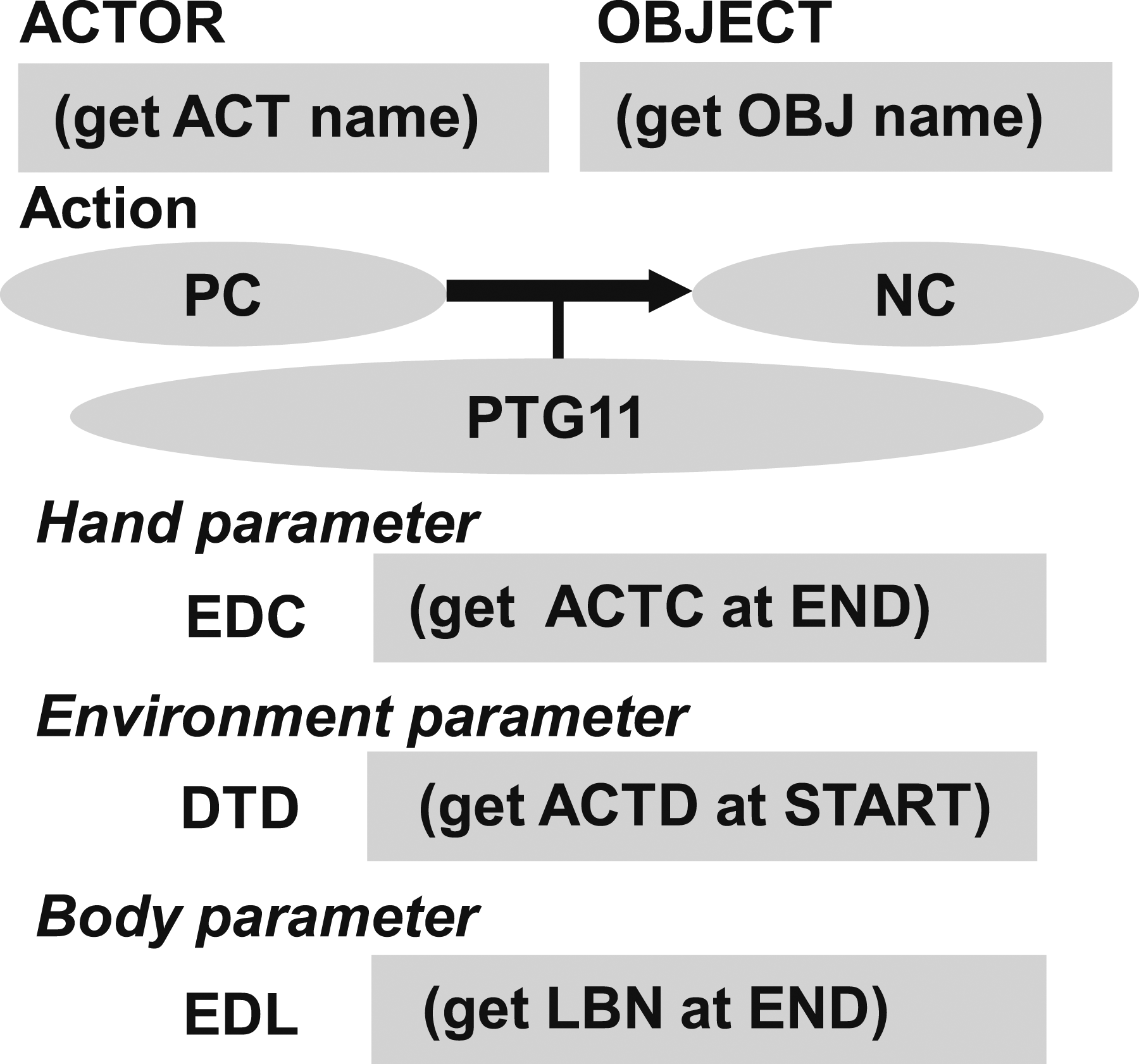
ACTOR—the hand used to manipulate the object, that is, left or right. OBJECT—the name of the target object to be manipulated. EDC (EnD-hand-Configuration hand parameter)—the position and orientation of the Actor at the end of the task group. DTD (DeTach Direction environment parameter)—the detach direction of the Object during the task group. EDL (EnD-Labanotation body parameter)—the human posture at the end of the task group, represented as discrete upper and lower arm pointing directions in Labanotation (Hutchinson-Guest, 1970).
Each slot in the task model has a specific daemon function to collect information its corresponding to that slot. Once the task group is recognized by the verbal instruction, the corresponding task model is instantiated and these daemon functions are activated to review the corresponding video segment and accumulate the values corresponding to each slot. In PTG11 task model, the following daemon functions are employed: (get ACT name)—obtains the Actor name (left hand or right hand), which is usually inherited from the previous task model because in the case of PTG11, another task such as the grasp task is always executed immediately before this task group. (get OBJ name)—obtains the Object name, which is also inherited from the previous task model. (get ACTC at END)—obtains the hand orientation at the end of the task. (get ACTD at START)—obtains the moving direction of the hand at the start of the task. (get LBN at END)—obtains the Labanotation at the end of the task.
Hand parameters, environment parameters, and body parameters are slot categories common to all task models. The hand parameter is a parameter that primarily describes the relationship of the hand to the object, such as the approach direction during grasping and the position of the hand with respect to the object-centered coordinate system. The environment parameter describes the relationship of the object motion with respect to the environment coordinate system and is derived from the physical and semantic constraints.
The “EDC (EnD Configuration of the hand)” hand parameter describes the hand configuration at the end of the task group. Namely, it specifies how much to lift the object with respect to the object centered coordinate system at the start of the task group. Assuming that the robot executing the task model has joint state feedback and an accurate model of the robot, the robot is able to calculate its current state at the beginning of PTG11, so only the end parameters “EDC” need to be obtained from the demonstration by the daemon function, (get ACTC at END), which obtains the actor’s configuration, the hand position and orientation, at the end.
The “DTD (DeTach Direction)” environment parameter describes the detach direction in the PTG11 task group. PTG11 breaks the contact relationship from the PC state to the NC state with a detach motion. To do so, the object must be lifted from the environment in the correct direction (e.g., perpendicular to the environment), and this motion direction is stored in the “DTD” slot by the deamon function, (get ACTD at START), from the demonstrated hand motion. Note that the TSS module that executes the task model, which is not described in detail in this paper, is designed based on the object motion so that different manipulators can be used by simply replacing the IK, effectively using the role-division algorithm (Sasabuchi et al., 2020, 2023; Ikeuchi et al., 2023).
The “EDL (EnD Labanotation)” body parameter describes the human posture at the end of the task group. The body parameters constrain the configurations of the robot when solving the 6D pose, especially when the robot has redundant degrees of freedom or a mobile base as explained by Sasabuchi et al. (2020) and Ikeuchi et al. (2023). It has been shown by the works that without the body parameters, a robot may succeed in performing a single task group (state transition), but fail to perform a series of task groups due to choosing an inappropriate configuration or base positioning that does not connect with a subsequent task group.
For the body parameter, we need a representation method to describe approximate postures. The difference between human and robot mechanisms makes it difficult to achieve exactly the same postures by taking exactly the same joint angles and joint positions at each sampling time. Our approximate imitation does not require such precise representations. Rather, it is necessary to capture the essence of these postures. For this approximation, we will use Labanotation (Hutchinson-Guest, 1970), described in the next sub-section.
All other physical task groups can be represented as task models in a similar manner as shown in Figure 21(a)-(c). Physical task models and grasp task models. (a) PTG1 task models include Picking, Bringing, and Placing task groups, and most of the slots are the same except that the daemon function (get ACTD) in PTG11 obtains the detaching direction (DTD) at the start of the task and (get ACTD) in PTG13 obtains the attaching direction (ATD) at the end of the task. (b) In PTG3 task models, the pushing or pulling direction is obtained by the daemon function (get AXIS) and stored in the AXIS slot. The detaching (DTD) and attaching (ATD) directions are also obtained in the same way as PTG1. (d) PTG5 task models have the AXIS slot, to store the rotation axis. (d) Grasp task models has the GTP slot to store the grasp type demonstrated. The grasp recognition is performed by the daemon function described by Wake et al. (2021b). The approach (APD) and departure (DPD) directions are also obtained, by the (get ACTD) daemon, at the end and the start of the task, respectively.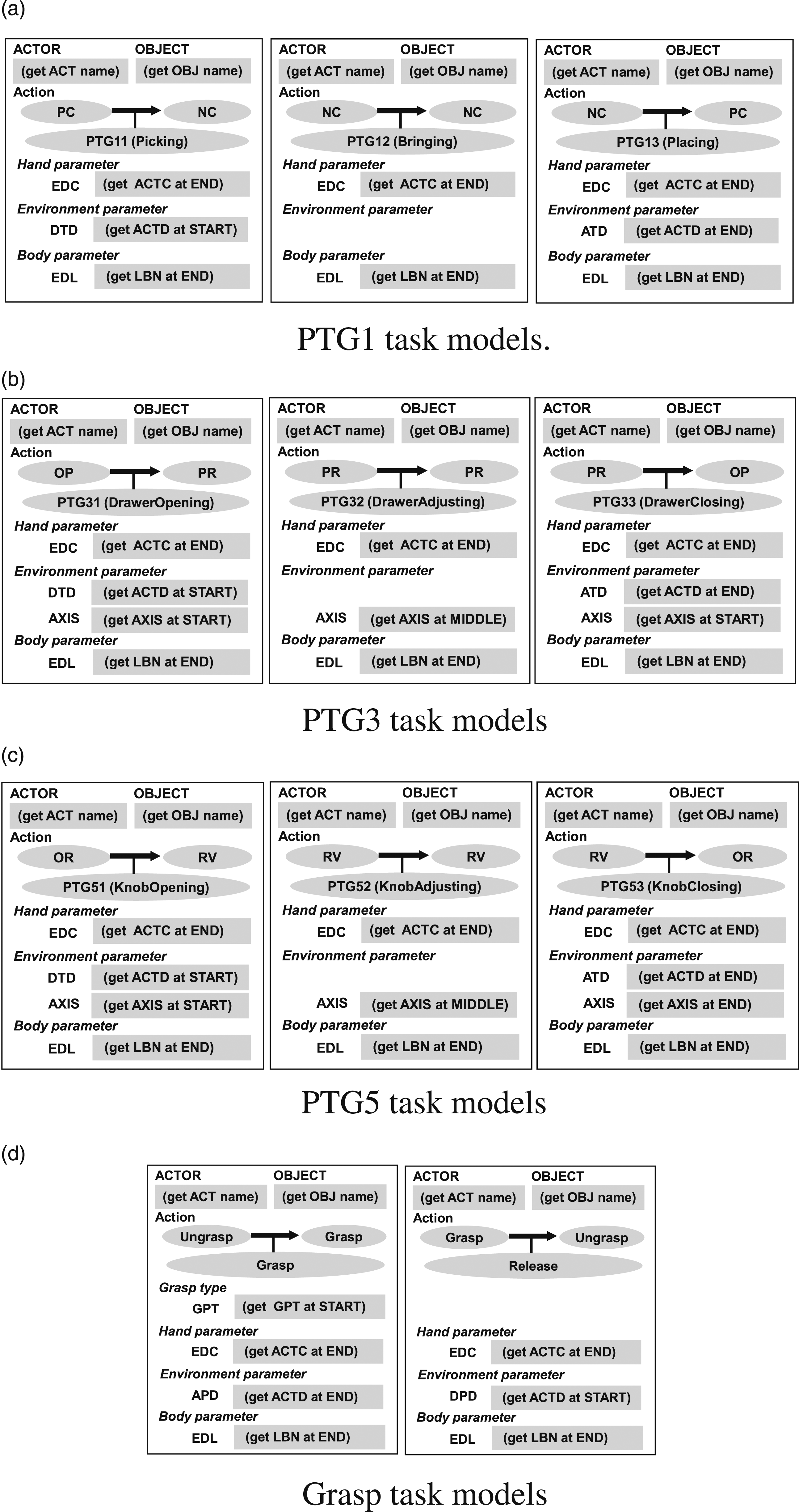
One issue in the demonstration-based approach is the difference in situation between the demonstration and the execution (e.g., the position of the target object). However, once an object is grasped, the object-hand relationship does not change between all task groups in the Grasp-Manipulation-Release (GMR) interval (which is the main scope of this paper) until it is released. Namely, the current object position can be calculated from the robot configuration. In addition, although there are some differences in the situation between the demonstration and execution, these differences are small, so we assume that directional values such as detach direction and axis direction can be reusable to the execution from the demonstration.
Although not in the scope of this paper, we have also designed Grasp and Release task models (Wake et al., 2021a; Ikeuchi et al., 2023) as shown in Figure 21(d). Note that apart from the demonstration time discussion here, an additional object localization daemon is also designed to account for differences in the position of the object at runtime and demonstration (Saito et al., 2022).
6.5. Labanotation and body posture
Labanotation (Hutchinson-Guest, 1970), a dance notation method developed in the dance community, is employed as a method that captures the essence of human behavior for LfO. The robot cannot imitate the human demonstration exactly as it is, due to kinematic and dynamic differences. Thus, when describing human demonstrations, it is necessary to record only their essence. The relationship between dance performances and Labanotation scores is similar to the relationship between music performances and music scores. Just as a piece of music can be performed from a music score, a piece of dance can be performed from a Labanotation score; just as a music score can be obtained from listening to a piece of music, a Labanotation score can be obtained from watching a piece of dance. More importantly, from the same Labanotation score, each dancer, with different heights and arm lengths, performs a piece of dance that appears the same to the observer. In other words, the Labanotation score is considered to capture the essence of the dance for the observer.
Labanotation consists of temporal and spatial digitization. Figure 22 shows a Labanotation score. In a music score, time flows from left to right, whereas in a Labanotation score, time flows from bottom to top. When humans look at a series of movements, they do not see a continuous movement, but rather focus on postures at certain points in time (mainly at short stops), and, then, interpolate them to understand a continuous movement. Labanotation follows this digitization in the time domain, that is, each symbol in the score represents a posture at each brief stop. Labanotation.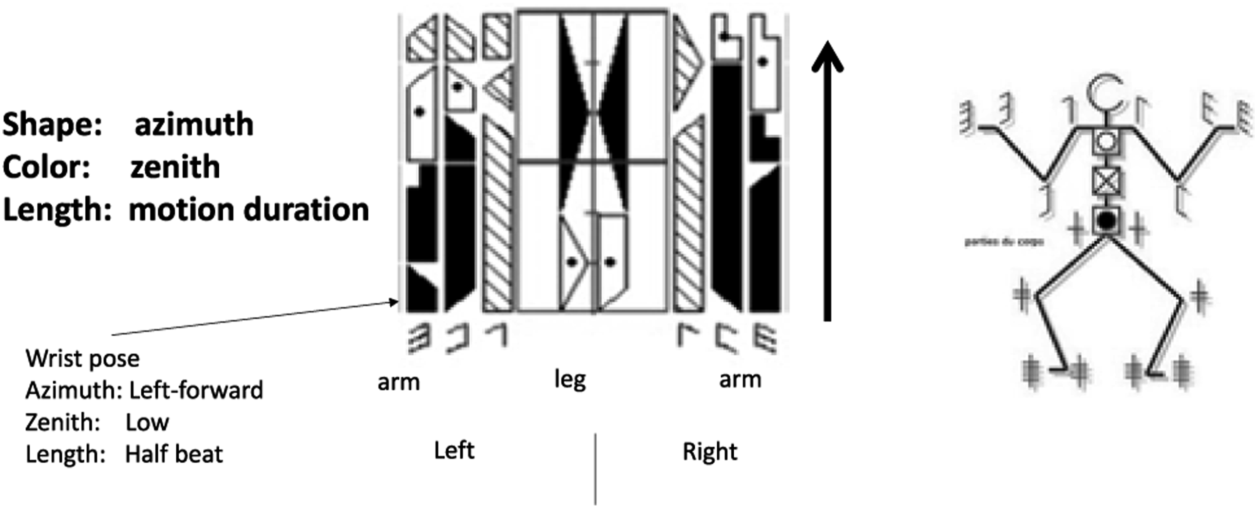
Each column of the Labanotation is used to represent the postures of one human part, such as an arm or an elbow. The length of each symbol represents the time it takes to move from the previous posture to that posture. The shorter the symbol, the faster the person moves the part; the longer the symbol, the slower the person moves the part.
The spatial digitization of the Labanotation consists of 27 directions. The spatial directions are divided into zenith and azimuth directions with respect to the human body, as shown in Figure 23(a). For the zenith direction, in addition to the zenith (Place, Normal) and the nadir (Place, Low), there are three levels of digitization: high, normal, and low, as shown in Figure 23(b). Each of the three levels is depicted by a black, shaded, or white texture of a symbol. The three zenith levels are further divided into eight horizontal directions, including forward/backward, left/right, and so on as shown in Figure 23(c). Adding the zenith, center, and nadir, 27 directions consist of the spatial digitization of the Labanotation, as shown in Figure 23(d). For example, the horizontal right direction is thus represented as Right, Normal. Although the digitization of the eight azimuth directions and the five zenith directions seems somewhat coarse, it is consistent with Miller’s theory of human memory capacity (Miller, 1956), which is probably why the dance community has represented directions with this granularity. Spatial digitization in Labanotation. (a) Azimuth and zenith direction with respect to the body. (b) Three levels in the zenith direction. (c) Eight horizontal directions in the azimuth direction. (d) 27 spatial directions.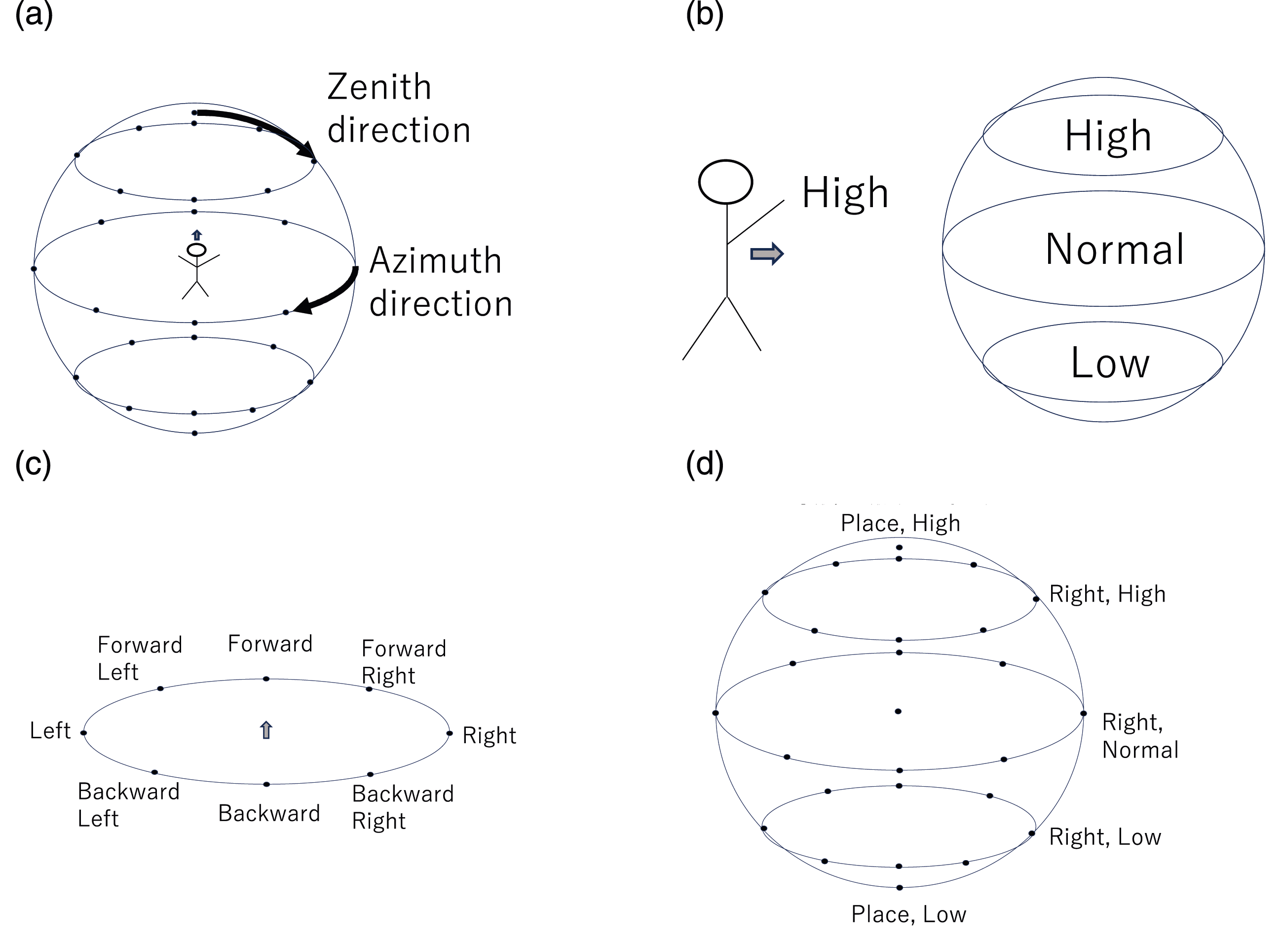
LabanSuite (Ikeuchi et al., 2018) has been developed to obtain a Labanotation score from a human movement sequence. The current LabanSuite has 2D and 3D versions: the 3D version uses a bone tracker from kinetic input, while the 2D version uses a bone tracker based on OpenPose (Cao et al., 2017) and lifting (Rayat Imtiaz Hossain and Little, 2017) from video input. Both versions extract short stops from the bone motion sequence based on the Labanotation rule and digitize postures at the granularity of 8 azimuth and 5 zenith directions according to the Labanotation rule. In this system, the 3D version with a Kinect sensor is used.
6.6. Task models for semantic task groups
A task model representation of the STG11 semantic task group is depicted in Figure 24; it has an extra slot, PinD, compared to PTG11. This slot stores the semantic pin direction derived from the semantic constraint, which is usually the gravity direction. STG11 task model has the PinD slot to contain the semantic pin direction, which is usually the gravity direction. The other slots are the same as PTG11 task model.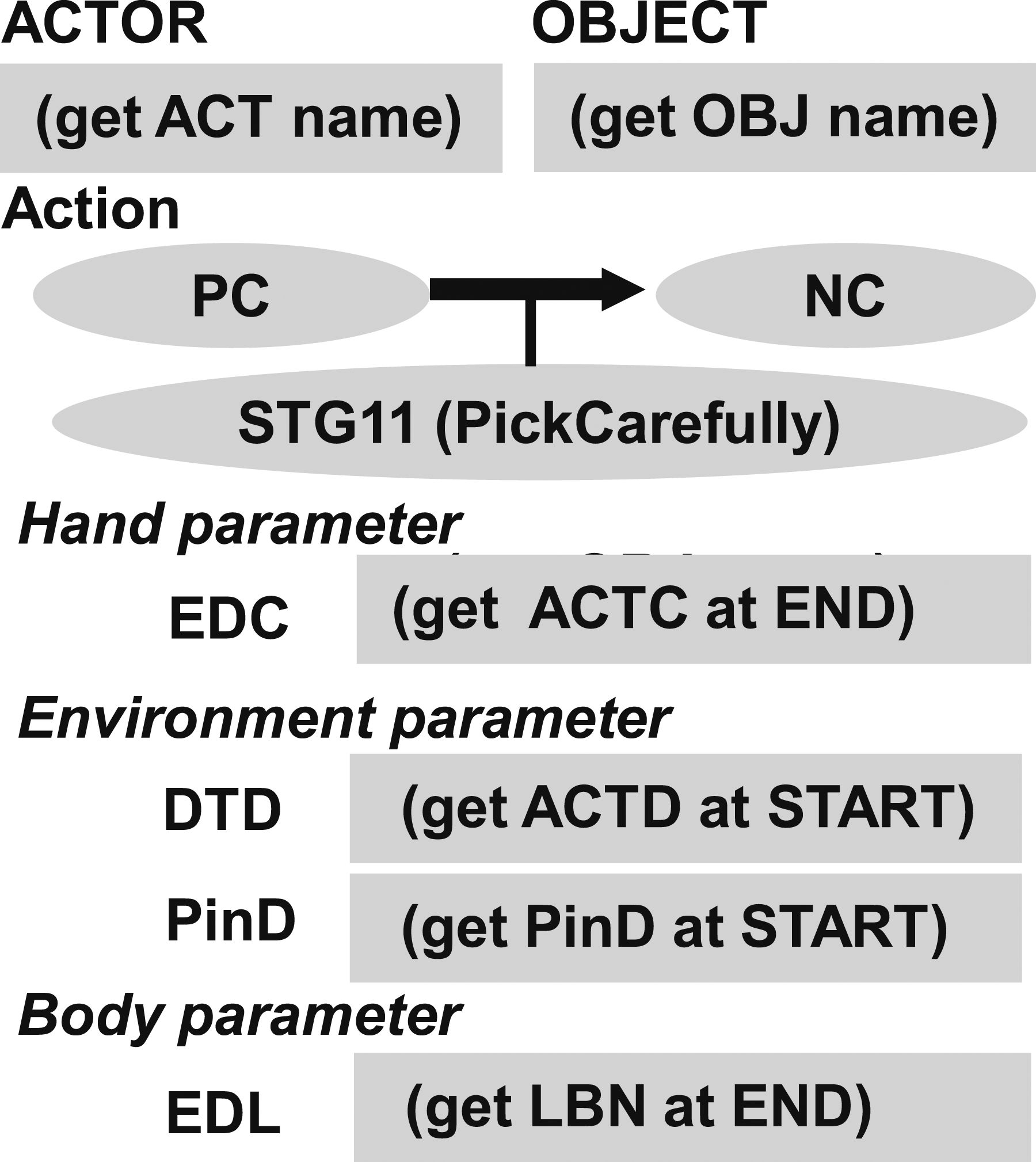
As in the previous example of STG11, the semantic task groups are also represented similarly as the task models of the physical task models (See Figure 25). This is not a surprise as both physical and semantic task groups come from the same contact state analysis. Semantic task models. (a) STG1 task models have the PinD slot to store the semantic pin directions. (b) STG2 (Wiping) and STG3 (Peeling) task models have semantic wall (WallD) and semantic tube (TubeD) directions, respectively. The ENV slot indicates with respect to which environment object the semantic constraint occurs. For example, in the case of wiping a table, the sponge to be the OBJ name and the table to be the ENV name. (c) STG31a (Striking) and STG33a (Shaking) models have the same structure but are defined as different task models because they have different runtime controllers. (d) STG4 task model has the center of rotation (CTR) slot to specify the location of the semantic sphere center and STG5 task model has the AXIS slot to specify the axis location of the semantic hing.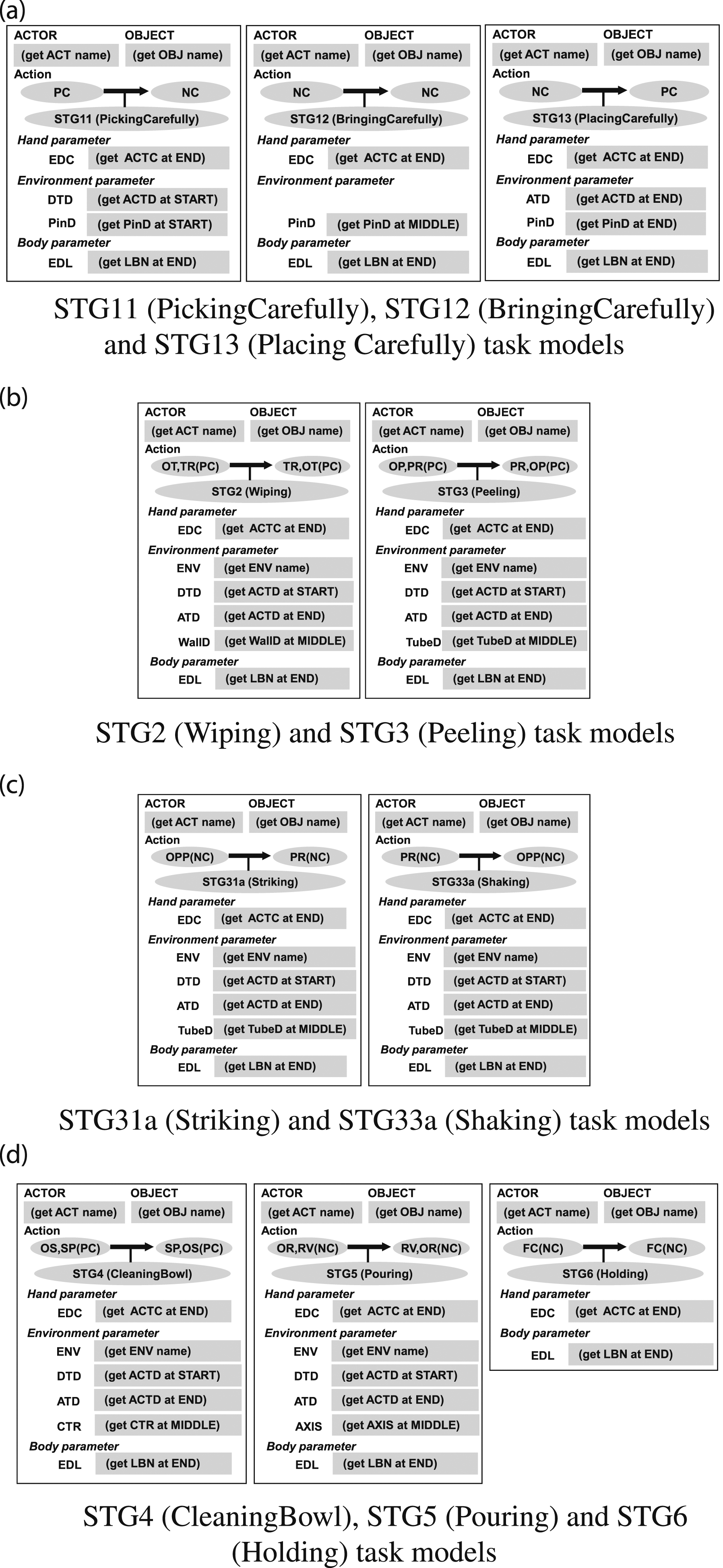
One difference, however, is that the state boundaries of the semantic task group, except for STG11 and STG13, are virtual boundaries and therefore do not generate physical drag forces like the boundaries of the physical task group. For example, in the physical task group of PTG33, when a door closes, a reaction force is generated from the wall. This generation of drag force can be used to train skills in reinforcement learning (Takamatsu et al., 2022). In other words, compliance control is possible. On the other hand, at the end of a wipe STG23 task, no reaction force is generated because it is a virtual boundary. Therefore the end condition is performed by position control; since the end condition for STG22 is also given by position control, there is no difference in control between STG22 and STG23. The same argument can be made for STG21 and STG22. For other semantic tasks, STGX1 and STGX3 can also be considered the same as the start and end parameters of the STGX2 task model. Therefore, STGX1, 2, and 3 are all represented as a single STGX task model for design simplification.
7. Task model in a real system
This section illustrates how the task models designed in the previous section work in the LfO system using actual demonstrations. The raw input to the system is a sequence of third-person RGB-D images captured by the Kinect 5 and audio signals recorded by a wireless microphone. The skeletal sequence obtained from the RGB-D images is then run through LabanSuite 6 to obtain keyframes and Labanotation (Ikeuchi et al., 2018). In parallel, the ego noise reduction filter (Wake et al., 2019) and the cloud speech recognition service 7 are sequentially applied to the speech signal to obtain transcribed instructions, from which a set of task groups is obtained through the language parser. The DP-based matching module makes the mapping between task groups and segments of RGBD image (Yanaokura et al., 2022). These results are cached in the system memory for later used by daemon functions.
A task model sequence is instantiated from the set of task groups obtained. First, the templates of the corresponding task models are ordered. Then, at each slot of task models, the corresponding daemon function either invokes a vision/language processing module or obtains parameters directly by reading from the system memory. Each vision processing daemon takes as input a particular segment of RGB-D images; the language processing daemon takes as input the transcribed texts.
For simplicity, the following experiments assume a single arm demonstration which begins and ends with the Grasp and Release tasks. All task groups surrounded by the Grasp and Release will be verbally stated with one task group per sentence (e.g., “Pick up the pitcher. Pour into the cup. Return the pitcher.”). We will assume that all physical task groups are either PTGX1 or PTGX3, that is, objects are not floating in the air, doors are not half-open, and so on. We will also assume that all semantic task groups except STG1 are assigned to a single task model STGX, that is, we will not distinguish between STGX1, 2, and 3 because they are all represented by the same task model (as explained in the previous section). Note that in this experiment, we made a slight modification to classify physical task groups as PTGX1 and PTGX3 instead of PTGX. This was easily achieved by relabeling sentences containing the word “pick” as PTG11 and sentences containing “place” as PTG13, “open” as PTG51, “close” as PTG53, and so forth.
7.1. PTG1: Pick-place demo
Figure 26 shows an end-to-end demonstration that primarily uses the PTG1 task models. First, the system receives the verbal instruction, “pick up a red cup” and “place it on the shelf,” and understands that the corresponding task models are PTG11 and PTG13 task models. This paper assumes that the task sequence is punctuated by grasping and releasing tasks and the model sequence is determined to consist of Grasp, PTG11, PTG13, and Release task models. Task models instantiated from the “Pick-place demo” image sequence. (a) Input scene, energy function for keyframe detection, and Labanotation obtained from LabanSuite. Only the upper and lower right arms are shown. (b) Instantiated task models with slot values collected by the daemon functions from video-rereview. (c) Example scene of the robot performing the same task.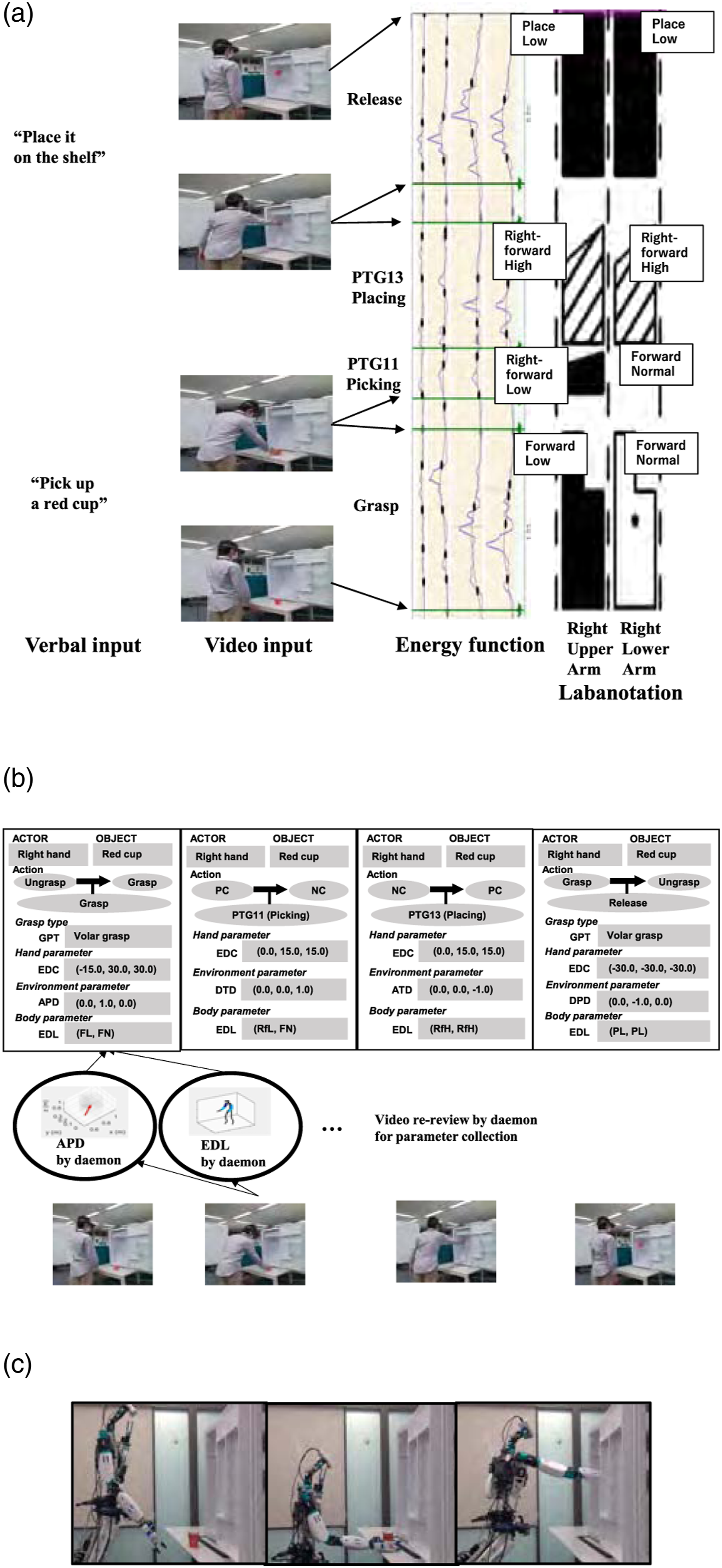
In parallel, the sequence of human skeletal poses during the demonstration is segmented by the keyframes detected by LabanSuite as shown in Figure 26(a), where the third column shows the energy curves used by LabanSuite for the keyframe detection. To conform the bottom-top notation method of Labanotation, the energy function is plotted so that the vertical axis is the time axis, with elapsing from bottom to top. A keyframe is defined as the moment when a body part stops. Here, the energy curves in LabanSuite represent the squares of the angular velocities of each body part, left-right upper arm and left-right lower arm, and the minima of the curve correspond to the keyframes at which some part(s) briefly stop (Ikeuchi et al., 2018).
Corresponding to the keyframes, the detected arm pointing directions (body parameters) are obtained, shown as Labanotation symbols in the fourth column of Figure 26(a). In this experiment, only the right arm was recorded, so there are two columns, and the postures at each keyframe of the upper and lower arm are represented as Labanotation symbols. The Labanotation indicates the final posture of the segment. For example, in the bottom two symbols, the black polygon in the left column (the upper arm column) indicates that the upper arm points the forward in azimuth angle and downward in zenith, and the white polygon in the right column (the lower arm column) indicates that the lower arm points forward in azimuth and toward the middle in zenith. This pose was taken at the end of the grasp task and immediately before the picking task. The gap between two black polygons indicates that there was a rather long pause between the grasp and the picking actions, which was intentionally inserted by the demonstrator. There is no symbol in the section of the lower-arm column corresponding to the Picking task due to the Labanotation convention of omitting the symbol for the same direction as in the previous section. The third textured symbols indicate the upper arm and the lower arm both to point right forward direction in the azimuth angle and up in the zenith angle to perform the placing task. These symbols are stored in the system memory and are retrieved by the task model daemon functions.
As shown in Figure 26(a), the four sections obtained from this analysis are assigned to the previous task model sequence in order, that is, Grasp, PTG11, PTG13, and Release, and the daemon functions in each task model analyze the hand postures in each section, and the corresponding values are incorporated into the task models as shown in Figure 26(b). For example, the approach direction (APD) of the Grasp task model is obtained from the last hand movement in the grasp section, and the body parameter (EDL) is obtained from the Labanotation at the section. For simplicity, this paper assumes a one-to-one correspondence between the task models from the verbal input and the segments from LabanSuite. We have also developed a DP method to deal with the problem of over- or under-segmentation issue (Yanaokura et al., 2022). In addition, a multimodal user interface is also prepared to allow the demonstrator to check the recognition results and correct any errors in order to prevent robot malfunctions resulting from task misrecognition due to verbal recognition or segmentation errors, details of which will be left for another paper (Ikeuchi et al., 2023; Wake et al., 2022).
Figure 26(c) shows the execution of the series of the instantiated (with the obtained slot values) task models by a humanoid robot. Each task model has a corresponding robot skill (Takamatsu et al., 2022). Each skill computes the end-effector trajectory to perform the task. In particular, the grasp skill also contains a daemon function for object recognition to capture the difference between the demonstration and the execution (Saito et al., 2022). The hand trajectory just before the grasp is computed from the object position by this vision module and the approach direction (APD) in the task model. The hand position at the end of the grasp is inherited as the hand position at the beginning of the PTG11 pick task. The hand trajectory at the start of the PTG11 task is generated from the position and the detach direction (DCD) in the task model. The hand position at the end of the PTG11 is given by the EDC in the task model.
Each skill iteratively calculates the next hand position by following the trajectory calculated from these positions and, if a skill requires, such as Place (PTG13) or Door-opening (PTG51), taking force feedback into account. Using the postures of the tasks specified by the Labanotation (EDL) as constraints, the inverse kinematics is solved to satisfy the hand position. Since each task model specifies only the hand position, different robots can perform the same task models by simply exchanging the inverse kinematics routine. Note here that we assume that modern humanoids have a degree of redundancy and that the hand and arm movements can be computed independently. For more details, see Ikeuchi et al., 2023; Sasabuchi et al., 2020; Takamatsu et al., 2022.
In this demo, for simplicity for speech analysis, we assume that all physical task groups are either PTGX1 or PTGX3, that is, the end point of PTG11 task is considered as the start point of PTG13 task. However, with a slight modification of the verbal and demo input, intermediate routes can be inserted. By deliberately stopping at a point that the demonstrator considers important, the system recognizes it as the break point of the previous task (Ikeuchi et al., 2023; Wake et al., 2022). For example, in the case of moving an object from the bottom shelf to the top shelf without collision, by stopping twice between the end of PTG11 and the beginning of PTG13, the system can insert three PTG12 (bring) tasks; PTG11 (pick), PTG12 (bring to the outside of the shelf), PTG12 (bring to the upward), PTG12 (bring to the inside of the shelf), and PTG13 (place). In other words, the demonstrator makes the path plan and teaches that path to the robot. Note that the robot does not follow the human’s path exactly, but only the points that the demonstrator considers important for collision avoidance, and for the rest of the path, the robot can take an easy one. See the corresponding videos in the service-robot manipulation section of our website 8 .
7.2. PTG5: Open-fridge demo
Figure 27 shows the result of obtaining parameters with the PTG5 task group. The verbal instruction includes only one sentence “open the fridge door” and therefore the system recognized that the demonstration involved a PTG51 and a grasp and release at the start and end. In this example, the segment, PTG51, is oversegmented into two segments, which are stitched together into a single segment using the DP method (Yanaokura et al., 2022). PTG51 task model instantiated in the open-fridge image sequence.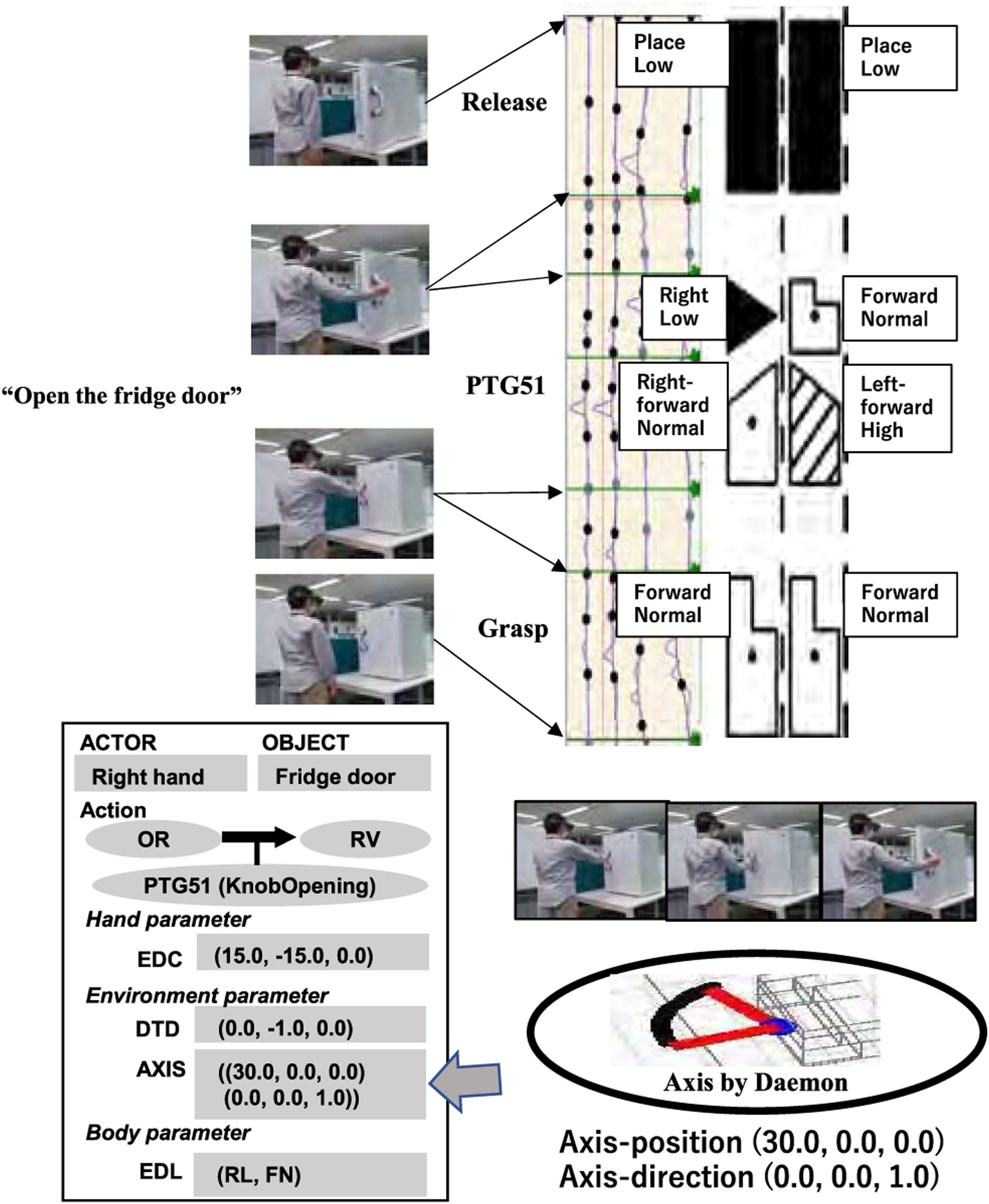
The PTG51 task model has the axis information (AXIS) slot with the (get AXIS) daemon. Generally, the hand trajectories observed in the teaching mode are noisy. However, by fitting a task-specific trajectory pattern based on the task model (e.g., a circular trajectory given by PTG51), an accurate parameter can be obtained, as shown in Figure 27 by the daemon function. Here, the axis information consisting of the direction and the position is represented with respect to the coordinate system attached to the part of the object grasped (i.e., the fridge door handle).
7.3. STG2: Wipe-table demo
Figure 28 shows the task model instantiated from the “wipe the table” demonstration. The recognized task sequence was grasp-STG2-release and the segments were similarly processed as the other tasks. Generally, a wiping action includes multiple wiping motions. A series of wiping motions is recognized and a series of task models are generated. Each STG2 task model, like the other task models, has the EDC hand slot, EDL body slot, DTD detach direction slot, and ATD attach direction slot. The ENV environment slot, a specific one to STG2, indicates the environment object to be wiped, which has the value “Table” collected by the daemon function (get ENV) from the verbal instruction. Another task-specific WallD slot specifies the direction of the semantic constraint. In this case, the opposite direction of the table surface is obtained and stored by the daemon function, (get WallD). STG2 task model instantiated in the wipe-table image sequence.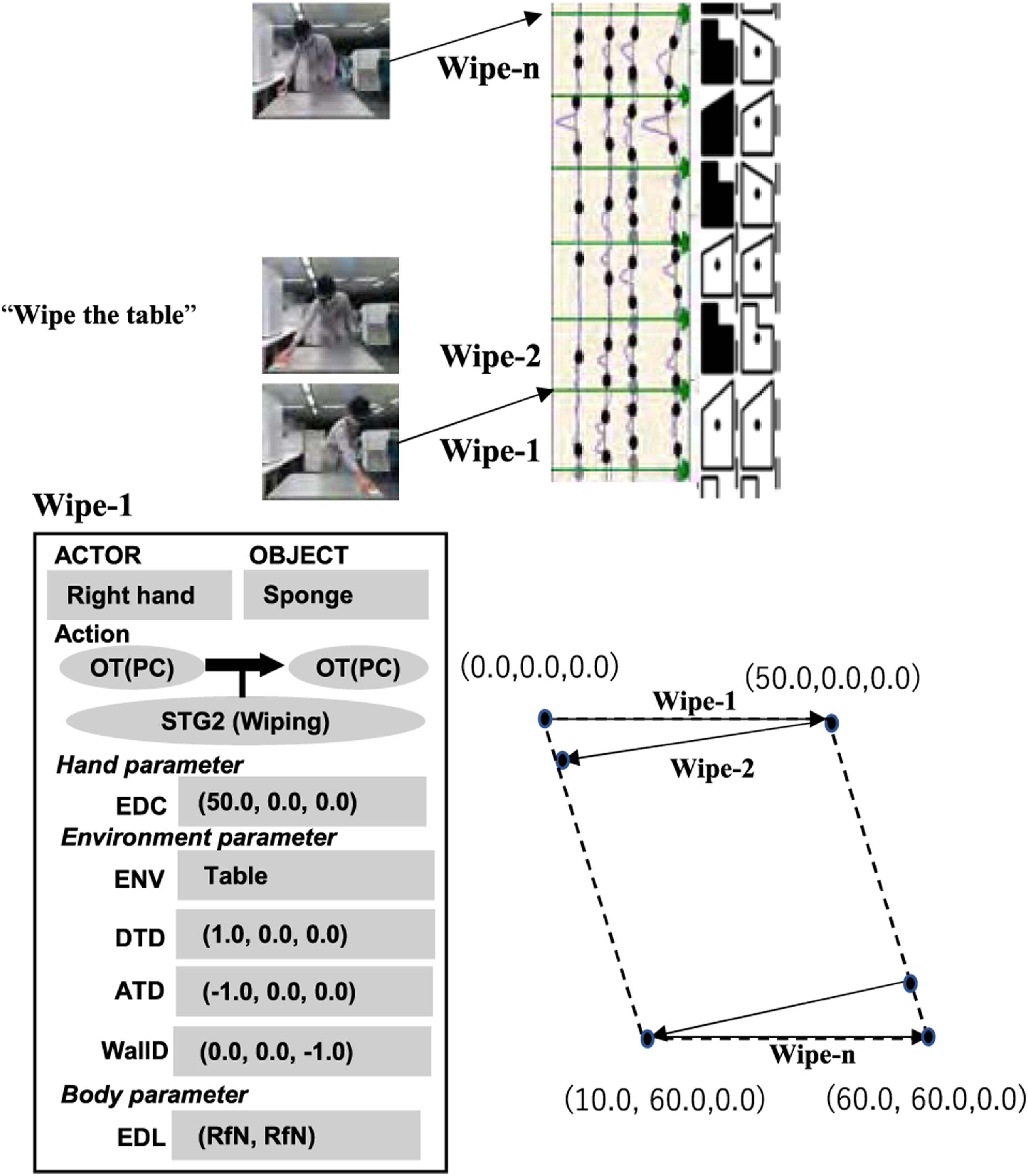
The current implementation simply follows straight lines given by the human demonstration. However, in other practical applications, it is necessary to modify the robot strategy according to some visually defined goals, such as to clean only dirty places. Although we have not implemented such applications, one way to enhance the current system is to obtain such goals from vision and then run some “visual goal planning daemons” assigned for each goal. Another future direction would be to define a global task model in which these fine STG2s are grouped together as a candidate area, and within the candidate area, would perform wiping tasks with the visual goals.
7.4. Pour-to-cup demo
Figure 29 shows the result of the STG5 demonstration. From the speech and the classifier, the recognized task sequence was grasp-STG11-STG5-STG13-release. The STG1 Pin-D slot is set to the direction of gravity (as this is the constraint defined for this task group). The segment boundary between STG1 and STG5 given by the DP method may be an error. Currently we are dealing with this by re-adjusting it with an STG1 region detector daemon that model-fits the pitcher and tracks its orientation (i.e., the segments where the object’s orientation does not change from the gravity direction by a certain threshold, are labeled as STG1.) Then, from the remaining segments, the daemon function invoked by the STG5 AXIS slot determines the rotation axis based on the pitcher movements. STG5 task model instantiated in the pour-to-cup image sequence.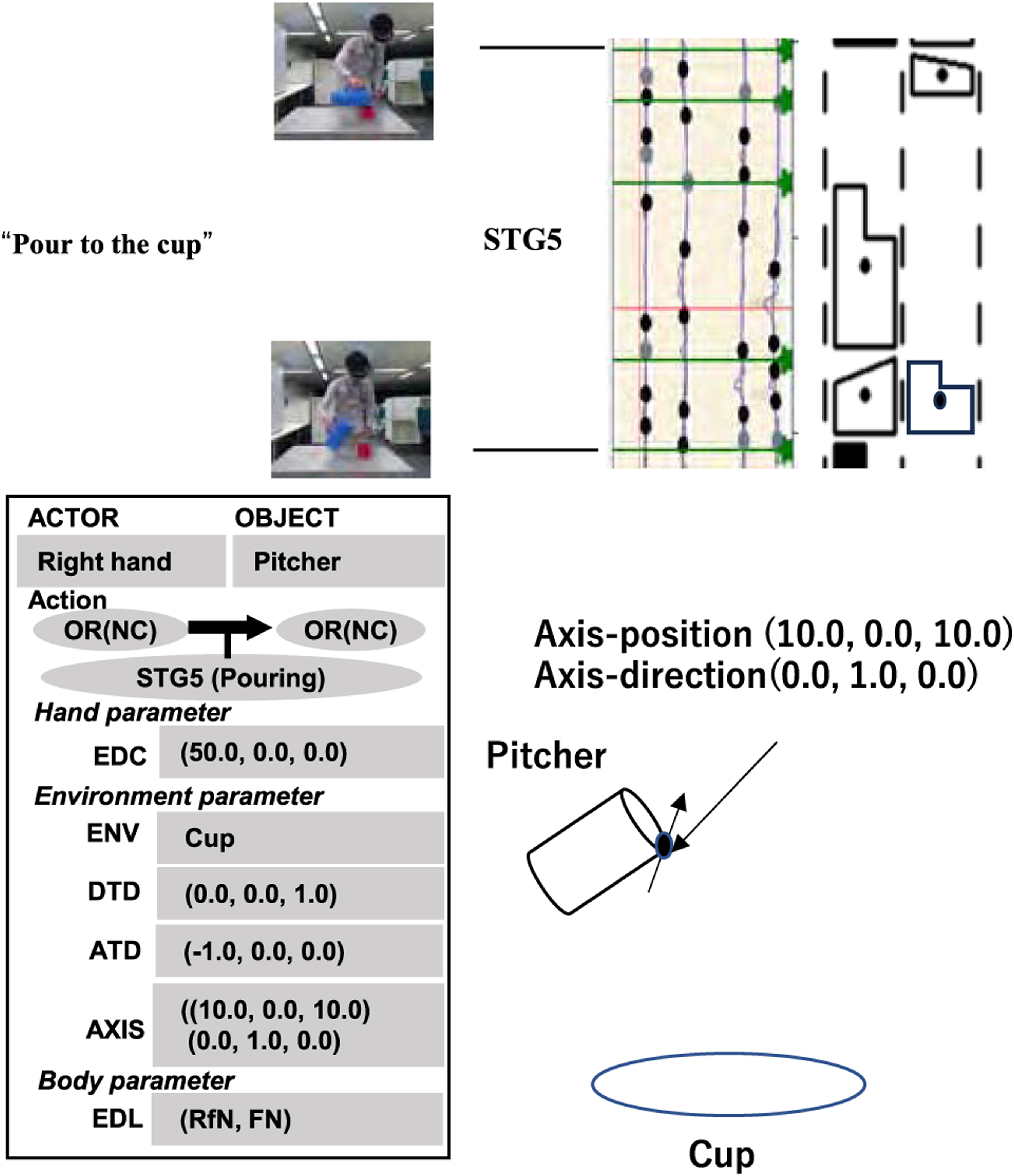
This task model performs a direct copy of the human actions. However, practically, it is necessary to modify the robot strategy by adjusting the flow rate and determining the appropriate amount of liquid quantity in the cup. Similar to the discussion of goal planning in the wiping demonstration, we will address this in future work.
8. Conclusion and discussions
This paper describes the utility of introducing semantic constraints in addition to physical constraints when training a robot assistant to perform household actions from observation. The main argument of this paper is that it is difficult, if not impossible, for a robot to understand the hidden intention behind human actions from observation alone, and the task model formalized in terms of physical and semantic constraints, followed by verbal recognition, can be used for task recognition to understand the essence of the actions. The task model is designed as a framework to augment the understanding of the visual demonstration and collect the semantic and physical parameters that play an important role to link the demonstration to the execution by the robot.
8.1. Discussion: Top-Down vs bottom-Up
Top-down LfO differs from bottom-up LfD in two ways. First, LfD focuses primarily on learning the optimal overall trajectory without explicit semantic understanding of each part of the trajectory to play in the robot action. This makes it difficult, if not impossible, to transfer the obtained results to different hardware and in novel situations. LfO, on the other hand, performs indirect learning by acquiring an intermediate form, a task model, that captures only the important parts of the trajectory and specifies the roles of these parts, such as the part of the trajectory immediately before the end of a grasping task as the approach direction or the part immediately after the beginning of a pick task as the detaching direction, and translates them into the motion of different robot hardware. Thus, LfO can perform tasks for different situations by simply replacing parts of the execution module. For example, the same learned task models have been applied to two different robots in Sasabuchi et al., 2020; Takamatsu et al., 2022.
Another major difference between LfO and LfD is that the entire LfO system is designed and benefits from the top-down knowledge. Specifically, in this paper, tasks were defined in terms of surface contact transitions derived by the Screw and Kuhn–Tucker theories. These contact transitions allow us to determine what parameters or which part of the demonstration, such as detach direction observed immediately after pick-up action in a pick-up task, should be obtained. The idea is that this knowledge can be used to determine design guidelines for the daemon functions to collect task-specific features. In other words, the FOA of a daemon function can be controlled using this knowledge (Wake et al., 2020b). Secondly, although this paper’s main focus is not on the execution system, knowledge about contact transitions can also be used effectively in designing robot skills, which are the execution routines of tasks corresponding to each task model. Most skills are trained using reinforcement learning, and knowing at which dimensions contact is preserved and at which dimensions transitions occur is effective in designing reward functions and termination conditions in reinforcement learning. To align with skill learning via reinforcement learning, visual feedback may be incorporated into the skills to improve robustness at run time, and the transition dimension allows to determine the optimal direction of sensing and optimal features to sense (Miura and Ikeuchi, 1998). In other words, one of the major advantages of LfO is that by embedding top-down knowledge into the observation and execution system, the robustness of the system can be dramatically improved.
8.2. Discussion: Observation error
Although this one-shot learning of LfO is convenient and robust with embedded top-down knowledge, the possibility of recognition errors still cannot be ruled out. Since the main topic of this paper was the introduction of semantic constraints, for the sake of simplicity, only one-time and unidirectional teaching from human to robot was explained. However, by making this teaching system interactive, the robot can ask the human to demonstrate or confirm recognition results for ambiguous points. For this purpose, a multimodal user interface was designed for the system to display intermediate recognition results to the user and to allow corrections to be made (Ikeuchi et al., 2023; Wake et al., 2022). Again, the process is simplified because only the main points are displayed and corrected by the task models given by the top-down knowledge.
This system used a method of describing a set of task groups surrounded by grasping and releasing in language. In general, how much to describe at a time is one of the research challenges. We also implemented a step-by-step method in which each task is described in language as the finest granularity (Wake et al., 2022). We compared this system with such a step-by-step system and concluded that this system is easier to use. Regarding the timing of giving verbal instructions, there are two options: explaining during the performance of the physical demonstration or before the performance. It is known that the double task of performing certain actions while speaking is a great burden, especially for the elderly, and for this reason, the method of speaking and then performing was chosen. It remains to be seen to what extent this is affected by age.
8.3. Discussion: Verbal input
In designing this system, we used a verbal description method for each action, which is explained by a single verb and a single task group. A future direction is to make it possible to explain a series of actions in a global description. In doing so, it is necessary to consider how many task groups should be included in a single sentence. To this end, we are conducting research to analyze cooking videos, define frequent groups of task groups called task cohesion, and pre-register these task cohesion using a UI (Yanaokura et al., 2022). In parallel with this, we have recently obtained preliminary but highly promising results on the possibility of decomposing common input sentences into task groups by providing appropriate prompts to ChatGPT. Here, we were able to generate a sequence of task models that could be performed by the robot by providing, as prompts, an environment description, a set of skills from the skill library, and the role of the ChatGPT (Wake et al., 2023). However, the skill parameters were obtained from the human demonstrations. In the future, we consider that a hybrid of this task cohesion pre-registration method and a ChatGPT generation method is promising direction.
In terms of matching between language and demonstration, the demonstrator intentionally pauses a little longer at critical breaks and postures to make it easier for LabanSuite to detect such breaks. The basic idea is that this system is designed to be a friendly teacher, rather than a general observation system that can handle adversarial situation. In other words, the demonstrator actively employs brief stops as a means of communication between the demonstrator and the system. In fact, this is a very common practice in the world of dance, especially in traditional Noh Japanese dance, where such a momentary pause is called “Tome,” to be used to impress the audience with a peculiar posture at that time. Probably, for similar reasons, Labanotation uses brief stops of some body parts as sample timings for Labanotation symbols. Applying LabanSuite to ordinary video may result in over-segmentation or under-segmentation in some cases. The use of DP has proven a promising way to remedy this issue (Yanaokura et al., 2022). Furthermore, since GPT-4 can handle images and videos as well as language, we believe that using the next generation of generative AI systems will be a very promising direction to solve the matching issue as well.
8.4. Discussion: Dual arm operations
In this paper, we consider only a one-armed robot with a task sequence that starts with grasping and ends with releasing. The movement of an arm, whether right or left, can be performed by describing it in the Actor slot of a task model. Two task sequences can be executed in parallel. However, in the case of a two-arm cooperation, we must consider the synchronization of two task sequences. For example, consider the verbal instruction of “Open the refrigerator with the right hand and take out a bottle with the left hand.” This instruction can be decomposed into two task sequences that begin with grasping and end with releasing: the right hand opens and closes the door, while the left hand picks up and places the bottle. The same argument applies to cases of handover tasks. However, the end time of the door-opening action must be the start time of the grasping task, and such a synchronization problem must be solved at the task recognition level. Solving this synchronization problem from the verbal instruction and/or task sequence analysis is very interesting, but should be left as future research.
Footnotes
Acknowledgments
The authors thank Prof. Etsuko Saito, Professor of Core Research Human Science Division of Ochanomizu University, and Prof. Midori Otake, Emeritus Professor of Tokyo Gakugei University, for helpful discussions on elderly supporting techniques. We appreciate their providing miso soap and beef stew making videos. In implementing the actual system, we received a lot of help from Riku Arakawa and Iori Yanokura of the University of Tokyo, Saki Yamamoto of Ochanomizu University and Atsushi Kanehira of Microsoft
Declaration of conflicting interests
The author(s) declared no potential conflicts of interest with respect to the research, authorship, and/or publication of this article.
Funding
The author(s) received no financial support for the research, authorship, and/or publication of this article.