
Abstract
Robots usually establish contacts at rigid surfaces with near-zero relative velocities. Otherwise, impact-induced energy propagates in the robot’s linkage and may cause irreversible damage to the hardware. Moreover, abrupt changes in task-space contact velocity and peak impact forces also result in abrupt changes in robot joint velocities and torques; which can compromise controllers’ stability, especially for those based on smooth models. In reality, several tasks would require establishing contact with moderately high velocity. We propose to enhance task-space multi-objective controllers formulated as a quadratic program to be resilient to frictional impacts in three dimensions. We devise new constraints and reformulate the usual ones to be robust to the abrupt joint state changes mentioned earlier. The impact event becomes a controlled process once the optimal control search space is aware of: (1) the hardware-affordable impact bounds and (2) analytically computed feasible set (polyhedra) that constrain post-impact critical states. Prior to and nearby the targeted contact spot, we assume, at each control cycle, that the impact will occur at the next iteration. This somewhat one-step preview makes our controller robust to impact time and location. To assess our approach, we experimented its resilience to moderate impacts with the Panda manipulator and achieved swift grabbing tasks with the HRP-4 humanoid robot.
1. Introduction
When (rigid) robots collide—intentionally or inadvertently—with a rigid surface with a fairly high relative speed, the induced forces are impulsive and the contact state is uncertain. The shock propagates through the robots’ linkages into the joints and can severely damage some parts of the hardware, for example, the harmonic gears, weak linkages, and/or torque sensors (if any).
A common remedy is to carefully plan contact transitions with near-to-zero relative speed. However, this strategy cannot achieve specific tasks such as walking or jumping humanoids, hammering, and swift grabbing. For such tasks, the following robotic issues shall be improved concurrently: (i) design impact-resilient hardware (this is not tackled in this paper); and (ii) devise robust control strategies that switch the robot equations of motions and subsequent controllers following a transition policy called reset maps. The switching often requires a precise impact model and knowledge of additional parameters that depend on the environment and the robot, for example, the impact localization on the robot (and on the environment surface), the contact normal, and the exact impact time. Acquiring these parameters in-situ, instantaneously, and reliably is not always possible in practice.
An impact event is instantaneous and too short for a robot to react effectively. The impact duration (i.e., time interval) depends on the particular contact properties and the robot controller. In our recent studies (Wang et al. 2022b), an impact lasted for about 20 ms. This is the reason why, any impact-friendly control strategy shall act a priori and a posteriori.
To tackle on-purpose impact tasks safely, we challenge the possibility of building on our existing task-space control framework 1 instead of devising an entirely new control scheme. There are many reasons for this choice: (i) the framework has been proven to be efficient in handling complex industrial scenarios (Kheddar et al. 2019; Chappellet et al., 2023) and multi-robot control (Bouyarmane et al. 2019); (ii) to our best knowledge, on-purpose impact objectives using the task-space quadratic-programing (QP) formalism was not explicitly addressed; (iii) there is a relatively large community using it beyond the authors’ circle. Our guiding quest is to try as much as possible to enhance task-space QP control formalisms to deal with impact without considerably changing its structure. In other words: can we envision handling impact tasks simply by adding or reformulating task objectives and constraints without introducing new decision variables? As we see later in this paper, the answer to this latter question is yes, to some extent.
Formulating hardware impact limits
2
as additional QP constraints is straightforward but insufficient. The main problem is dealing with unexpected state jumps that may damage the robot. Unexpected because, in practice, even if an impact is planned to occur, there will be uncertainties on both contact time and location. The feedback velocity and force jump compromise the constraints’ feasibility. Consequently, we reformulate the usual constraints to account for such discontinuities. Then the QP is impact-aware and robust to state jumps by modifying the search space according to a one-step-ahead prediction of nearby intended (i.e., expected) impacts. As a result, the controller updates the optimized—and hence feasible—impact velocity reference in every control cycle (Figure 1). If the impact happened, the robot would fulfill both the hardware resilience and task-dictated constraints bounds. The impact-aware QP regulates the contact velocity in a modified search space to ensure that the post-impact state jumps are hardware-affordable.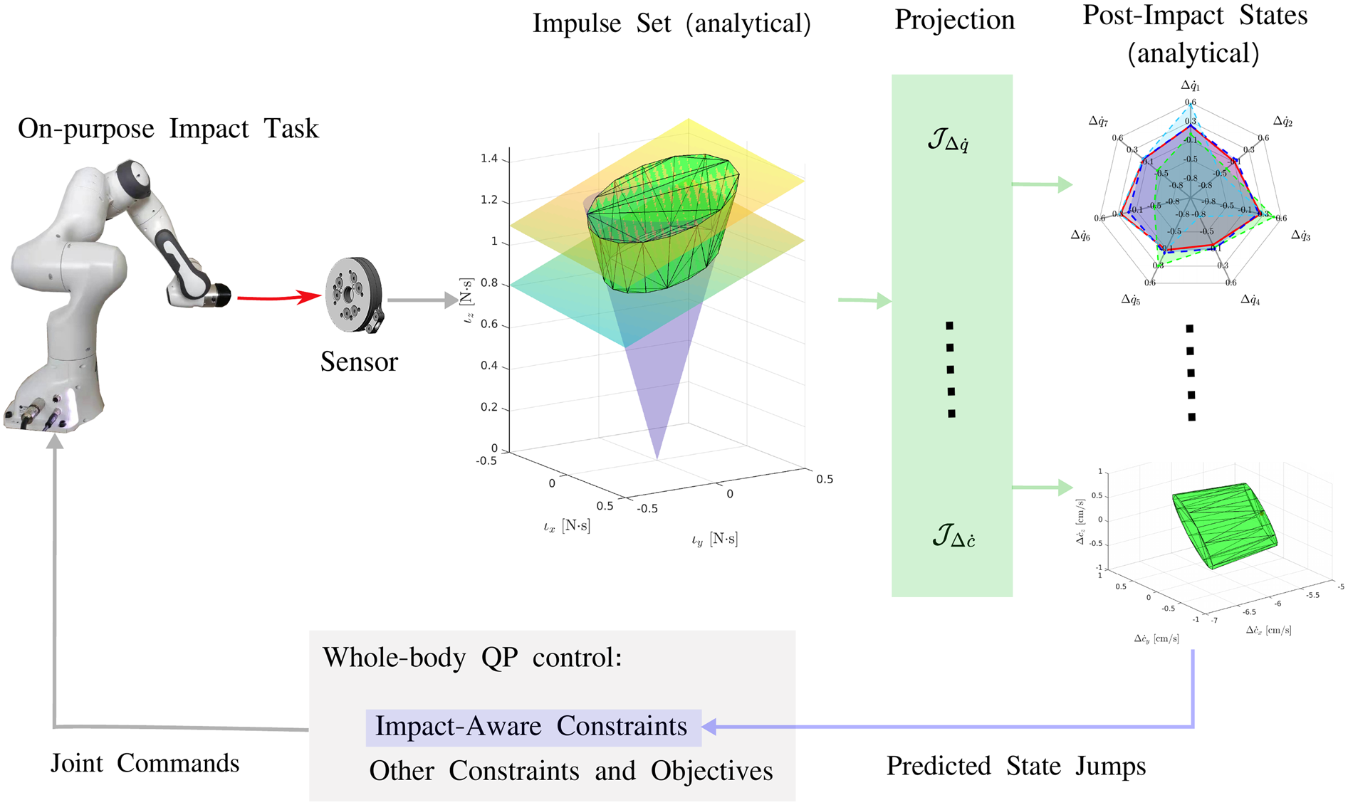
We summarize our main contributions as follows: C.1 bound the post-impact states (Sec. 4) with analytically constructed convex sets (half-space represented polyhedra), assuming the impact is frictional in three dimensions; C.2 bound a generic post-impact robot state with a closed-form impact-aware template constraint (Sec. 5.1); C.3 assess our impact-aware control design (Sec. 5.3) through experiments on the Panda manipulator and the humanoid robot HRP-4 (Sec. 6).
Our approach builds on top of our initial concept proposed in simulation for fixed-base robots in Wang and Kheddar (2019) and the preliminary extension to the floating-base robot in Wang et al. (2019). This work focuses primarily on task-space control, specifically addressing the incorporation of various sets of post-impact states. The modeling part of our controller relies on the assumptions and impact models derived from the extensive experimental studies in Wang et al. (2022a), (2022b); where we reported hundreds of impact experiments to benchmark different initial poses, impact joint configurations, and impact velocities for (kinematic-controlled) robots that are typically controlled in joint velocity (or position).
2. Related work
Second-order equations of motion, which are commonly used for robot control and planning, cannot effectively capture the impact dynamics. Thus, the robotics community has developed dedicated models to predict the impact-induced state jumps. These models are derived from non-smooth mechanics theory, see, for example, Stronge (2000). Sec. 2.1 summarizes the main models used in robotics starting from the seminal paper by Zheng and Hemami (1985) in the 1980s. Given the impact mechanics, Sec. 2.2 briefly reports on mitigating impacts by a few ideas in absorbing shock through hardware design and a large part of control strategies in various robotic impact tasks.
2.1. Impact modeling
Because robots are commonly made from structures and links that are rigid; and because of the real-time constraints in robot control and planning, impulsive motions are modeled based on rigid-body dynamics in contrast to the computationally demanding approaches such as stress wave or finite element deformation models applied by Pashah et al. (2008).
Recently, Wang et al. (2022a) found that for kinematic-controlled robots, it is more accurate to formulate the momentum-conservation equations in the task space and assume the robot to behave like a composite-rigid body during the impact event. Formulations relying on joint-space generalized momentum, for example, Zheng and Hemami (1985); Lankarani (2000); Khulief (2013), do not account for high-stiffness joints and apply for compliant robots, for example, pure-torque controlled robots or partially actuated pendulums.
In the impulse space, the momentum conservation defines the plane of compression, and Coulomb’s friction law defines the friction cone, see Stronge (2000); their intersection points conservatively bound all the candidate impulses of an impact.
When the impulse is two-dimensional, post-impact contact modes are limited (and numerable), i.e., bounce, sliding, reverse sliding, and sticking. Checking the intersection points against the candidate contact modes leads to an analytical impact model. The state-of-the-art impact mechanics (Jia et al. 2019; Lankarani 2000; Khulief 2013; Wang and Mason 1992) refer to this strategy as Routh’s graphical approach (Routh et al. 1955). When legged robots undergo multiple impacts, post-impact velocity and sliding direction are ambiguous (Remy, 2017). Halm and Posa (2019, 2021) recently extended Routh’s impact model for multiple planar impacts by reformulating it as differential inclusions. The novel formulation guarantees the solution’s existence. Casting the impact model as a linear complementarity problem, Halm and Posa (2021) developed a probabilistically complete algorithm for approximating the post-impact velocity set.
However, many tasks cannot escape from their full three-dimensional space dimension. Moving from 2D to 3D makes it impossible to determine the post-impact tangential velocity and impulse without numerical integrations, as observed by Stronge (2000) and Jia and Wang (2017).
We are interested in predicting the worst-case impulse to fulfill the hardware-affordable resilience bounds. In this paper, we analytically construct an impulse set in the three-dimensional space, whose interior covers all the candidate impulses that fulfill Coulumb’s friction cone and task-space momentum conservation. Optimization-based controllers and in particular task-space formulated as a QP, can integrate the half-space-represented impulse set as part of the constraints set to steer the robot to intended impact objectives by iterative control.
2.2. Handling impacts in robotics
Shock-absorbing mechanisms can contribute to increasing the robot's resilience to impact and ease the control aspects, for example, by providing more time for the controller to react to impacts. For example, Singh and Featherstone (2020) redesigned the quadruped leg’s mechanical structure to cancel the shock propagating to the floating base. Battaglia et al. (2009) devised a soft cover with thickness and material that depends on (i) the required maximum pre-impact velocity, and (ii) on sensing plus field-bus transmission latencies. Dehio et al. (2022) attached soft pads on end-effectors, this allows the implementation of an impact-aware preview controller for dual-arm fast grabbing of objects. Recently, this has been extended by Van Steen et al. (2023). In the bipedal walking domain, De Magistris et al. (2017); Pajon et al. (2017) mounted soft soles on humanoid feet for both leveraging impacts and casting terrains’ irregularities, which allowed walking on gravels. Since hardware is not the focus of this study, note that there is an active research perspective that we do not cover on hybrid hardware/control codesign to increase the robots’ resilience to impacts.
vThere are control strategies to avoid impacts. Pagilla and Yu (2001) modified the reference trajectories for zero reference velocity along the contact surface normal. The control design based on Zero-tilting Moment Point (ZMP) establishes contacts with near-zero velocity (e.g., Kajita et al. (2010)). Earlier, Grizzle et al. (2014) summarized that the impact-less reference trajectories are challenging to generate and inefficient to execute. Hypothetically, if we can leave aside the impact dynamics and assume that the associated state jumps remain hardware-affordable, Bombile and Billard (2022) proposed a sequence of time-invariant dynamical systems in a single control framework to continuously control the reach, grab, and toss motion; and even how to hit an object Khurana et al. (2021).
Impact plays a prominent role in robotic legged locomotion tasks, with the robot dynamics varying depending on the type and order of contact events. Complementarity problems uniformly represent a large range of (combinatorial) conditions that would require modeling using discontinuous functions, for example, Stewart (2000). Combining the robot equations of motion and the complementarity conditions, the complementarity dynamical system (CDS) summarized in Hurmuzlu et al. (2004) offer a general conceptual tool to describe a walking robot’s dynamics, see also Brogliato (2003). Posa et al. (2014) applied the complementarity Lagrangian models for trajectory optimization. However, as mentioned by Grizzle et al. (2014), effective control design for CDS was not established until at least 2014. Recently, novel control and planning methods have emerged for CDS control issues, such as avoiding explicit contact sequencing by contact-implicit trajectory optimization (Manchester et al. 2019).
To avoid discontinuous task-space tracking errors, Yang and Posa (2021) projected the tracking objectives to a subspace invariant to the impact event; see more recent results in Yang and Posa (2023). The impact-invariant subspace is a generalization of a preliminary observation by Gong and Grizzle (2020), that is, the angular momentum about the impact application point is invariant to the impacts.
Hu et al. (2007); Stanisic and Fernández (2012); Heck et al. (2016) model the dynamic contact transition with a mass-spring-damper approach. Yet, the continuity of the model cannot capture the non-smooth nature of impacts, thus failing to predict state jumps that could damage the hardware.
On the other hand, joint trajectory planners that are aware of the predicted state jumps can find the feasible impact motion. Konno et al. (2011) programmed the Fujitsu HOAP-2 humanoid robot to break wooden boards with a Karate chop. The impact motion consists of three-phase trajectories solved from nonlinear optimization. Konno et al. (2011) guaranteed standing stability by restricting the ZMP state jump. Rijnen et al. (2017) simulated an iCub robot impacting a wall employing two sets of pre-planned reference spreading trajectories (the first is pre-impact, the second is post-impact) generated from an off-line task-space QP controller. Another controller switched robustly from the pre-impact trajectory to the post-impact one upon impact detection. Recently, Van Steen et al. (2022) extended the reference spreading control to task-space trajectories. Konno et al. (2011); Rijnen et al. (2017); Shield et al. (2022); Van Steen et al. (2022) share the same impulse prediction following Zheng and Hemami (1985).
Off-line trajectory planning is computationally expensive and non-reactive. Tracking the trajectories through contact-rich dynamics raises additional issues, for example, impact timing, and invariant contact sequencing, see Johnson et al. (2016). Thus, the final state variation is discontinuous due to the perturbations. Pace and Burden (2017) summarized additional admissibility conditions that enforce continuous trajectory outcomes to be piecewise—differentiable with respect to the initial conditions. To prove the tracking error is infinitesimally contractive for mechanical systems, Burden et al. (2018) summarized conditions on the post-impact discretized system dynamics based on the stability index originally provided by Aizerman and Gantmacher (1958). However, Burden et al. (2018) have not yet validated the contraction conditions in real robot experiments.
Within the scope of this paper, we focus on fulfilling the hardware-affordable resilience bounds before and right after a single impact event rather than generating periodic impacts. Hence, control design tools aiming for cyclic behaviors, for example, Poincaré-map-dependent controllers (Grizzle et al. 2014) or reference spreading control (Rijnen et al. 2017), do not straightforwardly apply to our aim.
More than a decade ago, Zhang et al. (2004) and Abe et al. (2007) proposed task-space quadratic-programing (QP)-based controllers for redundant manipulators and computer graphics. Task-space QP formulations are implemented for controlling redundant robots in recent years (Wang et al. 2014; Righetti et al. 2013; Kuindersma et al. 2016; Liu et al. 2016; Bouyarmane and Kheddar 2018; Djeha et al. 2023). Like trajectory planners, the proposed impact-aware constraints embed the mapping between the impact-induced state jumps and the pre-impact contact velocities. The constraints modify the QP search space such that the optimized solution conforms to hardware limitations and post-impact feasibility, that is, forward invariance.
3. Impact-unaware quadratic program-control
In this section, we recall the task-space QP control formalism following Bouyarmane et al. (2019) and highlight impact-induced problems. Sec. 3.1 presents the equations of motion; Sec. 3.2 and 3.3 detail the impact-affected constraints for joint and centroidal spaces; and Sec. 3.4 summarizes the QP controller without impacts.
3.1. Equations of motion
Given n actuated joints, a robot has (n + 6) degrees of freedom (DOF); additional 6 DOF concern, if any, the floating-base configuration in SE(3). Assuming m1 sustained contacts, the equations of motion write

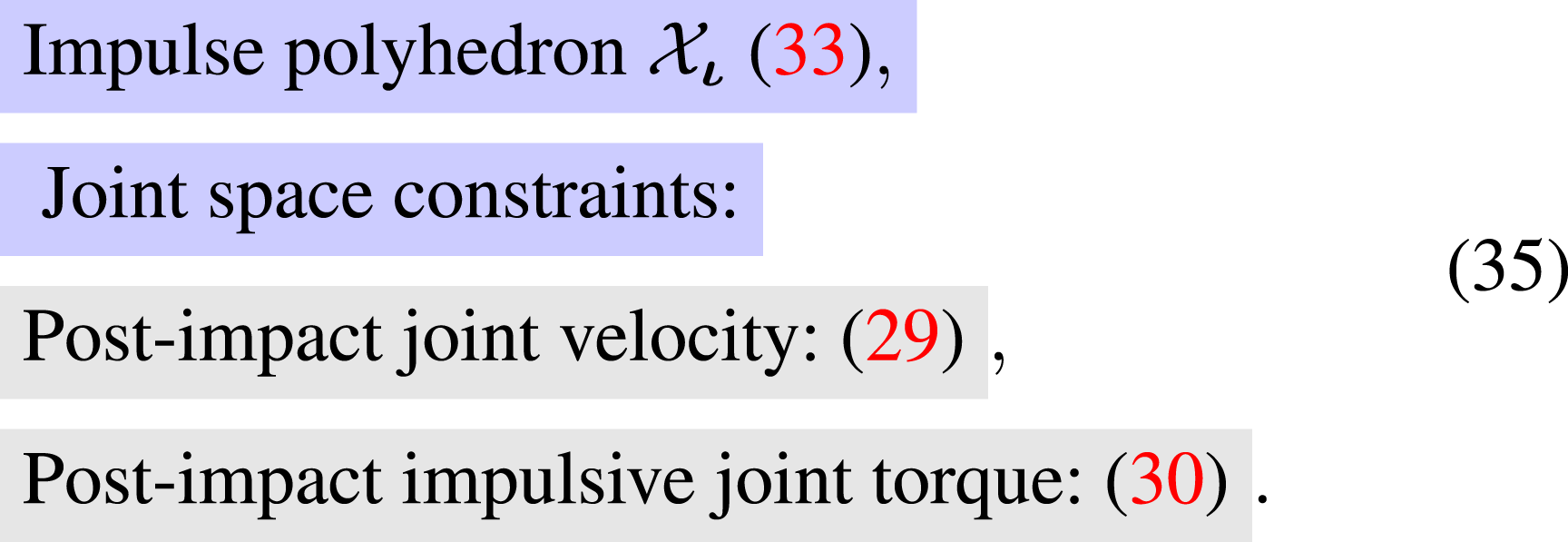
3.2. Joint-space constraints
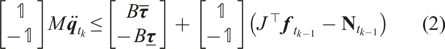
The equations of motion (1) fulfill the joint torque limits
Other constraints, such as collision avoidance, Cartesian space position constraints, actuated joint position, or velocity limits… do not express directly in the robot state acceleration. We can rewrite them as a function of the QP decision variable
3.3. Centroidal space constraints
In the humanoid case, Sugihara (2009) showed that the horizontal COM velocity

Due to the kinematic and actuation limits, the robot controller shall minimize its angular momentum

These equations, being specific to humanoids, are the basis of a dedicated work (submitted elsewhere) on multi-legged balancing under impacts.
3.4. Impact-unaware whole-body quadratic program controller
The optimization-based whole-body controller prioritizes multiple task objectives while imposing strict constraints
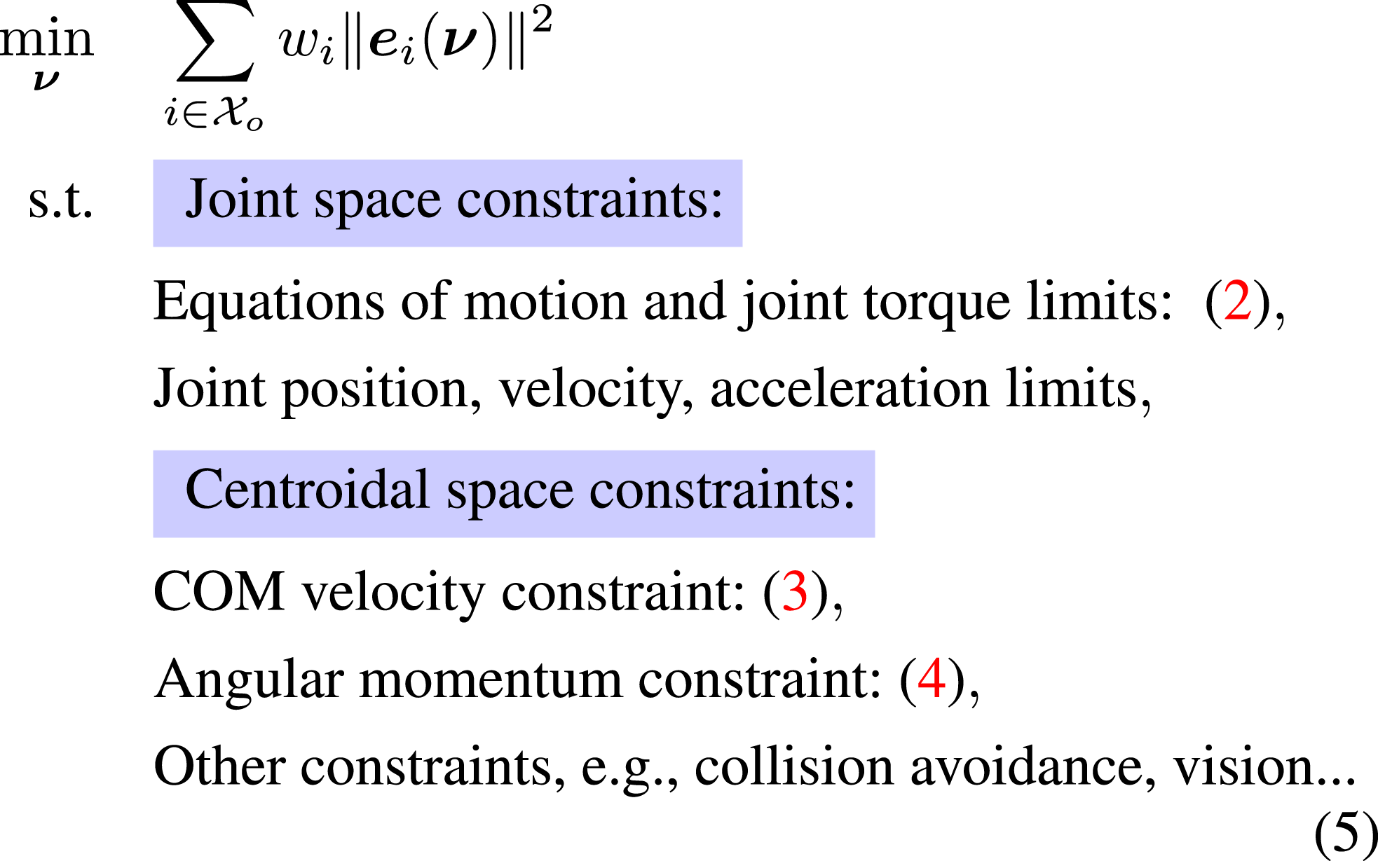
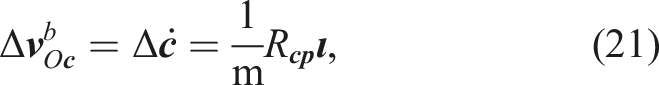
where
When it occurs, impact instantaneously changes the contact velocity. As a consequence, all the constraints that are expressed in terms of velocity, e.g., joint velocity bounds, angular momentum, and COM velocity… will have their value changed with a substantially high increment. As a result, the QP search space might shrink instantly to an empty set, rendering the QP infeasible for the subsequent control iteration.
Our main idea is to prepare such constraints to handle and be robust to such an abrupt change of the velocity values. If possible, without changing much the QP control formalism and framework. The controller will then have the dual objective to meet at best desired possible pre-impact speeds while keeping the QP controller feasible for the next iteration (i.e., forward invariant). That is to say, make the QP aware of the possible change in the tasks and constraints due to post-impact speed. We therefore explicitly need models that constrain the post-impact state with an analytically computed polyhedra in Sec. 4 and formulate impact-aware constraints in Sec. 5.
4. Modeling 3D frictional impact
Sec. 4.1 presents the impulse set that fulfills Coulomb’s friction cone and the task-space momentum conservation. The QP can integrate this set with an additional constraint. To numerically represent the impulse set, it’s common to discretize Coulomb’s friction cone as a polyhedron discretized-cone. Projecting the cone’s vertices onto different spaces, we constrain other quantities: (1) contact velocities in Sec. 4.2, (2) joint velocities in Sec. 4.4.1, and (3) COM velocities and angular momentum in Sec. 4.5. Utilizing heuristics, we also constrain the peak impulsive force in Sec. 4.3 and the joint torque jump in 4.4.2.
We use the coordinate frames illustrated in Figure 2 to define and exploit the impact model. Sec. 4.6 introduces the (1) impulse-to-velocity mapping in task space and (2) the transforms that can uniformly represent the velocities and impulses in the same frame. The red, green, and blue colors indicate the x, y, and z axis, respectively. The inertial frame 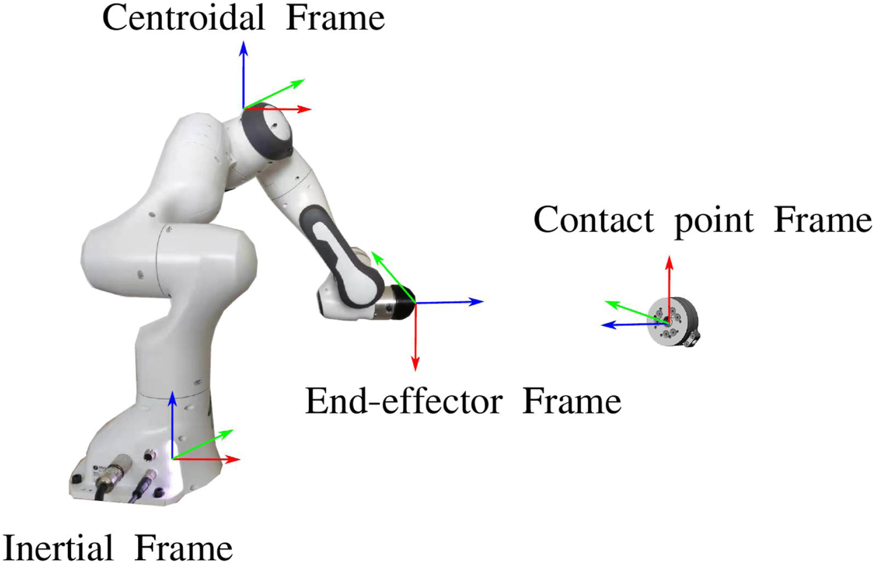
The whole-body QP can seamlessly integrate the polyhedra to enable impact-awareness since all the polyhedra are linear with respect to the pre-impact contact velocity and hence, to the QP optimization variables (joint accelerations).
4.1. Feasible impulse set
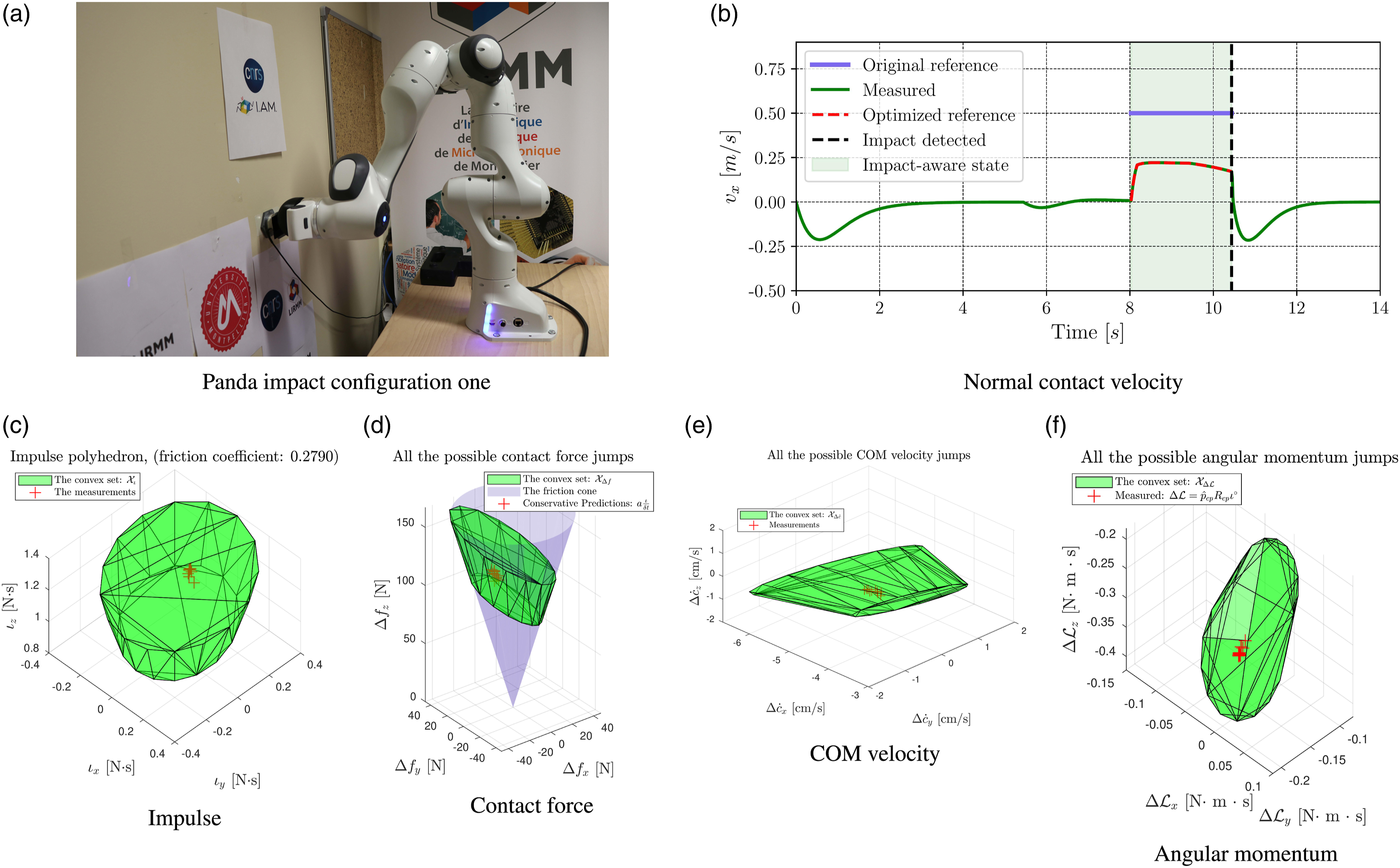
We assume the following statements are true during the impact event: A.1 The impact force is dominant compared to other forces. Consequently, generalized forces such as the centrifugal forces or motor command torques are negligible (Stronge 2000, Chapter 8.1.1). A.2 The impulse A.3 During the impact, the joint position changes are considered negligible according to Zheng and Hemami (1985); Grizzle et al. (2014); Siciliano and Khatib (2016); Konno et al. (2011). Yet, it is well-known that substantial changes are expected in the joint velocities; see recent experiments for kinematic-controlled robots in Wang et al. (2022b). A.4 The coefficient of restitution A.5 The contact area is tiny compared to the robot's dimension, hence, a 3D point-contact model is appropriate (Chatterjee and Ruina 1998). A.6 The impact induces significant impulsive forces and negligible moments (Stronge 2000; Chatterjee and Ruina 1998). A.7 The impacting limb has a minimum of three degrees of freedom. The joint configuration is not singular. For the Panda impact configuration in (a), the impact-aware QP solver adjusted the normal contact velocity, as depicted in (b). We visualize the polyhedra that constrain the impulse (12), the peak contact force (14), the COM velocity (17), and the angular momentum (18). All the measurements (red crosses) satisfy the corresponding polyhedron-represented sets.
■
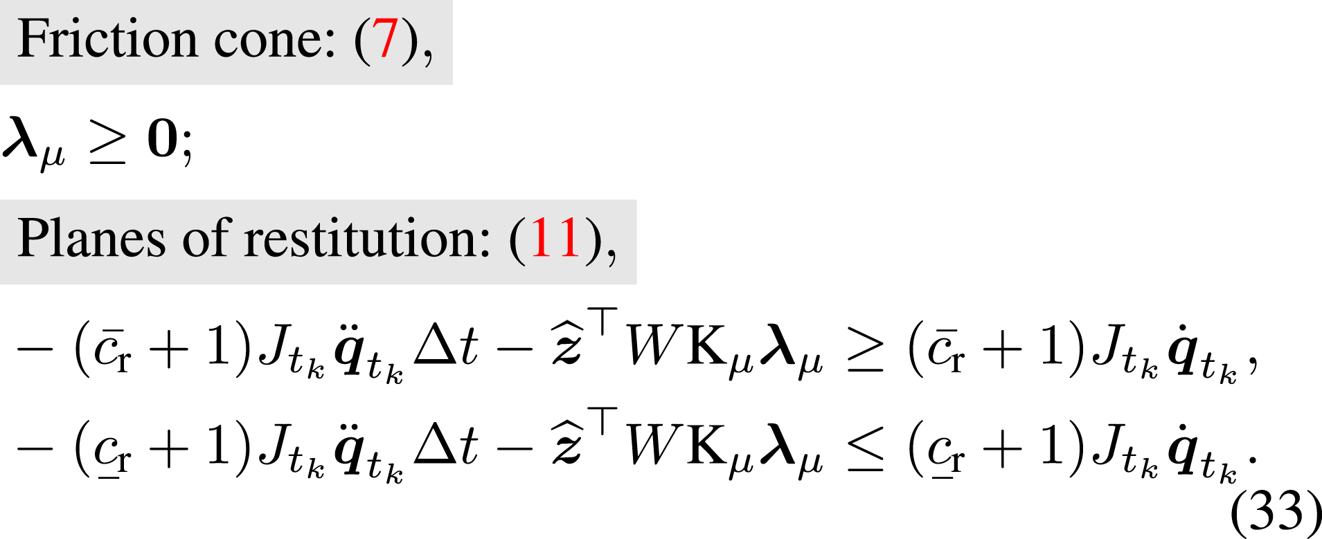
The feasible impulse set is the intersection of: (1) The discretized Coulomb’s friction cone, see Sec. 4.1.1; (2) The two planes of restitution given the coefficient of restitution
We analytically represent the impulse set as a polyhedron, whose interior points are candidate impulses fulfilling assumptions A.1–A.7.
4.1.1. Coulomb’s friction cone
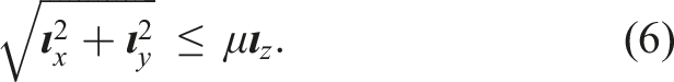
The impulse fulfills Coulomb’s law of friction (Jia et al. 2019; Stronge 2000). We discretize the friction cone (in A.2) with N
μ
vertices

4.1.2. Planes of restitution
During the impact event, the contact velocity

While Stronge (2000) and Jia and Wang (2017) discuss impacts between pairs of rigid bodies, they do not provide a specific definition for the inverse inertia matrix (W) in the context of articulated robots. To bridge this gap, we introduce the W in Sec. 4.6.2, based on assumption A.3.
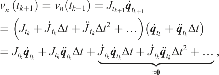
The impact event consists of the compression and restitution phases. The compression ends when the normal contact velocity is zero, that is,
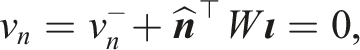


The negative sign arises because v
n
in the contact point frame

4.1.2. Impulse set
The intersection of the friction cone (7) and the two planes (10–11) defines the impulse polyhedron:

4.2. Contact velocity
Given the impulse set and the impulse-to-velocity mapping W, the contact velocity set is

4.3. Contact force
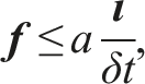
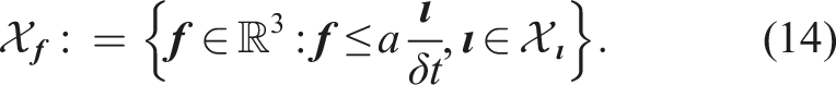
We suppose that the peak contact force is bounded by
4.4. Joint-space projections
4.4.1. Joint velocities
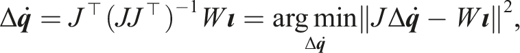
According to the recently proposed impulse-to-joint-velocity mapping by Wang et al. (2022b)

4.4.2. Impulsive joint torques
Given the peak contact force set (14) and the mapping J
⊤
Δ

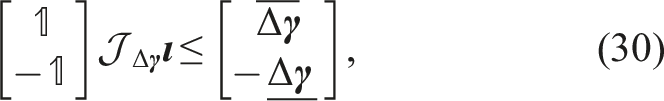
Impulses propagate through the mechanical linkages and have the potential to affect various components of the robot, including joint mechatronic implements such as gearboxes, torque sensors (if any), mechanical linkages, and covers. It is crucial to mitigate impacts to prevent damage to these components. The exact origin of the limitation is not of utmost importance, because, ultimately, a conservative approach is taken by considering the minimum or maximum allowable shock. The proposed QP controller embeds such constraints concurrently to address intentional impacts. Stall torque limits are established based on the robot’s equations of motion. These limits help ensure that a robot operates within safe operating conditions. The impact-aware constraint (30) imposes a distinct tolerance on the impulsive torque limits, allowing for control over the magnitude of the impact forces exerted on the robot. ■
4.5. Centroidal space projections
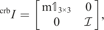
High-stiffness kinematics-controlled robots behave as a composite-rigid body during the impact event (Wang et al. 2022b). Thus, we have the COM velocity jumps
4.5.1. COM velocity
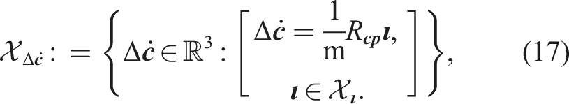
Given the impulse polyhedron (12) and the mapping (21), the COM velocity jump span the following set
4.5.2. Angular momentum
Similar to the derivation of (17), we have the set of angular momentum jumps given the mapping (22)

4.6. Implementation details
Sec. 4.6.1 summarizes the coordinate frame definitions, aligning with the notation used in impact mechanics (Stronge 2000; Jia and Wang 2017). Sec. 4.6.2 presents the equivalent inertial properties at the end-effector.
4.6.1. The coordinate frame specifications
We express the contact velocity and impulse in the contact point frame

In line with Murray et al. (1994), we represent a six-dimensional velocity as
The adjoint transformation, as described in Murray et al. (1994, equation. (2.57)), allows the mapping of a six-dimensional velocity or a wrench (or momentum, impulse) from one coordinate frame • velocity • wrench (or momentum, impulse)
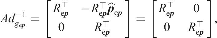
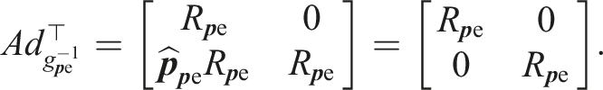
It is important to note that
4.6.2. The inverse inertia matrix
The inverse inertia matrix
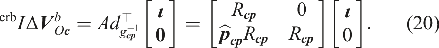
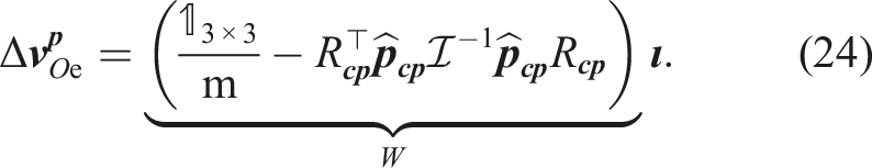
The adjoint map

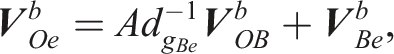
We compute the velocity jump
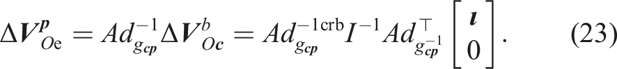
Thus, the inverse inertia matrix W is the 3 × 3 upper-left corner of
5. Impact-aware control design
In this section, Sec. 5.1 presents the impact-aware template for constraints; Sec. 5.2 substitutes the impulse polyhedra and robot states of interest into the template constraint.
Due to the modified search space, the impact-aware QP summarized in Sec. 5.3 is feasible (under our hypotheses and correct values of the bounds) if the impact occurs in the next control cycle, i.e., all the post-impact states fulfill hardware resilience bounds and the QP is robust to abrupt changes of the velocity.
5.1. Impact-aware constraints
We account for the post-impact state of constraints that are written in a generic quantity


We define a special Jacobian

The various special Jacobians are: • joint velocities • COM velocity • centroidal angular momentum

Thus, we reformulate (26) by substituting the impact-induced jump

5.2. Constraining the post-impact states
The template constraint (28) adapts to different quantities by choosing the corresponding half-planes D and the bounds
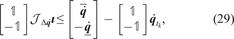
Joint velocity
Impulsive joint torque
Angular momentum

Horizontal COM velocity

5.3. Impact-aware whole-body quadratic program controller
To seamlessly integrate the impact-aware constraints (29–32) with respect to the impulse, we need to: (1) add the impulse generators (2) rewrite the pre-impact normal contact velocity
Assuming the impact occurs at the next control iteration, we approximate the pre-impact normal velocity as:
Substituting
Thus, we enhance the impact-unaware optimization-based controller (5) with the impulse polyhedron
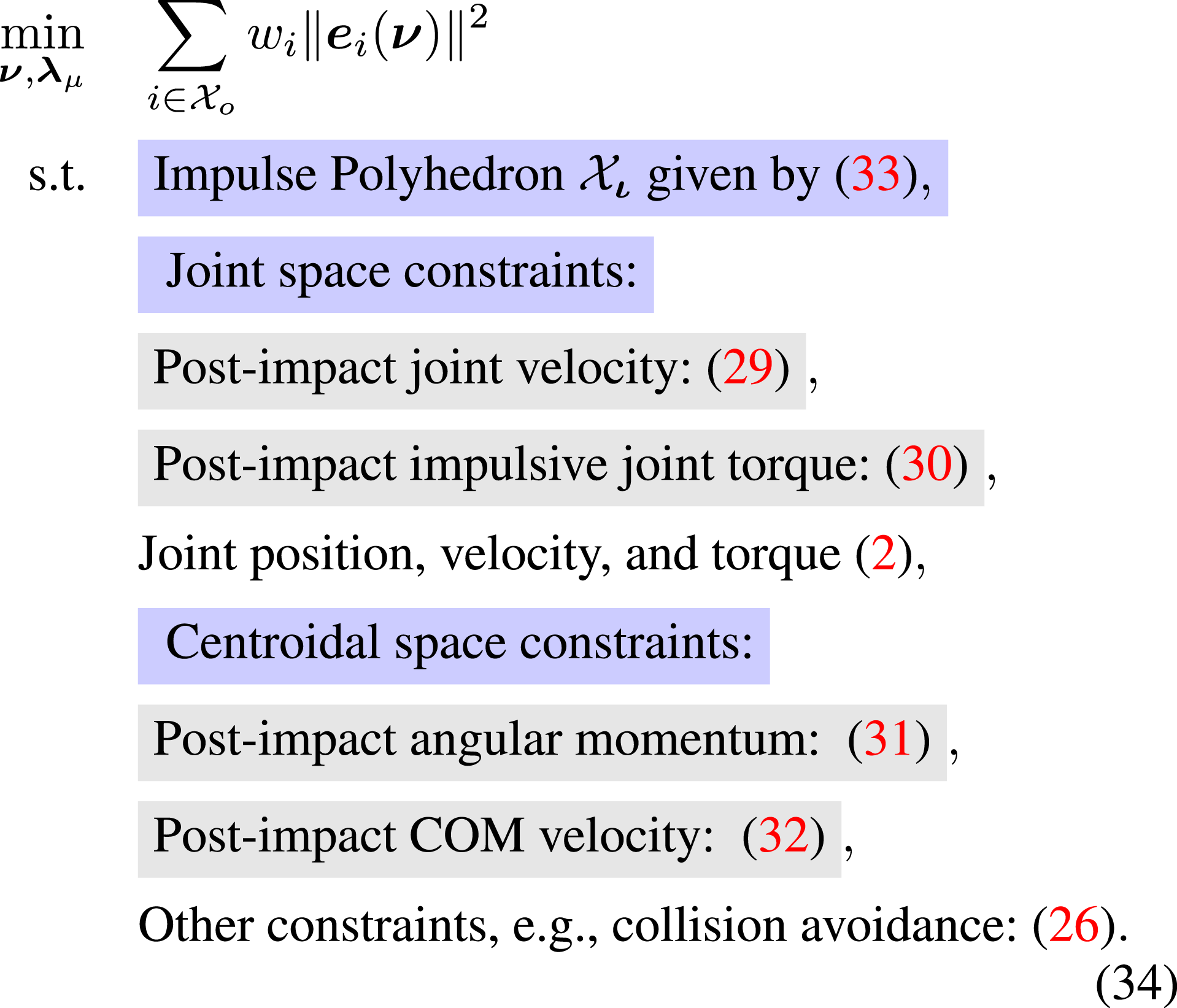
The improved formulation (34) shares the same objectives as the formulation (5) and modifies its search space such that all the post-impact states fulfill the corresponding bounds. Hence, (34) can decide on the highest feasible contact velocities if required.
We deactivate the impact-awareness upon impact detection by switching the QP controller from (34) to (5). Since the constraints associated with (34) are more conservative than (5), switching from (34) to (5) by full initialization does not lead to infeasible solutions.
Integrating (i.e., activating) impact-aware constraints by switching from (5) to (34) may lead to infeasible QP due to the actuation limits. Yet, this problem is common to any other usual inequality constraint, that is, triggered or inserted into the QP on the fly. Solutions exist for the case of one constraint, see, for example, Del Prete (2018); Djeha et al. (2020). Yet interaction among several constraints is still an open problem that we are currently investigating. ■
6. Experiments
We first assess our impact-aware control design with the Panda manipulator. All the manipulator’s post-impact states fulfilled the proposed impact model. The impact-aware QP (34) exploited the manipulator’s resilience bounds (the parameters are provided by our partner Franka Emika) to achieve the highest possible impact velocity; see the video. 3
The impact model is suitable for both the Panda and the humanoid robot HRP-4, since they are both stiff kinematic-controlled robots. Enforcing impact-aware constraints facilitated robot motions to become impact-friendly, thereby enabling the HRP-4 to grasp boxes with human-level swift motions. The detailed experiment description and the highlights are:
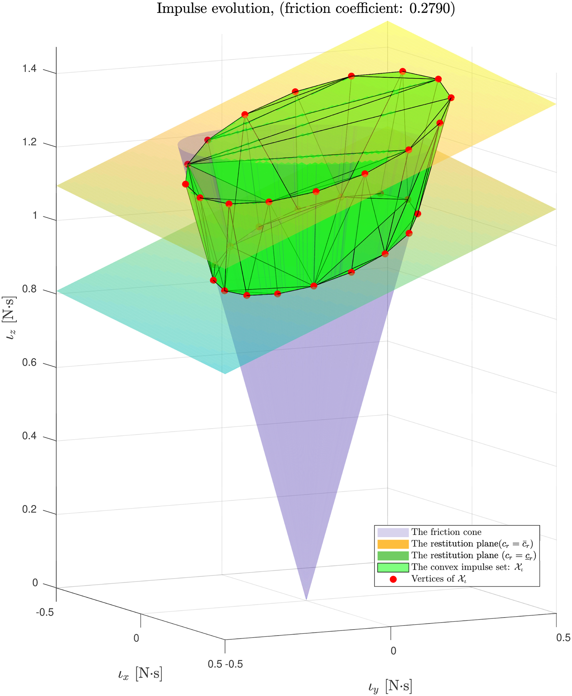
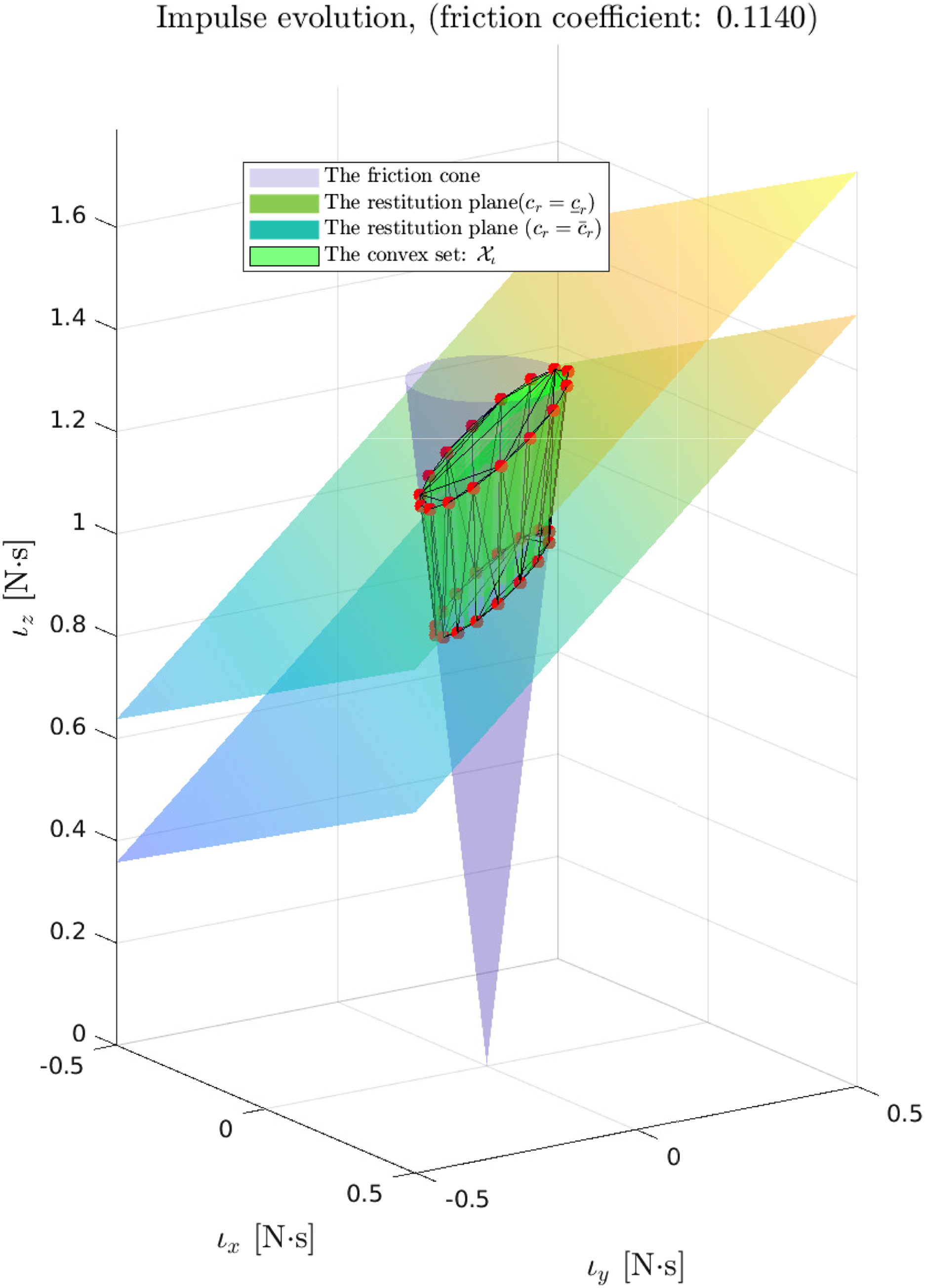
The Panda manipulator impacted an ATI sensor with two distinct configurations. In configuration one (refer to Figure 3(a)), the friction coefficient is 0.279, while in configuration two (refer to Figure 4(a)), the friction coefficient is lower with a value of 0.114 due to a different contact surface material. Comparing the impulse set of configuration one in Figure 5, the reduction in friction coefficient resulted in a narrower impulse set, as illustrated in Figure 6. In both cases, the robot promptly pulled back the end-effector upon impact detection. To mitigate random effects and ensure consistent observations, we conducted the experiment 10 times for each configuration. For the Panda impact configuration in (a), the impact-aware QP solver adjusted the normal contact velocity, as depicted in (b). We visualize the polyhedra that constrain the impulse (12), the peak contact force (14), the COM velocity (17), and the angular momentum (18). All the measurements (red crosses) satisfy the corresponding polyhedron-represented sets. We visualize the impulse set 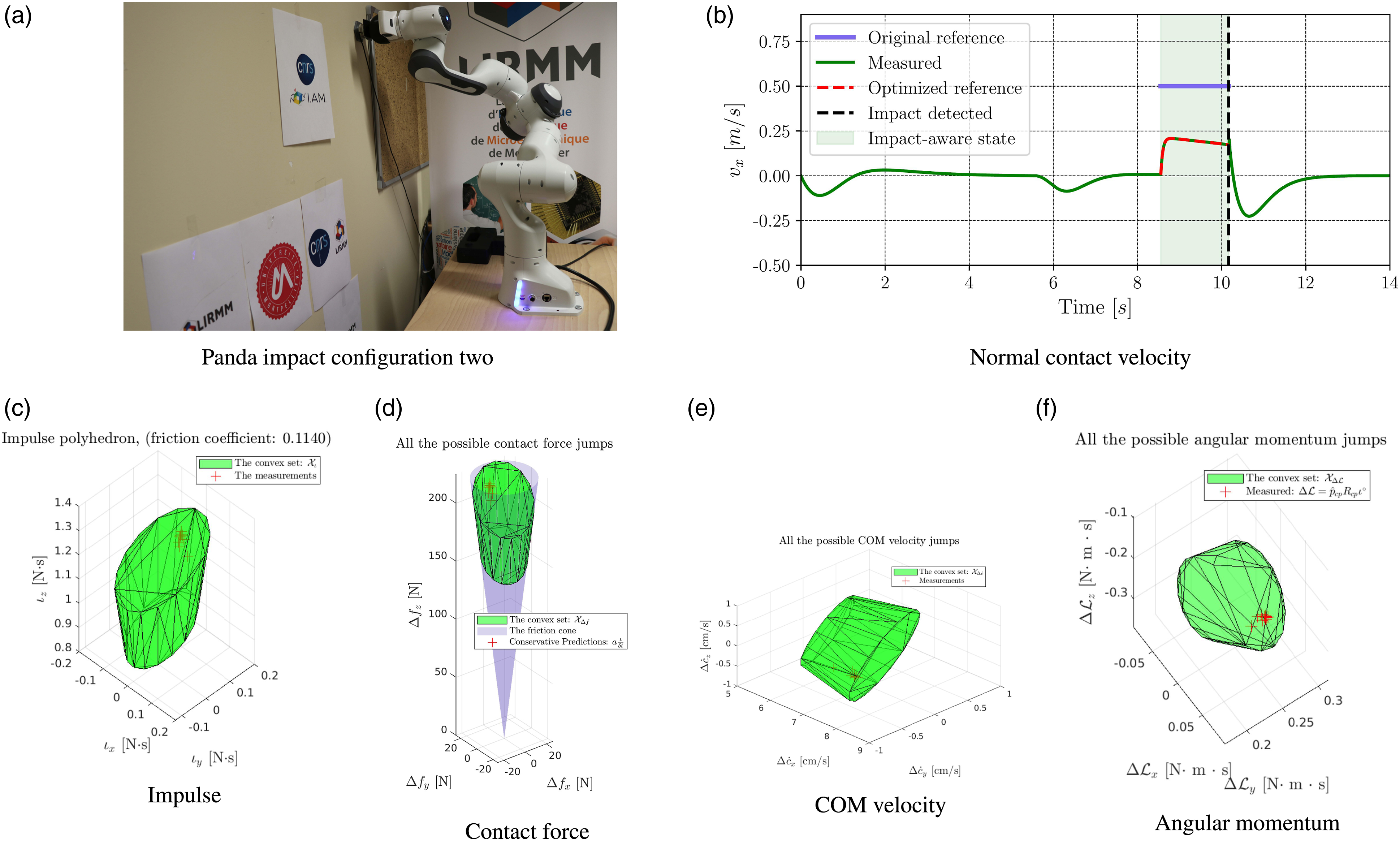
(H-1.1) All the impulses (measured by integrating the ATI force readings) fulfilled the impulse polyhedron proposed in Sec. 4.
(H-1.2) The impact-aware joint constraints are fulfilled.
(H-1.3) We empirically concluded that when the impulsive joint torque constraint (30) is active, the post-impact joint velocities are still away from the bounds.
(H-1.4) Given a high reference normal contact velocity, that is, 0.50 m/s, the QP autonomously steered the robot to the highest impact-aware feasible contact velocity in real-time.
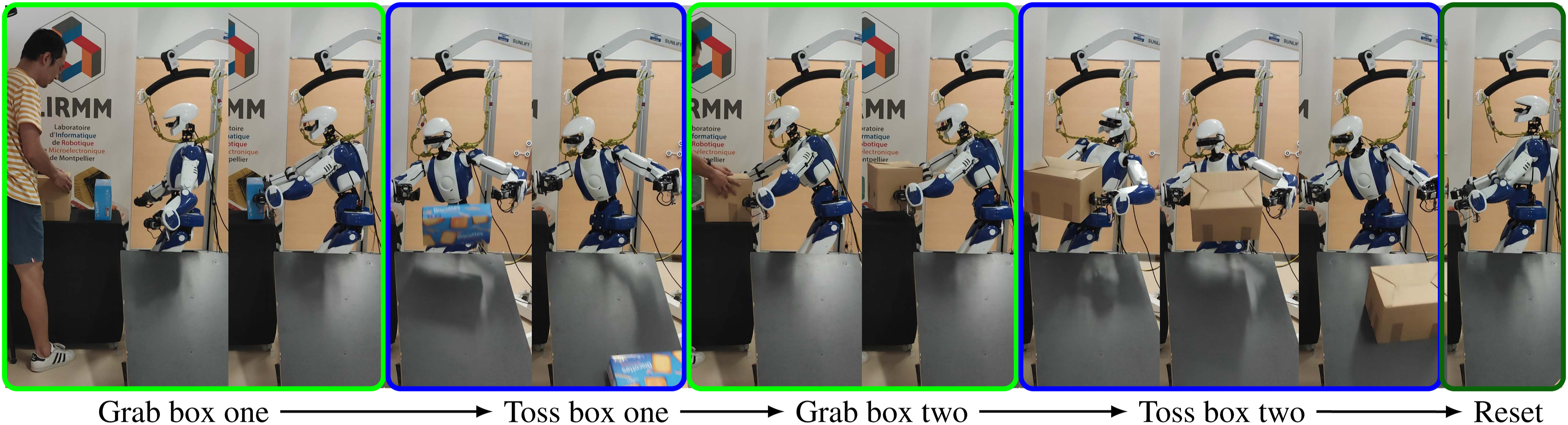
The HRP-4 robot swiftly grabbed two different boxes; see the snapshot in Figure 7. The two arm’s impacts are synchronized and symmetric. (H-2.1) Grabbing the box swiftly without marking any stop or slow at contacts. (H-2.2) The high contact velocities, that is, 0.25 m/s, were well-tracked. Snapshot of Experiment 2: the HRP-4 robot grabbed two boxes in a row with contact velocities of 0.25 m/s. The green-highlighted grab box states applied the impact-aware QP (34). During the blue-highlighted Toss box states, the robot grabbed the box with admittance control.
6.1. Panda manipulator experiments
Sec. 6.1.1 details the steps to measure the post-impact data; Sec. 6.1.2 customizes the impact-aware QP for the Panda manipulator; and Sec. 6.1.3 analyzes the results.
6.1.1. Data acquisition
We applied the open-source dynamics model 4 for the 7 DOF Panda manipulator from Franka Emika. It is worth mentioning that alternative models are also available. 5 , 6
We mounted a 3D-printed semi-spherical end-effector on the Panda robot to meet the point-contact assumption A.5, see Figure 2. The friction coefficient is μ = 0.279 for configuration one (Figure 3(a)) and μ = 0.114 for the second configuration (Figure 4(a)).
The impact event lasted for about 20 ms according to the recent experimental study we performed in Wang et al. (2022a). Subsequently, we measured the joint velocity changes in an interval (5 ms before and 15 ms after the impact) to be the joint velocity jumps
6.1.1.1. Coefficient of restitution
We construct the two planes of restitution (11) by choosing the upper and lower bound of the coefficient of restitution
According to the observations from hundreds of impact experiments (Wang et al. 2022a, Sec. VII.C), the kinematic-controlled robot impact is almost inelastic (the coefficient of restitution is close to zero cr ≤ 0.15) if the contact velocity is greater than 0.1 m/s. We choose the upper bound
6.1.1.2. Impact detection
The virtual force sensor of the Panda robot cannot capture the impact dynamics. Timely impact detection is essential for accurately observing the post-impact states. We achieved 3 − 6 ms detection time by thresholding the joint torque error
6.1.2 Controller formulation
A manipulator requires the following set of impact-aware constraints
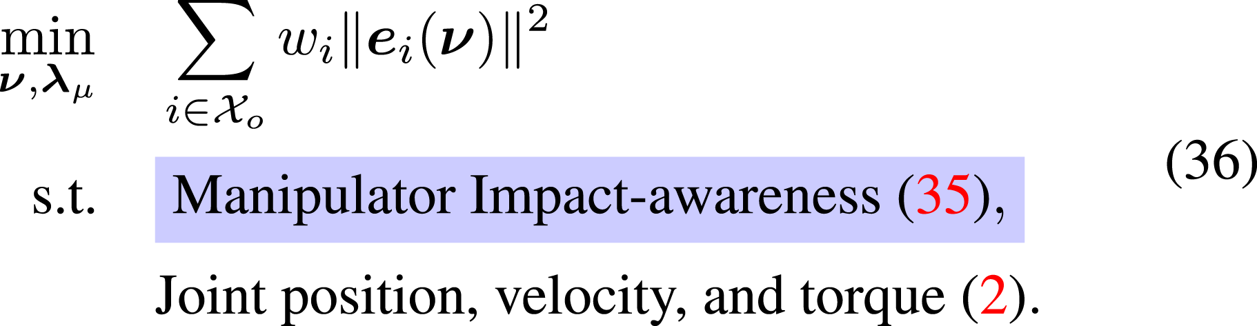
Thus, we customized the impact-aware controller (34) for the Panda manipulator as
The impulsive joint torque constraint (30) depends on the peak contact force. According to the contact force profiles (Wang et al. 2022a, Figure 4), we conservatively choose the impact duration δt = 18 ms and the positive scalar a = 3 to construct the peak contact force set
We assigned an unrealistically high reference contact velocity, that is,
6.1.3. Result analysis
6.1.3.1. The contact velocities
The impact-aware QP (36) solves the desired joint commands at each control iteration. Since the reference is too high to be precisely tracked, (36) modified the maximum feasible contact velocity as shown in Figure 3(b) and Figure 4(b) for the two configurations (H-1.4).
The light area in Figure 3(b) and Figure 4(b) (H-1.4) highlights the period during which the impact-aware constraints (35) modify the optimizer’s search space. The active constraint is the impulsive joint torque constraint (30), i.e., the QP solution in Figure 8 is close to the upper bound of 12 N·m. Due to the conservative choice of parameters, the measured impulsive joint torque Δ The measured and predicted impulsive joint torque jumps Δ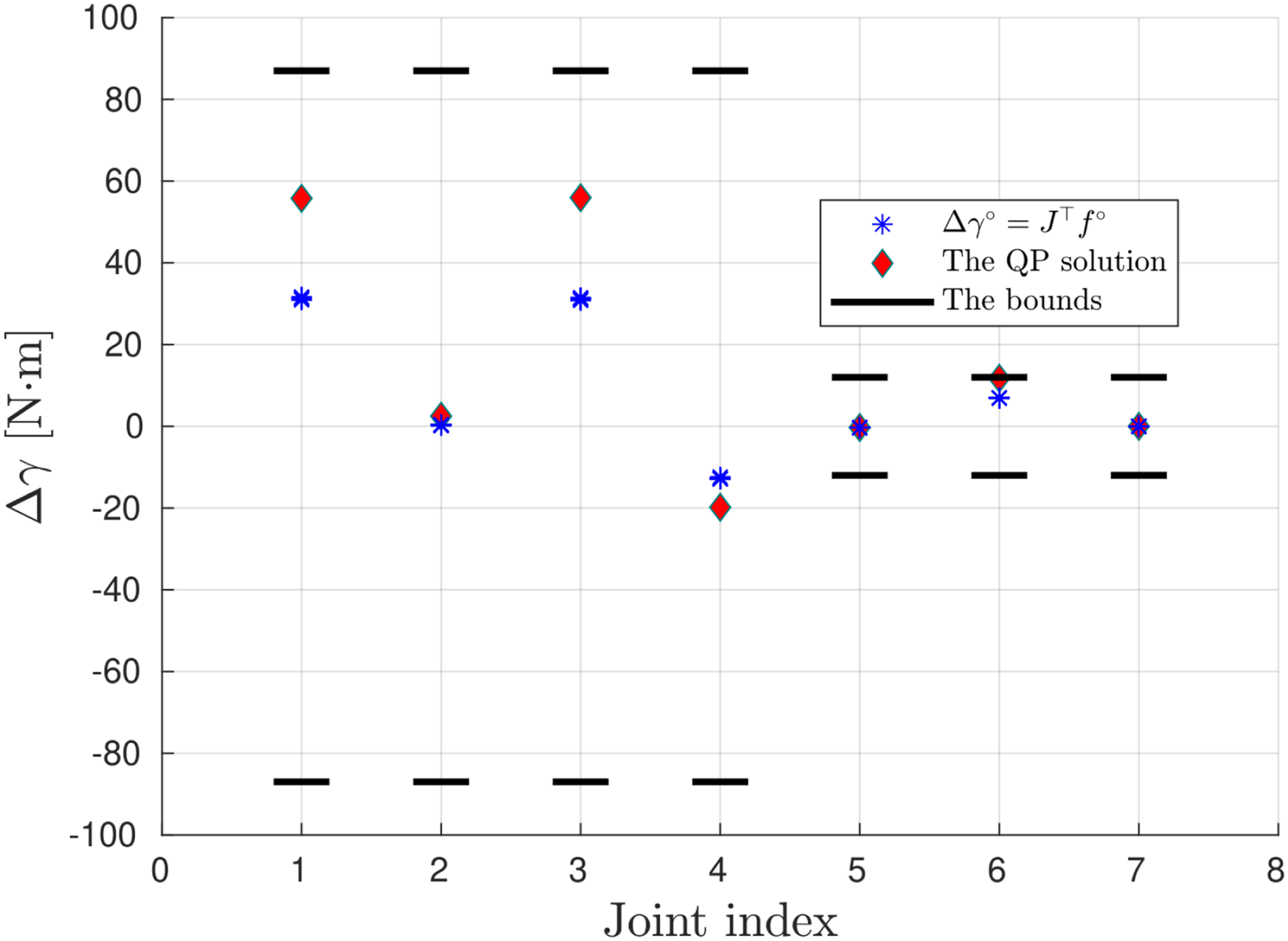
6.1.3.2. Fulfilling the impulse polyhedra
Figure 3(c) and Figure 4(c) illustrate that all measured impulses (from 2 × 10 experiments marked by red crosses)
Substituting
6.1.3.3. Fulfilling the impact-aware constraints
We focus on the first configuration, see Figure 3(a), as similar results are obtained for the second. According to the Panda robot descriptions, the joint velocity bounds are
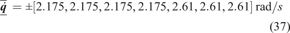
Figure 9 plots the measured joint velocity jumps 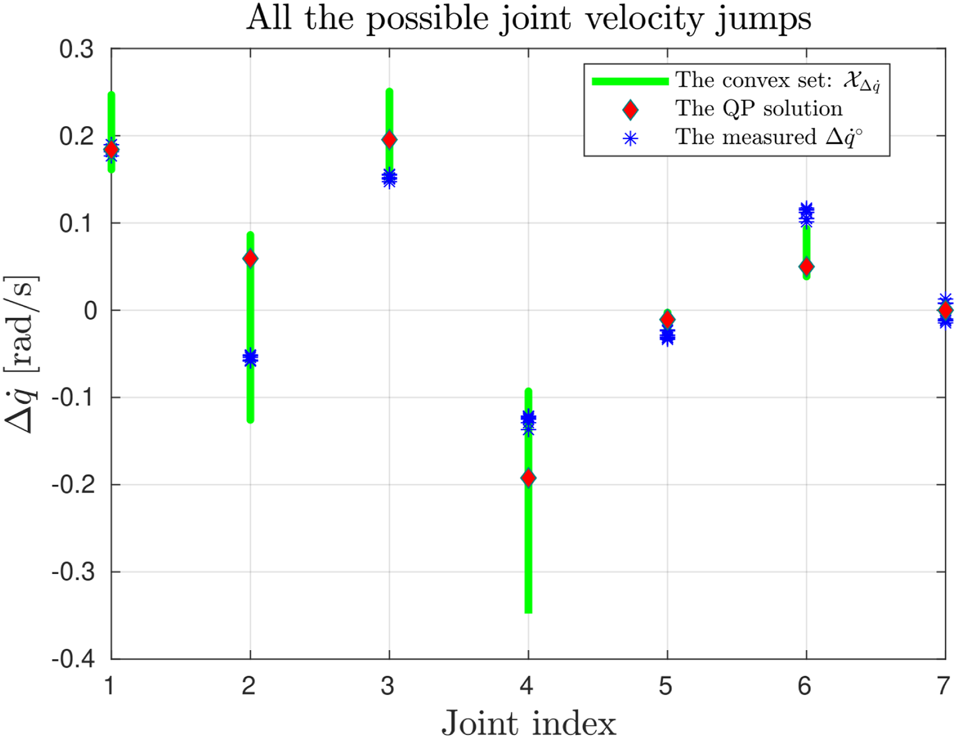
We define the impulsive joint torque bounds as

Substituting the measured impulse
6.2. Swift box-grabbing with the HRP-4 Robot
The HRP-4 robot swiftly grabbed a 1.08 kg box and another 0.38 kg box. The target contact velocity is 0.25 m/s. The robot did not reduce speeds for establishing contacts in both cases. The impacts are synchronized for the two hands, and the contact locations are symmetric.
6.2.1. Data acquisition
The HRP-4 is also high-stiffness kinematic-controlled (assumption A.3). The HRP-4’s geometric size is significantly higher than the contact area (assumption A.5). Thus, we adopt the same impact model used in Experiment 1. We bounded the coefficient of restitution by
The HRP-4 has two ATI sensors attached to the wrists. We can timely and reliably detect the collisions by thresholding the force measurement at 20 N.
We measured the impulses in Figure 3(c) and Figure 4(c) by sampling the force-torque sensors at 25,000 Hz. On the other hand, the HRP-4’s control system runs at 200 Hz. To study the effects of the low sampling rate on the impulse calculation, we compared the same impact experiments against different sampling rates; Figure 10 collects four sets of contact force profiles corresponding to 25,000 Hz, 1000 Hz, 500 Hz, and 200 Hz. As the mean impulses are similar, we concluded that it is acceptable to integrate force measurement sampled at 200 Hz to compute the impulses. The measured force curves in (a)–(d) were collected by repeating the same experiment: impacting the ATI force-torque sensor at 0.15 m/s by the Panda robot with the joint configuration shown in Figure 2. Despite the variations in sampling frequencies, the mean impulses 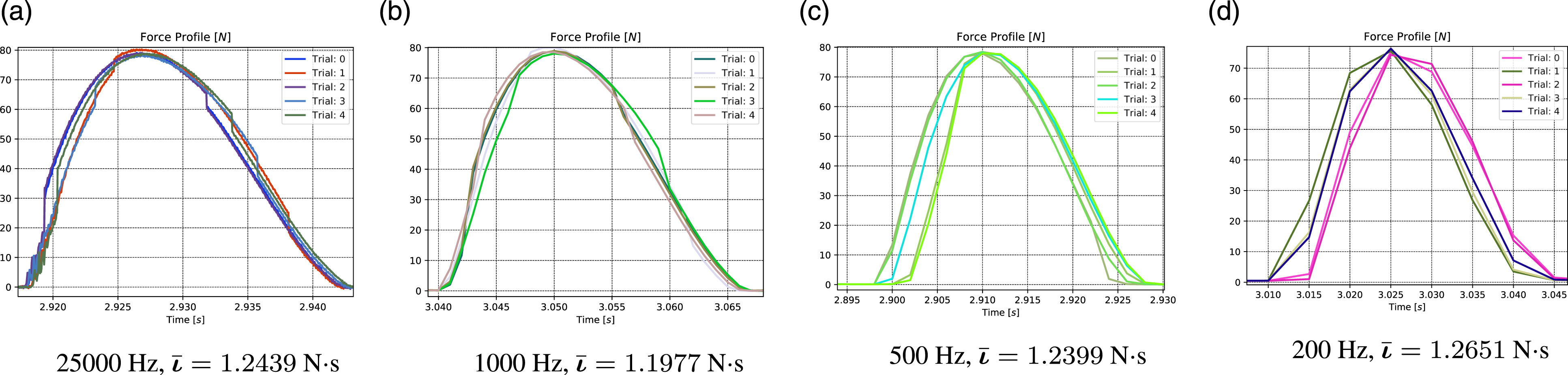
We placed two contact point frames at the two sides of the boxes. The frame axes are defined following a similar configuration as shown in Figure 2, in alignment with the impact mechanics definitions (Stronge 2000). We visualize their orientations in Figure 11. At the moment of impact, the origin of the two contact point frames shared the same translation with the corresponding end-effector. We color x, y and z axes with red, green, and blue, respectively. The two green polyhedra align with the two contact frames, representing the impulse sets 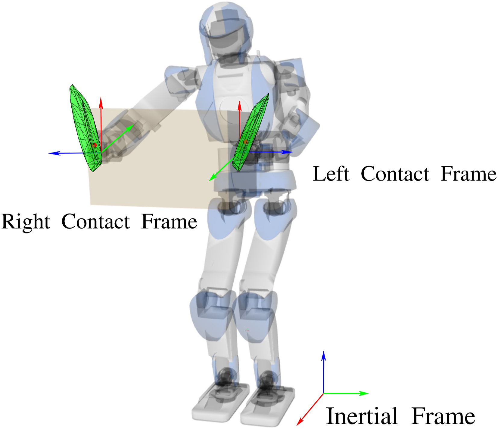
6.2.2. Controller formulation
We formulated the impact-aware constraints (36) for the two arms independently. The impact prediction employed the centroidal momentum matrix considering the kinematic chain from the floating-base link to the end-effector. The chain 7 weighs 11.63 kg.
Given the inertial frame
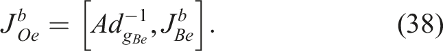
We align
Reactively optimizing the following QP generates the impact-aware whole-body motion (prior to impact)
where the impact-aware constraints (35) do not restrict the floating-base joint velocity or torque.
The QP (39) synchronized the two impacts to grab the box without exerting unnecessary rotating moments. The two arms followed pre-defined (off-line planned) trajectories considering the approximate location of the box. Upon impact detection, the QP activates the admittance task for the robot to firmly grab the box and then toss it to the ramp located on its left side. Following another pre-defined trajectory, the HRP-4 robot repeated the grabbing and tossing motion for the second box before resuming the initial configuration. The impact-aware constraints were fulfilled for the impacts.
6.2.3. Result analysis
The HRP-4 robot established the two contacts at 0.25 m/s, without slowing down or following pre-defined deceleration trajectories (H-2.1). We synchronized the two impacts (H-2.2) to grab the boxes.
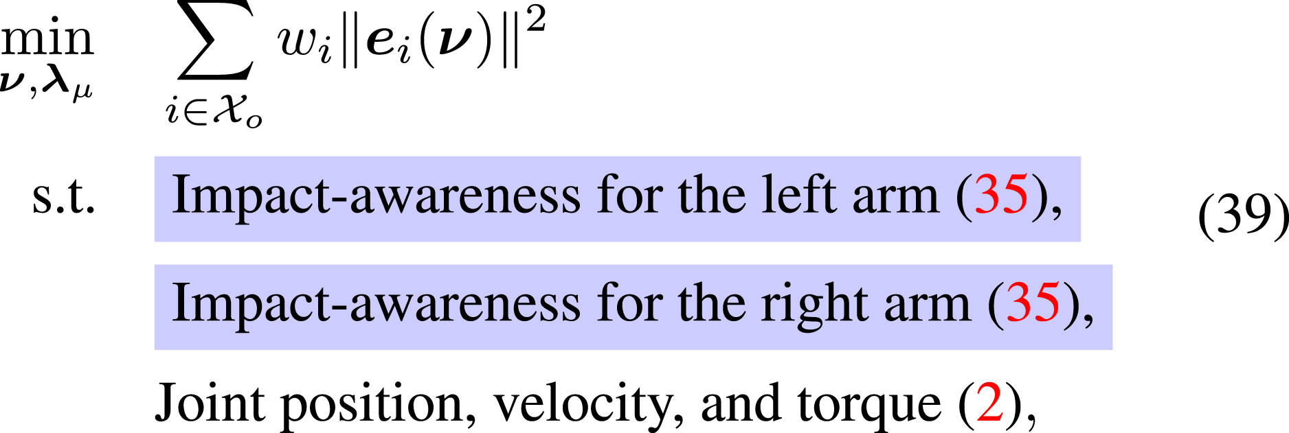
We independently model the two synchronized impacts on the two palms, see Figure 11. Given the ATI force sensor data, Figure 12 shows that the measured impulses are within the predicted impulse sets regardless of different situations. The HRP-4’s Experiment 2 includes four impacts (two arms with two grabbings each). The measured impulses in all situations are constrained within the impulse set 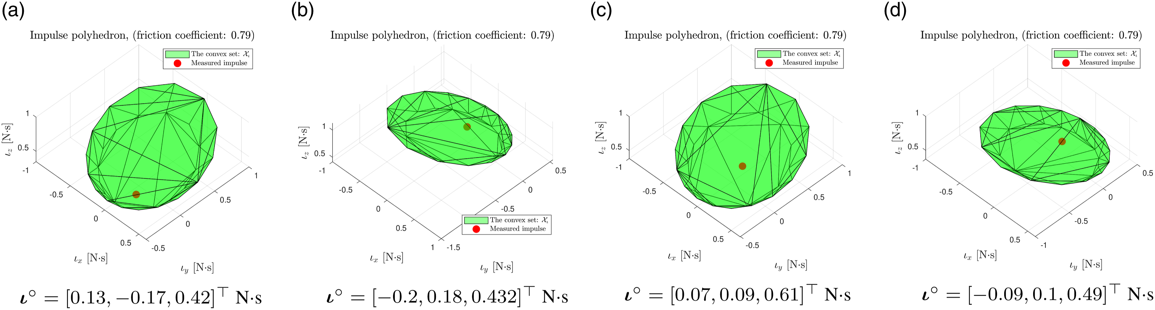
Figure 13(a), (b) plot the inertial frame end-effector velocities for the first and second grabbing. Contrary to Experiment 1, in both grabbing cases, the robot precisely tracked the reference contact velocities (as they are feasible w.r.t the embedded other constraints). The robot accurately tracked the reference contact velocities in Experiment 2. The light-blue areas in (a) and (b) indicate the period during which the controller activated the impact-aware constraints (35).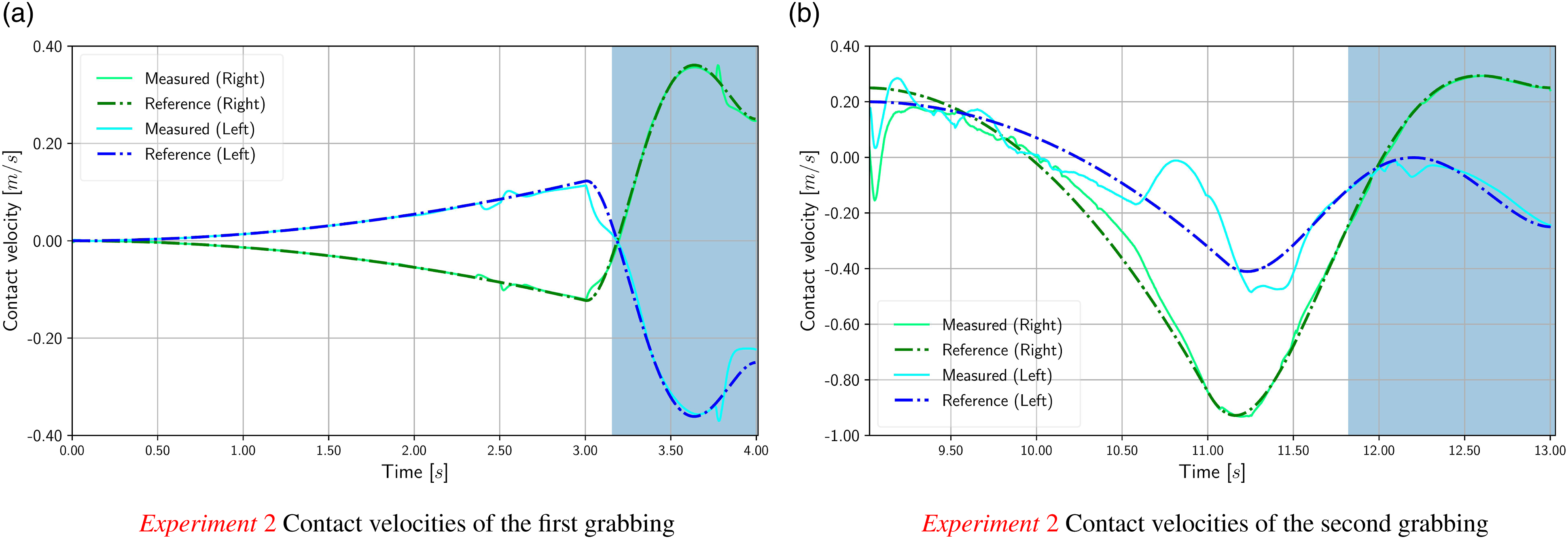
7. Conclusion and future work
We aim to enhance the task-space QP controller to deal with intended impact tasks. To the author’s best knowledge, our paper is the first to integrate frictional impacts in three dimensions into such optimization-based controllers.
We construct the impulse polyhedron to cover all the candidate solutions that fulfill Coulomb’s friction law and task-space momentum conservation. By projecting the polyhedra (half-space representation) into joint or task space, the controller gains awareness of post-impact states. As we are interested in a conservative solution, the polyhedra can accommodate model uncertainties by decreasing the angle of the friction cone or the restitution coefficients’ bounds.
The impact-aware constraints, represented as convex polyhedra, modify the whole-body QP’s search space according to the impact model and hardware-affordable resilience bounds. We assessed our approach with two robots: the HRP-4 humanoid and the Panda manipulator, both of which achieved high contact velocities without exceeding the hardware's resilience limits.
In future work, we plan to address certain aspects from a broader task-space QP control perspective, including robustness to handling interacting, potentially conflicting tasks, and the robust activation of constraints on the fly, regardless of their nature. We are currently obtaining promising results by formulating the QP as an MPC governor.
For aspects dealing more with impacts, we still have no solution if the critical bounds are not the correct ones (except being restrictive or conservative). Additionally, there is a need to devise a good shock propagation model for both fixed and floating-based robots. Our observations have also highlighted the necessity to reevaluate the standard dynamic balance criteria for humanoid robots under external impacts. We are currently preparing a separate paper dedicated to this topic. The humanoid experiments also revealed that handling multiple non-synchronous impacts on a moving object (floating box) is another shortcoming. This problem can be easily understood from a simple 2D toy example: rapidly grasping a 2D floating box (i.e., a box that can move under external forces) with two points robots controlled under task-space QP. In such cases, where the robots do not impact the object simultaneously, the object's mobility on the side opposite to the first impact can generate a higher relative velocity than expected. Although, by the time we wrote the paper, an interesting result was disclosed by Aydinoglu et al. (2022), it is important to note that their work did not integrate resilience constraints. We will thoroughly examine the scenario of multiple impacts on moving objects.
Footnotes
Acknowledgments
We thank Pierre Gergondet for his continuous support in setting up the mc_rtc controller.
Declaration of conflicting interests
The author(s) declared no potential conflicts of interest with respect to the research, authorship, and/or publication of this article.
Funding
The author(s) disclosed receipt of the following financial support for the research, authorship, and/or publication of this article: This work is supported by the EU H2020 research grant GA 871899, I.AM. project.