
Abstract
The Boreas dataset was collected by driving a repeated route over the course of 1 year, resulting in stark seasonal variations and adverse weather conditions such as rain and falling snow. In total, the Boreas dataset includes over 350 km of driving data featuring a 128-channel Velodyne Alpha-Prime lidar, a 360° Navtech CIR304-H scanning radar, a 5MP FLIR Blackfly S camera, and centimetre-accurate post-processed ground truth poses. Our dataset will support live leaderboards for odometry, metric localization, and 3D object detection. The dataset and development kit are available at boreas.utias.utoronto.ca.
1. Introduction
To date, autonomous vehicle research and development has focused on achieving sufficient reliability in ideal conditions such as the sunny climates observed in San Francisco, California, or Phoenix, Arizona. Adverse weather conditions such as rain and snow remain outside the operational envelope for many of these systems. Additionally, a majority of self-driving vehicles are currently reliant on highly accurate maps for both localization and perception. These maps are costly to maintain and may degrade as a result of seasonal changes. In order for self-driving vehicles to be deployed safely, these shortcomings must be addressed.
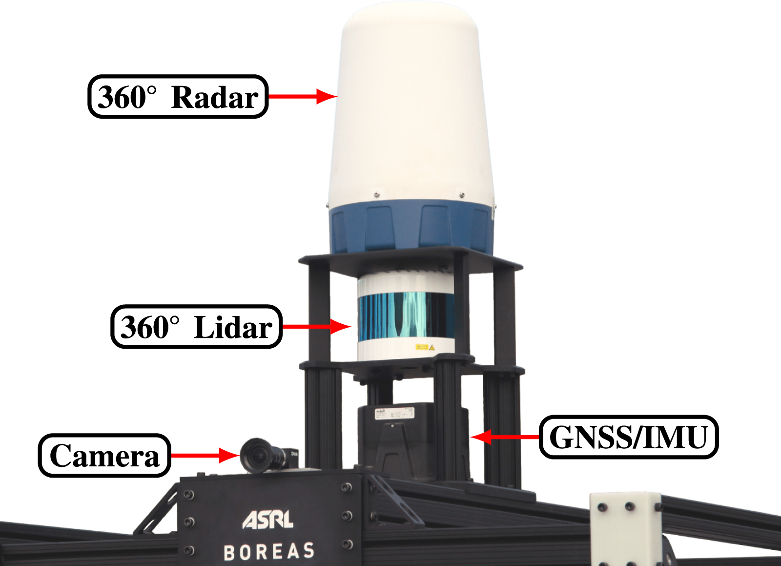
To encourage research in this area, we have created the Boreas dataset, a large multi-modal dataset collected by driving a repeated route over the course of 1 year. The dataset features over 350 km of driving data with stark seasonal variations and multiple sequences with adverse weather such as rain and falling snow. Our data-taking platform, shown in Figure 1, includes a 128-beam lidar, a 5 MP camera, and a 360° scanning radar. Globally consistent centimetre-accurate ground truth poses are obtained by post-processing global navigation satellite system (GNSS), inertial measurement unit (IMU), and wheel encoder data along with a secondary correction subscription. Our dataset will support benchmarks for odometry, metric localization, and 3D object detection. Our platform, Boreas, includes a Velodyne Alpha-Prime (128-beam) lidar, a FLIR Blackfly S camera, a Navtech CIR304-H radar, and an Applanix POS LV GNSS-INS.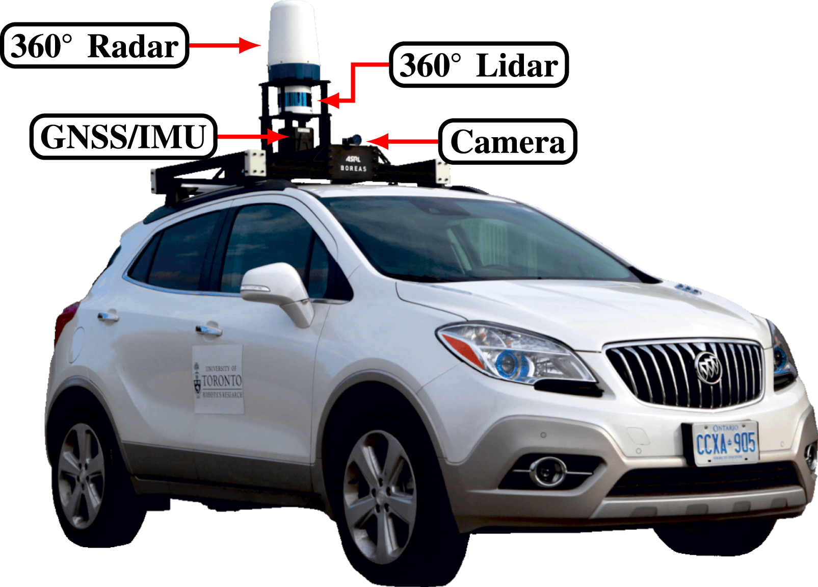
This dataset may be used to study the effects of seasonal variation on long-term localization. Further, this dataset enables comparisons of vision, lidar, and radar-based mapping and localization pipelines. Comparisons may include the robustness of individual sensing modalities to adverse weather or the resistance to map degradation.
The main contributions of this dataset are as follows: • Data collected on a repeated route over the course of 1 year including multiple weather conditions. • A unique, high-quality sensor configuration including a 128-beam lidar and 360° radar. • Post-processed GNSS/IMU data to provide accurate ground truth pose information. • A live and open leaderboard for odometry, metric localization, and 3D object detection. • 3D object labels collected in sunny weather.
2. Related work
Many of the published autonomous driving datasets focus on perception, particularly 3D object detection and semantic segmentation of images and lidar pointclouds. However, these datasets tend to lack variation in weather and season. Further, many of these datasets do not provide radar data. Automotive radar sensors are robust to precipitation, dust, and fog thanks to their longer wavelength. For this reason, radar may play a key role in enabling autonomous vehicles to operate in adverse weather. The Boreas dataset addresses these shortcomings by including a 360° scanning radar, and data taken during various weather conditions (sun, cloud, rain, night, and snow) and seasons.
Related datasets. Lead: public leaderboard. Size: For perception datasets, size is given as the number of annotated frames and the number of annotations (3D boxes).
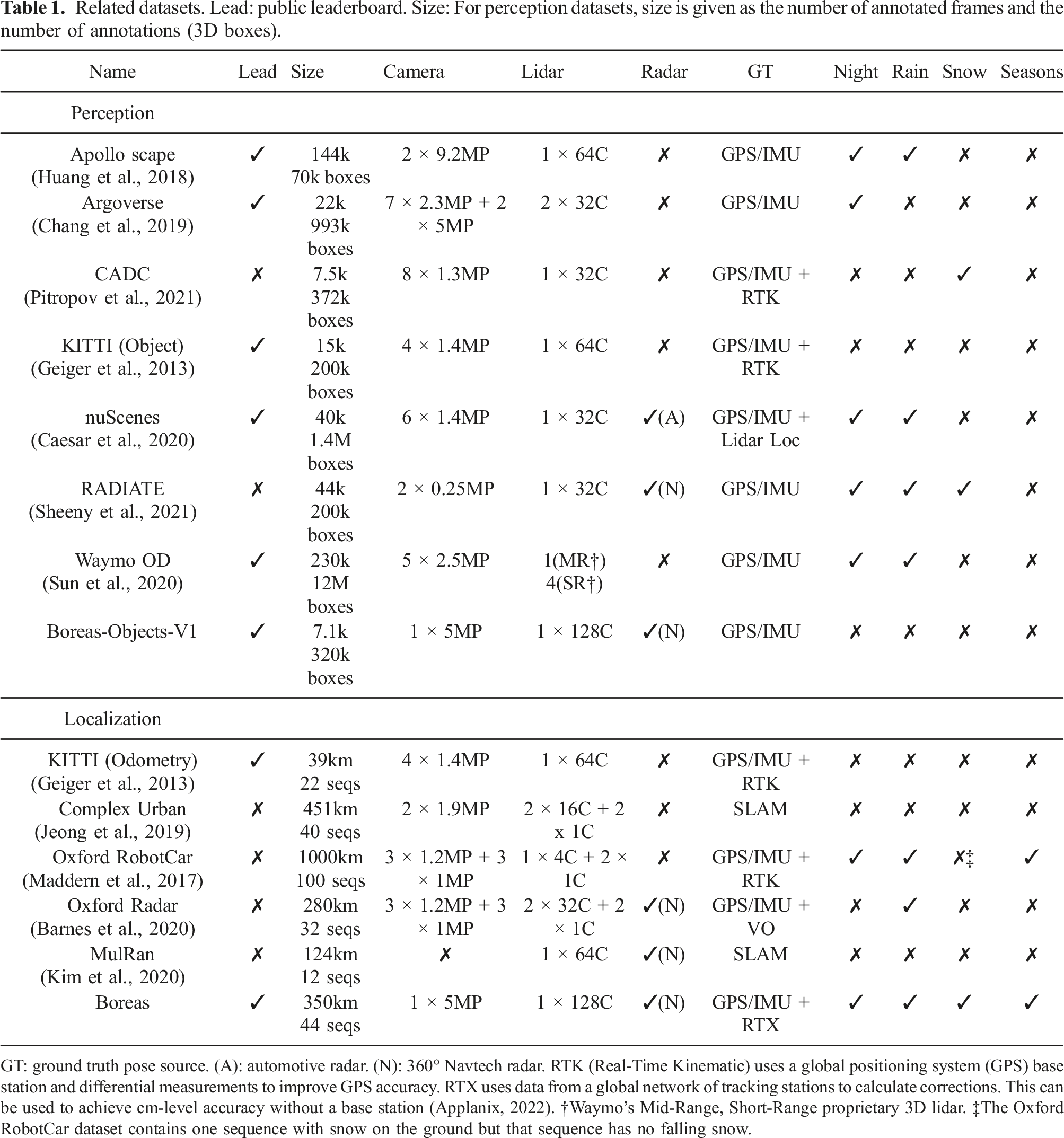
GT: ground truth pose source. (A): automotive radar. (N): 360° Navtech radar. RTK (Real-Time Kinematic) uses a global positioning system (GPS) base station and differential measurements to improve GPS accuracy. RTX uses data from a global network of tracking stations to calculate corrections. This can be used to achieve cm-level accuracy without a base station (Applanix, 2022). †Waymo’s Mid-Range, Short-Range proprietary 3D lidar. ‡The Oxford RobotCar dataset contains one sequence with snow on the ground but that sequence has no falling snow.
3. Data collection
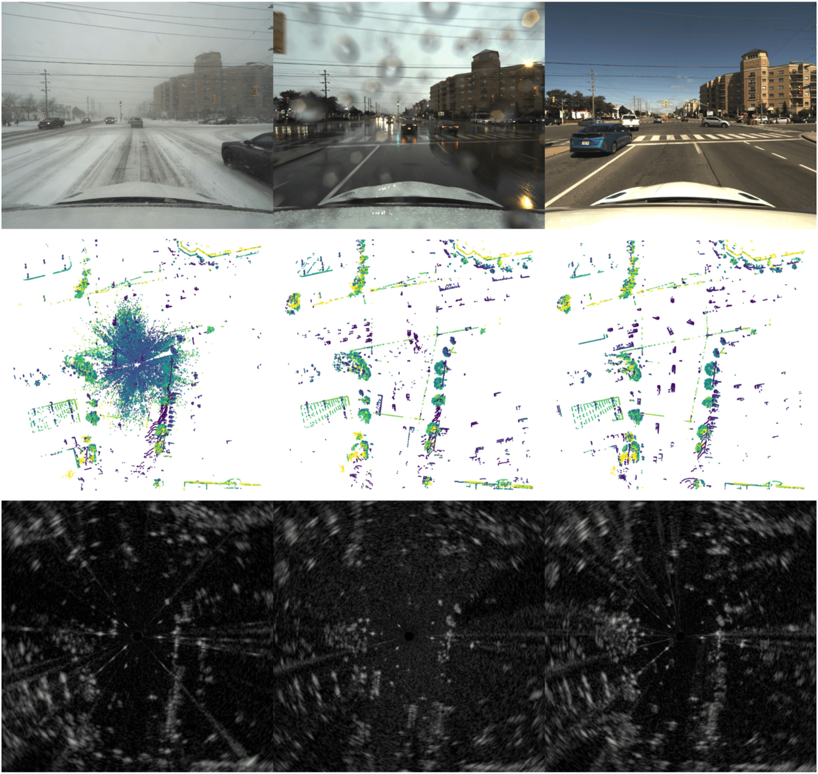
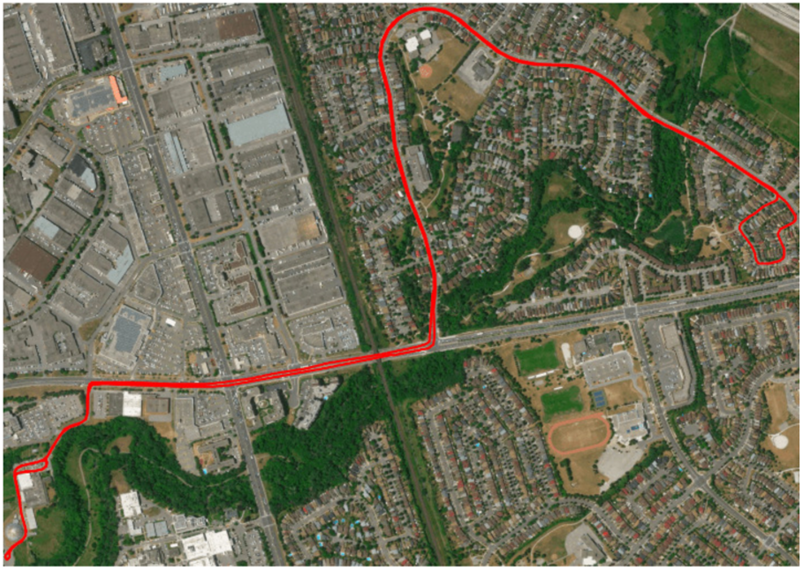
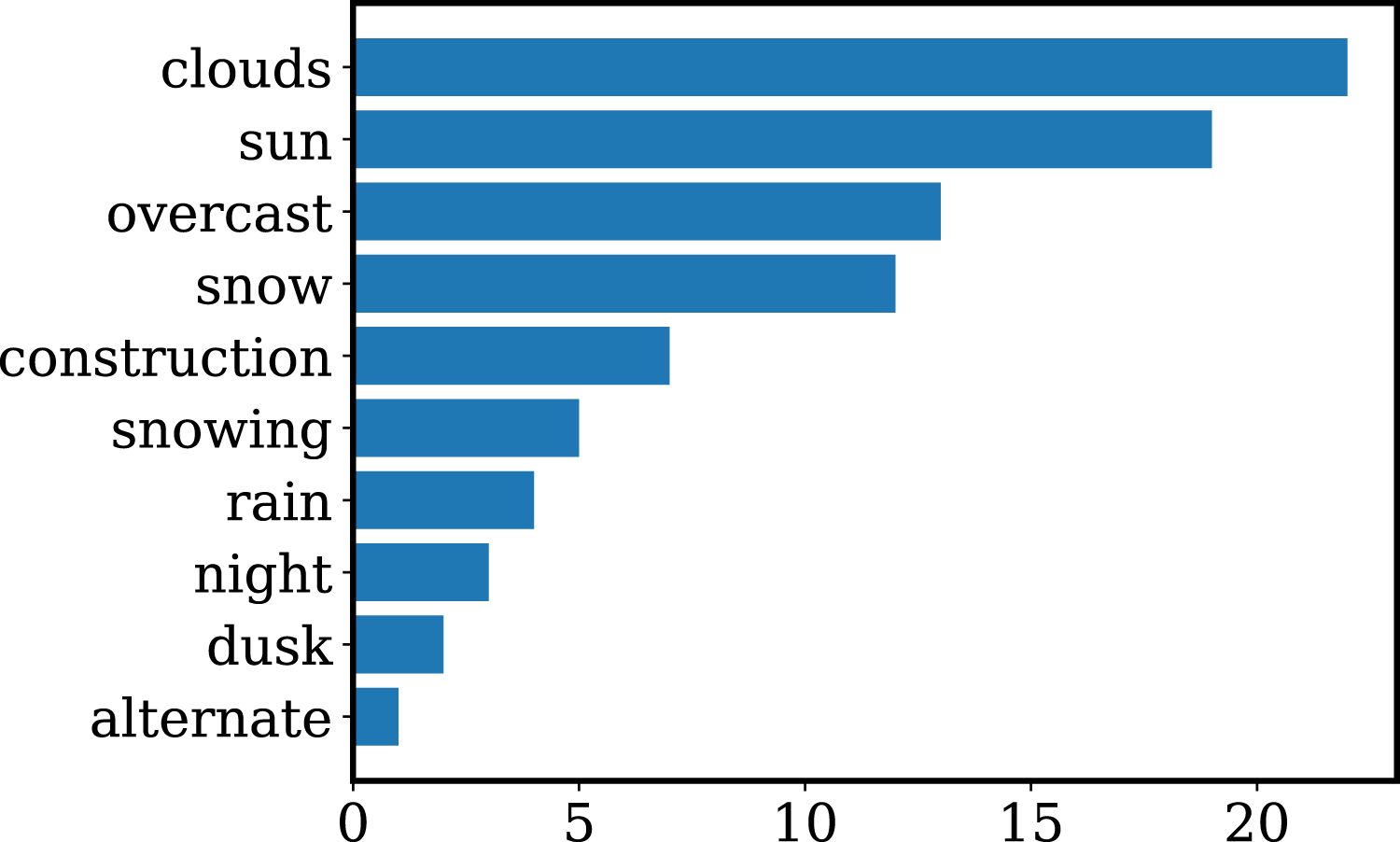
The majority of the Boreas dataset was collected by driving a repeated route near the University of Toronto over the course of 1 year. Figure 2 illustrates the seasonal variations that were observed over this time. Figure 3 compares camera, lidar, and radar measurements in three distinct weather conditions: falling snow, rain, and sun. The primary repeated route will be referred to as the Glen Shields route and is depicted in Figure 4. Additional routes were also collected as either a single standalone sequence or a small number of repeated traversals. The Glen Shields route can be used for research related to long-term localization while the other routes allow for experiments that test for generalization to previously unseen environments. The frequency of different metadata tags is displayed in Figure 5. This figure depicts 1 year of seasonal changes in the Boreas dataset. Each image represents a camera image that was taken on a different day. The sequences are sorted in chronological order from left to right and top to bottom, starting in November 2020 and finishing in November 2021. Note that the sequences are not evenly spaced in time. Weather variation in the Boreas dataset. Note that the lidar pointcloud becomes littered with detections associated with snowflakes during falling snow and that the radar data remains relatively unperturbed across the weather conditions. The Glen Shields route in Toronto, Ontario, Canada. Mapbox satellite data was used to generate this figure. Frequency of metadata tags in the Boreas dataset. Snow: snow is on the ground, snowing: it is actively snowing, alternate: a route other than Glen Shields.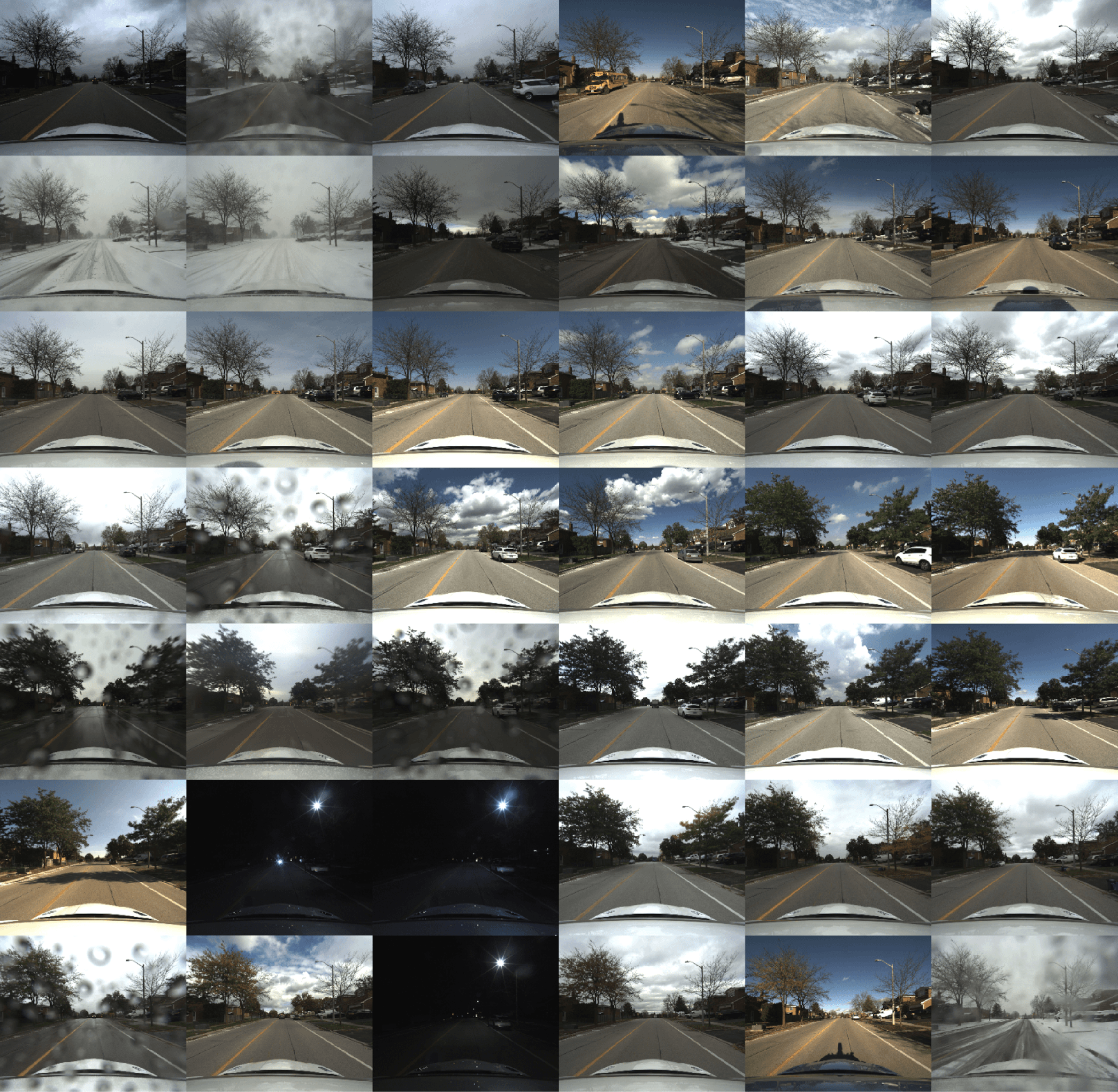
4. Sensors
Sensor specifications.
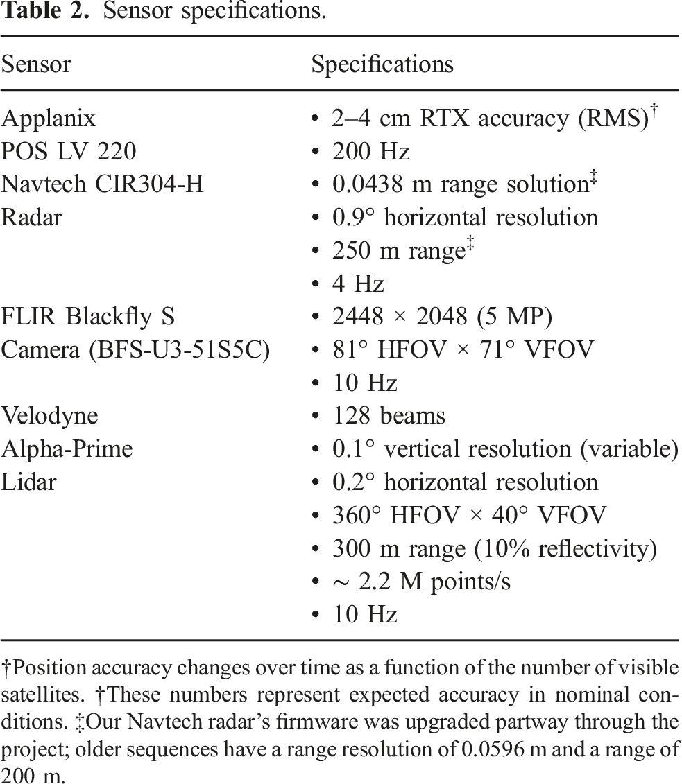
†Position accuracy changes over time as a function of the number of visible satellites. †These numbers represent expected accuracy in nominal conditions. ‡Our Navtech radar’s firmware was upgraded partway through the project; older sequences have a range resolution of 0.0596 m and a range of 200 m.
A close-up view of Boreas’ sensor configuration.
Boreas sensor placement. Distances are given in metres. Measurements shown are approximate. Refer to the calibrated extrinsics contained in the dataset for precise measurements.
5. Dataset format
5.1. Data organization
The Boreas dataset is divided into sequences, which include all sensor data and ground truth poses from a single drive. Sequences are identified by the date and time at which they were collected with the format Data organization for a single Boreas sequence.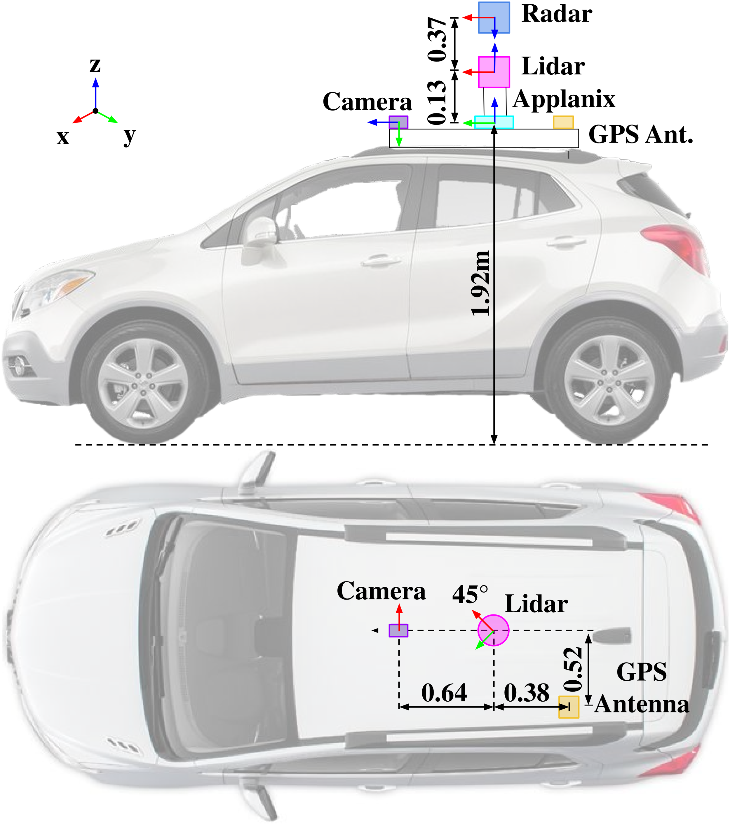
5.2. Timestamps
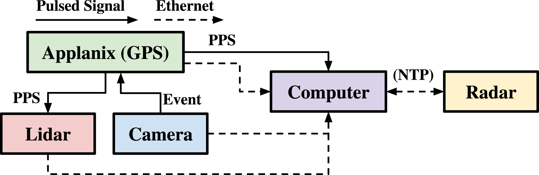
The name of each file corresponds to its timestamp. These timestamps are given as UNIX epoch times in microseconds. All sensor timestamps were synchronized to the coordinated universal time (UTC) time reported by the Applanix POS LV. The Velodyne lidar was synchronized using a standard hardwired connection to the Applanix POS LV carrying a pulse-per-second (PPS) signal and NMEA messages. The camera was configured to emit a square-wave pulse where the rising edge of each pulse corresponds with the start of a new camera exposure event. The Applanix POS LV was then configured to receive and timestamp these event signals. Camera timestamps were then corrected in post using the recorded event times and exposure values: tcamera = tevent + ½exposure(tevent).
The data-recording computer was synchronized to UTC time in a fashion similar to the Velodyne, using an RS-232 serial cable carrying a PPS signal and NMEA messages. The Navtech radar synchronizes its local clock using network time protocol (NTP). Since the data-recording computer publishing the NTP time is synchronized to UTC time, the radar is thereby also synchronized to UTC time.
For lidar pointclouds, the timestamp corresponds to the temporal middle of the scan. Each lidar point also has a timestamp associated with it. These point times are given in seconds relative to the middle of the scan. For radar scans, the timestamp also corresponds to the middle of the scan: ⌊M/2⌋ − 1 where M is the number of azimuths. Each scanned radar azimuth is also timestamped in the same format as the filename, a UNIX epoch time. A diagram of our synchronization setup is shown in Figure 9. Time synchronization of sensors on Boreas.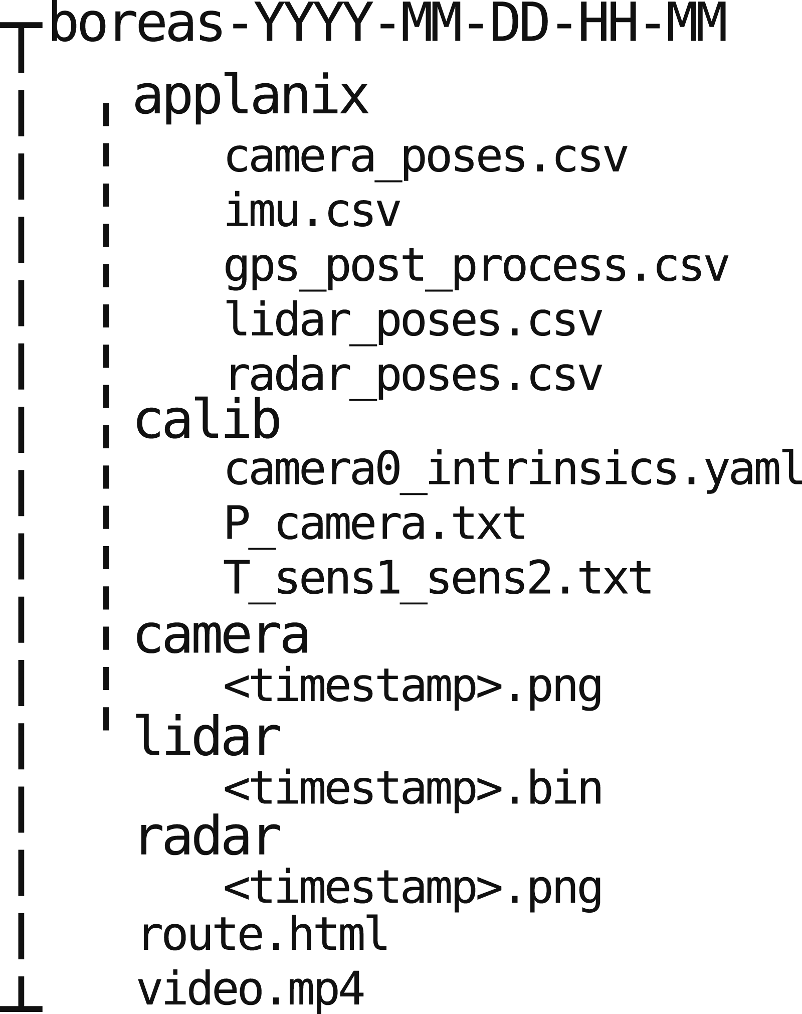
5.3. File formats
Camera images are rectified and anonymized by default. We use Anonymizer to blur license plates and faces (Understand, 2022). Images are stored in the commonly used png format. Lidar pointclouds are stored in a binary format to minimize storage requirements. Our devkit provides methods for working with these binary formats in both C++ and Python. Each point has six fields: [x, y, z, i, r, t] where (x, y, z) is the position of the point with respect to the lidar, i is the intensity of the reflected infrared signal, r is the ID of the laser that made the measurement, and t the point timestamp explained in Section 5.2. Raw radar scans are stored as 2D polar images: M azimuths × R range bins. We follow Oxford’s convention and embed timestamp and encoder information into the first 11 columns (bytes) of each polar radar scan. The first eight columns represent a 64-bit integer, the UNIX epoch timestamp of each azimuth in microseconds. The next two columns represent a 16-bit unsigned integer, the rotational encoder value. The next column is unused but preserved for compatibility with the Oxford format (see Barnes et al. (2020) for further details on the Navtech sensor and this file format). The polar radar scans can be readily converted into a top-down Cartesian representation, as shown in Figure 3, using our devkit.
Note that measurements are not synchronous as in other datasets (KITTI and CADC), which means that measurements with the same index do not have the same timestamp. However, given the timestamps and relative pose information, different sensor measurements can still be fused together. Lidar pointclouds are not motion-corrected, but we do provide methods for removing motion distortion in our devkit. Navtech radar scans suffer from both motion distortion and Doppler distortion. Burnett et al. (2021a) and Burnett et al. (2021b) provide methods to compensate for these effects.
6. Ground truth poses
Ground truth poses are obtained by post-processing GNSS, IMU, and wheel encoder measurements along with corrections obtained from an RTX subscription using Applanix’s POSPac software suite. Positions and velocities are given with respect to a fixed East-North-Up frame ENUref. The position of ENUref is aligned with the first pose of the first sequence
The residual root mean square (RMS) position error reported by Applanix is typically less than 5 cm in nominal conditions but can be as high as 20–40 cm in urban canyons. Figure 10 shows the residual RMS errors resulting from the post-processing conducting by the Applanix POSPac software. The estimated error can change depending on the visibility of satellites. Note that these values represent global estimates and that relative pose estimates are more accurate over short time horizons. Post-processed RMS position, velocity, and orientation residual error versus time reported by Applanix’s POSPac software for a sequence collected on 2021-09-07.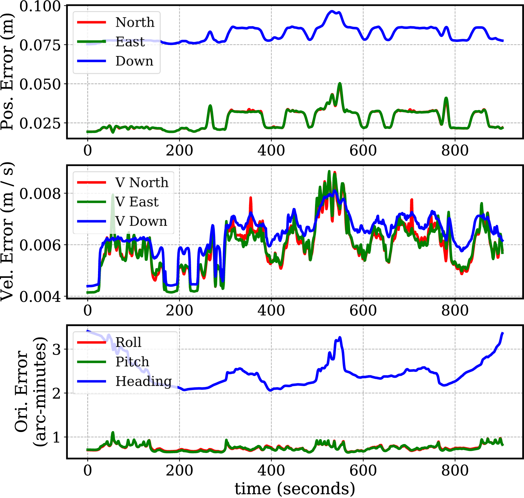
7. Calibration
7.1. Camera intrinsics
Camera intrinsics are calibrated using MATLAB’s camera calibrator (Mathworks, 2022) and are recorded in 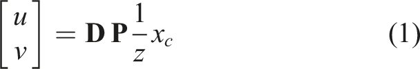
7.2. Sensor extrinsics
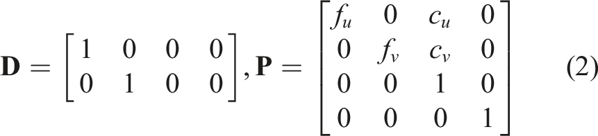
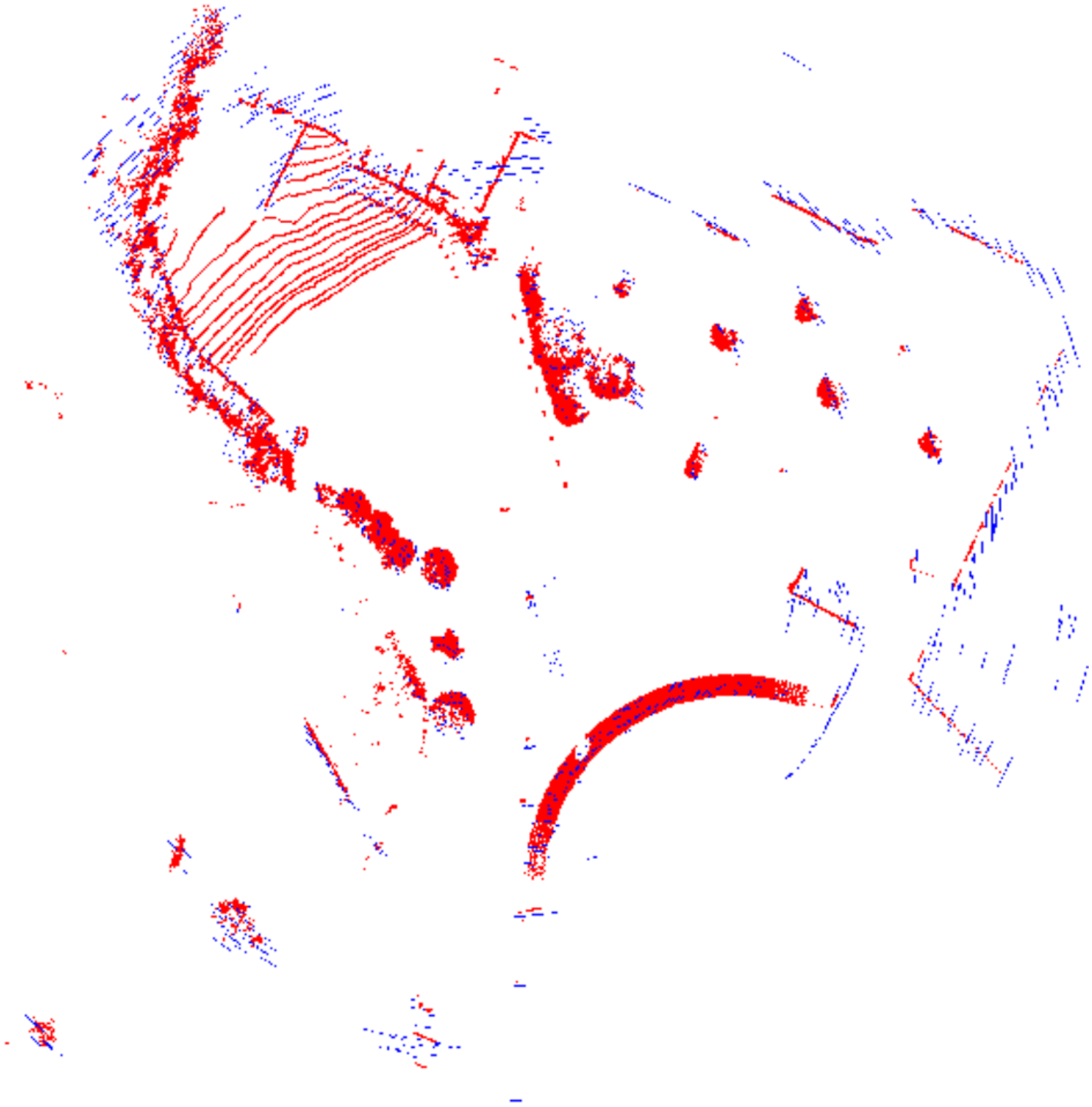
The extrinsic calibration between the camera and lidar is obtained using MATLAB’s camera to lidar calibrator (Mathworks, 2022). The results of this calibration are illustrated in Figure 11. To calibrate the rotation between the lidar and radar, we use correlative scan matching via the Fourier Mellin transform (Checchin et al., 2010). Several lidar–radar pairs were collected while the vehicle was stationary at different locations. The final rotation estimate is obtained by averaging the results from several measurement pairs (Burnett, 2020). The translation between the lidar and radar is obtained from the computer assisted design (CAD) model of the roof rack. The results of the radar-to-lidar calibration are shown in Figure 12. The extrinsics between the lidar and the Applanix reference frame were obtained using Applanix’s in-house calibration tools. Their tool outputs this relative transform as a by-product of a batch optimization aiming to estimate the most likely vehicle path given a sequence of lidar pointclouds and post-processed GNSS/IMU measurements. All extrinsic calibrations are provided as 4 × 4 homogeneous transformation matrices under the Lidar points projected onto a camera image using the camera–lidar calibration. (a) Lidar points are coloured based on their longitudinal distance from the vehicle. (b) Lidar points are given RGB colour values based on their projected location on the camera image. Lidar measurements are drawn in red using a bird’s eye view projection with the ground plane removed. Radar targets are first extracted from the raw radar data and then are drawn as blue pixels. The two sensors have been aligned using the radar-to-lidar calibration.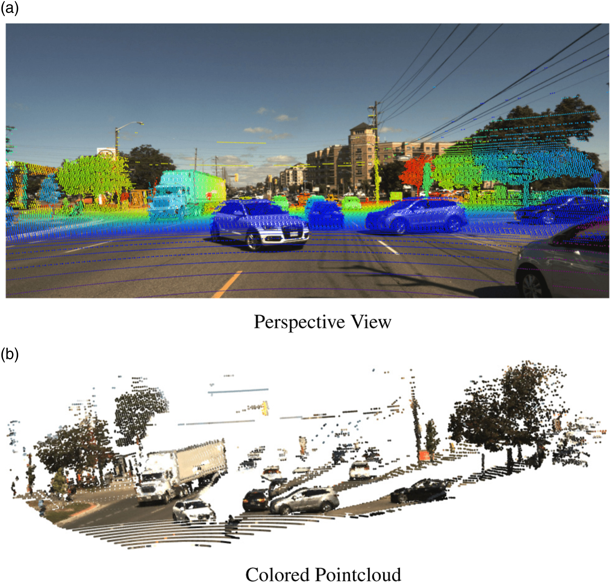
8. 3D Annotations
We provide a set of 3D bounding box annotations for a subset of the Boreas dataset, obtained in sunny weather. We refer to this as the Boreas-Objects-V1 dataset. Annotations were obtained using the Scale.ai data annotation service (Scale, 2022). In total, 7111 lidar frames were annotated at 5 Hz, resulting in 326,180 unique 3D box annotations. Since the lidar data was collected at 10 Hz, the annotations may be interpolated between frames to double the number of annotated frames at a slightly lower fidelity. The data is divided into 53 continuous scenes where each scene is 20–70 s in duration. The scenes are then divided into 37 training scenes and 16 test scenes where the ground truth labels have been withheld for the benchmark. Figure 13 displays two statistics for our annotations. 3D annotation statistics for Boreas-Objects-V1.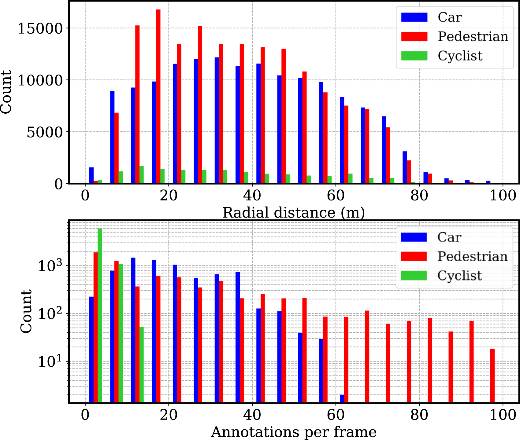
We use the same folder structure as in Figure 8 but with an additional folder, Examples of 3D annotations in the Boreas-Objects-V1 dataset.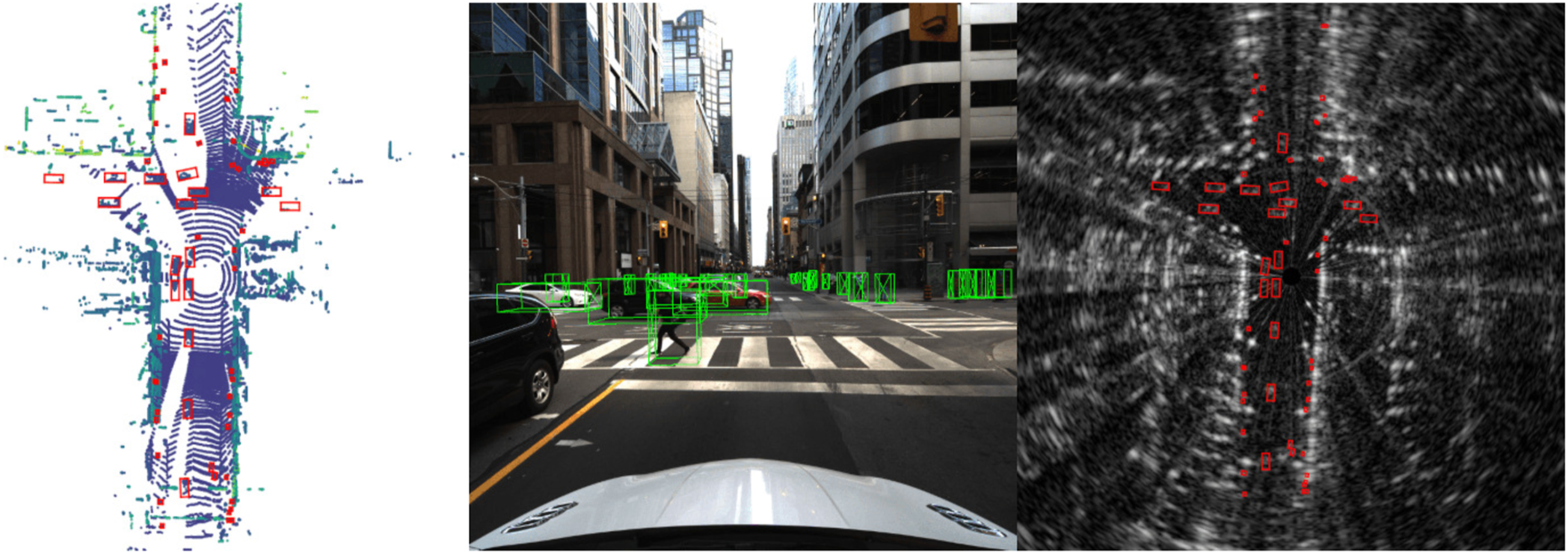
9. Benchmark metrics
At launch, we plan to support online leaderboards for odometry, metric localization, and 3D object detection. For odometry, we use the same metrics as the KITTI dataset (Geiger et al., 2013). The KITTI odometry metrics average the relative position and orientation errors over every sub-sequence of length (100 m, 200 m, 300 m, …, 800 m). This results in two metrics, a translational drift reported as a percentage of path length and a rotational drift reported as degrees per metre travelled. For 3D object detection, we also defer to the KITTI dataset by reporting the mean average precision (mAP) on a per-class basis. For cars, a 70% overlap counts as a true positive, and for pedestrians, 50%. These ratios are used as they are the same as what was used in the KITTI dataset. We do not divide our dataset based on difficulty levels.
The purpose of our metric localization leaderboard is to benchmark mapping and localization pipelines. In this scenario, we envision a situation where one or more repeated traversals of the Glen Shields route are used to construct a map offline. Any and all data from the training sequences may be used to construct a map in any fashion.
Then, during a test sequence, the goal is to perform metric localization between the live sensor data and the pre-built map. Localization approaches may make use of temporal filtering and can leverage the IMU if desired, but GNSS information will not be available. The goal of this benchmark is to simulate localizing a vehicle in real time and as such methods may not use future sensor information in an acausal manner.
Our goal is to support both global and relative map structures. Only one of the training sequences will be specified as the map sequence used by the benchmark. For 3D localization, users must choose either the lidar or camera as the reference sensor. For 2D localization, only the radar frames are used as a reference. For each (camera–lidar–radar) frame s2 in the test sequence, users will specify the ID (timestamp) of the (camera–lidar–radar) frame s1 in the map sequence that they are providing a relative pose with respect to: 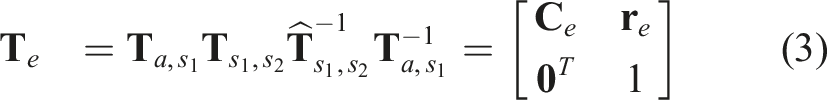

Users will also have the option of providing 6 × 6 covariance matrices 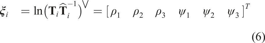
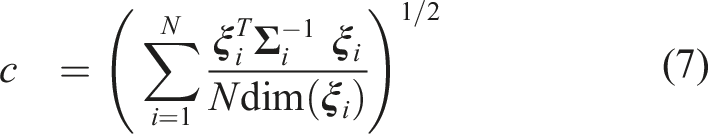
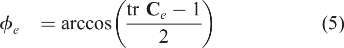
A consistency score close to 1 is ideal. c < 1 means that the method is over-confident and c > 1 means that the method is conservative. Note that the above metrics will be averaged across the test sequences.
10. Development kit
As part of this dataset, we provide a development kit for new users to get started. The primary purpose of the devkit is to act as a wrapper around the dataset to be used in Python. This allows users to query frames and the associated ground truth for either odometry, localization, or 3D object detection. We also provide convenience methods for removing motion distortion from pointclouds, working with polar radar scans, and converting to and from Lie algebra and Lie group representations. The devkit also provides several ways to visualize sensor data. We also provide introductory tutorials in Jupyter notebooks that include projecting lidar onto a camera frame and visualizing 3D boxes. Evaluation scripts used by our benchmark will be stored in the devkit, allowing users to validate their algorithms before submission to the benchmark. The development kit can be found at boreas.utias.utoronto.ca.
11. Conclusion
In this paper, we presented Boreas, a multi-season autonomous driving dataset that includes over 350 km of driving data collected over the course of 1 year. The dataset provides a unique high-quality sensor suite including a Velodyne Alpha-Prime (128-beam) lidar, a 5MP camera, a 360° Navtech radar, and accurate ground truth poses obtained from an Applanix POS LV with an RTX subscription. We also provide 3D object labels for a subset of the Boreas data obtained in sunny weather. The primary purpose of this dataset is to enable further research into long-term localization across seasons and adverse weather conditions. Our website will provide an online leaderboard for odometry, metric localization, and 3D object detection.
Footnotes
Acknowledgements
We would like to thank Goran Basic for his help in designing and assembling the roof rack for Boreas. We also thank General Motors for their donation of the Buick vehicle. The Amazon Open Data Sponsorship program supports this project by hosting the Boreas dataset.
Declaration of conflicting interests
The author(s) declared no potential conflicts of interest with respect to the research, authorship, and/or publication of this article.
Funding
The author(s) received no financial support for the research, authorship, and/or publication of this article.