
Abstract
Cables are complex, high-dimensional, and dynamic objects. Standard approaches to manipulate them often rely on conservative strategies that involve long series of very slow and incremental deformations, or various mechanical fixtures such as clamps, pins, or rings. We are interested in manipulating freely moving cables, in real time, with a pair of robotic grippers, and with no added mechanical constraints. The main contribution of this paper is a perception and control framework that moves in that direction, and uses real-time tactile feedback to accomplish the task of following a dangling cable. The approach relies on a vision-based tactile sensor, GelSight, that estimates the pose of the cable in the grip, and the friction forces during cable sliding. We achieve the behavior by combining two tactile-based controllers: (1) cable grip controller, where a PD controller combined with a leaky integrator regulates the gripping force to maintain the frictional sliding forces close to a suitable value; and (2) cable pose controller, where an linear–quadratic regulator controller based on a learned linear model of the cable sliding dynamics keeps the cable centered and aligned on the fingertips to prevent the cable from falling from the grip. This behavior is possible with the use of reactive gripper fitted with GelSight-based high-resolution tactile sensors. The robot can follow 1 m of cable in random configurations within two to three hand regrasps, adapting to cables of different materials and thicknesses. We demonstrate a robot grasping a headphone cable, sliding the fingers to the jack connector, and inserting it. To the best of the authors’ knowledge, this is the first implementation of real-time cable following without the aid of mechanical fixtures. Videos are available at http://gelsight.csail.mit.edu/cable/
Keywords
1. Introduction
Contour following is a dexterous skill which can be guided by tactile servoing. A common type of contour following occurs with deformable linear objects (DLOs), such as cables. After grasping a cable loosely between the thumb and forefinger, one can slide the fingers to a target position as a robust strategy to regrasp it. For example, when trying to find the plug-end of a loose headphone cable, one may slide along the cable until the plug is felt between the fingers.
Cable following is challenging because the cable’s shape changes dynamically with the sliding motion, and there are unpredictable factors such as kinks, variable friction, and external forces. For this reason, much work on cables (and other DLOs) has utilized mechanical constraints (Nair et al., 2017; Yan et al., 2019; Zhu et al., 2018). For example a rope may be placed on a table, so that gravity and friction yield a quasistatic configuration of the cable. A gripper can then adjust the rope configuration, step by step, at a chosen pace.
Our goal is to manipulate cables in real time, using a pair of grippers, with no added mechanical constraints. The cables are free to wiggle, swing, or twist, and our grippers must rapidly react using tactile feedback. In particular, we look at the task of picking one end of a cable with a gripper and following it to the other end with a second gripper, as shown in Figure 1.
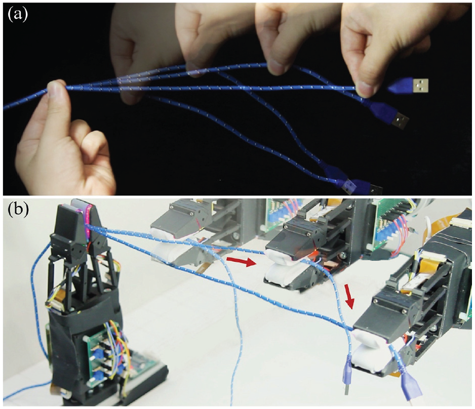
Following a cable with (a) human hands and (b) robotic grippers.
We designed a novel gripper that is lightweight and fast reacting, and equipped it with high-resolution tactile sensors. This novel hardware, when paired with appropriate control policies, allows us to perform real-time cable following in free space.
In this paper, we do not use vision, relying on tactile sensing alone. While vision can be helpful, we are able to perform the task purely with tactile guidance. DLOs are easily occluded from view by grippers, by the environment, and often by itself. Tactile perception allows for precise localization once the cable is grasped. Tactile active perception, such as when pulling from the two ends of a cable until it is in tension, can also be used to simplify perception such as in the case of a tangled rope.
We approach cable following by dividing the desired behavior into two goals: (1) cable grip control, which monitors the gripping force to maintain friction forces within a useful range; and (2) cable pose control, which regulates the configuration of the cable to be centered and aligned with the fingers. These two controllers work in tandem to enable smooth and efficient cable sliding. The first controller maintains the frictional interaction between cable and fingers near a desired working point, which simplifies the dynamics that the cable pose controller has to regulate. To accomplish this task, we build a system with the following modules.
We evaluate the complete system in the task of cable following for various cables, sliding at different velocities, and benchmark against several baseline algorithms. The results in Section 6 show that training the system on a single cable type allows generalization to a range of cables with other physical parameters. Finally, we demonstrate a robot picking a headphone cable, sliding the fingers until feeling the jack connector, and inserting it, illustrating the potential role of the system in complex active perception and manipulation tasks. Video demonstrations of the aforementioned tasks are available on the project website at http://gelsight.csail.mit.edu/cable/.
2. Related work
In this section, we review work relevant to contour following and cable manipulation.
2.1. Contour following
Contour following of rigid objects has been widely studied using both visual (Lange et al., 1998) and tactile perception (Chen et al., 1995; Ward-Cherrier et al., 2018). These techniques do not directly translate to deformable objects due to dynamic shape changes that are difficult to model, especially in real time.
The most similar contour following work to ours is by Hellman et al. (2017), who proposed a reinforcement learning approach to close a deformable ziplock bag with feedback from BioTac sensors. The work demonstrated a robot grasping and following the edge of the bag. In contrast to our approach, they use a constant grasping force and discrete slow actions. As a consequence, they achieve a maximum speed of 0.5 cm/s, compared with 6.5 cm/s in our work.
2.2. Cable/rope manipulation
Manipulating DLOs has attracted attention in the robotics community (Hopcroft et al., 1991) with tasks including tying knots (Morita et al., 2003; Saha et al., 2008), untangling (Grannen et al., 2020; Lui and Saxena, 2013), insertion (Wang et al., 2015), reshaping (Nair et al., 2017; Yan et al., 2019; Zhu et al., 2018), surgical suturing (Mayer et al., 2008), or dynamic rope manipulation (Yamakawa et al., 2010; Zhang et al., 2010). Our approach to cable manipulation through tactile perception and control is fundamentally distinct from the existing literature and enables a larger potential action space.
2.2.1. Approaches
Much of the classical work in DLO manipulation involves perceiving the state of the DLO, simulating the dynamics of the DLO, or planning its motion. Visual perception for DLO state estimation is difficult given the infinite-dimensional configuration space with the object’s shape dynamically changing while often being occluded. Morita et al. (2003) described rope state topologically by listing intersections created by rope crossings. Methods that more completely describe location along the entire length of the DLO often use non-rigid registration techniques to track the rope from a known initial state (Chi and Berenson, 2019; Tang et al., 2017). Alternatively, an initial state estimate from a given point cloud can be refined to better align with the system dynamics (Javdani et al., 2011; Lui and Saxena, 2013).
The most common methods for simulating DLOs use mass–spring models (Wang et al., 2005), energy minimization (Bergou et al., 2008), or finite-element methods (FEM) (Petit et al., 2015). These models can be computationally expensive and require knowledge of the DLO’s physical properties such as rigidity, elasticity, and friction. Berenson (2013) avoids an explicit deformable object model by using an approximation to the Jacobian of the deformable object to drive object points to a target set. Work by Yamakawa et al. (2012) also avoids complicated dynamics models by moving the cables at high enough speeds that they assume each rope segment follows the motion of the robot with a constant time delay.
Motion planning for DLOs has traditionally used sampling-based approaches such as a probabilistic roadmap (PRM) (Kavraki et al., 1996) or Rapidly-exploring Random Trees (RRTs) (LaValle, 1998). Moll and Kavraki (2006) used these methods to create local planners based on minimum energy curves. For knot-tying, Saha et al. (2008) planned long-horizon, complex motions by simulating deformations of a rope in response to random external forces and placing configurations that would be part of the knot’s topological forming sequence in a PRM.
Learning-based approaches can help simplify aspects of the problem. Given the inherent difficulty of complete state estimation, some DLO manipulation works are trained directly from visual data without estimating state (list including dense knot paper, 2021). Nair et al. (2017) learned a pixel-level inverse dynamics model for a rope with self-supervised autonomous pick-and-place interactions. More recently, sundaresan2020dense (2020) and ganapathi2020mmgsd (2020) used dense object descriptors to find pixel-wise correlations between images of ropes trained in simulation. Another class of work learns dynamics models for rope and uses them with model predictive control (MPC). Work by interaction (2021) extends interaction networks to learn dynamics models, and ebertforesight (2018) learned a video prediction model. While these methods work for short-horizon tasks such as shaping, planning for more complex, long-horizon tasks such as tying knots requires more guidance, for example learning from demonstration (lfd papers, 2021). While these data-driven methods allow for faster computation, they are less generalizable for other DLO manipulation tasks.
2.2.2. Rope manipulation skills
Owing to their high-dimensional dynamics, manipulating DLOs is usually simplified by constraining their motion with external features, for example against a table (Nair et al., 2017; Yan et al., 2019; Zhu et al., 2018), with additional grippers (Mayer et al., 2008), or pegs (Saha et al., 2008). Another common strategy involves limiting movements to long series of small deformations with pick and place actions (Nair et al., 2017; Yan et al., 2019). Thus, the dynamics of the system can be treated as quasistatic.
Furthermore, the action space in DLO manipulation literature is generally limited to those using fixed grasps of the DLO. In addition to pick and place, other actions include following specific, potentially dynamic, trajectories (Yamakawa et al., 2010), moving a segment of a rope using two grippers (McConachie et al., 2020), insertion (Wang et al., 2015), and wrapping (Zhu et al., 2019).
Few works exploit sliding along the DLO. Zhu et al. (2019) routed a cable around pegs using one end-effector that was attached to the cable end and another fixed end-effector that would passively let a cable slip through in order to pull out a longer length of cable. This system, while allowing for sliding, loses the ability to sense and control the state of the cable at the sliding end, which can be in contact with any point of the cable.
Jiang et al. (2015) traced cables in a wire harness using a gripper with rollers in the jaws. This gripper passively adjusts grip force using springs to accommodate different sized cables. They sense and control the force perpendicular to the translational motion along the cable in order to follow the cable. The cables in our work are considerably smaller and less rigid, so such forces would be difficult to sense.
Furthermore, both of the specialized, passive end-effectors in these two works have limited capabilities beyond sliding along the cable. In our work, the parallel jaw gripper used to follow a cable is also used to insert the cable into a headphone jack, demonstrating the potential of this hardware setup for additional tasks.
Another example of work involving sliding with rope from Yamakawa et al. (2007) shows how our framework could potentially be extended for the knot-tying task. To pass one end of the rope through a loop, they leverage tactile sensing to roll the two rope ends relative to each other in between the fingers.
2.3. Cloth manipulation skills
A further suggestion of generality of the approach is the potential use of sliding in fabric manipulation. Most work in fabric manipulation similarly uses the quasistatic assumption and incremental pick-and-place movements (Ganapathi et al., 2020; Hoque et al., 2020; Wu et al., 2019). However, the sliding skill simplifies the task of finding two adjacent corners in order to fold a piece of fabric. Sahari et al. (2010) holds up a corner of the fabric and uses gravity to trace straight down to find the second corner without sensory feedback. Similarly, Yuba et al. (2017) executes a “pinch and slide” motion along the top edge of a piece of fabric.
In addition to the knotting example from Yamakawa et al. (2007), force and tactile sensors can be seen in a variety of rope manipulation literature. Abegg et al. (2000) uses a force torque sensor to detect changes in contact state, for example the rope moving from free space to contacting an edge of a rigid object. Yue and Henrich (2002) detects vibration frequency of a rope using a force torque sensor before counteracting the vibration.
2.4. Vision-based tactile sensor
The vision-based tactile sensor converts touch to vision by using a camera to visualize the deformation of the contact surface. With its high spatial resolution, this type of sensor shows unique advantages and has been successfully utilized in different robotic manipulation tasks, for instance, contour following (Lepora et al., 2019), cutting (Yamaguchi and Atkeson, 2016), dish loading (Kuppuswamy et al., 2020), and in-hand manipulation (Lambeta et al., 2020).
As a popular vision-based tactile sensor, the GelSight sensor (Yuan et al., 2017) can recover a precise depth map of the contact surface with designed three light illumination. The measured high-resolution local contact geometry can be used to estimate the object state. Here we use it to estimate the pose of the cable in hand. Figure 2 shows an example of the sensor raw output and recovered depth image when grasping a cable. The sensor also measures approximate shear force by tracking the black markers on the sensor surface (Yuan et al., 2015). Here we use it to estimate the approximated friction force during cable sliding.
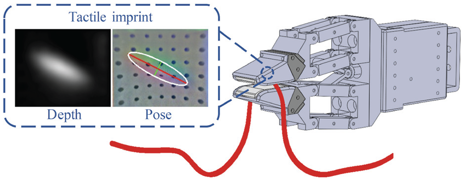
The design concept of the cable manipulation system.
The GelSight sensor has been applied extensively in various manipulation problems. Li et al. (2014a) implemented a USB insertion task from random grasping poses based on object pose estimation feedback from the sensor. Izatt et al. (2017a) used the 3D point cloud from GelSight sensor in a Kalman filter to better register the position of a screwdriver in a peg-in-hole task. Calandra et al. (2018) and Hogan et al. (2018) used the tactile images to evaluate the quality of a grasp and further infer better regrasp positions. Dong et al. (2018) used the sensor to predict slip and used it slip signal to modulate grasping forces while conducting a bottle cap screwing task. Tian et al. (2019) proposed a tactile-based MPC method to reposition an object. Dong and Rodriguez (2019) trained a tactile-based object insertion policy that could correct small misalignment between the object and the environment. Hogan et al. (2020) designed closed-loop tactile controllers for dexterous table-top manipulation with dual-arm robotic palms, where an idea similar to our method of simultaneously controlling contact state and object state was adopted. Wang et al. (2020) implemented a task of swing an elongated object to a target pose based on the learned friction, center of mass properties of the grasp object with the GelSight sensor.
3. Tasks
3.1. Cable following
The goal of the cable-following task is to use a robot gripper to grip the beginning of the cable with proper force and then control the gripper to follow the cable contour all the way to its tail end. The beginning end of the cable is initially firmly gripped by another fixed gripper during the cable-following process. The moving gripper is allowed to regrasp the cable by bringing it back to the fixed gripper, resulting in two-hand coordination with one of the hands fixed. Several cables with different properties (shape, stiffness, surface roughness) are tested here for generalization.
3.2. Cable insertion
The goal of the cable insertion task is to find the plug at the end of a cable and insert the plug into the socket. We show that this can be done by leveraging the ability to slide the fingers on the cable, and demonstrate it with a headphone cable with a cylindrical jack connector at its end.
3.3. Robot system
In order to tackle this task, the following four hardware elements are necessary:
tactile sensor to measure the grasped cable position and orientation in real time;
tactile sensor to measure the amount of friction force during sliding in real time;
fast reactive gripper to modulate the grasping force according to the measured friction;
fast reactive robot arm to follow the measured cable orientation and keep the measured cable position in the center of the gripper.
4. Method
The key idea of our method is to use tactile control to monitor and manipulate the position and forces on the cable between the fingers. The concept is illustrated in Figure 2. We divide the tactile controller into two parts:
This decomposition can be seen as an application of the tactile dexterity framework in (Hogan et al., 2020) applied to a sliding primitive and to deformable object manipulation. In this section, we describe the implementation of the tactile controller by introducing the reactive gripper, the tactile perception system, the modeling of the cable, and the two controllers.
4.1. Hardware
Most commercialized robotic grippers do not offer sufficient bandwidth and low latency for real-time feedback control. To that end we designed a parallel gripper with two fingers (with a revised GelSight sensor), a compliant parallel-guiding mechanisms, and slide-crank linkages actuated by a servo motor as shown in Figure 3.
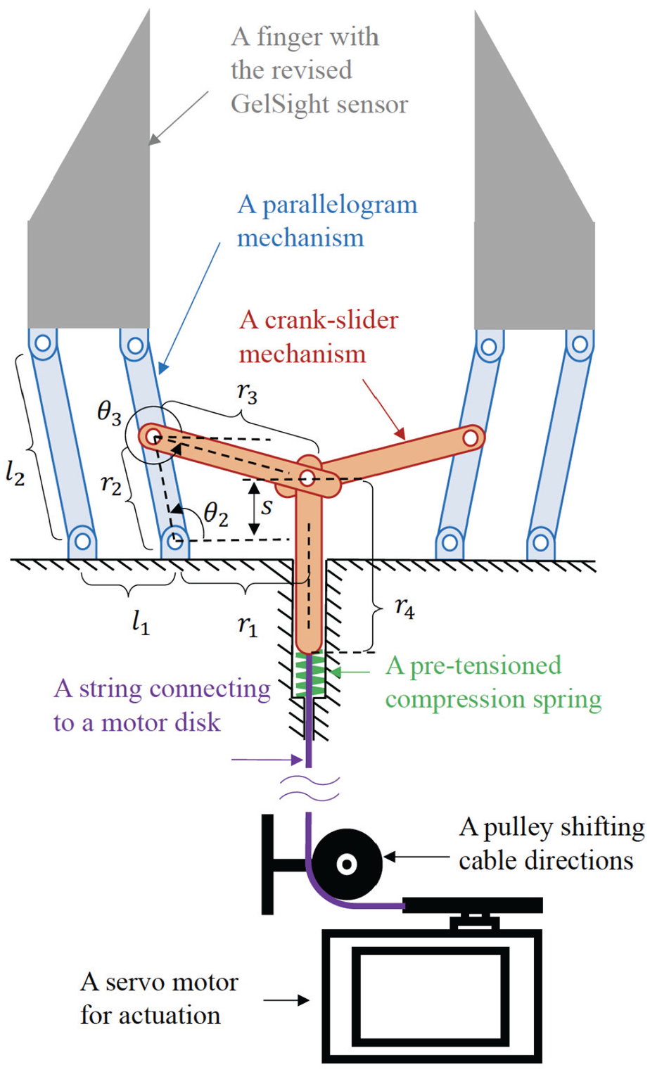
Mechanism design. A servo motor drives the slider-crank mechanism via the slider–string–spring system, actuating the parallelogram mechanism via the crank linkage, and finally yielding the motion of opening/closing of the gripper.
4.1.1. Mechanism design
Parallelogram mechanisms are widely used to yield lateral displacement and slider-crank mechanisms are broadly employed to actuate the parallelogram mechanism for parallel grippers. We use them to facilitate parallel grasping. To make a compact actuation mechanism, we use a tendon-driven system.
One end of a string (tendon) is tied to a motor disk which is fixed on the servo motor installed in a motor case. The other end of the string is tied to the slider as shown in Figure 3. We use a compression spring between the slider and the motor box with pre-tension forming a slider–string–spring system. The string then passes through a pulley to change its direction. One end of the crank linkage is connected to the slider and the other is coupled with the rocker of the parallelogram mechanism. The finger is attached to the coupler of the parallelogram mechanism. The string drives the slider down, actuating the parallelogram mechanism via the crank linkage and producing the desired lateral displacement of the finger. Two fingers assembled symmetrically around the slider yields a parallel gripper.
4.1.2. Mechanism dimensions
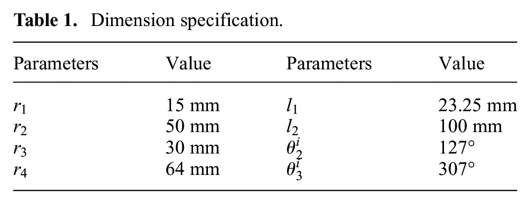
The next step is to determine the dimensions of the gripper. The design guidelines are as follows: (1) the maximum opening of the gripper is targeted at 100 mm, i.e., 50 mm displacement for each finger; (2) the parallelogram mechanism should fit the size of the revised GelSight fingertips; (3) reduce overall size and weight of the gripper as much as possible. According to the kinematics of the parallelogram and slider-crank mechanism as well as the aforementioned constraints, we designed a gripper with the dimensions in Table 1. Refer to Figure 3 for the definition of all variables. Note that
Dimension specification.
4.1.3. Compliant joint design
The original gripper design is composed of four sets of rigid parallelogram mechanisms (two sets on each side), which contains 28 assembly pieces and consumes assembly time. Compliant mechanisms (Howell, 2001) can produce exactly the same motion as those produced by rigid body mechanisms, but greatly reduce the part count and assembly procedures. We consider to use compliant joints to simplify the parallelogram mechanism.
Modeling and analysis of compliant mechanisms is however more complex than that of rigid-body mechanisms due to their infinite degrees of freedom (DOFs) and complex deformations. Screw theory-based methods (Hopkins and Culpepper, 2010a,b; Morrison and Su, 2020), beam theory (Awtar et al., 2007; Tolou and Herder, 2009), topological synthesis (Frecker et al., 1997), and pseudo-rigid-body (PRB) model (Howell and Midha, 1994, 1995) are the common methods to model and analyze the compliant mechanisms. Among those approaches, the PRB model bridges the compliant mechanisms and rigid body theories, which will be used in this work.
The PRB model provides a simple and computationally efficient solution to analyze kinematics and statics (kinetostatic) of the compliant mechanisms. Given a specific compliant mechanism, the kinetostatic analysis of the mechanism with the PRB model is referred to the forward analysis. If we know a particular rigid-body mechanism, the design of a corresponding compliant mechanism is referred to the inverse analysis. In this work, we consider to leverage the latter one to design a corresponding compliant mechanism to replace the rigid parallelogram mechanisms.
The rigid parallelogram mechanism and the corresponding gripper are as shown in Figure 4(a). Considering the revolute joint as the pseudo-rigid joint, one can replace it by the living hinge with the inverse analysis. The living hinge is a special form of a flexural pivot with little resistance throughout its deflection (Howell et al., 2013). With the substituted living hinges, one can convert the mechanisms in Figure 4(a) into the compliant parallel-guiding mechanism and the corresponding gripper in Figure 4(b).
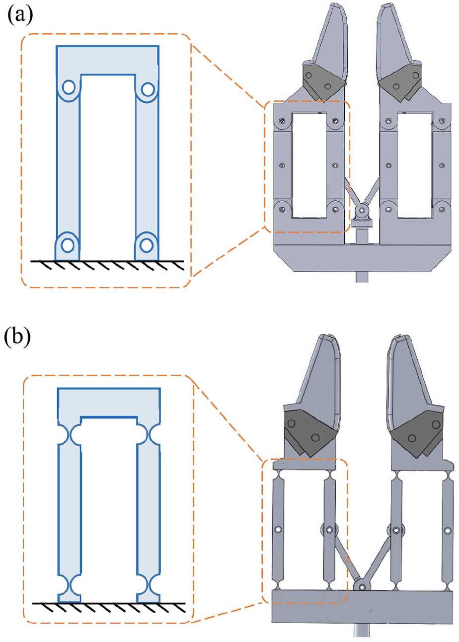
Compliant joint design. (a) The rigid parallelogram mechanism includes 28 assembly parts. (b) The compliant parallel-guiding mechanism replaces the rigid parallelogram mechanism reducing the assembly parts from 28 pieces to a single piece.
We use the living hinge design to convert the rigid parallelogram mechanism in Figure 4(a) to an equivalent compliant parallel-guiding mechanism to reduce the assembly process. The living hinge design reduces the 28 pieces of the rigid mechanism to a single part while offers the approximately same kinematics functionality. The overall size of the final prototype has length
4.1.4. Actuation
We select a high-torque and high-speed servo motor, dynamixel XM430-W210-T from Robotis, as the actuator for the gripper. It offers 77 rpm no-load speed and 3 N.m stall torque. According to the kinematics analysis of the crank-slide mechanism, we map the motor speed (
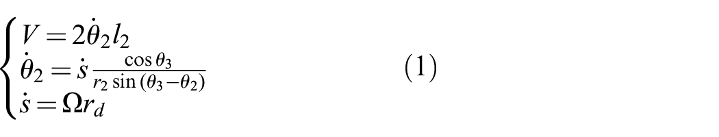
where
where
4.2. Perception
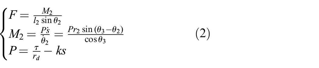
Figure 5 illustrates the process to extract cable pose, cable force, and grasp quality from tactile images.
Tactile perception. (a) Gripper with GelSight sensors grasping a cable. (b) Top view of the gripper grasping different cable configurations and the corresponding cable pose estimations. The white ellipse shows the estimation of the contact region. The red and green lines show the first and second principal axes of the contact region, with lengths scaled by their eigenvalues. (c) Top view of pulled cable while the gripper registers marker displacements indicating the magnitude and direction of the frictional forces.
4.2.1. Cable pose estimation
First, we compute depth images from the raw tactile images by estimating surface normal and applying a fast Poisson solver (FPS) for integration (Yuan et al., 2017). Then, we extract the contact region by thresholding the depth image. Finally, we use principal component analysis (PCA) on the contact region to get the principal axis of the imprint of the cable on the sensor.
4.2.2. Cable friction force estimation
We use blob detection to locate the center of the black markers in the tactile images (Dong et al., 2018). Then we use a matching algorithm to associate marker positions between frames, with a regularization term to maintain the smoothness of the marker displacement flow. We compute the mean of the marker displacement field (
4.2.3. Cable grasp quality
In this task, we evaluate the grasp quality (
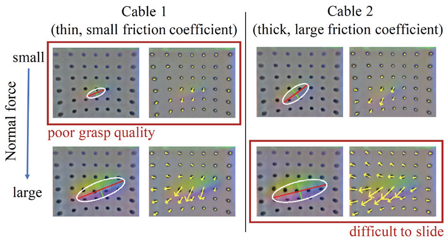
Trade-off between tactile quality and sliding friction. Larger gripping forces lead to higher-quality tactile imprints but difficult sliding. With the same normal force, the grasp quality and friction force varies among cables. The tactile-reactive control adjusts to different cables.
4.3. Control
4.3.1. Cable grip controller
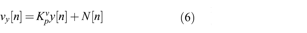
The goal of the grip controller is to modulate the grasping force such that (1) the friction force stays within a reasonable value for cable sliding (too small and the cable falls from the grip, too large and the cable gets stuck), and (2) the tactile signal quality is maintained. We employ a combination of a PD controller and a leaky integrator. The PD controller uses the mean value of the marker displacement (
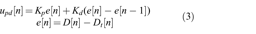
where
where
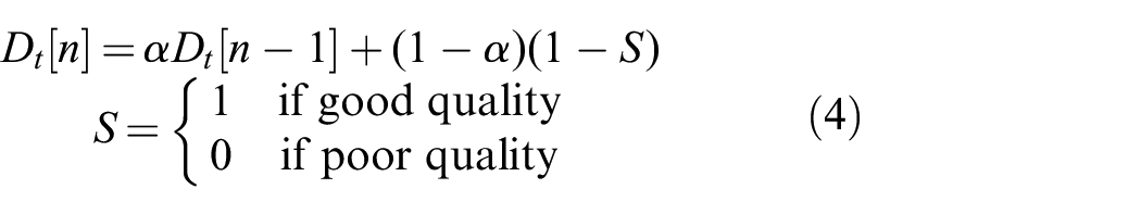
4.3.2 Cable-gripper dynamics model
We model the cable-gripper dynamics as a planar pulling problem. As shown in Figure 7, the region of the cable in contact with the tactile sensor (blue rectangle on the right) is represented as a 2D rigid sliding object. We parameterize its position and orientation with respect to
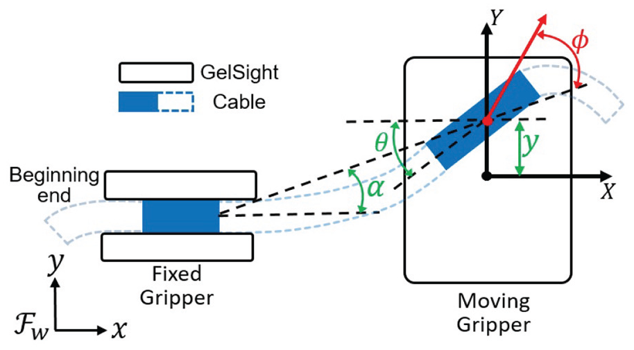
Model cable-gripper dynamics. Schematic diagram of the planar cable-pulling modeling.
As a deformable gel surface has complex friction dynamics, we use a data-driven method to fit a linear dynamic model rather than first principles. The state of the model is

where
To efficiently collect data, we use a simple proportional (P) pulling controller as the base controller supplemented with uniform noise for the data collection process. The P controller controls the velocity of the robot TCP in the
where
4.3.3. Cable pose controller
The goal of the cable pose controller is to maintain the cable position in the center of the tactile sensor (
We formulate an LQR controller with the
4.4. Robotic cable manipulation flowchart
An overview of the robotic cable manipulation flowchart is given in Figure 8, which includes the major components of the system: tactile perception, pose controller, and grip controller. The flowchart presents an overview of the perception and control algorithms. The perception module takes the raw feedback (raw image) from the tactile sensors as the input, and generates the cable pose, marker displacement, and contact area as the outputs. On one hand, the cable pose is fed to the pose controller, generating action commands applied to the robot to modulate the pose of the cable in the gripper. On the other hand, the marker displacement and contact area are fed to the grip controller, generating action commands applied to the gripper to modulate the griping force. Note that the flowchart reflects the logic of the cable-following task, and the insertion task is not included in the flowchart for the sake of brevity.
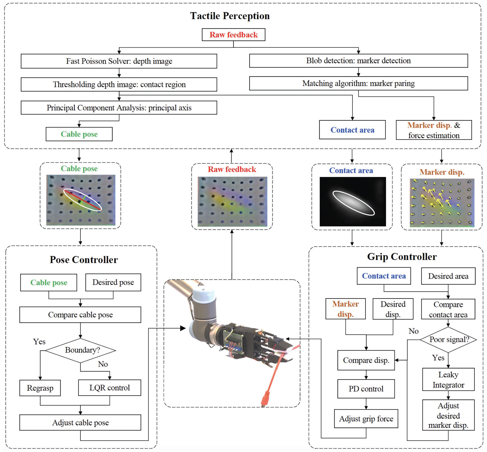
The robotic cable manipulation flowchart. The flowchart includes three modulus: tactile perception, pose controller, and grip controller.
5. Experiment
5.1. Experimental setup
The experimental setup in Figure 9 includes a 6-DOF UR5 robot arm, two reactive parallel-jaw grippers (as described in Section 4.1) and two pairs of revised fingertip GelSight sensors attached to the gripper fingers. One of the grippers is fixed on the table and another one is attached to the robot. The control loop frequencies of the UR5 and the gripper are 125 and 60 Hz, respectively.
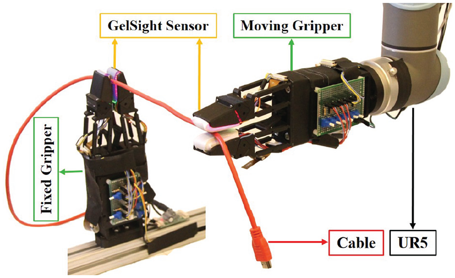
Experimental setup. UR5 robot arm and two reactive grippers with GelSight sensors.
We use five different cables/ropes to test the controllers (Figure 14, bottom): thin USB cable with nylon surface; thick HDMI cable with rubber surface; thick nylon rope; thin nylon rope; and thin USB cable with rubber surface.
5.2. Cable-following experiments
5.2.1. Experimental process
The beginning end of the cable is initially grasped firmly with the fixed gripper secured at a known position. The moving gripper picks up the cable and follows it along its length until reaching its tail end. During that process, the grasping force is modulated with the cable grip controller and the pose of the cable is regulated with the cable pose controller. We convert the control input
where
5.2.2. Metrics
We use three metrics to evaluate performance:
ratio of cable followed versus total cable length;
distance traveled per regrasp, normalized by the maximum workspace of the moving gripper;
velocity of the sliding task, normalized by maximum velocity in the
Note that all these metrics have a maximum and ideal value of 1.
5.2.3. Controller comparison
We compare the proposed LQR controller with three baselines: (1) purely moving the robot to the
5.2.4. Generalization
We conduct control experiments with the LQR robot controller + PD gripper controller to test the performance across (1) different velocities (
5.3. Cable-following and insertion experiment
An illustrative application of the cable-following skill is to find a connector at the end of a cable to insert it. This is a robust strategy to find the connector end of a cable when it is not directly accessible or under position uncertainties. Here we conduct an experiment on a headphone cable. The relative position in the workspace of the hole where to insert the connector is calibrated. The cable-following process is identical to what we illustrated in the previous section. We detect the plug (thick) based on its geometry difference compared with the cable (thin) using the GelSight sensor. To estimate the pose of the plug before insertion, we use the same tactile estimation method as used to estimate the cable pose during cable following.
6. Experimental results
In this section, we evaluate the performance of the linear dynamic model. We then detail the results of the cable-following experiments with different robot controllers, different velocities and different cables, according to the evaluation metrics. See Figure 14 for a summary. We also show the results of the cable-following and insertion experiment (Figure 13).
6.1. Linear dynamic model evaluation
We evaluate the learned linear dynamic model with a collected dataset of cable-gripper interactions.
6.1.1. Data collection
We collect the data in a similar way as the system runs at the test time, as described in Section 5.2, experimental process. However, we let the fixed gripper always grip the beginning end of the cable, so that the data collection can run repeatedly. The sliding motion can reset the cable to different initial configurations. In addition, we add some perturbances to the initial cable configurations for data diversity. We use approximately 3,000 data points with a single cable. Each data point contains the measured states
6.1.2. Evaluation
Figure 11 shows the performance of the linear regression model over
6.2. Controller evaluation
We further evaluate the LQR controller with the learned linear dynamic model, and demonstrate it is sufficient to accomplish the task efficiently.
We compare four different robot controllers: open-loop, open-loop with emergency regrasps, P controller, and LQR controller. The top row in Figure 14 shows that the open-loop controller only follows in average 36% of the total length of the cable. The gripper loses the cable easily when it curves. The simple addition of emergency regrasps is sufficient for the open loop controller to finish the task. This indicates that a timely detection of when the cable is about to fall from the gripper is important for this task. This controller, however, still requires many regrasps and is slower than the P and the LQR controllers. The results show that the LQR controller uses the fewest regrasps compared with other controllers. The LQR controller does not show much experimental improvement in the velocity metric, possibly because the robot travels more trying to correct for cable deviations.
Figure 10 shows snapshots of the experimental process using the LQR controller. Note that this controller always tries to move the gripper back to the center of the trajectory once the cable is within the nominal configuration since
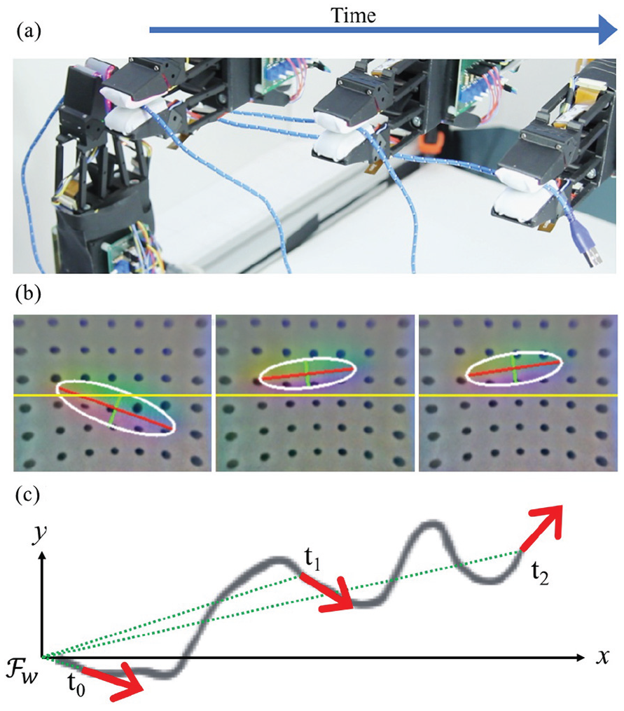
Cable-following experiment. For three instances in time: (a) camera view; (b) pose estimation from tactile imprints, where the yellow line in the center indicates the desired in-hand pose alignment; (c) top view of the trajectory of the end-effector and velocity output of the LQR controller, shown in red. The green dotted line illustrates
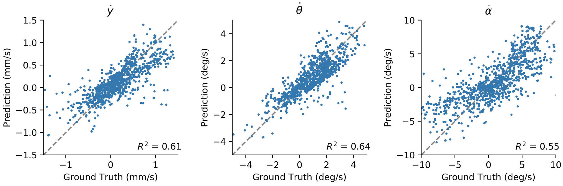
Predicted versus actual velocity
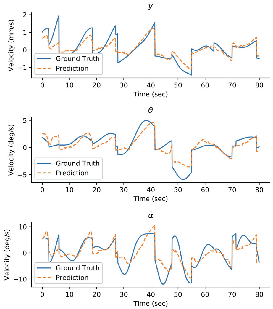
Sequence of predicted (orange dashed line) and actual (blue solid line) velocity
6.3. Generalization to different velocities
The model of the cable-gripper dynamics is fit with data collected with robot velocity of 0.025 m/s. We also test the LQR controller at 0.045 and 0.065 m/s. The results in the second row of Figure 14 show that the performance does not degrade, except requiring more regrasps per unit of distance traveled. This is likely because, going faster, the controller has less time to react to sudden pose changes and, therefore, tends to trigger regrasps more. Although the number of regrasps increases with larger velocity, the total time is still shorter due to the faster velocity.
6.4. Generalization to different cables
We also test the system with the LQR controller on five different cables, each with different physical properties (diameters, materials, stiffness). In experiments, the system generalizes well and can follow 98.2% of the total length of the cables.
Comparing the performance on the different cables shows that cable 4 (thin and light nylon rope) requires the most regrasps. It is difficult to adjust in-hand pose since it is very light and the unfollowed part of the cable tends to move with the gripper. The cable with best performance is cable 5 (thin and stiff rubber USB cable), which is stiff and locally straight most of the time.
The tactile reactive gripper in this paper is designed to manipulate cables in our daily life such as USB cables, earbud cables, and ethernet cables. A common feature of these cables is that they are relatively thin. For cables with larger diameter, the contact region will increase, and the depth (cable penetration into gel) will decrease, given the same gripping force. Accordingly, the major axis of the ellipsoid and the minor axis of the ellipsoid will increasingly become of similar magnitude, which will be difficult to estimate the direction of the cable. One potential solution is to scale up the sensor and the gripper for larger diameter cables or, as humans do, use larger contact areas, such as multiple fingers, or palms.
6.5. Cable following and insertion
The process to grasp, follow, and insert the headphone cable is illustrated in Figure 13. Parts (a) and (b) show the robot following the cable all the way to the plug and identifying the moment it reaches the plug. After the plug is detected, the fixed gripper opens and the robot moves the plug over the headphone jack on the phone shown in Figure 13(c).
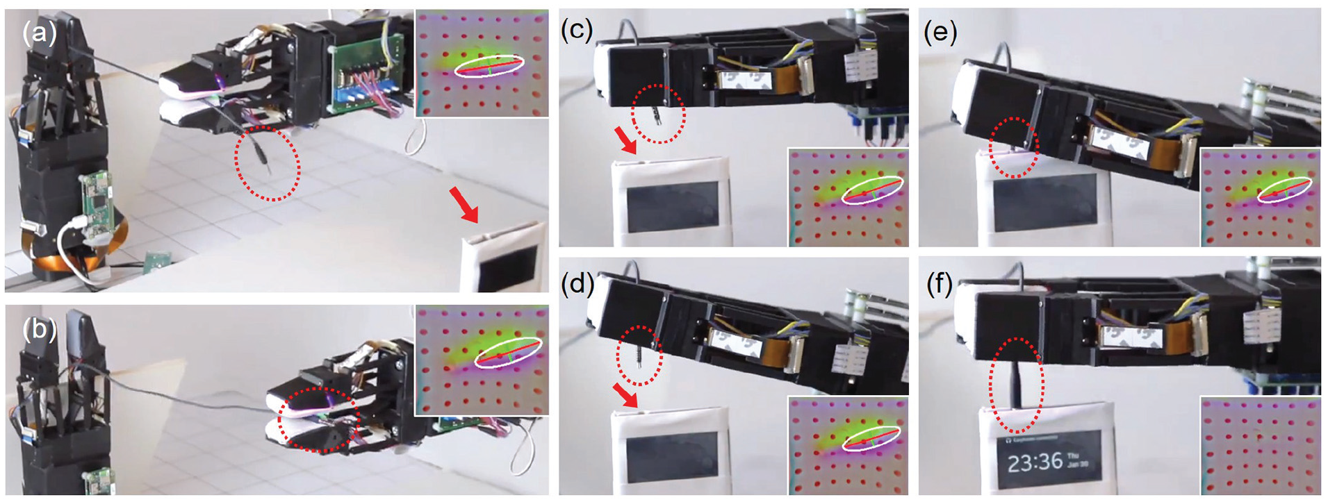
Headphone cable-following and insertion process. (a), (b) Cable following to the plug end, (c) plug on top of the hole with pose mismatch, (d) plug pose adjusted and aligning with the hole, and (e), (f) cable plugged into the headphone jack on the phone. The plug is labeled with red circle and the headphone jack is labeled with a red arrow.
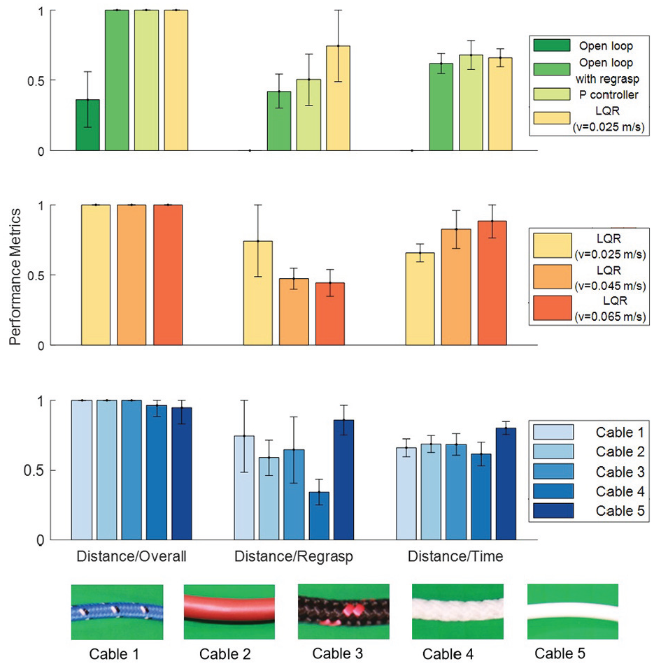
Experimental results. Different robot controllers (top), different following velocities (middle), different cables (bottom). For visualization, the three metrics are normalized to
After cable sliding, the gripper uses the tactile feedback from a GelSight sensor to localize the plug and align it with the hole, as shown in Figure 13(d). Afterwards, the robot moves down to insert the cable into the headphone jack in Figure 13(e) and (f). We repeat the insertion only experiment (plug directly fed to the gripper by human with random pose) for 20 times and can insert the headphone plug with an 85% success rate. For better visualization of combined experiments of cable following and insertion, see the videos at http://gelsight.csail.mit.edu/cable/
6.6. Failure cases
We observed several failure cases that deserve further thought.
7. Conclusions and discussion
7.1. Conclusions
In this paper, we have presented a perception and control framework to tackle the cable-following task. We show that the tight integration of tactile feedback, gripping control, and robot motion, jointly with a sensible decomposition of the control requirements is key to turning the a priori complex task of manipulating a highly deformable object with uncontrolled variations in friction and shape, into an achievable task. The main contributions of the work are as follows.
The successful implementation of the tactile perception and model-based controller in the cable-following task, and its generalization to different cables and to different following velocities, demonstrates that it is possible to use simple models and controllers to manipulate deformable objects. The illustrative demonstration of picking and finding the end of a headphone cable for insertion provides a example of how the proposed framework can play a role in practical cable-related manipulation tasks.
7.2. Discussions
Robotic manipulation has had an effect on a range of real-world tasks, such as pick and place and assembly. In most cases, the objects manipulated are rigid. Manipulation of deformable objects is more challenging because soft materials are represented by more complex states and follow more complex dynamics. A common approach to manipulating deformable objects is to iteratively transition between static stable states via pick-and-release sequences. This reduces complexity, but also makes manipulation inefficient. Natural manipulation of deformable objects observed from humans involves dynamic interactions such as sliding along an earbud cable to find the plug or sliding along the edge of a sheet to find its corner.
This “sliding” motion yields new challenges: cables are highly deformable with complex dynamics, and the operation requires real-time adjustments. Correspondingly, the design of control policies for this type of task becomes difficult. However, we can exploit the local constraints imposed by the same sliding motion to simplify control, specially when supported by state feedback via advanced tactile sensors.
7.2.1. Global versus Local dynamics
From a global perspective, the state and dynamics of a deformable object are computationally challenging due to their large number of DOFs. Figure 15(left) shows the global view of an earphone cable and a piece of cloth. However, the state and dynamics are simplified for specific types of interaction. For example, when the cable or piece of cloth are in tension, it is easier to control the task of sliding the fingers. The dimension of the deformable object is reduced by the same constraints imposed by the sliding motion. This makes it possible to design simple and efficient controllers for real-time robotic manipulation. In Figure 15(right) the state of cable and the cloth is simplified in between the two grasping points.
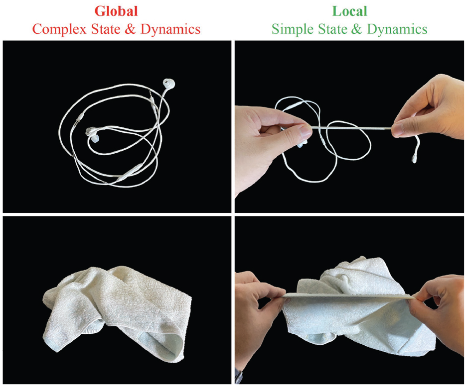
Simplified state and dynamics from sliding. The comparison of the global (left) and local (right) perspective of manipulating a piece of cable and fabric. From a global view, it is challenging to model the state and dynamics of a deformable objects due to the large number of DOFs. However, the sliding motion adds constraints to the objects, simplifying the local state and dynamics. It enables fast and reactive manipulation skills.
It is worth noting that it would be challenging to apply the current pose estimation method (PCA) to soft cloths because the contact region may no longer be an ellipsoid. One may consider using a different method, maybe a supervised data-driven method, to estimate the principal direction of the edge of the cloth. The same idea applies to very soft cables such as wool. In terms of the pose controller, soft cloths would also be more challenging than relatively stiff cables for robotic manipulation. We expect that leveraging extrinsic dexterity like the gravity of fabric for self-straightening or partial table support with external forces, will be important. The grip controller might also need to be adjusted such that the gripper opens further to better adjust the in-hand pose when required. However, in general, the idea of following tactile features (such as principal axis/edges) of deformable objects can serve as an alternative motion primitive to alleviate the complexity of state and dynamic modeling.
The cable-following technique we demonstrate in this work bypasses the complexities of global state estimation and control by designing policies that rely only on local state feedback, which can be captured by tactile sensors. The technique to change the grasp on the cable by sliding the fingers can be thought of as a closed-loop primitive action (the “sliding regrasp”) applicable to a range of objects (not just cables, but also rigid objects and other types of deformable objects, e.g., cloth). On the perception side, this requires a sensor that can track local motions of the local geometry at contact. On the control side, this requires a model of the local pulling–sliding dynamics.
7.2.2. Contact state control and object state control
This work proposes a novel control framework for robotics manipulation of deformable objects with sliding operations by decoupling the complex manipulation policy into two simple independent controllers: contact state control (i.e., cable grip controller) and object state control (i.e., cable pose control). This is equivalent to the decoupling control approach proposed for tactile dexterity by Hogan et al. (2020) with manipulation primitives for rigid objects, and by enforcing sticking. In the case of this work, however, we apply it to a primitive aimed at manipulating deformable objects with sliding interactions. The key idea is the same: one controller (contact state controller) regulates the interaction between the gripper and object to a nominal contact state, and a second controller (object state controller) manipulates the object by exploiting the regulated nominal contact state.
In our case, the contact state controller regulates the contact forces between the gripper and cable to facilitate smooth sliding, while the object state controller maintains the cable at the center of the gripper. These two orthogonal controllers interact and benefit from each other. By decoupling the control policies into two orthogonal controllers, we can use simple controllers (PID and LQR, respectively) in separate threads to perform the task, enabling real-time control for complex dynamic manipulation of deformable objects.
Footnotes
Acknowledgements
This paper extends the paper that appeared in the proceedings of the 2020 Robotics: Science and Systems (She et al., 2019).
Funding
This work was supported by the Amazon Research Awards (ARA), the Toyota Research Institute (TRI), and the Office of Naval Research (ONR; grant number N00014-18-1-2815). Neha Sunil is supported by the National Science Foundation Graduate Research Fellowship (grant number NSF-1122374). This article solely reflects the opinions and conclusions of its authors and not Amazon, Toyota, ONR, or NSF.