
Abstract
In this work we consider the current certification process of applications with physical human–robot interaction (pHRI). Two major hazards are collisions and clamping scenarios. The implementation of safety measures in pHRI applications typically depends strongly on coordinates, e.g., to monitor the robot velocity or to predict external forces. We show that the current certification process does not, in general, guarantee a safe robot behavior. In particular, in unstructured environments it is not possible to predict all risks in advance. We therefore propose to control the energy of the robot, which is a coordinate invariant entity. For an impedance controlled robot, the total energy consists of potential energy and kinetic energy. The energy flow from task description to physical interaction follows a strict causality. We assign a safe energy budget for the robot. With this energy budget, the presented controller auto-tunes its parameters to limit the exchanged kinetic energy during a collision and the potential energy during clamping scenarios. In contact, the robot behaves compliantly and therefore eliminates clamping danger. After contact, the robot automatically continues to follow the desired trajectory. With this approach the number of safety-related parameters to be determined can be reduced to one energy value, which has the potential to significantly speed up the commissioning of pHRI applications. The proposed technique is validated by experiments.
1. Introduction
Despite the prognosis of market researchers, collaborative robots are still a minority in the industrial sector. While 400,000 industrial robots were installed in 2018 (International Federation of Robotics, 2019a), only 12,000 professional service robots were sold in the same year 1 (International Federation of Robotics, 2019b). One reason is the extensive and complicated certification process required to integrate a collaborative robot in a manual work process. The process usually begins with a virtual set-up in simulation. First risk assessments have to be performed to identify possible hazards for the human when entering the robot workspace (International Organization for Standardization, 2010, 2011). The desired result of the risk assessment is to define how likely it is that the hazards harm the human and to provide measures to minimize these risks. Next, the real robot is installed and programmed with a range of velocities. After the robot process is implemented, the impact force of the robot in case of a collision is verified with a measurement device (Dombrowski et al., 2018). The international standard ISO/TS 15066 (International Organization for Standardization, 2016) defines bio-mechanical limits for each body region of the human. Thresholds are defined for two different contact scenarios: transient contact (i.e., collision) and quasi-static contact (i.e., clamping). A collision is a dynamic impact with the moving robot. A clamping scenario occurs when a robot continues to follow a pre-planned trajectory even though an obstacle has been encountered. In the risk assessment, the programmer of the robot application has to decide which contact scenario is likely to occur. Moreover, for each part of the robot application the affected body regions have to be identified. In an iterative manner, the robot velocity is reduced until no bio-mechanical threshold is violated (Figure 1).
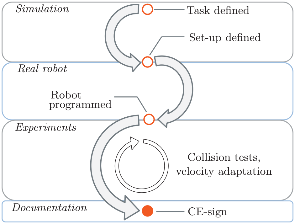
Simplified certification process of a collaborative robot cell. The robot movement is roughly planned in simulation. To satisfy the force thresholds in ISO/TS 15066, possible contact scenarios are identified and respective body regions are selected. The robot process is programmed with a range of velocities. Collision measurements are performed in order to evaluate the robot impact. Iteratively, the velocity of the robot is adapted. To prove compliance with existing standards and regulations, extensive documentation is needed.
Typical robot controllers are divided into two successive stages: motion planning and motion execution. During motion planning, a reference trajectory is computed for every robot joint. The result is then passed to the motion execution stage, during which the planned joint trajectories are tracked as accurately as possible (Siciliano et al., 2009). For physical human–robot interaction (pHRI), these controllers rely on the prediction of robot collisions with the environment (Bergner et al., 2019; Lee and Song, 2015; Phan et al., 2011). As the reference trajectory cannot be modified during motion, the robot executes a stop reaction if a safety-related signal exceeds a pre-defined threshold (e.g., the distance between robot and environment is too small or the collision force with the environment is too large). In ISO 10218-1 (International Organization for Standardization, 2011) robot motion is defined as the main risk source for the human. Therefore, only stop reactions are considered to be safe. For constricted workspaces, where the robot and human work closely together, this can easily lead to clamping dangers. Moreover, for scenarios where the robot brakes are activated during a quasi-static contact, the human has no means to escape from a clamping scenario (De Luca et al., 2006).
Reactive control schemes merge the planning and execution phases. Therefore, it is possible to develop unified strategies for collision detection and reaction (Haddadin et al., 2008a). Several approaches for collision detection have been proposed (Birjandi et al., 2020; Fritzsche et al., 2011; Haddadin et al., 2017; Liang et al., 2020). If the human and robot share the same workspace, the collision point on the robot structure is not known in advance. Therefore, it is important that the detection does not depend on the impact location, nor on the current robot configuration. Different safety-related reaction strategies exist. One approach is to apply monitoring functions during the robot movement and automatically adapt the controller parameters during run-time (Haddadin et al., 2008b; Muñoz Osorio et al., 2019; Navarro et al., 2016; Raiola et al., 2018). The goal of those controllers is to limit the potential robot impact in case of an unintended collision. Other work focuses on active robot reactions that are executed after a collision has been detected (De Luca and Flacco, 2012; Khan et al., 2014; Laffranchi et al., 2009). For unstructured environments, it is important to ensure that these active reactions do not lead to new risks. Moreover, no controlled robot reaction is fast enough to have a significant influence on the first collision impact (Haddadin et al., 2008b,c).
A promising field of research is learning-based approaches to support pHRI, e.g., imitation learning (Calinon et al., 2010; Rozo et al., 2013) and dynamic motion primitives (Ijspeert et al., 2013; Schaal, 2006). The goal of these approaches is to “demonstrate” to the robot human-like interaction and therefore resolve unsafe behavior.
Learning-based approaches often depend on appropriate sensors to monitor the environment. Even though considerable research in safety-related perception and vision has been done in recent years (Beetz et al., 2015; Charalampous et al., 2017; Chen and Song, 2018; Flacco and De Luca, 2017; Flacco et al., 2015; Sadrfaridpour and Wang, 2018), there is a significant lack of certified sensors, e.g., to calculate “safe distances,” to predict human intentions and to supervise sharp objects at the robot end-effector. If such sensor functions should be used for pHRI, they have to fulfill the strict requirements of ISO 10218-1 and ISO 13849-1. This means that for a severe and frequently appearing risk, the safety-related software has to be designed in a redundant manner (i.e., “Category 3”) and the probability that failures of the safety system remain undetected has to be less than
To program collaborative applications coordinate frames are typically placed on the robot structure, e.g., to monitor Cartesian velocities or predict external forces. As may be anticipated, unmonitored body parts on which no coordinate frame has been placed can easily cause risks for the human. Imagine a service robot working in a supermarket surrounded by children. To be productive, it is desired that such a robot moves at high velocity. However, the maximum velocity of the robot has many constraints. Some of the constraints are robot-related (e.g., movement direction and curvature) and others are due to the given environment (e.g., clamping dangers and number of surrounding people). Therefore, it is hard to define possible collision points and maximum limits for the robot velocity. For such applications, intrinsically safe controllers are needed that automatically adapt the robot behavior and exclude clamping danger.
Physical interaction can be characterized by energy exchange (Colgate and Hogan, 1988). A major advantage is that energy is a coordinate invariant entity. Energy shaping techniques in robotic control have been in use since 1981 (Takegaki and Arimoto, 1981). However, there is only limited work addressing the control of energy for safe pHRI. In most energy-related control approaches, the energy difference between two successive control cycles is compared in order to make a statement about the passivity of the robot. Passivity is an energy-based measure of stability (Ortega et al., 2001). Probably the most prominent passivity concept is the “energy tank” and “energy routing” approach originally proposed by Duindam and Stramigioli (2004), which can be used for telemanipulation (Ferraguti et al., 2015, 2013; Franken et al., 2011), to guarantee stability during contact (Schindlbeck and Haddadin, 2015; Shahriari et al., 2020, 2017) or to render nullspace projection approaches passive (Dietrich et al., 2016, 2017; Garofalo and Ott, 2018). Moreover, the energy tank concept has been proposed for safe pHRI (Raiola et al., 2018; Tadele et al., 2014). An energy tank constrains the robot energy to a finite amount. During movement, the robot extracts energy from the tank. In all approaches, the initial amount of energy in the tank is crucial. For pHRI this can lead to a conflict: on the one hand, the available energy should be high enough for the robot to fulfill its task; on the other hand, allowing a high energy value can pose a risk for the human in case of an unintended collision. Therefore, it might be worth exploring the allocation of an energy budget for each control cycle (Groothuis et al., 2018).
In this article, we address the coordinate dependency of the implementation of safety measures in pHRI applications. We review the current certification process with the help of an example application on a real robot. For the certification process, coordinate frames are used to monitor Cartesian velocities and predict external forces. We show that for a given robot task these strategies do not generally predict “unsafe” robot behavior. The novelty of this article is to assign a dynamic relationship to a contact scenario. This means that the contact is not only defined by the applied robot force but also influenced by the interacting environment. The coordinate invariant energy flow from the information (digital) domain to the energy (physical) domain determines the causality of the desired robot motion and the resulting impact force. We assign an energy budget to the robot to restrict the amount of energy flow in case of a collision. In our control approach, the robot is exposed to an artificial potential field. The controller auto-tunes this potential field at run-time to ensure that the energy budget is not violated. This is a powerful but simple approach, because small adaptations to existing controllers are sufficient. We can reduce the number of control parameters to be selected to one energy value. This approach is experimentally validated for its usability in pHRI. We use state-of-the-art certification devices to derive a safe energy budget for our example application. Thereby, collision and clamping risks are both taken into account.
2. Safe pHRI: classical approach
In order to certify a robot application, a risk assessment based on ISO 12100 has to be performed. The first step of the risk assessment is to list possible risks for the human. For pHRI, two major hazards are collisions and clamping scenarios, which will be treated in the remainder of the article.
2.1 Certification process of pHRI cells
In Figure 2, an exemplary robot application is shown which we use in the following to demonstrate the current certification process. Each robot application can roughly be divided into transfer motion, approach motion and process (Figure 2). During the transfer motion, collisions or clamping scenarios can occur. The approach motion mostly yields clamping dangers.
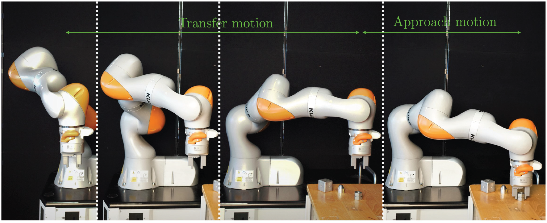
A typical robot application is divided into transfer motion and approach motion. At the end of the transfer motion, the robot is pre-positioned. Relative to this position, the workpiece is approached.
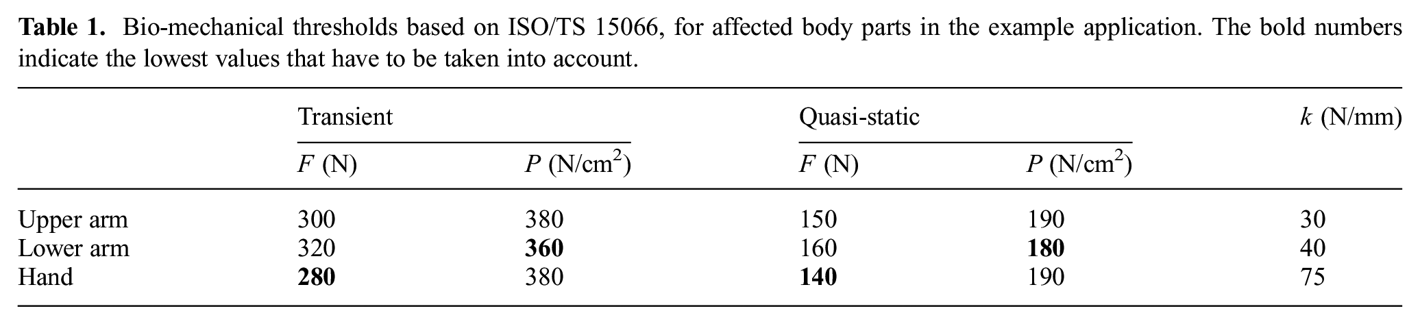
If a pHRI application is placed in a restricted and unstructured workspace, the contact scenario can not be determined in advance and the programmer of the robot cell has to assume the worst-case scenario. To determine the impact of a collision between the robot and the human, possibly affected body parts have to be identified. Therefore, ISO/TS 15066 provides bio-mechanical thresholds for different body parts of the human. Moreover, the stiffness
Bio-mechanical thresholds based on ISO/TS 15066, for affected body parts in the example application. The bold numbers indicate the lowest values that have to be taken into account.
In the next step of the risk assessment, possible collision points on the robot structure have to be determined in order to calculate the impact surface area during contact. The robot programmer analyzes the robot motion and selects the “sharpest” points on the robot structure, i.e., the surface with the smallest curvature. Often, the most exposed surface in the movement direction is selected. For our example application, we selected the white rounded cover around the cables of the robot flange as the most exposed surface that is likely to collide with the human arm during transfer motion (Figure 2). During the approach motion, it is possible that the human arm or hand becomes clamped between the table and the gripper jaws, which have a flat surface at the finger tips (Figure 2).
To analyze the severity of a collision and to guarantee conformity with ISO/TS 15066, each pHRI application is certified based on measurements. The desired output of the measurements are impact surface area and collision force. With this information, contact pressure can be calculated. We conducted such measurements for our example application. In Figure 3, the measurement setup for the transfer motion and the approach motion can be seen, with detailed technical specifications presented in Appendix B. Two test series were performed, one for the transfer motion and one for the approach motion.
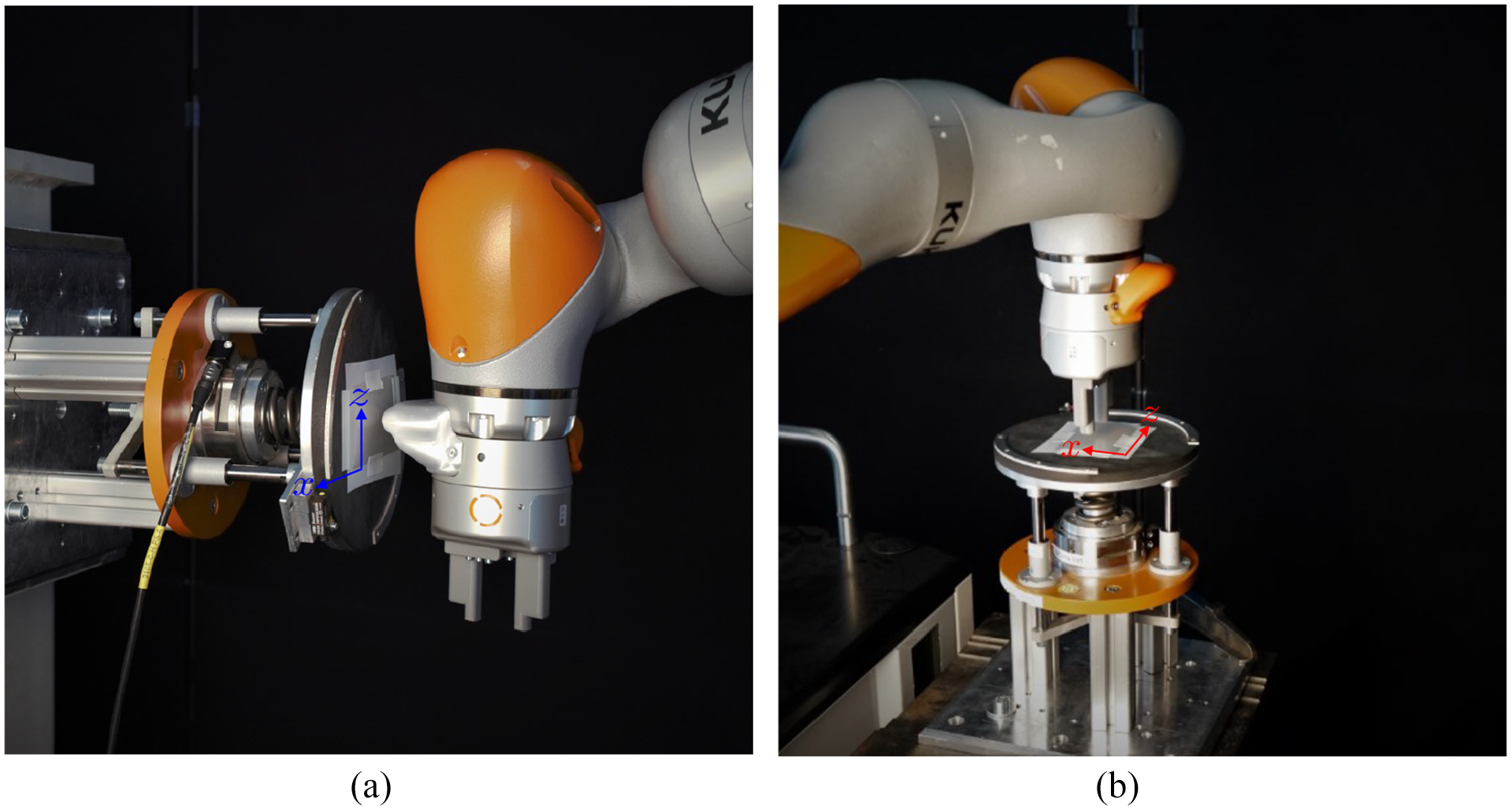
(a) Collision test with gripper cover during transfer motion. (b) Collision test with gripper jaws during approach motion. To determine the impact surface area and impact force during transfer motion (a) and approach motion (b), a collision measurement device was mounted on solid pillars. The robot application was started and the identified robot part collided with the measurement device. The tests were conducted with varying robot speeds to determine the maximum admissible bio-mechanical threshold.
The collision measurements were conducted with a measurement device that was mounted on a solid steel pillar. This simulated a quasi-static contact in which the human has no possibility to back up. The measurement device was equipped with a force sensor. On top of the force sensor, a spring was attached that simulated the stiffness of the human body part. The robot collided with a foam rubber pad that resembled the stiffness of the skin. In our experiments, the spring constants used were 25 N/mm (arm) and 75 N/mm (hand), for transfer motion and approach motion, respectively. These values emulated the stiffness values of the affected body parts, defined in Table 1. The foam rubber had a thickness of 0.01 m. To asses the impact surface area, a pressure sheet was fixed on the measurement device during the first test of each series (Figure 3). Using the software of the pressure sheet provider, the impact surface area was determined. This was done by outlining the area manually in the software (thin black line in Figure 4). For our experiments, the impact surface area for the transfer motion was
(a) Impact surface area for transfer motion:
As a last step of the risk assessment, safety measures have to be provided to keep the collision impact within an acceptable range. For contact scenarios, this means that the bio-mechanical thresholds of ISO/TS 15066 must not be exceeded. Collaborative robots provide measures to lower the impact during a contact scenario. For the KUKA LBR iiwa, integrated torque sensors can be used to detect a collision. Moreover, based on the torque sensors, external Cartesian forces can be predicted. In our experiments, a collision detection criterion of torque
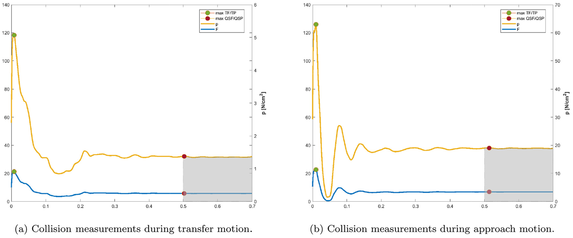
Every contact scenario has a transient and a quasi-static phase. During each phase, maximum force and pressure values are tracked. While for transient contact the maximum values are considered over the complete impact time, the maximum quasi-static values are assumed to be established 0.5 seconds after first contact (International Organization for Standardization, 2016). For our example application, we presumed an unstructured environment and considered a quasi-static contact scenario for the transfer and approach motions. Figure 5a shows the robot end-effector velocity in the direction of movement during the transfer motion. Approximately
(a) Velocity during a transfer motion. The velocity at the instant of collision is shown by a red star. For each trial, the velocity at the first impact instant was determined. (b) Force and pressure distribution for a collision during the transfer motion. While the maximal transient pressure and maximal QSP were far lower than the admissible threshold, the transient force was close to the permitted threshold of
Figure 6a shows the robot end-effector velocity in the movement direction of the approach motion. Unlike the transfer motion, high QSP values were observed since the gripper jaws had a small contact surface area (cf. Figures 4b and 6b). The robot velocity was iteratively adapted, until the QSP approximated the threshold for the lower arm (cf. Table 1 and Figure 6b). Note that
(a) Velocity at the collision instant during an approach motion. (b) Force and pressure during quasi-static contact. The robot velocity was iteratively adapted until the contact pressure value met the bio-mechanical threshold of
For this example application with a quasi-static contact scenario, for a collision with rounded robot parts (e.g., the gripper cover) transient force values were critical, whereas for parts with small impact surface areas (e.g., the gripper jaws) the QSP values were more important.
2.2 Specific aspects of the safety implementation
For the remainder of the article, consider a robot with
As shown in the previous section, the robot programmer has to determine critical points on the robot structure. For these points, coordinate frames are placed and the maximal velocity is evaluated. The calculation of the velocities is based on the Jacobian matrix

The first three rows of
To analyze a scalar value, the vector
(a) Velocity monitoring of a redundant robot. (b) Cartesian velocity magnitudes based on a Euclidean 2-norm. A redundant three-degree-of-freedom robot moving along the
To lower the impact of a collision, often joint torque sensors are used to detect a contact with the environment. External torques

Hereby, the Jacobian inverse
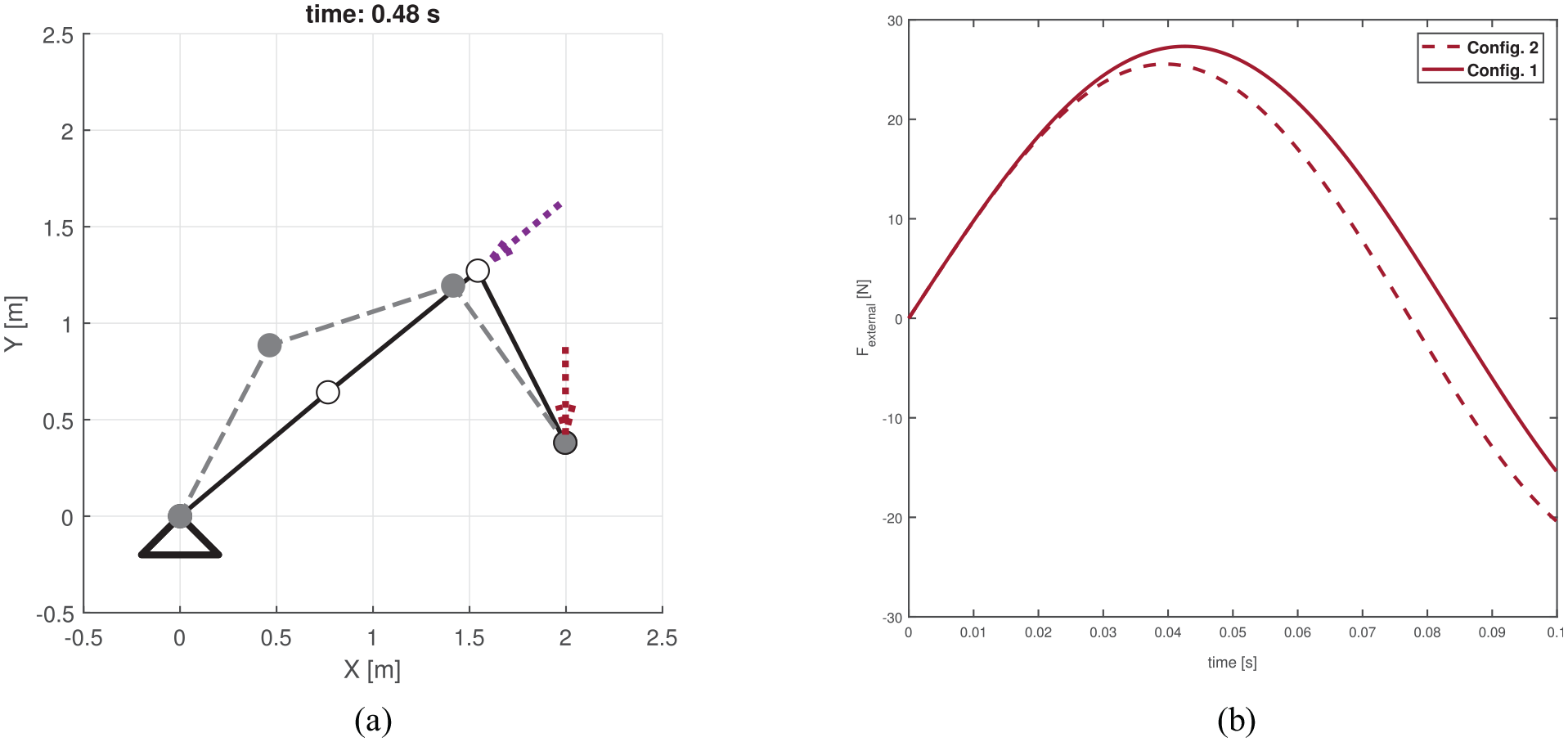
(a) External forces acting on robot. While the end-effector is moving upwards along the
The contact force is frequently described by a linear mass–spring–mass model (Haddadin et al., 2009; International Organization for Standardization, 2016; Rosenstrauch and Kruger, 2017). For a given direction, represented by the unit vector

The “end-point mobility tensor”
As can be seen in (3), the magnitude of
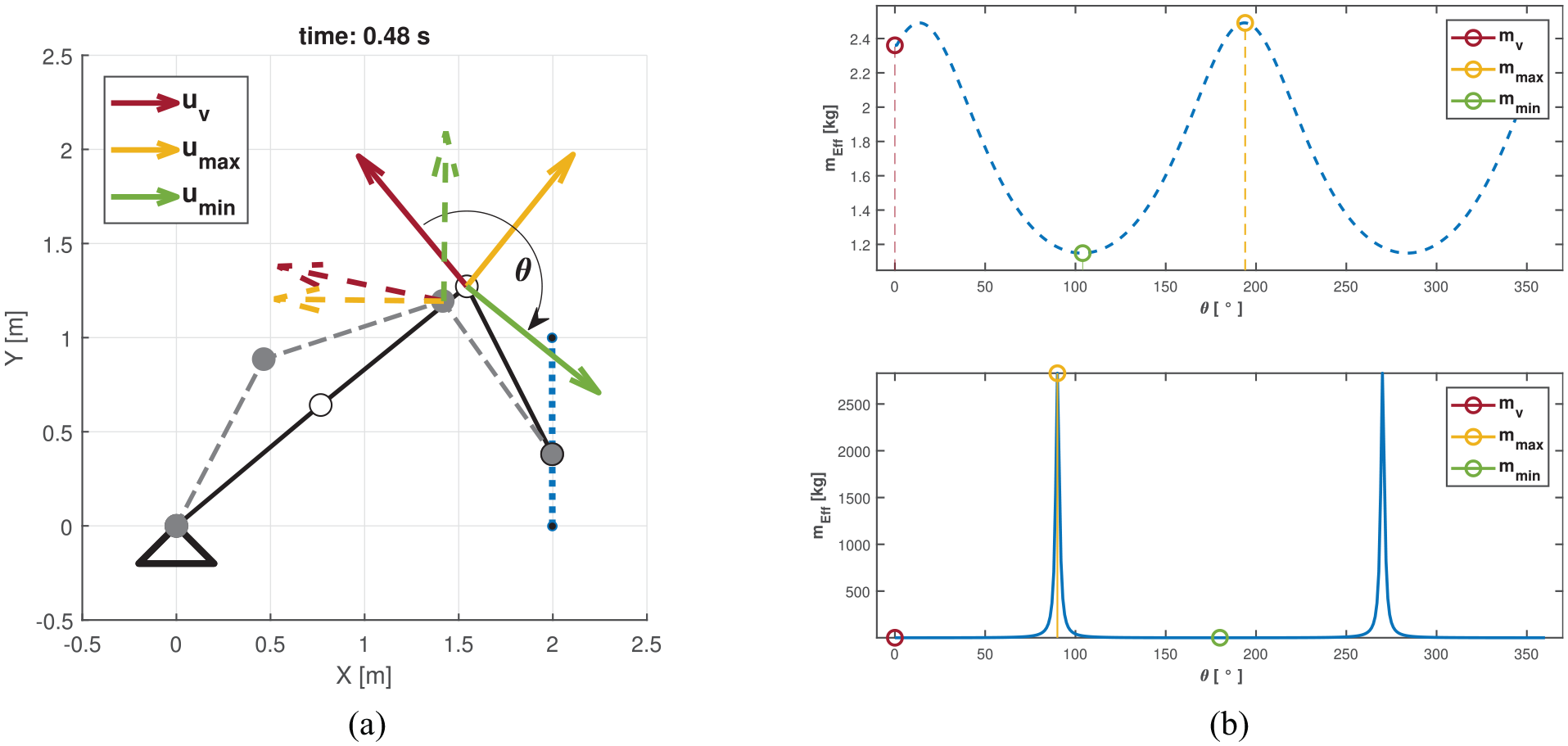
(a) Reflected inertia for two different feasible joint space trajectories with coordinate frames on joint 3. (b) The magnitude of
In our example application, we placed one coordinate frame on the end-effector to monitor and adapt its velocity. Additional high velocities, e.g., of the robot elbow, were not tracked and can represent an injury risk. Even if all appropriate coordinate frames have been placed, the clamping danger still exists. To comply with ISO 10218-1, the robot stops and the brakes are activated if an unintended contact is detected. This is especially disadvantageous for applications with restricted workspaces. This can be seen in our example application (Figures 5b and 6b): the remaining quasi-static force (QSF) values after the robot stopped were approximately 94.74 N and 65.06 N for the transfer motion and the approach motion, respectively. For the approach motion, a constant pressure of 180 N/cm2 remained. For our example application, the force and pressure values are in correspondence with ISO/TS 15066. However, a wrong choice of considered body parts (Table 1) will not eliminate all risks. Even if all affected body parts were identified correctly and all contact values were in correspondence with ISO/TS 15066, the programmer has to provide some means to release the human co-worker.
3. Coordinate invariant control of robot energy
A collision between a robot and its environment is a dynamic interaction and hence cannot be described with either velocities or forces alone (Folkertsma and Stramigioli, 2015; Stramigioli, 2015). Physical contact results in a robot response. It is important that this reaction should not evoke new dangers for the human (Haddadin et al., 2017). We control the energy of the robot, which is a coordinate invariant entity and therefore does not depend on the selection of coordinate frames. Our controller auto-tunes the total energy of the robotic system. The compliant robot behavior in quasi-static contact will protect the human from clamping scenarios.
3.1 Energy transfer during interaction
The interaction between the robot and its environment can be represented by an equivalent network (Hogan, 2014; Stramigioli, 2001) (Figure 10). For a given control input
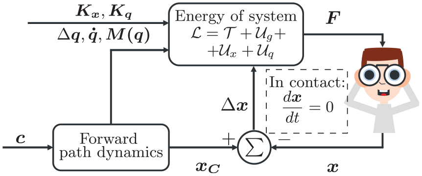
Norton equivalent network for contact dynamics between robot and human (inspired by Hogan (2014)). The robot is modeled as an impedance (left). A collision can be described at the interaction port
The total energy
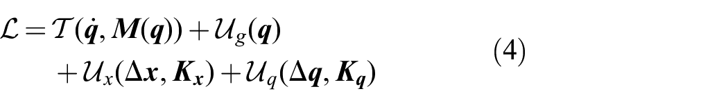
with
For an impedance controlled robot, the energy flow from the information domain (control command
We assign an energy budget to the robot system in order to ensure an intrinsically safe robot motion and safe contact behavior. Therefore, the force
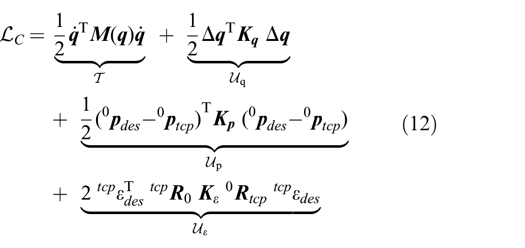
3.2 Control of potential energy
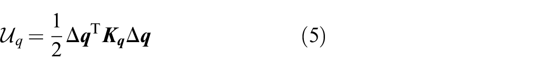
A robotic task can be described as an elastic potential (Stramigioli, 2001). For a desired joint space behavior, a simple linear choice for the potential function is
For Cartesian space, several methods exist to describe the impedance potential, e.g., Fasse and Broenink (1997), Caccavale et al. (1999), Stramigioli (2001), and Natale (2003). The main difference between the methods lies in the description of the rotational potential. One possibility is to describe the rotation with unit-length quaternions. The rotation matrix
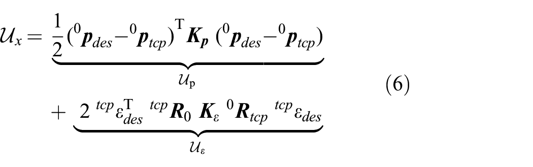
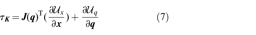
With (5) and (6), the task torque
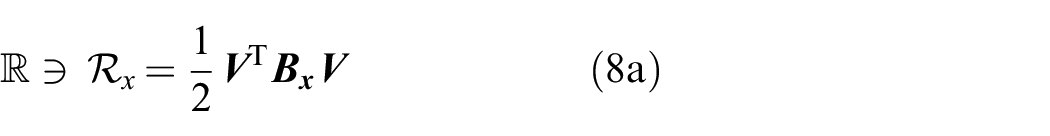
To guarantee an efficient robot behavior, we have to find an appropriate damping function. The dissipation function can be expressed with a Rayleigh function as
and
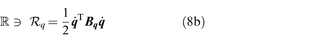
with corresponding resistive elements

where
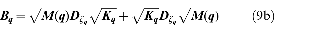
where

is the “kinetic energy matrix” defined in Khatib (1995).
The square roots of the matrices in (9a) and (9b) can be calculated by coordinate transformation, such that the symmetric positive-definite matrices
Using (8), the damping torque
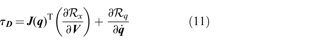
3.3 Energy budget for safe pHRI
If
We set an energy budget

If (13) is violated we can produce a new elastic potential
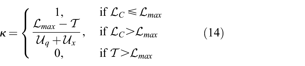
This approach will automatically bound the total energy of the robot. The condition for
Here,
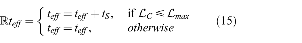
Second, we introduce an additional joint potential
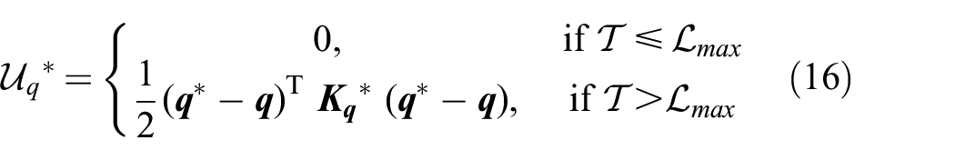
with
where
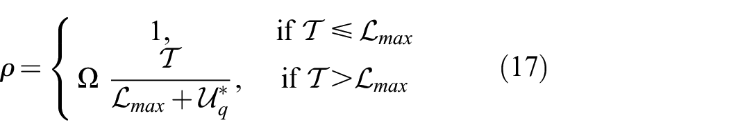
Finally, we can calculate the control torque
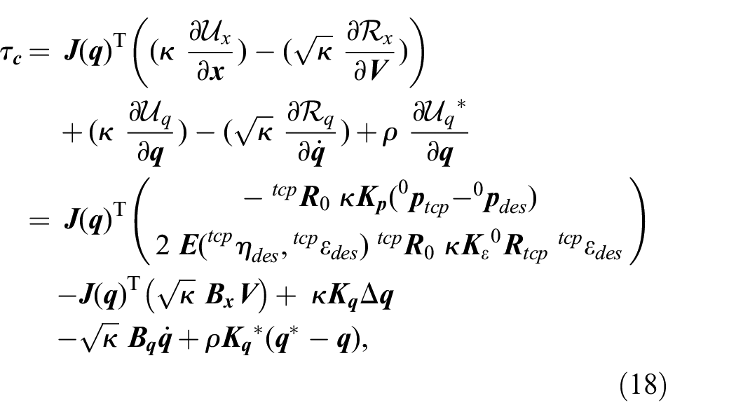
where
A great benefit of this general approach is that the scaling functions can be applied no matter how the elastic potential is described. Hence, the presented controller is a feasible extension for every impedance controller. Moreover, in the presented version, the scaling parameter
3.4 Derivation of a safe energy budget
ISO/TS 15066 provides energy thresholds that can be calculated via
With the minimal force values and stiffness parameters of Table 1, the energy thresholds can be calculated for our example application (Table 2).
Bio-mechanical energy thresholds based on ISO/TS 15066, for affected body parts in the example application. The bold numbers indicate the lowest values that have to be taken into account.
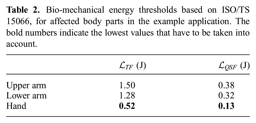
These values determine the limit to the bio-mechanical energy that can be exchanged during the transient (
As can be seen in Figure 11, the robot automatically limits
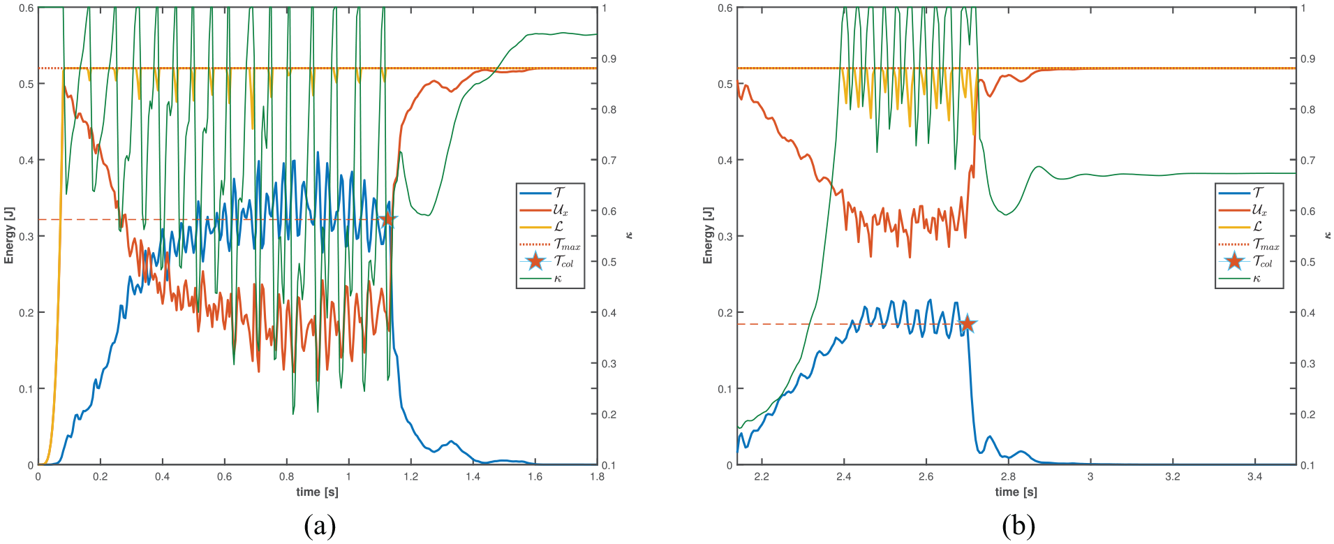
Energy distribution with active scaling function during (a) transfer motion and (b) approach motion. Once the threshold
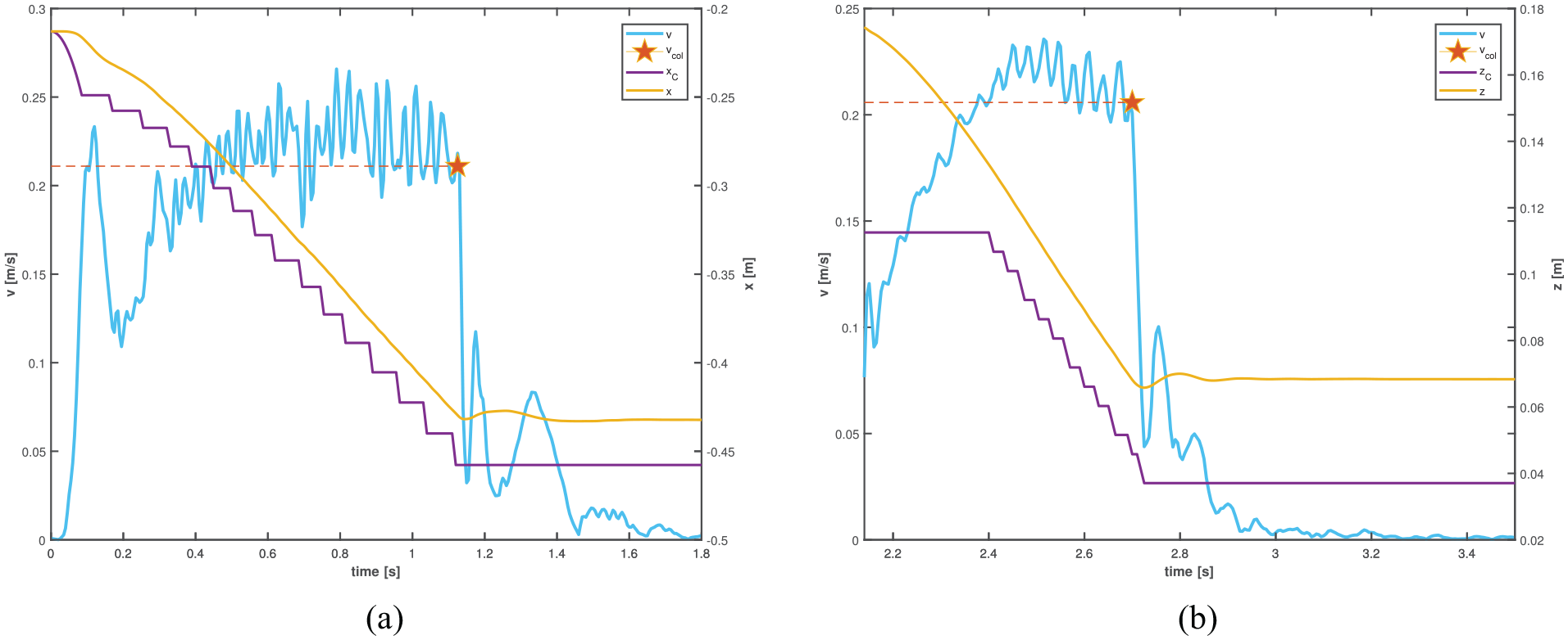
Velocity and position with active scaling during (a) transfer motion and (b) approach motion. The robot velocity quickly reduces after the first collision instant (
During the transient contact phase,
During the quasi-static contact phase, the potential energy imposes a clamping force. The calculated energy threshold based on ISO/TS 15066 for this phase is
Force and pressure distribution with active scaling function during (a) transfer motion and (b) approach motion. The maximal transient force values (
The classical approach showed large differences between measurements with rounded and sharp objects. During the transient contact phase with gripper cover and gripper jaw, the maximum transient force values were
4. Conclusion
Our first aim was to make the reader aware of the influence of coordinates on the implementation of safety measures in pHRI applications. We have reviewed the current certification process with an example application on a real robot. Coordinate frames had to be placed on the robot structure to monitor Cartesian velocities. With collision measurements, the velocity was iteratively adapted until no bio-mechanical thresholds were violated. For a poor choice of coordinate frame positions, unmonitored high velocities present risks if unintended collisions occur. If joint torque sensors are used to detect collisions, the reliability of the detection depends on the current robot configuration.
Our second aim was to present a novel approach that removed these limitations by assigning an energy budget for impedance controlled robots. This coordinate invariant control approach facilitates the certification process of pHRI applications. The key features of this control approach are as follows.
The energy budget is a coordinate invariant quantity that acts on the whole robot. No coordinate frames have to be placed on the robot structure. For kinematically redundant robots, fast nullspace motions are reduced automatically.
The detection of collisions is independent of the current robot configuration. No external sensors are needed.
The controller can be used for all contact scenarios. The transferred energy during transient contact is limited to a maximal threshold. This energy scaling method eliminates high static forces in clamping scenarios.
During contact, the robot is compliant. If the robot is pushed, its energy threshold is still guaranteed. After contact, the robot automatically continues to move on its pre-planned trajectory.
This new approach facilitates the current certification process: instead of adapting multiple control parameters, the presented approach has one control input
4.1 Limitations of the proposed approach
A practical limitation of the presented approach is its need for accurate dynamic model data for the robot. Without access to
The energy threshold
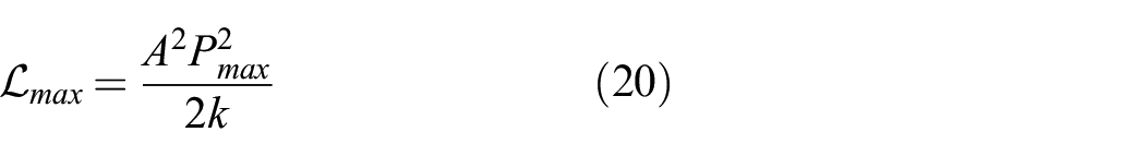
Compared with (19), in this case
Many pHRI applications involve contact, e.g., during assembly processes. These processes might involve potential energy greater than
Lightweight robots have low inertia and, hence, low kinetic energy during movement, which is a beneficial factor for the transient contact phase (De Santis et al., 2008). Therefore, the presented work is a promising control approach for these kind of robots. Classical industrial robots, however, move high masses and therefore have limited application to pHRI. For these robots, external safety measures are needed that monitor the distance between the robot and the human.
4.2 Critical review of current certification process
In this article, we have shown the current certification steps of robot applications with pHRI. One important step was to select the correct body part. This step is crucial, because a wrong choice of body parts could yield hazards that traditional safety measures could not cover. However, for applications with unstructured environments it is challenging to predict all possible collision scenarios and respective body parts in advance.
In ISO/TS 15066, force and pressure values are the main parameters to make a statement about the safety of a collaborative application. For the robot transfer motion in our example application, the force and pressure values were in accordance with ISO/TS 15066. However, the end-effector traveled a large distance from the first collision instance to the stopped position. This distance was not considered, even though it could represent a risk for the human co-worker. Imagine if an obstacle had been placed in the workspace; the human co-worker would have no means to back-up.
In case a safe distance is violated, classical industrial robots have to stop as quickly as possible. As clamping risks are excluded, this is a safe reaction. For pHRI applications, however, extensive care has to be taken to minimize the contact force and pressure during clamping scenarios with the stopped robot. For collaborative robots, we submit that the definition of a safe reaction in current standards and regulations should be reviewed and revised, i.e., in ISO/TS 15066, ISO 10218-1, and ISO 10218-2. Moreover, we conclude that for pHRI only a compliant robot reaction is a safe reaction because it eliminates the clamping risk and does not evoke a new risk caused by an active robot reaction after a collision.
Footnotes
Appendix A. Index to multimedia extensions
Archives of IJRR multimedia extensions published prior to 2014 can be found at http://www.ijrr.org, after 2014 all videos are available on the IJRR YouTube channel at http://www.youtube.com/user/ijrrmultimedia
Experiments on a real robot: classical versus novel approach
Appendix B. Set-up for collision measurements
Appendix C. Controller parameters
To verify the energy budget calculated with the thresholds of ISO/TS 15066, the controller of Section 3.2 has been implemented with initial control parameters as follows:
The desired control motion is dependent on
Acknowledgements
We would like to thank KUKA Systems GmbH for providing us the measurement equipment. A special thanks goes to Florian Groschup and Nicolas Brueckmann.
Funding
This work was partially funded by the MURAB project (grant agreement number 688188). N. Hogan was supported in part by the Centers for Mechanical Engineering Research and Education at MIT and SUSTech.