
Abstract
We present an approach for the verification and validation (V&V) of robot assistants in the context of human–robot interactions, to demonstrate their trustworthiness through corroborative evidence of their safety and functional correctness. Key challenges include the complex and unpredictable nature of the real world in which assistant and service robots operate, the limitations on available V&V techniques when used individually, and the consequent lack of confidence in the V&V results. Our approach, called corroborative V&V, addresses these challenges by combining several different V&V techniques; in this paper we use formal verification (model checking), simulation-based testing, and user validation in experiments with a real robot. This combination of approaches allows V&V of the human–robot interaction task at different levels of modeling detail and thoroughness of exploration, thus overcoming the individual limitations of each technique. We demonstrate our approach through a handover task, the most critical part of a complex cooperative manufacturing scenario, for which we propose safety and liveness requirements to verify and validate. Should the resulting V&V evidence present discrepancies, an iterative process between the different V&V techniques takes place until corroboration between the V&V techniques is gained from refining and improving the assets (i.e., system and requirement models) to represent the human–robot interaction task in a more truthful manner. Therefore, corroborative V&V affords a systematic approach to “meta-V&V,” in which different V&V techniques can be used to corroborate and check one another, increasing the level of certainty in the results of V&V.
1. Introduction
Robotic assistants that interact with people in an informal, unstructured, and complex manner are increasingly being considered for industrial and domestic domains. In manufacturing, the drive toward more flexible production, quality, and consistency in the production, and the reduction of tiring and dangerous tasks requires that humans work near robots, or even teach and physically interact with them as co-workers.
A way to enhance robots, to allow their safe and trustworthy participation in human–robot interactions (HRI), is the incorporation of safety and fault recovery mechanisms at all levels, from low-level mechanical systems and basic controllers to higher-level decision-making systems (Alami et al., 2006; Pipe et al., 2011). For example, restricting motion when near humans has been applied as a low-level safety solution (Pedrocchi et al., 2013). However, to allow robot assistants to transition from research laboratories and very limited application scenarios (such as surveillance, transport or entertainment) to the broader domestic and industrial domains, they need to be demonstrably trustworthy (Eder et al., 2014). Collaborative robots will also need to conform to recent standards, e.g., ISO 10218-1:2011 (2011), ISO 13482:2014 (2014), and ISO/TS 15066:2016 (2016). Thus, HRI requires the development of coherent and credible frameworks for V&V.
A major challenge in V&V of robot assistants is that no single technique is adequate to cover the whole system in practice. “Correct” functioning in an HRI scenario is likely to depend on precise physical details, as well as complex high-level interactions. Individually, formal methods, such as model checking and theorem proving, simulation-based testing, or experiments in real-world scenarios, cannot examine the entire state space of the interaction with realistic detail. The advantages of these techniques—formal, simulation, and experiments—in terms of coverability (i.e., the exploration of the state space, such as combinations of human–robot actions or motion ranges) and realism can be exploited when combining them.
Combining V&V techniques in the HRI domain yields an additional benefit—trust in the correctness of V&V results. When using a single V&V technique, this is hard to achieve. System models used in formal methods or simulation-based testing, and requirements models, are subject to manual input errors, despite efforts in automating translations between models and translations from code to models. The use of complementary V&V techniques can highlight discrepancies and help system developers gain confidence in the resulting evidence about safety and liveness requirements.
1.1. Our contribution
Our contribution, presented in this paper, is twofold:
To propose an approach to the verification and validation of robots and autonomous systems that allows different V&V techniques to corroborate one another, and where the outcomes from applying one technique are used to improve the other techniques. This approach, called corroborative V&V, provides a greater degree of certainty in the V&V results than would be found in using the V&V techniques individually.
To demonstrate the effectiveness of corroborative V&V by applying it to the most critical part of a collaborative manufacturing HRI scenario, the robot-to-human handover task.
In this paper, we combine formal methods, simulation-based testing, and user validation through experiments with a real robot, in the context of HRI. If the evidence agrees when verifying and validating the same requirement through the three techniques, we will be more confident in the results. Otherwise, an iterative process is used to refine and improve the truthfulness of the assets, the system, and requirement models underpinning each technique. Hence, corroborative V&V provides increased confidence in the evidence, compared with using V&V techniques in isolation. At the same time, by enabling V&V to span across several levels of detail or abstraction, our approach provides a thorough exploration of the robot’s range of behaviors, thus overcoming limitations of individual V&V techniques.
The proposed approach is exemplified through an object handover task, the most critical component of a cooperative manufacture scenario, for the BERT 2 robot (Lenz et al., 2010). We formulated safety and liveness requirements based on relevant standards. We then used this case study to show that corroborative V&V can provide a greater degree of confidence than when using V&V techniques in isolation. The instantiation of our approach for the case study comprises, as V&V techniques, probabilistic model checking in PRISM (Kwiatkowska et al., 2011), simulation-based testing in ROS (Open Source Robotics Foundation, 2019) and Gazebo (Open Source Robotics Foundation, 2014), and an experimental setup in the Bristol Robotics Laboratory.
A formal model comprising probabilistic timed automata was constructed by hand, representing the HRI. Probabilistic computation tree logic (PCTL*) (Kwiatkowska et al., 2011) properties were derived from the requirements, to be verified against the formal model. We developed a simulator in ROS–Gazebo, with the real code for the robot and a simulated human co-worker. Tests were derived from model-based and pseudorandom techniques, as in our previous work (Araiza-Illan et al., 2015, 2016), to stimulate the HRI components toward checking the satisfaction of the requirements. Automated checkers implemented as assertion monitors, as described in our previous work (Araiza-Illan et al., 2015, 2016), were also derived from the requirements and added to the simulator. Applying the complementary V&V techniques exposed discrepancies in the resulting evidence, allowing the assets to be examined and refined. Iterating over this process led to agreement between the three techniques, thus providing greater confidence in the correctness of the resulting evidence and the suitability of subsequent design recommendations.
The paper proceeds as follows. Section 2 presents the corroborative V&V approach, outlining the V&V techniques, their corresponding assets to be developed from the HRI system and its requirements, and their interactions to gain confidence in the resulting evidence. We then introduce the case study, the handover task, and the requirements to be verified in Section 3. Next, we present the instantiation of the proposed corroborative V&V approach for the case study in Section 4, including the development of assets comprising the formal model, the simulator, and the translations of the requirements into logical properties and assertions. We present the V&V results for two of the proposed requirements in Section 5, describing in detail the encountered evidence discrepancies, with the consequent asset refinement and improvement processes until a high degree of corroboration between the V&V results is reached. In Section 6, we then demonstrate V&V of the remaining requirements using the three V&V techniques. Section 7 discusses the findings and limitations in the application of the corroborative V&V approach to our case study. In Section 8, we compare our approach to others in the literature, highlighting how corroborative V&V provides a novel V&V framework and complements existing approaches. Finally, we offer conclusions and directions for future work in Section 9.
2. Corroborative V&V
As noted in the introduction, corroborative V&V provides a thorough exploration of the robot’s range of behaviors across different levels of abstraction, thus overcoming limitations of individual V&V techniques. Our approach to the V&V of human–robot teams is shown in Figure 1. We propose the combined use of a number of techniques to verify and validate robots in HRI tasks, which are shown in ellipses. Each technique is underpinned by two assets: a requirements model, shown in a rectangle, and a system model, shown in an octagon. In this paper, we focus on the use of three particular V&V techniques, but other methodologies can be integrated into the corroborative V&V process if required. This is discussed in more detail in Section 7.1. We introduce the techniques, the assets, and the corroborative V&V workflows, indicated by the arrows in Figure 1, in the following subsections.
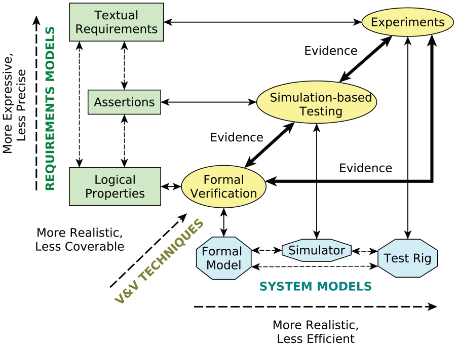
Framework for corroborative V&V.
2.1. V&V techniques
Formal verification encapsulates a set of mathematical techniques, which are used to prove properties about a formal model of a system. Some of the most common formal verification techniques are model checking (Clarke et al., 1999) and theorem proving (Fitting, 1996). In this paper, we use model checking, which lets us verify that formal models (which represent the robot and its non-deterministic environment) satisfy temporal logical properties (derived from requirements) for every possible way in which the models can be executed. As we examine every possible execution of the formal model, we can demonstrate whether or not the model satisfies the temporal logical properties.
In “traditional” model checking, finite state machines are modeled and explored exhaustively in order to determine whether some property holds (Clarke et al., 1999). Properties are typically expressed as logical formulas written in a logical language, e.g., linear-time temporal logic or computation tree logic. The output of a model checker is typically a Boolean value, true or false, indicating whether the model satisfies a given property. Where the model does not satisfy the property, an “error trace” or counterexample is output, describing the sequence of states that led to the violation of the property (Fisher, 2011). Probabilistic model checking, explained further in Section 4.1, extends this method to allow the computation of the probability that a given property will be satisfied.
Simulation-based testing involves running a simulator under different inputs (or tests), to observe the resulting outputs and determine whether the simulated system behaves as intended. Software and hardware components can be modeled to achieve an appropriate compromise between realism, modeling effort, and computational cost, and real code can be run. Nonetheless, the exploration of a system under test is not exhaustive. Systematic methodologies to explore the system under test, such as coverage-driven verification (Araiza-Illan et al., 2015, 2016), should be used to increase efficiency and effectiveness under computational constraints. A coverage-driven verification testing process needs testbench components, including a test generator and a driver, to stimulate the system under test, a coverage collector, to keep track of the V&V progress, and a checker, which models the requirements and automates the checking (Piziali, 2004).
Experiments are performed within a test rig to verify and validate robots interacting in realistic environments with respect to textual requirements. As experiments often involve human volunteers, health and safety assessments, and expensive equipment, the number of times that a particular scenario can be examined is often severely limited, compared with simulation or formal verification. In this paper, experiments are focused toward achieving clear evidence on the principal requirements, as well as to ground the corroborative V&V process in reality.
The diagonal axis in Figure 1 arranges the three techniques based on how realistic and how coverable they are, where coverability refers to how much of its asset a technique can analyze. Note that there is generally a trade-off between realism and coverability. Formal verification (e.g., using a model checker) can exhaustively check the entire state space of a formal model (Clarke et al., 1999), while simulation-based testing only samples the state space of a simulation model. However, a simulation model is able to better account for physical details that are difficult to capture in a formal model, such as physical dynamics, and is therefore able to more realistically model the actual system. Physical experiments are even more realistic, but the number of experiments that can be performed will probably be significantly lower than the number of simulations that can be performed, since experiments are more heavily constrained by time and other resources. Additionally, physical experiments can be adversely constrained by ethical or safety concerns, which are not an issue in simulation-based testing and formal verification.
2.2. V&V assets
In Figure 1, it is shown that requirements can be modeled in a number of ways. Textual requirements are the written requirements that describe the desired behavior of a robot and can also include some assumptions about the human user’s behavior and the environment in which the robot operates (e.g., materials required to complete the task are available at the start). Textual requirements are used in experiments to determine whether the robot (i.e., the physical system) satisfies them. Textual requirements for robots are typically based on the needs of the system’s users but are increasingly based on legal or ethical frameworks specified by a regulatory or standards authority. For example, ISO/TS 15066:2016 (2016) defines many safety requirements for collaborative robots. In practice, verifying a textual requirement in experiments may necessitate refinement of the text with consideration of the actual scenario, to avoid ambiguities.
Assertions are requirements of a system expressed in an assertion specification language using the syntax of programming languages such as C or Python (Foster et al., 2004), or as assertion monitors, such as the ones implemented in Araiza-Illan et al. (2015, 2016) and Huang et al. (2014a). Assertions are commonly formulated in a precondition-implies-postcondition manner, and can be implemented directly in the code under testing, or within the simulation models. Tools are available to convert temporal logical properties into monitors for runtime verification, as in Havelund and Rosu (2002) and Huang et al. (2014a), the latter for testing robots. The systems under verification are stimulated to attempt to trigger the preconditions in the assertions and consequently their respective postconditions. The outcomes of these checks are interpreted to determine whether the requirements are satisfied.
A software simulator, usually written in a high-level programming language, contains models of the robot’s behavior as well as its environment. In simulation-based testing, the simulator program is executed a number of times (computation time allowing), to collect information from the assertion checks and the simulation itself. As mentioned in the introduction, a number of both open source and proprietary simulation and development frameworks exists in robotics, such as ROS, Player/Stage, Gazebo, V-REP, and Webots.
Logical properties are logical statements, each of which captures one or more requirements of the system using some formal logic. Different logics can be used for different applications; e.g., if we want to capture requirements relating to time, we might use linear temporal logic (Fisher, 2011). Alternatively, if we are interested in the probability of the requirement being met, we might use PCTL*. Formal modeling tools specialize in supporting particular types of formal model and temporal logic, such as PCTL* by PRISM (Kwiatkowska et al., 2011). Formal models are discrete computational descriptions of high-level behaviors. Finite state automata (Clarke et al., 1999) and probabilistic timed automata (Parker, 2016) are two examples.
Figure 1 arranges the requirements models in order of how expressive or precise they are. “Expressivity” here indicates the breadth of realism that could be referred to in the requirement model, while “precision” refers to how specific the expressions may be. A single requirement may be implemented as assertions in many ways, e.g., according to interpretations by different programmers. As assertions are based on programming languages, whose semantics are more well-defined than natural languages, we consider assertions to be more precise than textual requirements. Logical properties are, in turn, more precise than assertions and textual requirements, as they have precise, mathematical definitions. Conversely, assertions can be more expressive than logical properties, as they can capture aspects of the system that are difficult to specify at higher levels of abstraction (e.g., physical states that depend on modeled dynamics). However, the assertions are less expressive than the textual requirements: subjective requirements, such as user satisfaction, are difficult to model in programming languages. It should also be noted that the more realistic levels of the framework can support a broader set of requirements, since they allow the monitoring of parameters or the analysis of components that might not be available in more abstract models.
Ideally, the assets mentioned before would be generated during the development of the robot itself. For example, textual requirements would be developed at the start of the traditional product engineering life cycle and might be based on standards and regulations, such as ISO 10218-1:2011 (2011) for industrial robots. At the next stage in the life cycle, the product would be designed. Simulation and formal analysis are often used in the hardware and software domains at the design stage in order to gain confidence in the correctness of the design with respect to the specifications. Hence, formal models and simulators would be developed. This practice can be adopted for the design of robot assistants, as demonstrated by Kirwan et al. (2013) for autonomous navigation. Experiments would be performed during implementation of the robot system in real-life HRI, after designing the corresponding setup. If it is not possible to develop all assets during the initial development of the human–robot system—e.g., if the human–robot system has already been developed—the approach can still be applied. In this case, it is necessary to develop assets based on existing materials.
Re-examining equivalent requirements implemented at different abstraction levels of the framework provides an opportunity to refine individual assets to represent the HRI more accurately and truthfully, making the framework robust with respect to human error and providing a high degree of confidence in the resulting evidence. When refining the assets, complexity needs to be carefully managed, e.g., through abstraction. Re-modeling formal models and simulators can result in a state space explosion and a significant increase in time and memory (Clarke et al., 2012). As explained previously, each level of our framework represents a different compromise between realism and the coverability of the state space. Any decisions affecting the balance of this compromise should be made by those conducting the V&V.
The bidirectional arrows between the different system models in Figure 1, and between the different requirements models, indicate that the development of any of these models may be informed by the equivalent model at another level of abstraction. Such development may be carried out manually or by using some of the techniques mentioned in Section 8. Our framework allows for the incorporation of such techniques to suit the application in question.
2.3. Workflows
Our approach leaves open the order in which the different V&V techniques in Figure 1 should be used. Such decisions should be made with consideration for the specific HRI application in question. Furthermore, these decisions will typically be made in a reactive manner, because insights gained from any of the techniques can lead to modifications in any of the system models or requirements models, necessitating a further stage of V&V to increase confidence in the results, possibly with a different technique.
For example, we could start with a set of logical properties and a formal model of the robot system. Formal verification would then be used to verify that the formal model satisfies the logical properties. This process is indicated by the arrows from “Logical Properties” and “Formal Model” to “Formal Verification” in Figure 1. The result of formal verification is evidence that the formal model is correct with respect to the logical properties. During this V&V, we might discover that the formal model does not satisfy a particular property. If we trust this V&V result, modifications to the formal model could be an appropriate way to explore possible design modifications. The “Simulator” and “Test Rig” would then need to be updated accordingly, as represented by the bi-directional dashed arrows between system models in Figure 1. Alternatively, the property violation may be due to an error in the model or in the logical property (i.e., we have incorrectly formalized a requirement). We may wish to revise the properties or formal model (or both) manually if the fault lies there. This is indicated by the arrows from “Formal Verification” back to “Logical Properties” and “Formal Model.” Similarly, we might wish to gain more confidence in the correctness of the formal model and logical properties by employing one of the other V&V techniques, before proceeding to modify the real system and the other assets.
The same requirements, implemented as assertions, could then be monitored during simulation-based testing, providing more V&V evidence. This technique is indicated by the arrows from “Simulator” and “Assertions” to “Simulation-based Testing.” During testing, we might find requirement violations, as we did with formal verification, and we would then have to decide a course of action: revising the relevant assets (e.g., the simulator or the assertions), or proceeding to compare the results with experiments to gain more confidence, if results were similar to formal verification. (The comparison between the outputs of the V&V techniques is indicated by the bold arrows in Figure 1.) Conversely, evidence generated by the simulation might not align with evidence generated by the other V&V techniques, resulting in a lack of corroboration. There are a number of potential causes of such disagreements:
System model inaccuracies. All the V&V techniques use models of the real world. The models might have been constructed erroneously or might be inconsistent with the real world, or relative to one another.
Requirement model inaccuracies. In our approach, the real-world requirements of the system are converted into textual requirements, assertions, and properties for V&V. These requirements models might not have been correctly formulated.
Tool inaccuracies. It is possible that numerical approximations affect the V&V results. In addition, third-party tools can contain bugs that are unknown.
We could now proceed to perform “Experiments.” As before, we might find a problem with the textual requirements or the robot’s test rig during experimentation. At the same time, the evidence from formal verification or simulation-based testing can be compared against the experiment results. We might also discover that one of the requirements is satisfied during simulation-based testing or formal verification but not during the experiments. In this case, we might need to refine any of the other assets, as explained before.
Careful comparisons must be made between the different representations in order to discover the cause of the conflicts. Such comparisons are indicated by the bi-directional bold arrows between “Formal Verification” and “Simulation-based Testing,”“Simulation-based Testing” and “Experiments,” and “Formal Verification” and “Experiments,” respectively, in Figure 1.
3. The BERT handover task: A case study
Corroborative V&V can be used to provide a higher degree of confidence in the V&V evidence than when using V&V techniques in isolation. In this section, we present an (intentionally) simple HRI case study to demonstrate this. The corroborative V&V of a more complex case study would have been difficult to fully explain within the bounds of this paper. It was thought preferable to cover a simpler scenario in a great amount of detail, rather than a more complex HRI scenario in less detail. Nevertheless, corroborative V&V might be applied to more complex scenarios than the one presented here.
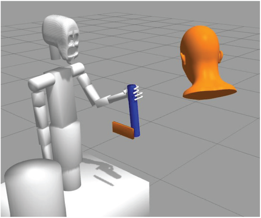
Despite its simplicity, our HRI case study concerns robot-to-human handover, the most critical part in a human–robot collaborative manufacturing task. The case study uses BERT 2, an upper-body humanoid robot designed to facilitate research into complex human–robot interactions, including verbal and non-verbal communication, such as gaze and physical gestures (Lenz et al., 2010) (see Figure 2). BERT 2’s software architecture was originally developed using YARP (YARP, 2019). More recently, this system has been wrapped with a ROS interface.
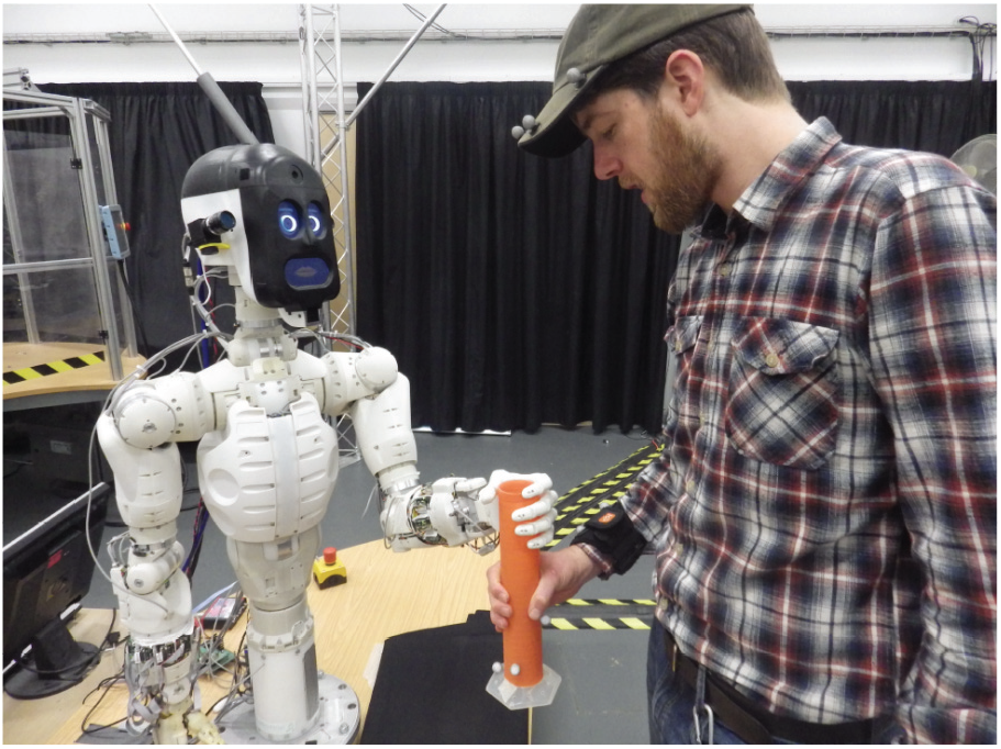
BERT 2 in the handover task test rig. Video available at multimedia Extension 1.
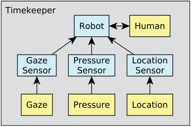
We verify an object handover to exemplify our approach, in the context of a broader collaborative manufacture scenario where BERT 2 and a person work together to assemble a table (Lenz et al., 2012). In the handover, the first step is an activation signal from the human to the robot. BERT 2 then picks up a nearby object and holds it out to the human. The robot announces that it is ready to handover. The human responds verbally to indicate “ready to receive.” (For practical reasons, human-to-robot verbal signals were relayed to the robot by pressing a key.) Then, the human is expected to pull gently on the object while looking at it. BERT 2 then calculates three binary sensor conditions:
Gaze. The human’s head position and orientation relative to the object are tracked using the Vicon® motion-tracking system for an approximate measure of whether he or she is looking at the object.
Pressure. Changes in the robot’s finger positions are sensed to detect whether the human is applying pressure to take the weight of the object.
Location. The Vicon® motion-tracking system is used to determine whether the human’s hand is located on the object.
The sensor conditions must be calculated within a time threshold for BERT 2 to determine whether the human “is ready.” The robot should release its grip on the object if all three conditions are satisfied. Otherwise, the robot should terminate the handover and not release the object. The human may disengage and the robot can time out, which would cancel the remainder of the handover task. The sensors are not completely accurate and might sometimes give incorrect readings.
3.1. System requirements
A safety requirement ensures that “nothing bad happens,” whereas a liveness requirement ensures that “something good happens eventually” or inside a threshold of time, for practical reasons (e.g., in simulation). The requirements for any HRI task depend on its safety and functional context. For example, in our case study the robot would need to achieve a particular handover success rate threshold to keep up with manufacturing throughput or avoid unacceptable damage costs, as per the users’ requirements. We considered two different thresholds for our first functional requirement, based on estimates of acceptable productivity in two different settings. The first threshold is considered for deployed use in a hypothetical manufacturing environment.
Requirement 1a. At least 95% of handover attempts should be completed successfully.
In a research and development environment, a lower threshold may be considered satisfactory to provide proof-of-concept, showing that the system works most of the time.
Requirement 1b. At least 60% of handover attempts should be completed successfully.
The following requirements were chosen to illustrate our approach, inspired by Grigore et al. (2011) and drawing from standards ISO 10218-1:2011 (2011) for industrial robots, ISO 13482:2014 (2014) for personal care robots, and ISO/TS 15066:2016 (2016) for collaborative robots:
Requirement 2. If the human is not ready, the robot shall not hand over the object.
Requirement 3. If the human is ready, the robot shall hand over the object.
Requirement 4. The robot always reaches a decision within a threshold of time.
Requirement 5. The robot shall always either time out, decide to release the object, or decide not to release the object.
Requirement 6. The robot shall not close its hand when the human is too close.
Requirement 7. The robot shall start at restricted speed.
Requirement 8. If the robot is within 10 cm of the human, the robot’s hand speed is less than 250 mm/s.
These requirements are ambiguous in terms of how they are assessed over the available system information, reflecting the generality of the standards and the shortfalls of using natural language when first establishing requirements. To verify and validate them, we need to interpret them in terms of available variables and system behaviors according to the assets.
4. Corroborative V&V of the case study
After establishing the system’s requirements, we developed a plan for the application of corroborative V&V to the case study. We chose to focus on a “typical use case” for the handover task, in which the human has a working familiarity with the robot and intends to complete the task successfully. Any of the requirements may be used as bases for comparison between techniques used, provided that the requirement may be modeled at all levels of abstraction. We chose to focus on our principal functional requirements (requirements 1a and 1b, concerning the handover success rate) as a first basis for failure finding and to refine the assets if necessary. The handover success rate could be expected to be sensitive to a wide range of foreseen and unforeseen events. As a scalar measure, it allows evidence from the V&V techniques to be compared in a quantitative manner, whereas comparisons of Boolean results might be insensitive to important modeling discrepancies.
After focusing on requirements 1a and 1b, we proceed to verify the remaining requirements (requirements 2–8), identifying any further need to improve assets or the system itself. The V&V of the full set of requirements provides a more comprehensive evaluation of the system’s requirement satisfaction, while facilitating the evaluation of the benefits of combining individual V&V techniques to complement one another.
As mentioned in Section 2.3, corroborative V&V will be carried out in a reactive manner according to the resulting evidence. In terms of the order in which we applied the V&V techniques, we chose to begin with a comparison of formal verification and simulation-based testing for requirements 1a and 1b, to acquire as much insight as possible into the system and our modeling assumptions before committing resources to more expensive physical experiments. The subsequent stages of V&V and asset modification, explained in Section 5, were conducted with the aim of achieving agreement on the handover success rate (requirements 1a and 1b) that was corroborated by all three V&V techniques.
To apply our approach to the BERT 2 handover scenario, it was necessary to implement each element in Figure 1. Appropriate tools for formal verification and simulation-based testing were selected first. Requirements models were then translated from the textual requirements in Section 3, and system models were constructed to reflect the physical system. We developed relevant assets for a chosen set of tools, comprising the probabilistic model checker PRISM, ROS–Gazebo and a coverage-driven verification testbench for simulation-based testing, and experiment designs at the Bristol Robotics Laboratory. We detail the development of these components in the following subsections.
4.1. Formal verification
We chose
Properties to verify can be expressed in a probabilistic logic such as PCTL* (Baier and Katoen, 2008). Rather than outputting a Boolean value,
4.1.1. Formal model
The
Inter-module communication within the P
The model consists of around 300 lines of
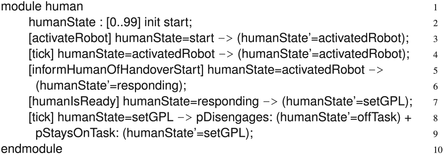
The human module written in
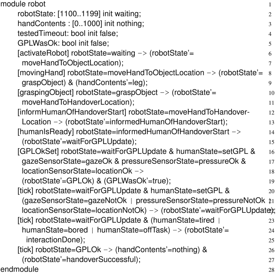
The robot module written in
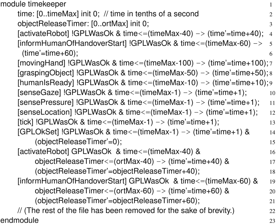
An excerpt from the timekeeper module written in
The
Lines 3–9 are transition rules, which determine how the state of the human module changes over time. For example, the first rule (see line 3) says that if the human is in the state called “start,” then the state is updated to “activatedRobot.” In other words, the first thing the human does in this scenario is to activate the robot for the handover task. The rule also contains a synchronization label, “activateRobot,” which means that this transition must occur at the same time as all other transitions with the same label. In this case, the only other module containing this label is the timekeeper module (Figure 6), as the synchronizations in this model are used primarily to keep track of how much time has elapsed. Another feature of
For our case study, the probability that the human disengages (i.e., becomes bored or distracted) is set to zero as we are examining the typical use case in which the human is always focused on the task. Similarly, we assume that the human’s gaze, hand pressure, and location are always within acceptable bounds for the handover task, i.e., the probabilities that these are acceptable are each set to 1.0. In this model, we are primarily concerned with the robot’s reliability, so we assume that the human is completely reliable and engaged with the task at hand. Note that these probabilities could be set differently if, for instance, we wanted to incorporate the human’s tiredness level in the model, or if we wanted to specify that the person’s interest in the task may waver, affecting gaze and hand pressure and location.
Clearly, the human module only captures the tiny fragment of human behavior that is relevant to the handover sub-task. In more complex HRI scenarios, the human module might have to be much more complex. Indeed, it is extremely unlikely that a PRISM module will ever be able to capture the full complexity and nuance of human behavior. However, it is still desirable, and in fact necessary, for V&V to model the human’s interactions with the robot, even if the model is abstract and coarse-grained.
Real-world sensors do not work perfectly, and this is reflected in the formal model. As a result, it is possible that the handover task will not always complete successfully. The gaze sensor reports that the human is looking at the object only 95% of the time. The rest of the time the sensor reports (incorrectly) that the human is not looking at the object. When the gaze sensor reports correctly that the human’s gaze is okay, the gaze sensor has reported a “true positive.” When the gaze sensor incorrectly reports that the human’s gaze is not okay, we call this a “false negative.” Similarly, the gaze sensor might correctly report that the person is not looking at the object (a true negative, also with probability 95%) or might incorrectly report that the person is looking at the object (a false positive).
The part of the formal model that handles the gaze, pressure, and location sensor states can be seen in lines 16–22 of Figure 5. Note that true positives and their corresponding false negatives are mutually exclusive, and therefore
The pressure and location sensors are given the same probabilities of 95% for true positives or negatives and 5% for false negatives or positives. With no experimental results or hardware specifications to refer to, it was assumed that sensors would be accurate “most of the time.” A reliability of 95% was therefore chosen as a first estimate.
4.1.2. Logical properties
Logical properties, representing requirements, were expressed in terms of PCTL*. We use the following PCTL* symbols (Parker, 2016):
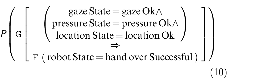
For example, consider requirement 3: “Once the human is ready, BERT 2 will hand over the object.” This requirement can be implemented as a temporal logical formula:
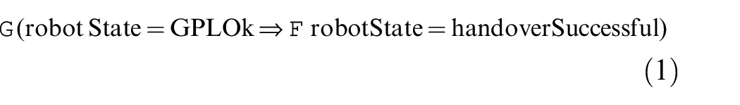
which reads “it is always the case that if gaze, position, and location are correct, then eventually the handover is successful (i.e., the object is released to the human).” We can then find the probability of this formula being true on any given path through the state space. We do this by forming a property in probabilistic computation tree logic (specifically, PCTL*), which can be analyzed using a probabilistic model checker like PRISM:

Using the operation
Another requirement, requirement 1a, is that the probability of completion of the handover task should be greater than 95%. This can be rephrased as, “the success rate of the handover task is at least 95%.” This can be formulated as a property in PRISM as follows:

This property states that the probability that the robot will eventually release the object is at least 0.95, or 95%.
Note that the translation of textual requirements into logical properties is not direct, since there might be different interpretations, depending on the available variables, probabilities, and so on. Hence, this translation process carries the potential for misinterpretation. For example, in properties (1) to (3), “
The full code for the
4.2. Simulation-based testing
A simulator for the handover task was implemented in the ROS framework for robot code development and the Gazebo simulator. Among Gazebo’s features are support for 3D graphics rendering and various physics engines (including ODE (Smith, 2019), used in this paper). Although now available as a standalone Ubuntu Linux package, Gazebo was originally developed as a ROS package and retains its compatibility with ROS. A URDF (universal robot description format) file, used in ROS to describe the kinematic structure of the robot, actuators, and sensors, can simply be extended to describe parameters used by the physics engine, such as inertial properties and friction coefficients. This compatibility allows the same control code to be used in simulations and in the actual robot, providing consistency between simulations, experiments, and deployed use. A screenshot of the ROS/Gazebo simulation can be seen in Figure 7.
Screenshot of the simulated handover task. The human head and hand are represented in orange. The object to be handed over is shown in blue. Video available at multimedia Extension 2.
For the simulator, additional ROS nodes were constructed in Python to simulate BERT 2’s sensor systems and embedded actuation controllers. The pre-existing URDF file describing BERT 2 was extended as described previously for use in Gazebo. The simulated human behavior was controlled by a ROS node written in Python, driving a simplified physical model of the head and hand.
A testbench was incorporated into the simulator. The testbench comprised a test generator, a driver, a checker, and a coverage collector. Exploring meaningful and interesting sequences of behaviors from the robot and its environment in an HRI task is challenging. For this reason, we stimulate the robot’s code in the simulation indirectly by stimulating its environment (e.g., the person’s behavior) instead, and we use a combination of model-based and pseudorandom test generation. Also, to alleviate the complexity of generating and timing different types of system inputs, the test generator is based on a two-tiered approach (Araiza-Illan et al., 2016), where an abstract test is generated first and then concretized by instantiating low-level parameters. The high-level actions of the human in the simulator include sending signals to the robot or setting abstract parameters for gaze, location, and pressure. Low-level parameters include the robot’s initial pose and the poses and force vectors applied by the human during the interaction. For example, we computed an abstract test of high-level actions for the human, by exploring the model in UPPAAL (Uppsala Universitet and Aalborg University, 2015), so that the robot was activated (sending a signal to activate the robot and waiting for the robot to present the object), the gaze, pressure and location sensor readings were correct (set gaze, pressure, and location to mean “ready”), and the robot released the object. This allowed requirement 3, “If the human is ready, BERT 2 should hand over the object,” to be tested.
The driver distributed the test components in the simulator. A self-checker—i.e., automated assertion monitors—was added according to the requirements, described in more detail in the following subsection. Finally, a coverage collector gathered statistics on the triggering of the assertion monitors. The simulator code is available online (GitHub, 2019).
4.2.1. Assertion monitors
For requirements checking, assertion monitors were implemented as state machines in Python, allowing sequences of events to be captured. If the precondition of an assertion is satisfied, the machine transitions to check the relevant postconditions, to determine whether the assertion holds or not. Otherwise, the postconditions are never checked.
For example, requirements 1a and 1b and requirement 3 were both initially monitored as the following sequence:
Note that, as with the logical properties, there may be different ways to implement an assertion for the same textual requirement, and there is scope for misinterpretation.
The results of the assertion checks, if triggered, are collected and a conclusion about the satisfaction of the verified requirements can be drawn at the end of simulation. The number of times each assertion monitor has been triggered in a set of tests can be used as a measure of the coverage achieved by that test set.
4.3. Experiments
BERT 2 can be verified experimentally with respect to the textual requirements using a custom facility at the Bristol Robotics Laboratory, as shown in Figure 2. When seeking to verify the probabilistic properties of a system, the experiments should ideally provide an unbiased sampling representative of the system’s deployed environment. However, some phenomena might be difficult to reproduce naturally in experiments, owing to their rarity, safety considerations, or other practical limitations. Consequently, experiment-based estimates of their likelihood might be inaccurate, as might estimates of dependent properties, such as the overall success rate of the task.
In the case of the handover task, we cannot confidently seek an overall success rate that accounts for the full possible range of conditions relating to hardware, software, the environment, and the human (including mood, anatomy, and level of understanding of the task). Human factors are particularly challenging to test in an unbiased way. This problem can be ameliorated by acknowledging the constraints of the experiments or proactively constraining them to achieve a more reliable characterization of a subset of the system’s state space. The constraints become a part of the resulting V&V evidence. Thus, the experiments deliver an estimate of “success rate within some set of constraints,” instead of an estimate of “overall success rate.” More affordable or coverable V&V tools, such as simulation or formal modeling, may be employed to gain confidence beyond this constrained experiment. Additionally, more detailed experiments may be performed to explore a wider range of human factors affecting the scenario, and to determine the overall success rate of the handover task beyond constraints. This is beyond the scope of this paper, however.
As we were focusing on the “typical use case” of the handover scenario, in which the human has a working familiarity with the robot and intends to complete the task successfully, experiments were constrained accordingly. Each of the 10 subjects was given clear instructions on how to successfully complete the task, followed by a practice session, which ended when the task was successfully completed three times in a row. Subjects were instructed to try to complete the task successfully in each test. All subjects confirmed that they had no physical disability that would affect their interaction with the robot. The robot started each test in a random pose. The object was placed in a fixed location, with random orientation about its vertical axis (thus changing the orientation of the optical markers, potentially affecting sensing of the object or influencing human hand placement on grasping).
Approval for experiments with volunteer subjects was obtained from the University of the West of England’s Ethics Committee beforehand. A large, diverse cohort enables more comprehensive V&V to be carried out, but a cohort of 10 adult volunteers was deemed sufficient for the purpose of demonstrating corroborative V&V. We recruited the volunteers from the Bristol Robotics Laboratory and the local area. Most had prior robotics experience: three were postgraduate robotics students, one was a robotics entrepreneur, four were postdoctoral roboticists. Two had no prior experience of robotics. All subjects signed a consent form prior to participation.
4.3.1. Textual requirements
For physical experiments, requirements 1–3 can be verified in their textual form based on visual observation, informed by video recordings and user feedback as necessary, e.g., to judge whether the human was ready or whether something had gone wrong.
Requirements 4–8 refer to software or physical parameters that cannot be reliably monitored by visual observation. It is therefore appropriate to implement objective monitoring to inform judgments as to whether the textual requirements are satisfied. To this end, ROS’s built-in rosbag package was used to record all sensor readings, actuation signals, robot poses, and high-level control messages sent during each test. Offline monitoring of these requirements was achieved by playing back the recordings while running assertion monitors, as described in Section 4.2.1.
In the case of requirements 6–8, these monitors depended on the robot’s own sensing systems as the best available estimates of speed and spatial relationships. In real-world V&V exercises, independent sensing should be used.
Requirements 4 and 5 refer to the runtime behavior of the robot’s high-level control code. Hence, the monitors used in the simulation may also be applied to the experiment recordings, because the same robot code is used in each case.
All experiment recordings, along with the assertion monitor reports from simulations and experiments, are available from the University of Bristol’s Research Data Repository (Western et al., 2019).
5. Corroborative V&V of requirements 1a and 1b
After generating assets for V&V through different V&V techniques, we can generate corroborative V&V evidence about the handover scenario, according to the plan described in Section 4.
To discover whether the V&V techniques corroborate one another, we compare evidence of the handover success rate (requirements 1a and 1b) from formal verification (evidence E1) and simulation-based testing (E2). Sources of discrepancy are identified and investigated in experiments with the physical system. Experiment-based verification of the handover success rate in the “typical use case” (E3) is then generated. More detailed system characteristics measured during these experiments are used to inform modifications to the simulator, leading to new evidence (E4) that agrees closely with E3. These simulations also reveal a new aspect of the system’s behavior. All insights gained up to this point are then used to inform modifications to the formal model, and the resulting evidence (E5) is found to agree closely with E3 and E4, satisfying our objective of achieving corroboration between the three V&V techniques. The enacted workflow, depicted in Figure 8, is described in detail in the subsequent subsections.
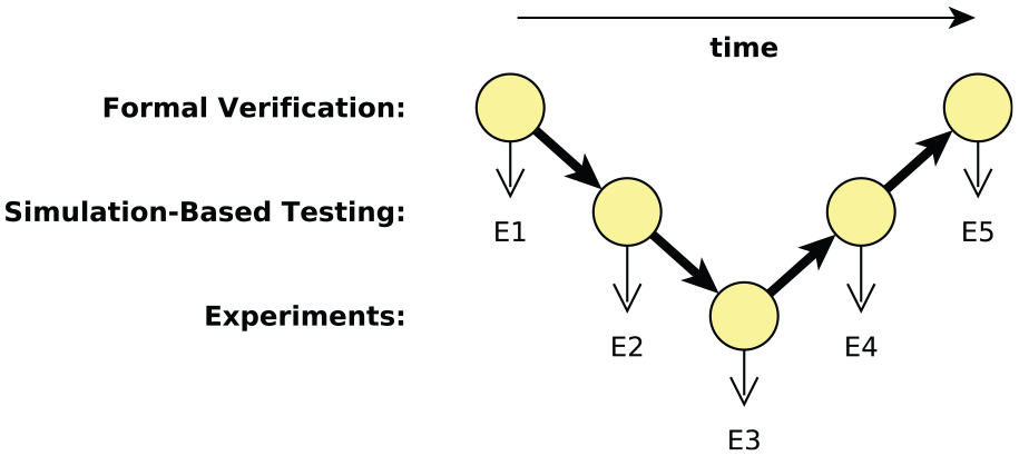
Simplified representation of the corroborative V&V workflow enacted in our case study, denoting the sequence in which evidence items E1 – E5 were produced from individual V&V techniques.
5.1. Formal verification: Evidence E1
As described in Section 4.1.1, the formal model includes probabilities of certain events coming to pass. Using the probabilistic model of the handover scenario, we are able to determine that handover has close to 100% success rate:

That is, almost 100.0% of the time, the handover task completes successfully. This is a very high probability of success, meaning that very few paths through the model result in failure of the handover task. There are two reasons for this. First, the model is based on a typical use case (see Section 4) in which the human’s gaze, hand pressure, and location are assumed to be correct at all times. This reduces the likelihood of handover failure. Second, the robot waits for all of its sensors to report that gaze, pressure, and location are correct before releasing its gripper. If any of these sensors does not report an acceptable value, then the robot continues to wait. This continues until the modeled robot eventually “times out” after 100 s. Given that the human always responds correctly in this version of the model, and there are no other sources of unreliability in the model, the only way the model can fail is if the robot times out while waiting for the sensors to report that the human’s gaze, pressure, and location are within acceptable bounds. As there are far more paths through the model in which the handover completes successfully, the probability of success is very close to 100.0%.
The formal model has shown that BERT 2 satisfies requirements 1a and 1b:
Requirement 1a. At least 95% of handover attempts should be completed successfully.
Requirement 1b. At least 60% of handover attempts should be completed successfully.
However, it is important to note that the formal model is using very rough estimates of the sensor reliabilities. To improve the accuracy of the formal model, it is necessary to find more accurate figures for the sensor reliability. These could be obtained from manufacturer specifications, or through experiments with the BERT 2 robot.
Despite the shortcomings of the formal model in its current form, we can still derive V&V evidence, which we call E1: E1: the success rate of handover is 100.0%.
5.2. Simulation: Evidence E2 does not corroborate E1
Evidence E1 can now be verified by another V&V technique. In this case, we use simulation as it is less costly than experimentation.
Visual inspection of preliminary simulations indicated that the object sometimes fell from the robot’s hand on grasping or during carrying (“grip failure”), a possibility not previously considered. A new assertion monitor was constructed to capture this event in isolation. Additionally, the monitor for requirement 1 was adapted to the following form to account for the possibility of grip failure. Compared with the initial implementation presented in Section 4.2, an earlier precondition is used to trigger the monitor: (
In a set of 100 simulations of the handover task, 80 attempts were then completed successfully. This result forms evidence E2: E2: the success rate of handover is 80%.
Note that E1 and E2 disagree with each other, and are therefore not corroborative. As explained in Section 2.3, there are a number of potential causes of such a disagreement: inaccuracies in either the system models or the requirement models, or in the tools. The latter becomes more unlikely when established tools are used.
In our case, the occurrence of grip failure was clearly the main source of discrepancy. A modeling inaccuracy was present in at least one of the two V&V techniques used: the formal model implicitly assumed a grip failure rate of 0%, whereas simulation indicated 20%. Both the formal model and the simulator assets were modified to account for this, as is shown in the following subsections.
5.3. Experiments: Evidence E3
Before committing resources to user experiments, a set of hardware experiments was conducted to characterize the robot’s actual grip failure rate. BERT 2 was programmed to carry out the grasp-and-carry portion of the handover task 100 times, and grip failure was found to occur in three cases.
At this point, despite some discrepancy, formal modeling and simulation were in agreement that the system satisfied the research-level minimum success rate of 60%. Furthermore, the simulation-based estimate was deemed likely to be conservatively low, owing to the inaccurately high grip failure rate. It was therefore deemed worthwhile to proceed to user experiments.
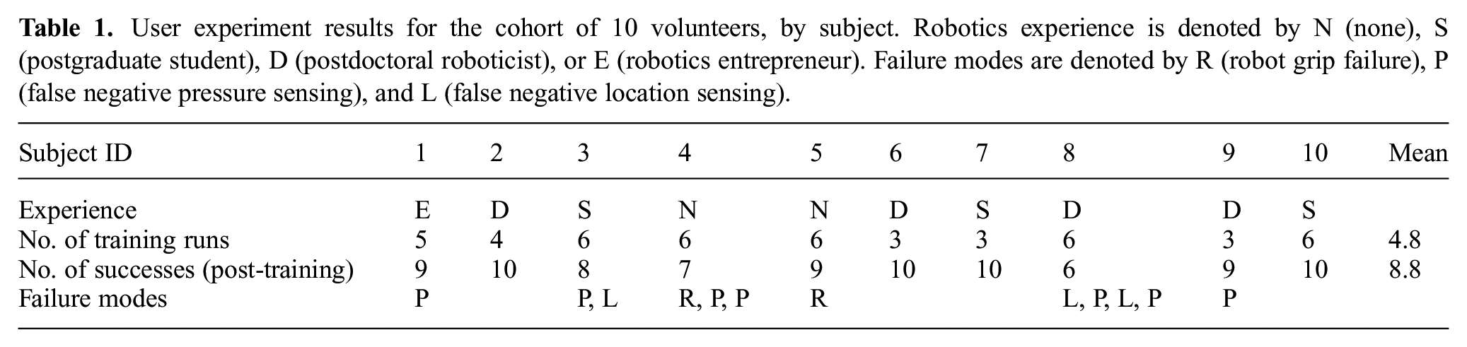
User experiments were carried out as described in Section 4.3. Results are summarized in Table 1. To determine whether it was appropriate to treat our experimental data as independent samples of a single distribution, we investigated whether there was any noticeable effect of learning or prior robotics experience on the outcome of a test. A statistical analysis was performed using IBM® SPSS® v23.0. A Kruskal–Wallis
User experiment results for the cohort of 10 volunteers, by subject. Robotics experience is denoted by N (none), S (postgraduate student), D (postdoctoral roboticist), or E (robotics entrepreneur). Failure modes are denoted by R (robot grip failure), P (false negative pressure sensing), and L (false negative location sensing).
The handover was successfully completed in 88 out of 100 tests. As in simulation, this can be taken as an estimate of the true success rate of the experimental system.
E3: the success rate of handover is 88% in the typical use case.
Here, the “typical use case” is that described in Section 4.3.
Again we found notable disagreement between E3 and the previously generated evidence. A more specific discrepancy had already been identified in terms of the grip failure rate. To seek closer agreement between the three V&V techniques, we explored the potential sources of discrepancy in greater detail.
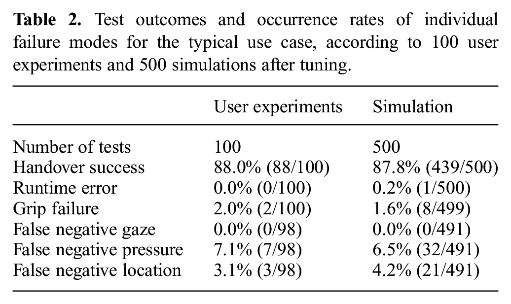
The video recordings and ROS logs, including sensor data, were reviewed to confirm the faults responsible for each failed handover in the user experiments. The failure rate for each failure mode was identified as the number of occurrences divided by the number of opportunities for that fault to occur. The results are listed in the first column of Table 2. “False negative” here was defined relative to the subject’s observable actions. Thus, false negative pressure sensing was identified where the review of logs and videos indicated that the subject was observably applying pressure to the object but the sensing threshold was not exceeded. Similarly, false negative location sensing was identified where the subject’s hand was on the object during the sensing period but the robot’s location sensor returned a negative result. Rates of other possible failure modes (e.g., time outs or false negative gaze sensing) are implicitly estimated to be 0% based on these experiments. This should not be taken as evidence that these modes never occur, only that they are rare. Also, rates of false positive sensor readings could not be defined because, after training, there were no cases in which the subject did not apply their gaze, pressure, and hand location according to the protocol.
Test outcomes and occurrence rates of individual failure modes for the typical use case, according to 100 user experiments and 500 simulations after tuning.
5.4. Modifying the simulator asset
The observed rates for individual failure modes were taken as the best available estimates of those properties in the typical use case and were used to tune the simulator asset (and, subsequently, the formal model asset) to represent that case.
In the previous simulations, the grip failure rate of 20% was clearly much higher than the experimental observation of 3%, while the simulated sensing did not reproduce the other observed failure modes. Several aspects of the simulator were refined with the aim of approximating the experimentally observed rates of individual failure modes without sacrificing realism.
The accuracy of the simulated dynamics of the robot’s handling of the object was improved by replacing default or placeholder values with more realistic estimates of inertial properties, material properties, and joint torque or velocity limits.
The instances of false negative “location” sensing were identified as arising from the motion-tracking system briefly losing track of the object (hand location is measured relative to the object) and reassigning its location to another point. Mimicking this behavior, the simulated motion tracking was set to reassign the observed location of the object (but not the person’s hand or head) to an arbitrary point in 3.1% of readings.
Based on the recordings, all cases of false negative pressure sensing seen in the user experiments were attributed to the subject pulling on the object more gently than in other cases. The exact forcing pattern applied by the subjects could not be extracted from the experiment data. Instead, the lower threshold of the distribution from which the simulated human pulling force was selected was reduced from 5 N to 1 N through a process of trial and error to approximate the failure rate seen in user experiments.
After tuning, a set of 500 simulations was run. In all tests, the simulated human enacted the trace of high-level actions corresponding to the typical use case, remaining engaged in the task and applying gaze, pressure, and location within the relevant bounds. The results, included in Table 2, indicate that the tuning process was successful in approximating the individual failure rates observed in user experiments. Close corroboration is also achieved in the handover success rate, although it must be acknowledged that this correspondence slightly overestimates the true accuracy of the simulator; larger errors are seen in the rates of individual failure modes. Nevertheless, we have improved confidence in the simulation as a representation of the physical system and in the corroborative evidence provided by each V&V technique. E3 is now supported by new evidence from simulation-based testing: E4: The success rate of handover is 87.8% in the typical use case.
Furthermore, the simulations exposed a failure mode not previously considered. In one test, the handover success monitor returned no result and inspection of the logs revealed that the robot’s control code crashed because of a runtime error:
This message indicates that a time out occurred when invoking the robot’s motion planning module. The robot’s high-level control code does not include any means of handling such exceptions. Although rare, these events might significantly affect the user’s trust if they occur in deployment, and could lead to violations of critical safety requirements. In our case, the error caused the only violations of requirements 4 and 5. The exposure of the error, which required high-volume testing and a realistic implementation of the system, demonstrates a key strength of simulation as a complement to formal modeling and user experiments. It is conceivable that the error never occurs in the actual system, e.g., owing to differences in computational load during simulation. However, further testing on the real system cannot rule out the possibility completely. A more conservative approach is to adopt the simulation-based estimate of the error’s frequency as the basis for further corroborative V&V and design recommendations.
5.5. Modifying the formal model asset
Now that we have verified determined simulation evidence E3, we can attempt to corroborate it using formal verification to address the discrepancy discovered between E1 and E3 during the first V&V cycle. As described in Section 5.1, evidence E1 generated by formal verification disagrees with evidence E3, generated by experiments: E1: the success rate of handover is 100.0%. E3: the success rate of handover is 88% in the typical use case.
The formal model currently uses placeholder estimates for the reliability of the gaze, pressure, and location sensors on the BERT 2 robot. However, using some of the experimental data in Table 2, it is possible to replace the corresponding estimates in the formal model with more accurate values. In particular, we can use the following values:
Gaze sensor, false negative: 0.0%;
Pressure sensor, false negative: 7.1%;
Location sensor, false negative: 3.1%.
False negatives and true positives are mutually exclusive, since the former refers to when the person’s gaze, pressure, or location is correct but the sensor reports (incorrectly) that it is not, and the latter refers to when the person’s gaze, pressure, or location is correct and the sensor reports (correctly) that it is. Therefore, we can infer true positive values:
Gaze sensor, false negative: 0.0%, true positive: 100.0%;
Pressure sensor, false negative: 7.1%, true positive: 92.9%;
Location sensor, false negative: 3.1%, true positive: 96.9%.
As the experiments did not report any situations where there were false positives, we assume that the rate of false positive sensor failures is 0.0% for each sensor, and therefore the rate of true negatives for each sensor is 100.0%.
We can now set the probabilities in the model accordingly:
Verifying the model, we can obtain the success rate of the handover task:

It can be seen that the success rate remains at almost 100.0%. This is to be expected, as the sensor failure rates have changed slightly, but it remains the case that the only way for the handover to fail is for the robot to time out.
There is still a significant difference between this success rate and the success rate reported by simulation (87.8%) and experiments (88%). This may be, in part, a result of the way in which the sensors were modeled in the formal model. It was assumed that sensors might make any number of “samples,” while the robot waited for the person to grasp the object in the correct way. Each one of these samples is a separate event, in which the sensor takes a reading that is reported back to the robot’s decision-making system. Therefore, each time the sensor takes a reading there is a probability of failure, and false positives and negatives are possible. The formal model reflects this, and the failure rates given apply to each reading taken by the sensor, rather than the average failure rate per handover. The
The first transition rule says that if the robot is currently waiting for the person to grasp the object (
This way of modeling the handover scenario produces less accurate results when combined with the failure rates established by experiment. This is because the failure rates determined were based on the number of experiments in which, for example, the pressure sensor was seen to give a false negative reading. For example, the probability of 0.071 for a pressure sensor false negative reading was obtained by dividing the number of experiments in which a false negative reading occurred at some point (7) by the total number of experiments not interrupted by gripper failure (98).
Therefore, it would be more accurate to re-model the scenario in a way that reflects experimental reality; that is, the probability of a sensor failure for a handover of the object should be based on the observed average rate of failure of that sensor. This was achieved by modifying the gaze, pressure, and location sensor modules in the
In this revised model, each sensor’s state can be set only once. For example, for the gaze sensor, this is done by introducing a Boolean variable
Verifying the new model gives us a new value for the reliability of the handover task:

The handover task now completes successfully with a probability of 90.0%. This is closer to the simulation and experiment results of 87.8% and 88.0%, respectively, but there is still a noticeable difference. One possible reason for this is that the gripper failure rate, as determined by experiment and built into the simulation, is not yet modeled in
Here, once the robot’s state reaches
Now, one of two things can happen. The first possibility is that the handover completes successfully, as before, with a probability of
Here, “pGripperFailure” is set to 0.02 in accordance with the gripper failure rate of 2% determined by experiment (see Table 2). We verify the model once again to determine a handover success rate of 88.2%:

In a similar way, a new transition was introduced into the transition system to model the possibility of failure of BERT 2’s motion planning module, as described in Section 5.4. This transition occurs at the start of the handover task as the robot prepares to move its arm to grasp the object for handover. The revised transition rule incorporates probabilities for the success or failure of the motion planning module:
These probabilities were based on the data shown in Table 2:
Verifying the model once more gives an updated handover success rate of 88.0%:

Thus, the final evidence provided by formal verification may be stated as: E5: the success rate of handover is 88.0% in the typical use case.
After conducting corroborative V&V of the handover task for the BERT 2 system, it was found that all V&V techniques were corroborative on the probability of a successful handover. The probabilities are shown in Table 3.
Results of corroborative V&V.
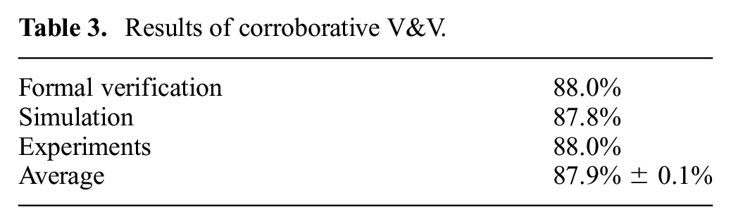
Having established confidence in our models using corroborative V&V, we can assert that in the typical use case requirement 1b is satisfied but requirement 1a is not.
6. V&V of requirements 2–8
In the previous section, we focused our efforts on the V&V of requirements 1a and 1b in order to demonstrate corroborative V&V of a robotic system. However, for the sake of completeness and in line with best practices in engineering, we also attempted V&V of requirements 2–8 using each of the three V&V techniques. These V&V results are presented without reference to corroboration, but corroborative V&V could be applied to requirements 2–8 in a similar manner to requirements 1a and 1b.
It can be seen in the following subsections that the different V&V techniques do not all agree on how well requirements 2–8 are met. This is similar to the case study for requirements 1a and 1b before corroborative V&V. Given enough time, it would be possible to apply the corroborative V&V approach to this expanded set of requirements in order to find the source of the disagreements between V&V techniques and to improve the level of corroboration between them.
6.1. Experiments
For the user experiments, the full set of textual requirements was evaluated through a combination of offline assertion monitoring and visual observation, as described in Section 4.3.1. Table 4 presents the verdicts returned from each individual test. Requirement 1 is included for completeness. Note that for requirements 4–8, up to seven of the missing verdicts were attributable to errors in the recording process rather than the tests themselves.
User experiments: Results on textual requirements from 100 tests. “Covered” indicates the number of tests from which a verdict could be achieved. “Passed” and “Failed” indicate the number of tests in which the requirement was deemed to be satisfied or violated, respectively. “Pass rate” is calculated as the ratio “Passed”:“Covered”.
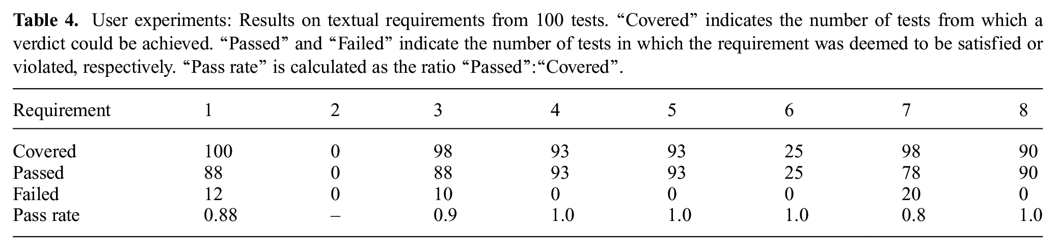
As noted previously, the handover success rate in the user experiments satisfies requirement 1b but violates requirement 1a. Correspondingly, violations of requirement 3 arise from the cases of false negative sensor readings. Additionally, we see that requirement 7 is violated in 78 out of 98 tests; the robot occasionally violates its speed threshold on resetting, presumably depending on its initial pose. A notable “coverage hole” is seen in this test set for requirement 2, as the human was judged to be ready for the handover in every test. All other requirements were covered in at least 25 tests, and no other violations were observed.
6.2. Simulation-based testing
Table 5 presents the results of the assertions monitored in the same 500 simulation-based tests summarized in Table 2, representing the typical use case. Comparing Table 5 with the experiment results in Table 4, we see broad corroboration, but with several noteworthy discrepancies, discussed next.
Simulation: Assertion coverage and results corresponding to each of the requirements (corrected for missing results) in a set of 500 tests.
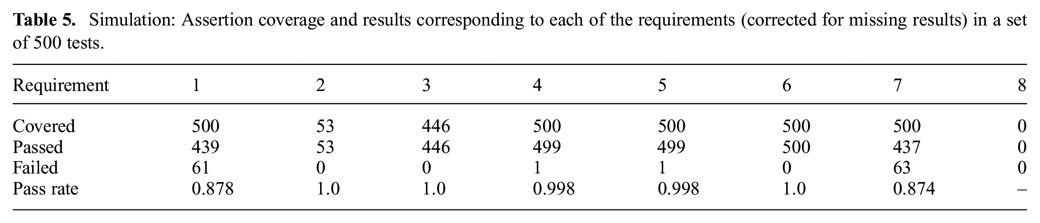
All assertions were covered—i.e., all monitors were triggered at least once—except for requirement 8. This indicates that the human and robot should not come within 10 cm of each other during the interaction. While this is possible given the length of the object to be handed over, the experiments revealed that closer proximities are seen in typical use. Hence, this constitutes a notable coverage hole in these tests.
Contrary to the experiment results, requirement 2 was covered in several tests and no violations of requirement 3 were observed. Further investigation of this discrepancy revealed a potential requirements inaccuracy; the assertion corresponding to this requirement expressed “the human is ready” as
As noted previously, requirements 4 and 5 were violated by the single runtime error. The observation that requirement 7 is violated in 63 out of 500 tests is consistent with the experimental results.
6.3. Formal verification
Requirement 2 says that if the human is not ready, the robot shall not hand over the object. It is formalized as follows:
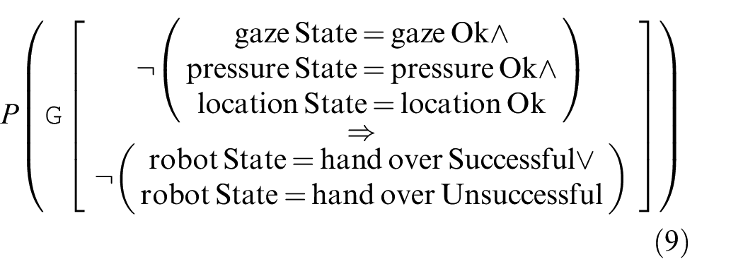
This property says that it is always the case that if the human’s gaze, pressure, and hand location are not correct, then it is not the case that the robot has attempted to hand over the object. (Handing over the object results in either the “handoverSuccessful” or “handoverUnsuccessful” states.) Verifying this property in
Requirement 3, which says that, “if the human is ready, the robot shall hand over the object,” is formalized in a similar way:
It was expected that this property would be evaluated by
Requirement 4 states that the robot always reaches a decision within a threshold of time. This is formalized as follows:
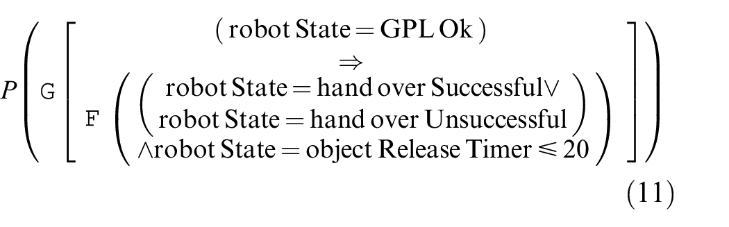
Here, the phrase “reaches a decision” was taken to mean that the robot had decided to release the object. In the model, this can result in “handoverSuccessful” if the gripper works properly or “handoverUnsuccessful” if the gripper fails. The requirement specifies that this should happen within “a threshold of time” but does not specify the amount of time. In our model, we specified that the gripper release would take 2.0 s, based on consultation with the robot’s users. Time was quantified in the model using an “objectReleaseTimer,” which is set to zero when the robot determines that the humans’ gaze, pressure, and location are acceptable. The objectReleaseTimer was set to work in 0.1 s intervals in order to provide adequate precision without increasing the size of the state space to intractable levels. Therefore, this property captures requirement 4 as it states that once the robot has found the human’s gaze, pressure, and location to be acceptable, then it will attempt to release the gripper (either successfully or unsuccessfully) within 2.0 s.
This property was verified and the probability was determined to be 0.9999999999999996, or 100.0%, allowing for floating point arithmetic precision errors in
Requirement 5 states that the robot shall always either time out, decide to release the object, or decide not to release the object. It is formalized as follows:
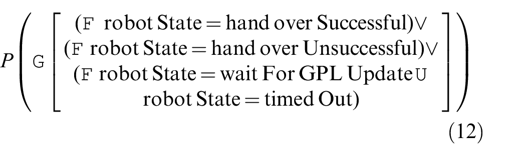
This property specifies the probability that it is always the case that the robot eventually decides to release the object (either successfully or unsuccessfully) or times out while waiting for the human’s gaze, pressure, and location to update to acceptable values. The latter case, where the robot times out, is effectively the same as the robot deciding not to hand over the object.
This property was verified, revealing a probability of 0.9979999999999996; this was expected, as the runtime error encountered in Section 5.4, which was also included in the PRISM model, has a failure rate of 0.2% or 0.002. To check that this was the case, another property was specified which says that the robot can behave as expected in the previous property, or eventually encounter a runtime error:
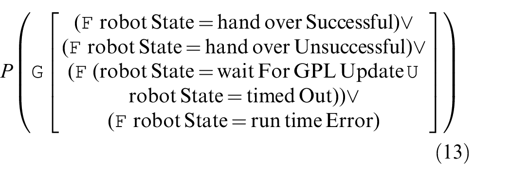
This property was verified, resulting in a probability of 0.9999999999999993, or 100.0%, allowing for precision errors.
Requirement 6 states that the robot shall not close its hand when the human is too close, requirement 7 says that the robot shall start in a restricted speed mode, and requirement 8 says that if the robot is within 10 cm of the human the robot’s hand speed is less than 250 mm/s. These properties could not be modeled, specified, or verified formally as the PRISM model of the handover scenario does not include a model of a proximity sensor, and does not allow for speeds or distances to to be set within the control system. It is possible, in principle, to re-model the scenario to include such detail. However, adding complexity to the model adds to the computational resources required to verify the model. In some cases, formal verification can become intractable. Therefore, it may be more practical for V&V of requirements 6–8 to rely more heavily on evidence gained from simulation and experiment where physical properties can be much more fine-grained.
6.4. Computational demands
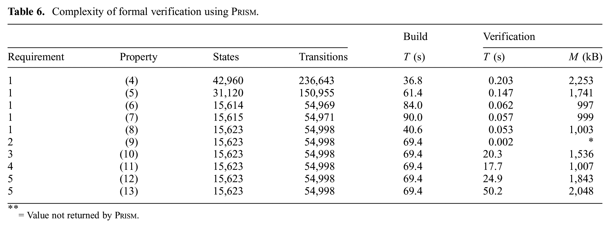
Properties (4) to (13) were verified against several different
Complexity of formal verification using
= Value not returned by
It can be seen that properties (10)–(13) took significantly longer to verify than the other properties. This is most probably the result of the use of nested temporal logic operators (e.g.,
Simulation-based testing was performed using ROS Indigo, and Gazebo v2.2.3 on a quad-core Intel® Core™ i7 laptop with 8 GB of memory running Ubuntu Linux 14.04. With all online monitors running, simulations were executed at a speed of
7. Discussion
Through the corroborative combination of a number of V&V techniques, namely formal verification, simulation-based testing, and experiments, we have determined the handover success rate (requirements 1a and 1b) with greater confidence than could be achieved by any of the V&V techniques in isolation. Each of the different V&V techniques was used iteratively to corroborate the evidence found by the other techniques during the corroborative V&V process. Although the experiments alone would have returned a similar value for the handover success rate, achieving corroboration in model checking and in simulation gives a higher level of confidence that the experimental results are correct and that the robot system meets its requirements.
The corroborative V&V process exposed key differences between the models used in the V&V techniques, specifically the false negative and true positive rates for the gaze, pressure, and location sensors, as well as the grip failure rate. For requirements 4–6, the combination of simulation-based testing and formal verification exposed important system behaviors not observed in the experiments, i.e., requirement violations. The observed runtime error (which caused violations of requirements 4 and 5) could only be exposed through a large number of tests in simulation. The subsequent inclusion of this error in the formal model and the simulator ensured that its impact on the behavior of the system could be explored with more coverability using formal verification and simulation-based testing. Furthermore, corrected models for these two V&V techniques were obtained to balance coverability capabilities, expressivity, and realism.
Corroborative V&V has demonstrated that (i) the system satisfies requirement 1b and (ii) the more stringent version, requirement 1a, is not satisfied, to a greater degree than if the individual V&V techniques were used without corroboration. Based on the insights gained during the V&V process, several design recommendations could be made to improve the handover success rate and to satisfy other requirements. The sensing process could be made more robust to sudden changes in the human motion, or to reduce the number of handover failures due to sensing errors through mechanisms such as “debouncing” for the sensor readings. (Debouncing prevents a single event from creating more than one sensor signal.) Adjustments to the robot’s hardware or motion planning strategy might improve the gripper failure rate. A speed limit needs to be introduced when the robot is reset, to avoid dangerous unintended collisions. Also, as uncontrollable faults can be encountered during execution, we could instrument our code to perform diagnostics and fault recovery strategies.
For demonstration purposes, we focused on achieving corroboration relating to a particular set of requirements, requirements 1a and 1b. As our examination of requirements 2–8 demonstrates, corroboration on some requirements does not entail corroboration across all requirements. For requirements 1a and 1b, the end result was that all V&V techniques agreed on the success rate of handover within a range of
Therefore, in practice, corroboration between V&V techniques might not be possible. At this point, we might assess whether our V&V techniques are up to the job. Perhaps we should use an automated theorem prover rather than a model checker? Or perhaps a two-dimensional physical simulation would work better than a three-dimensional one? Perhaps we could create the simulation using a different programming language or use a more powerful computer? The list goes on.
We might also decide that exact corroboration is not necessary if all the V&V techniques are within an acceptable range. For example, we might have three different pieces of evidence, each generated by a different V&V technique:
E
E
E
Clearly all three pieces of evidence are not in agreement with the others. However, the lowest value for system reliability given is 92%, which means that all three V&V techniques agree on the following statement: “System reliability is 92% or greater.” Note that this statement is implicit in evidence E
There may be other reasons, beyond those discussed in this section, why we cannot reach corroboration between V&V techniques, and there may be other ways to remedy this beyond range-based statements like the one described. It is intended that the suggestions given here may provide direction for managing corroborative V&V in practical applications, as well as acknowledging that corroborative V&V is not perfect. Rather, it is an approach to using V&V techniques in conjunction with one another to provide a higher degree of confidence that a system will satisfy its requirements.
As we have improved the accuracy of our assets on the basis of the results presented in this paper, we could use the same V&V techniques to further explore the HRI. For example, it is possible to explore human behaviors that deviate from the typical use case, and incorporate aspects of user uncertainty and variability beyond those used in this paper. A reformulation of the system and requirement models under the new conditions might be necessary, as system traits (e.g., failure rates) characterized under one set of constraints will not necessarily hold for other sets of constraints. In such cases, the V&V engineer should judge whether any prior asset modifications can be generalized to broader scenarios.
The V&V efforts toward corroboration can be helped by limiting (or biasing) the explored region of the HRI state space to seek cases in which the V&V techniques provide contradictory results. In our case study, we have employed a probabilistic formulation of the requirements that is relevant to HRI system as non-determinism may arise not only from the environment but also from the robot and the coupling between them (ROS-based robots exhibit high levels of concurrency and run on non-real-time operating systems). Hence, we can compute conditional probabilities, such as, “Given that the robot’s gripper fails, what is the probability that the robot warns the user before the object drops?” that lead to conditional evidence.
In more complex scenarios, it might become more difficult to identify appropriate modifications to achieve better agreement between assets. Modifications to system models may be informed by knowledge gained during V&V. For example, useful insights may be contributed from systematic risk analyses, such as fault tree analysis or HAZOP (hazard operability). The latter has recently been proposed for use in human–robot interactions to manage the inherent complexity and uncertainty in such systems (Guiochet et al., 2013).
Increased modeling effort is an evident limitation of corroborative V&V. However, the use of several V&V techniques brings savings to this effort. As our case study demonstrates, early use of more abstract methods allows gradual commitment of resources to more realistic and expensive techniques. Discrepancies can highlight oversights and areas of uncertainty, informing the judicious use of more expensive techniques (e.g., to characterize the uncertain grip failure rate before proceeding with user experiments in our case study).
For more comprehensive V&V efforts, coverage-driven verification (Araiza-Illan et al., 2016) may be used with corroborative V&V, pursuing coverage of the system in a systematic way in simulations or experiments. Hybrid systems methods (Julius et al., 2007; Kim et al., 2006) might also be usefully incorporated into corroborative V&V, although reducing entire HRI scenarios to manageable hybrid models is likely to be challenging.
The object handover is only an example of a huge variety of case studies available in the HRI domain. Nonetheless, it is of uttermost interest in HRI, as close-proximity manipulation tasks may be considered in a plethora of applications, such as the manufacture of white goods, cooperative handling and attachment of large sub-components of airplane structures in aerospace assemblies, or care of older people with early stage dementia by feeding them soup.
While our approach can be extended to any HRI application, in principle, an awareness of the limitations of each V&V technique is essential. For example, human behavior is notoriously difficult to analyze and assess, with open-ended and physically unconstrained interactions between humans and robots being some of the most difficult problems in HRI research. In complex and nuanced scenarios, we may wish to emphasize the use of experimentation and real-world operations over simulation and formal verification as providing core evidence for corroborative V&V. However, it is likely that many complex interactions can be broken down into simpler sub-interactions, such as object handover. In these cases, the high levels of efficiency, coverability, and precision offered by formal verification and simulation-based testing can be more readily utilized.
7.1. Use of other V&V techniques
The corroborative V&V approach can also make use of other V&V techniques, as well as their accompanying assets. For example, hardware-in-the-loop experiments allow hardware modules to be used alongside simulated hardware in order to verify the behavior of those modules (Martin and Emami, 2006). In terms of abstraction level, hardware-in-the-loop fits between simulation and experimentation, as it makes use of both. Hardware-in-the-loop experiments can verify textual requirements as well as code assertions, and the system model is a combination of the hardware modules and simulator. Therefore, we could add hardware-in-the-loop as a V&V technique within a corroborative V&V approach (see Figure 9).
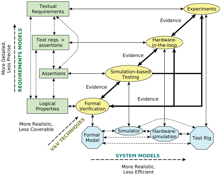
Corroborative V&V including hardware-in-the-loop.
Of course, we could also expand corroborative V&V to include operations of the robotic system once it is deployed in the “real world.” Once the system is deployed, it is being used and operated by its end-users, so naturally, its “requirement model” is the end-users’ actual requirements, rather than a model captured in natural or formal languages (see Figure 10). We could also use other V&V techniques, like coverage-driven verification (Araiza-Illan et al., 2015).
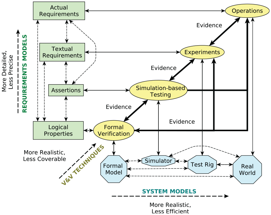
Corroborative V&V including real-world operations.
The entire corroborative V&V approach is summarized in Figure 11. A set of requirements models (shown in rectangles) is linked to system models (shown in octagons) through a set of V&V techniques. Information gained from V&V techniques can be compared with other V&V techniques, shown by bold arrows. This information can also be fed back to requirements models and system models (i.e., the V&V assets) in order to refine them to improve accuracy if the V&V techniques have shown that there is insufficient corroboration. The assets can then be refined and compared with one another, before conducting further V&V until all techniques corroborate one another. Of course, as we have shown in this paper, this is an ideal case, and full corroboration will often not be possible. However, the practice of corroborative V&V allows and encourages a systematic approach to reaching agreement between V&V approaches. In turn, this approach to V&V produces a higher quality of verification and validation than could be achieved by using the individual approaches separately.
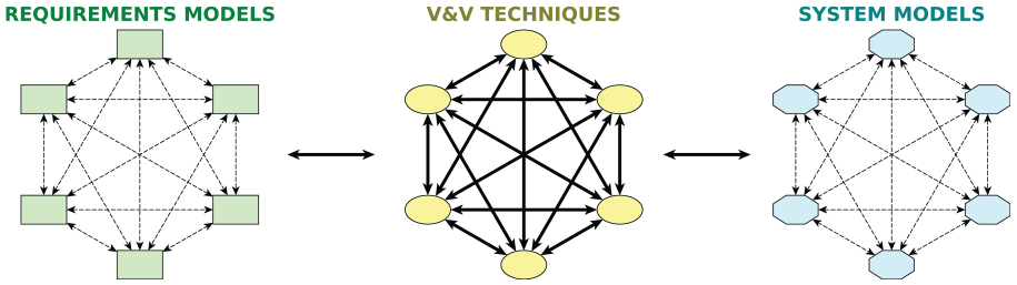
A more abstract view of corroborative V&V using several V&V techniques.
8. Comparison with other approaches
In this paper, we have described corroborative V&V: an approach to V&V of robotic systems based on combining different V&V techniques and comparing the evidence generated by them. This was motivated partly by a well-known issue: the use of a single method for V&V results in a compromise between examining the full state space of a system (in this case, of an HRI) and modeling the system in satisfactory detail.
8.1. Formal methods for V&V
Model checking (Clarke et al., 1999; Fisher, 2011), a formal method used for V&V, is exhaustive over the state space of a model but requires abstraction of the full system (e.g., the high-level control algorithms, low-level control, and mechanical behavior, and the code that runs in the robot) into a finite number of states. For this reason, formal verification can be applied to the analysis of high-level decision-making engines for safety and liveness purposes, exemplified by our previous work in HRI scenarios (Bordini et al., 2009; Dixon et al., 2014; Gainer et al., 2017;Webster et al., 2015). Reasoning and high-level control algorithms have been verified through formal verification and model checking for other kinds of autonomous robots, such as ground robots (Mitsch et al., 2017), unmanned aircraft (Webster et al., 2013), and multi-robot swarm systems (Dixon et al., 2012; Konur et al., 2012). Theorem proving, another formal method, has also been used to verify some of the control code of an autonomous robot (Walter et al., 2010) and multi-robot swarms (Behdenna et al., 2009), highlighting the same modeling challenges in terms of abstractions versus accuracy and expressivity as in model checking.
8.2. Simulation for V&V
Although formal models can be run in simulation-mode when model checking is not practical (Nielsen, 2014), dedicated simulators are preferred for robotics V&V. Unlike formal methods, simulation-based testing is not exhaustive and cannot offer proof of requirement satisfaction. However, simulators allow more detailed modeling of the physical and low-level implementation aspects (e.g., sensors or joint controllers in the actuators), and the robot’s actual control code can be executed for V&V purposes. This is because simulators do not need to be exhaustive, so computational resources can be used to model systems at a lower level of abstraction than is seen in formal verification. For example, a simulator was built in MATLAB by Kirwan et al. (2013), whereas Arnold and Alexander (2013) used the Player/Stage 2D simulator and Pinho et al. (2014) used the SimTwo simulator, in combination with the ROS robot software development framework, to test autonomous navigation control algorithms. Navigation algorithms were also validated in simulation by Sotiropoulos et al. (2017) by using MORSE, the Modular OpenRobots Simulation Engine (LAAS CNRS, 2016). In our previous work, we developed simulators in a 3D physical engine, Gazebo, containing models of the robot’s joints and continuous motion in space, along with its continuous environment containing objects and humans (Araiza-Illan et al., 2015, 2016).
In other domains, such as microelectronics, both formal methods and simulation-based testing are used, e.g., electronic design automation tools. Simulation and formal methods have been used in combination to overcome the limitations of model checking or to provide human-readable evidence of failures that can be observed at runtime. Emulating these principles, academic formal analysis tools also offer both model checking and simulation-based testing, such as UPPAAL (Nielsen, 2014), Event-B (Event-B, 2019), and the FDR4 tool (University of Oxford, 2012). Nonetheless, performing both model checking and testing over the same formal model is disadvantageous when gaining confidence in the resulting V&V evidence, as these two V&V techniques are subject to the same modeling and coding errors. This problem is highlighted by Kirwan et al. (2013), as they crafted a simulator (in MATLAB) and a formal model (in Promela for the SPIN model checker) of their robot’s software (an autonomous navigation closed-loop system) independently to overcome the limitations of simulations and model checking and gain confidence in their results. Intana et al. (2013) combined the advantages of simulation and formal verification for wireless sensor networks. Simulations in an environment called MiXiM allowed functional issues to be discovered in a high-fidelity model, whereas formal verification in Event-B was used to provide proofs of requirement satisfaction or violation to strengthen the discoveries during simulation. Intana et al. (2013) do not consider a course of action if the results from simulation contradict those from formal verification, as is done in the corroborative V&V approach presented in this paper.
Experiments in real-world scenarios are costly when compared with simulation and formal methods and cannot thoroughly explore the full state space of an HRI scenario. Simulation and experimentation can be combined through hybrids of human-in-the-loop and simulation or robot-in-the-loop and simulation, as proposed by Petters et al. (2008). However, corroborative V&V allows the use of a number of techniques, e.g., formal methods, simulation-based testing, and experiments, to verify and validate various requirements, eliminating the need to choose between examining the full state space of an HRI and modeling the HRI in satisfactory detail.
8.3. Model validation and meta-V&V
Our corroborative V&V approach draws on different forms of evidence from various V&V techniques to support a claim. In that sense, corroborative V&V can be seen as a “meta-level” approach to verification and validation, in which V&V is achieved through a comparison between the results of different V&V approaches.
The clear presentation of such arguments, e.g., by goal structuring notation (Kelly and Weaver, 2004), is an important consideration in safety-critical systems. Hawkins et al. (2011) describe the importance of separating a safety argument from its accompanying confidence argument, which justifies the sufficiency of confidence in the safety argument. Like our approach, but more limited in terms of variety of V&V techniques, the claims computed with a new variant of formal analysis, based on models of flows instead of models of states, are validated by experiments in the laboratory (Lyons et al., 2013). Lyons et al. (2013) applied the verification technique to autonomous navigation algorithms for multi-robot missions for Pioneer-3AT robots, but their validation stage only involved one robot. An approach to test robotic software through co-simulation was presented by Broenink et al. (2010), who used formal verification to find deadlocks through the FDR2 tool, while models of the robot’s software and hardware at different levels of abstraction allowed a thorough testing of the discrete and continuous interacting components. These multiple simulators run in a synchronized manner in a co-simulation. They do not consider a course of action when finding discrepancies between the formal analysis and the simulations.
In corroborative V&V, we seek agreement between different V&V techniques with respect to particular set of requirements. Discrepancies may arise as a result of inaccuracies or errors in one or more of the system models, requirements models, or tools used. In several previous works, methods have been proposed for improving the models. For example, formal models are refined iteratively if they produce a spurious property violation after model checking in counterexample-guided abstraction refinement (CEGAR) (Clarke et al., 2000). An initial detailed model is abstracted to form a simpler upper approximation for which model checking is tractable. After encountering a violation of a requirement, that model is iteratively and automatically refined to determine whether the violation is spurious (i.e., does not occur in the more detailed model). The level of detail that may be accounted for by such techniques remains limited to that which can be formally modeled. For a system’s software, this may extend to the concrete code design, but for complex cyber-physical systems, such as HRI, there will typically be important details that cannot be adequately represented. Corroborative V&V may be seen as an approach in the spirit of CEGAR, with greater dependence on human judgment to extend beyond formal modeling and accommodate system models between which absolute agreement might not be achievable.
Many approaches have been proposed to verify and validate requirement models with respect to consistency, completeness, and precision. For example, Heitmeyer (2007) developed a tool that performs formal verification (both model checking and theorem proving) as well as simulation and even code generation by integrating multiple external tools. Nonetheless, further advantages can be gained when different independently applied V&V techniques are combined to gain confidence in the results, as we propose here.
Frameworks to verify and validate models for simulation tasks with respect to accuracy and validity have been proposed (Robinson, 1997; Sargent, 2013). These models are developed by gathering real-world data, and their V&V continues throughout its simulation use. Dimensions that can be verified are: concept (aspects to be included in the model, such as variables of importance), data (e.g., accuracy, format), timing, control, and information flows, and even the code, against bugs. Techniques that can be applied for V&V include animation, comparison against other models, and testing (e.g., stress, sensitivity, and historical data comparison). Nonetheless, the authors do not prescribe a methodology with associated tools to achieve model V&V.
For ROS-based systems, the accuracy of a formal model with respect to the robot’s control code may be more rigorously examined by standardizing the formal description of common ROS components, e.g., using the “ROS graph” formalization developed by Aitken et al. (2014) to enable automated reconfiguration of ROS systems. Recently, this formalization has been adopted by Hazim et al. (2016) to apply model checking to the verification of timing properties of ROS processes. This approach shows promise for ensuring that the formal model is representative of the system’s performance. Further work is needed to demonstrate whether it can be usefully extended to capture inaccuracies in modeling the environment or the requirements, which may be more challenging to model when considering physical aspects of the system besides timing.
8.4. Automated software tools
For both requirement and system models, an approach to ensuring consistency is to generate one model from another using a trusted method. Automated tools can help in this process, such as translations from MATLAB or Simulink control models or control code into formal models for model checking (Meenakshi et al., 2006; Xie et al., 2004). Formal system models can be automatically extracted from real code (Corbett et al., 2000; Gallardo et al., 2012; Mukhopadhyay, 2015), although not many tools are compatible with Python, a popular language for prototyping robotics code. Logical properties may be automatically converted into automata (Gastin and Oddoux, 2001), which may then be encoded as a monitor in the form of a finite-state machine. Huang et al. (2014a) introduce rosmop, a tool to automatically convert logical properties into monitors for runtime verification of ROS code. Similar approaches could be adopted in combination with corroborative V&V for HRI to increase the level of confidence in the results, although errors could still propagate when transforming one model into another, e.g., inaccuracies in a logical property will propagate to a monitor.
A simulation-based testing process can be improved by using tests that not only stimulate the system but can also find faults, using so-called mutation-based test generation (Huang et al., 2014b). A system’s safety and liveness requirements model, crucial in a V&V task, can also be verified for consistency, correctness, and completeness, e.g., using a combination of formal methods, static analysis, and simulation, as in Heitmeyer (2007). If a system is to be designed and implemented from a requirements model, certified code generators (Naks et al., 2009) and code synthesis (e.g., refinement) (Ringert et al., 2014) can be employed. However, the validity of the resulting code is dependent on the accurate representation of non-software aspects of the system in the original model, which is especially challenging in the HRI domain. Furthermore, in practice, robots are commonly designed and built by different interacting teams, owing to the complexity of the applications.
In summary, various techniques exist to promote correctness in modeling and to bridge different levels of abstraction for V&V in robotics and other domains. However, none of these spans the full range of realism and coverability needed to thoroughly verify and validate an HRI system while systematically addressing the possibility for errors to be introduced at any level of abstraction. Confidence in the results of these techniques, if used in isolation, is thus limited. Our proposed approach does not prescribe specific V&V tools and techniques to be used. Automatic translation and connections between the used V&V techniques can be added to the approach, with discretion, to improve confidence or efficiency in the V&V exercise. For instance, in our demonstration, we exploit model-based test generation and the ROS–Gazebo compatibility as additional links between simulation-based testing and formal methods.
9. Conclusions
We presented corroborative V&V, a novel approach to the verification and validation of robotic assistants, to help in demonstrating their trustworthiness in the context of human–robot interactions. There are a multitude of V&V techniques, from formal methods like model checking, to various kinds of simulation, hardware-in-the-loop, experimentation, and real-world deployment. Naturally, there are trade-offs between different V&V techniques, e.g., owing to abstraction level, ease of modeling and coverability. Furthermore, it is likely that different V&V techniques may not initially agree on whether a particular system meets a particular requirement. Corroborative V&V allows us to use the different V&V techniques together, playing to their individual strengths. Where discrepancies between V&V techniques are found, corroborative V&V can be used to “iron out” these differences, working toward a situation where the majority of the V&V techniques are in agreement with respect to a particular set of requirements for a given system.
Therefore, corroborative V&V provides integral assurances on a robot’s safety and functional correctness through the combination of a number of V&V techniques. The use of these techniques provides corroboration at different degrees of coverability (i.e., the exploration of the HRI task) and HRI modeling expressivity, thus overcoming the shortfalls of each technique when applied in isolation. For example, model checking provides an exhaustive exploration of a system model, but at the cost of system detail, which is often lost in an abstract model. However, in simulation-based testing, we gain high-fidelity detail by running the real software, but we cannot test the whole state space of variables and behaviors. Also, an iterative process between the different V&V techniques can be used if the resulting evidence presents discrepancies, refining and improving the assets (i.e., system and requirement models) to represent the HRI task in a more truthful manner. This allows a greater level of confidence in the resulting evidence about the safety and functional correctness of the robot.
We demonstrated our corroborative V&V approach through a handover task, a safety-critical part of a complex cooperative manufacture scenario, for which we proposed safety and liveness requirements. We constructed formal models (probabilistic timed automata), a simulator (in the robot operating system and Gazebo), and a test rig for the HRI (in the Bristol Robotics Laboratory), as well as temporal logic properties and assertion checkers from the requirements. The V&V focus starts with a pair of requirements, requirements 1a and 1b, for which we sought corroboration between the three techniques by modifying the formal model and the simulator. We then examined a number of other requirements, finding previously unknown functional failures in the system. Our results showcase the benefits of our approach in terms of thorough exploration of the system under V&V at different levels of detail and completeness and in terms of gaining confidence in the V&V results through corroboration.
9.1. Future work
We will investigate how the translational potential of our proposed approach can be improved by more explicit evaluations of confidence. For example, Guiochet et al. (2015) summarize various qualitative and quantitative approaches to assessing confidence in V&V evidence. They present a quantitative model describing the propagation of confidence through particular argument structures. The results of our demonstration of corroborative V&V constitute an “alternative argument” structure, in that separate pieces of evidence can corroborate each other. Where one technique provides limited assurance—e.g., testing covers a limited state space of a higher-fidelity model while model checking covers the full state space of a lower-fidelity model—this may be accounted for by applying weighting factors to individual pieces of evidence provided by each technique. For probabilistic traits of a system, statistical techniques, such as the modified Wald method (Agresti and Coull, 1998), can be used to quantify the uncertainty (confidence intervals) arising from the limited number of tests feasible in simulation or experiment. However, it should be noted that such confidence intervals do not describe the accuracy of the models themselves. Hence, the implementation of quantitative models of confidence propagation will often rely on informal estimates of the confidence in individual pieces of evidence.
Finally, we intend to apply corroborative V&V to a broader collaborative manufacturing task, of which handover may be a subcomponent.
Footnotes
Appendix: Index to multimedia extensions
Archives of IJRR multimedia extensions published prior to 2014 can be found at http://www.ijrr.org, after 2014 all videos are available on the IJRR YouTube channel at http://www.youtube.com/user/ijrrmultimedia
BERT 2 handover experimental test rig
BERT 2 ROS–Gazebo simulation
Acknowledgements
The authors thank Kyriakos Georgiou for his support with data management.
Funding
The author(s) disclosed receipt of the following financial support for the research, authorship, and/or publication of this article: This work was supported by the EPSRC under the FAIR-SPACE (grant number EP/R026092/1), RAIN (grant number EP/R026084/1) and ORCA (grant number EP/R026173/1) RAI Hubs, the “Science of Sensor Systems Software” programme (grant number EP/N007565/1), the “Trustworthy Robotic Assistants” project (grant numbers EP/K006320/1, EP/K006193/1, and EP/K006223/1), and the RIVERAS project (grant number EP/J01205X/1).