
Abstract
Minimally invasive surgery (MIS) during cardiovascular interventions reduces trauma and enables the treatment of high-risk patients who were initially denied surgery. However, restricted access, reduced visibility and control of the instrument at the treatment locations limits the performance and capabilities of such interventions during MIS. Therefore, the demand for technology such as steerable sheaths or catheters that assist the clinician during the procedure is increasing. In this study, we present and evaluate a robotically actuated delivery sheath (RADS) capable of autonomously and accurately compensating for beating heart motions by using a model-predictive control (MPC) strategy. We develop kinematic models and present online ultrasound segmentation of the RADS that are integrated with the MPC strategy. As a case study, we use pre-operative ultrasound images from a patient to extract motion profiles of the aortic heart valve (AHV). This allows the MPC strategy to anticipate for AHV motions. Further, mechanical hysteresis in the steering mechanism is compensated for in order to improve tip positioning accuracy. The novel integrated system is capable of controlling the articulating tip of the RADS to assist the clinician during cardiovascular surgery. Experiments demonstrate that the RADS follows the AHV motion with a mean positioning error of 1.68 mm. The presented modelling, imaging and control framework could be adapted and applied to a range of continuum-style robots and catheters for various cardiovascular interventions.
Keywords
1. Introduction
According to the World Health Organization, cardiovascular diseases are among the leading causes of death globally (Alwan et al., 2011). Technological developments have the ability to improve and enable treatment of cardiovascular diseases (Himbert et al., 2009; Walther et al., 2009; Wong et al., 2010). Traditionally, open surgery via sternotomy is performed to gain surgical access to the heart, while a heart–lung machine provides life support. Accessibility to the heart is considered to be a major advantage during open surgery, which is at the expense of severe patient trauma. As an alternative, minimally invasive surgery (MIS) could reduce trauma and enable the treatment of high-risk patients who were initially denied surgery (Alfieri et al., 2007; Cribier et al., 2004; Himbert et al., 2009; Seeburger et al., 2010; Ye et al., 2010). However, limited access, vision and control of the instrument at the treatment locations impedes the performance of MIS. During interventions performed without a heart–lung machine, often beating heart motion compensation is desired and could potentially enable future cardiovascular interventions. Tracking of the beating heart requires the attention of the surgeon, whose accuracy deteriorates for complex repetitive motions up to 60 beats per minute (BPM) (Falk, 2002). Therefore, there is a demand for technology that assists the clinician via shared control during the procedure.
In this study, we focus on a model-predictive control (MPC) strategy that anticipates and compensates for the beating heart motion (Figure 1). The MPC strategy is used to compensate the beating heart motion by using a robotically actuated delivery sheath (RADS). Another advantage of MPC is the ability to integrate motion constraints on the instrument in order to prevent damage to sensitive tissue during the procedure. As a case study, we use transcatheter aortic valve implantation (TAVI) to demonstrate the potential of our MPC strategy. Further, applications such as ablation, valve repair surgery and mitral valve chordal replacement can potentially benefit from such an MPC strategy. TAVI can be performed via the transfemoral (TF) or transapical (TA) routes. In this case study, we focus on the TAVI-TA approach, which provides direct surgical access to the aortic and mitral heart valves (Johansson et al., 2011; Ye et al., 2010).

Model predictive control (MPC) can be used to steer the robotically actuated delivery sheath (RADS) in order to assist the clinician during cardiovascular surgery. The potential of MPC in cardiovascular surgery can be demonstrated by compensating for the aortic heart valve (AHV) motion in a representative case of transapical transcatheter aortic valve implantation. The RADS ① is inserted through the apex ② into the left ventricle ③ and oriented towards to the aortic annulus ④. The articulating tip ⑤ of the RADS can be steered inside the left ventricle under ultrasound ⑥ image guidance in two degrees of freedom by two pairs of antagonistically configured tension wires. Pre-operative ultrasound data ⑦ can be used as an input to the MPC strategy to anticipate and compensate the AHV motion during surgery.
1.1. Related work
Recent studies have demonstrated the capabilities of MIS in cardiovascular applications such as angioplasty and patent foramen ovale (Gosline et al., 2012; Jayender et al., 2008). These studies describe the use of robotic instruments in order to enable MIS. However, MIS in cardiovascular applications such as coronary artery bypass, ablation and valve surgery could significantly benefit from beating heart compensation. Active robotic stabilization at the treatment location could provide a virtually still scenario that allows the clinician to perform the primary task of the procedure as if the heart was stopped. Compensation of beating heart motions has been extensively covered in research. Studies that focused on the beating heart surface have been described (Bebek and Cavusoglu, 2007; Gangloff et al., 2006; Ginhoux et al., 2005; Nakamura et al., 2001; Ortmaier et al., 2005; Richa et al., 2010; Tuna et al., 2013). These studies cover various predictive strategies by filtering and control to anticipate the beating heart motions. Ortmaier et al. (2005) reported significant correlations between beating heart motions and electrocardiogram (ECG) signals, which were utilized for synchronization by Bebek and Cavusoglu (2007). The majority of these studies used predictive strategies to improve accuracy and to anticipate for occlusions in endoscopic camera images, while this study focuses on ultrasound-guided repair surgery in the beating heart.
Cardiovascular procedures such as ablation and valve-implantation or -repair surgery are often assisted by two-dimensional (2D) or three-dimensional (3D) ultrasound, which are used to evaluate cardiac functionalities (e.g. valve closing) (Walther et al., 2009). The presence of ultrasound imaging during the procedure provides the potential for online soft tissue and instrument tracking. Yuen et al. (2008) evaluated predictive filtering to enable ultrasound-guided robotic tracking of cardiac motions for potential use in ablation. A study by Kesner and Howe (2014) demonstrated capabilities of applying a constant force against a moving target by using ultrasound image feedback and force sensing. Whereas Bowthorpe et al. (2014) focused on predictive control using an ultrasound-guided tele-operated robot to anticipate for cardiac motions. All of these methods describe one dimensional motion compensation, which is along the lateral axis of the instrument. However, existing applications in valve implantation and repair surgery such as mitraclip placement could benefit from motion compensation in two or more degrees of freedom (DOFs) (Tamburino et al., 2010; Wong et al., 2010; Ye et al., 2010). Further, beating heart motion compensation in two or more DOFs could potentially enable future applications in minimally invasive cardiovascular surgery. In this study, we cover an integrated system capable of autonomously and accurately compensating for beating heart motions in two dimensions by using an MPC strategy. Further, our MPC strategy guided by ultrasound imaging considers active constraint handling in order to avoid damage to sensitive tissue. Major aspects in MPC of the integrated system are kinematic modelling of continuum-style robots and feedback on its pose.
Kinematic modelling is used to describe the RADS shape and articulating tip motion. Modelling of continuum-style robots have been investigated by several groups (Bardou et al., 2010; Camarillo et al., 2008; Ding et al., 2010; Dupont et al., 2010; Reiter et al., 2012; Rone and Ben-Tzvi, 2014; Webster and Jones, 2010). Various continuum-style robotic instruments with potential in cardiovascular applications have been described in literature. These devices can be mainly classified into tendon-driven robots and pre-bent concentric tubes. We describe the kinematics of the tendon-driven constant-curvature RADS using both robot-specific and -independent submappings (Webster and Jones, 2010). The kinematics presented in this study considers a rigid link which is attached to the flexible segment of the RADS. However, modelling mismatches and disturbances acting on the system affect the tip positioning performance of continuum-style robots.
Tracking of continuum-style robots plays an important role in order to reduce control tracking errors caused by modelling mismatches and external disturbances. In TAVI, the clinician is often assisted by 2D and 3D transoesophageal or transthoracic echocardiography (Walther et al., 2009). 2D ultrasound has been used for 2D and 3D tracking of flexible instruments by several groups (Hong et al., 2004; Neshat and Patel, 2008; Neubach and Shoham, 2010; Vrooijink et al., 2013, 2014). 3D ultrasound-based tracking of cardiac catheters (some equipped with markers) have also been described in the literature (Koolwal et al., 2010; Nadeau et al., 2015; Novotny et al., 2007; Stoll et al., 2012). In this study, we integrate an online and a robust tracking algorithm that uses 2D ultrasound images of the RADS.
1.2. Contributions
In this study, we demonstrate an integrated system that assists the clinician by compensating for beating heart motions, which could be used in existing and potential future cardiovascular interventions. By active stabilization of the instrument in the beating heart, a virtually still treatment location could be provided. This allows the clinician to perform the procedure as if the heart was stopped. Such a system requires instrument modelling and tracking, which is integrated in a control strategy capable of anticipating for beating heart motions. In this study, we incorporate the forward, inverse and differential kinematic models of the RADS, which considers a rigid link or a tool attached to the flexible tip segment. Subsequently, we integrate a robust 2D ultrasound image segmentation algorithm capable of online evaluation of the RADS tip position. Furthermore, we provide the control objective and corresponding MPC strategy, which considers kinematic modelling and ultrasound feedback. The MPC strategy anticipates for beating heart motions by incorporating models based on pre-operative patient data. In addition to the aforementioned contributions, the MPC strategy considers active constraint handling in order to prevent damage to sensitive tissue. To the best of the authors’ knowledge, we are the first to present an ultrasound-guided MPC strategy capable of compensation for beating heart motions in 2D using a RADS. As a case study, we focus on TAVI-TA by integrating an aortic heart valve (AHV) model in the MPC strategy, which is based on pre-operative 2D ultrasound patient images that describes the AHV motion during the cardiac cycle. The presented strategy for beating heart compensation could be applicable to a wide variety of existing and potential future cardiovascular interventions. Further, we improved the RADS tip positioning accuracy by compensating for instrument hysteresis. Three experimental scenarios using a water container setup demonstrate MPC of the novel integrated system that autonomously and accurately compensates for AHV motions.
2. Methods
This section presents techniques to enable tracking and MPC-based steering of the RADS. Details on the design of the RADS are provided by Vrooijink et al. (2014). We summarize the forward, inverse and differential kinematics which are used in MPC. Furthermore, we describe the 2D ultrasound segmentation method of the RADS used as feedback for MPC. The MPC strategy includes modelling of the heart valve motion based on pre-operative 2D ultrasound data. By combining the kinematic modelling and segmentation of the RADS with MPC, the system is able to anticipate the beating heart motion. Note, in the derivations presented, for notational simplicity, we leave out the discrete time variable denoted by k (except where needed for clarity). Further, the nomenclature describing the variables used in this study is provided in Appendix B.
2.1. Instrument modelling
2.1.1. Forward kinematics
The design and integration of the tendon-driven RADS used in this study is shown in Figure 2. Two pairs of antagonistically configured tension wires are used to actuate the articulating tip of the RADS in two DOFs. Each pair of wires is actuated by a single pulley and controls tip movement in a single DOF (Figure 2). The four-wire design allows for tip movement in two DOFs by using two actuators instead of the three that are required in an instrument with three wires. A kinematic model of the tendon-driven continuum-style robot can be described by a robot-specific and a robot-independent submapping (Webster and Jones, 2010). The robot-specific mapping relates the actuator space to the configuration space. The actuator space is given by the angles of the pulleys (
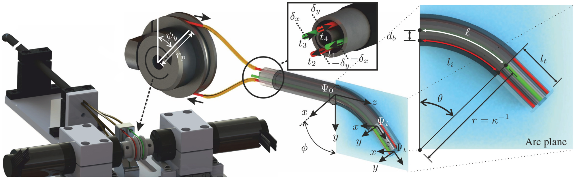
An overview of the robotically actuated delivery sheath (RADS). The articulating tip of the RADS is actuated in two degrees of freedom by two pairs (red and green) of antagonistic-configured tension wires driven by a two pulleys with radii (
In order to evaluate the arc parameters of the configuration space, the relation between tendon manipulation at the base and the resulting arc needs to be described. In the derivation presented, we denote for notational simplicity:

where
Given the tendon configuration as illustrated in Figure 2, we can formulate the individual tendon angles by

The antagonistic configuration allows for pairing of the tendons described by

while the curvature is evaluated as
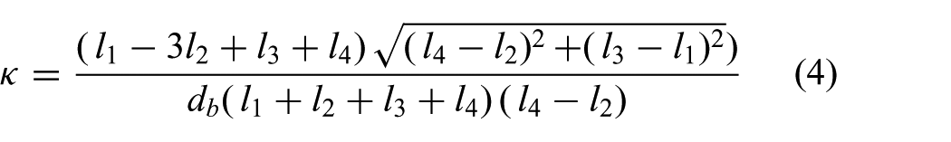
Note that the arc parameters (

and

respectively. Hence, we obtain the arc parameters (
The robot-independent mapping is given by the homogeneous transformation matrix (
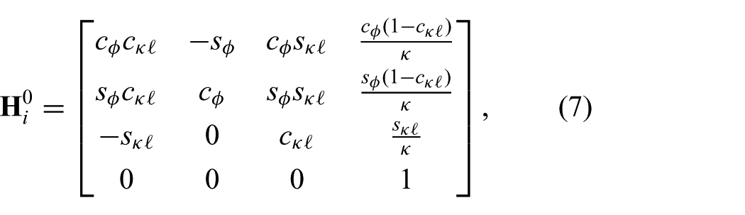
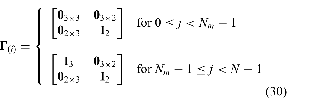
which describes the mapping between the intermediate frame (

and

which are defined for
In order to describe the articulating tip frame (
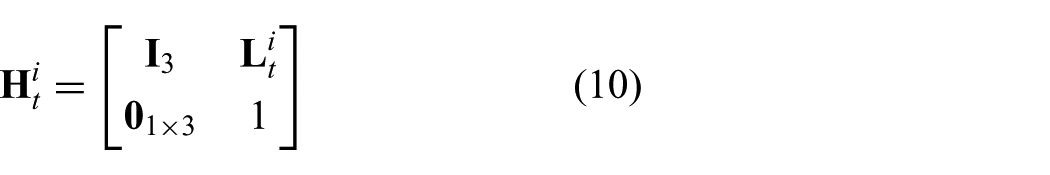
where
2.1.2. Inverse kinematics
The inverse kinematics is used to express the pulley angles (

Subsequently, we use the forward kinematics presented in (7) and (10) to derive an expression for the reference tip position (
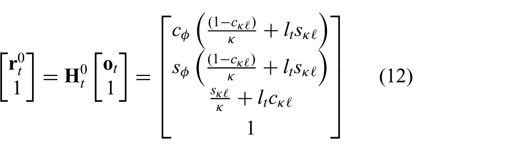
where
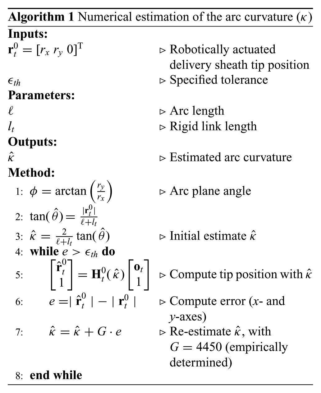
We first estimate an initial value for the arc curvature (
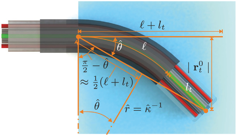
Overview of the geometric relations used to estimate an initial value for the arc curvature (
2.1.3. Differential kinematics
Differential kinematics is used to relate the change in instrument arc parameters (

where
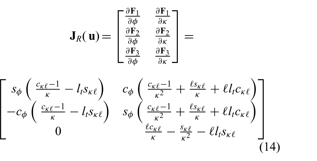
uses the forward kinematics described in (12) to analytically derive the differential kinematics. Note, that similar to (7), discontinuities for
2.2. Ultrasound image segmentation
This section elaborates on the segmentation techniques applied to evaluate the RADS centroid location in 2D ultrasound images. In order to view the tip of the RADS in ultrasound images, we insert the instrument in a container and use water as an acoustic transport medium. A radial cross-sectional view of the RADS is obtained by orientating the 2D ultrasound image plane perpendicular to the shaft of the instrument (Figure 4). The RADS tip is positioned in the ultrasound image plane by axial positioning, which is described in details in Section 2.3.4. Note, that by axial positioning, the segmented RADS tip frame in ultrasound images (frame (
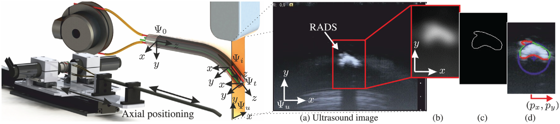
Ultrasound image segmentation to evaluate the centroid location (
A representative ultrasound image of the instrument tip is shown in Figure 4(a). We observe a semi-circular shape that describes the reflecting surface of the RADS. By evaluation of the pre-operative ultrasound data (Figure 6), we did not observe identical semi-circular shapes that represented anatomical structures. Therefore, we use segmentation techniques based on the circular shape parameters to localize the tip of the RADS in ultrasound images. Further, the acoustic impedance difference between RADS materials and cardiac tissue is considered to be significantly large, which enhances the visibility of the instrument (Aldrich, 2007; Vrooijink et al., 2014). This would enable instrument detection when interaction with cardiac tissue is considered.
Preprocessing is performed to enhance the visibility of the RADS in ultrasound images. In order to reduce speckle and to smoothen edges in the ultrasound image, a 2D Gaussian kernel is applied, as depicted in Figure 4(b). The contrast between instrument and the environment in ultrasound images is sufficient for edge detection. Hence, we use a Canny edge detector with hysteresis thresholding to obtain an edge map of the ultrasound image as shown in Figure 4(c) (Forsyth and Ponce, 2002). Hysteretic thresholding reduces the detection of irrelevant edges, that do not describe the semi-circular surface of the RADS. However, irrelevant edges, often introduced by surface deformations caused by artifacts and bending of the instrument may still exist. Hence, the centroid location is evaluated using a random sample consensus (RANSAC) strategy (Algorithm 2). RANSAC is robust to irrelevant edges that do not fit the parametric description of the semi-circular model representing the RADS (Forsyth and Ponce, 2002).
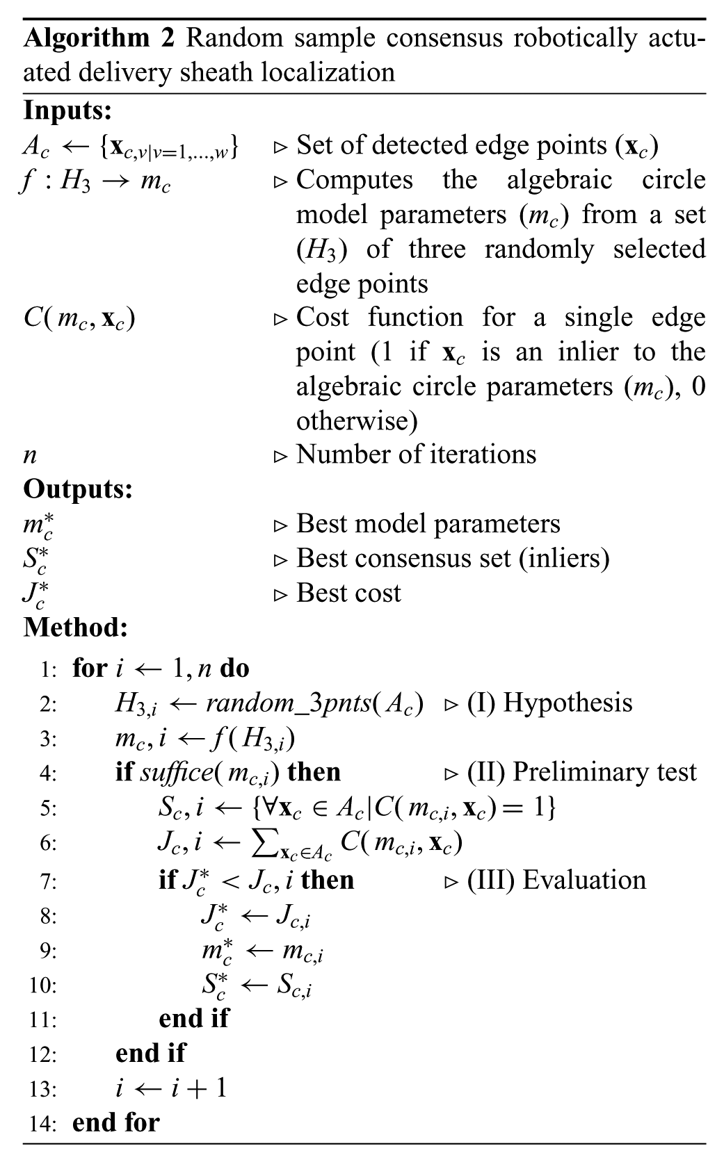
The evaluated set (
The performance of the RANSAC algorithm is evaluated and validated experimentally using a sequence of 600 ultrasound images. Experiments show that the localization error of the RADS decreases if the number (n) of iterations of the RANSAC algorithm are increased as depicted in Figure 5(b). In order to minimize computational costs and considering the ultrasound imaging resolution of approximately 0.12 mm per pixel, the number of RANSAC iterations should be limited to approximately 800, which is depicted green in Figure 4. Further, we compare the results of RADS segmentation for varying RANSAC iterations using manual segmentation as a ground truth (Figure 5(a)). The results show, that by increasing the RANSAC iterations, the segmentation error remains approximately constant (0.4 mm). Since there is no reason to believe that an increase in RANSAC iterations would deteriorate segmentation accuracy, we estimate that the insignificant increased error in Figure 5(a), could be attributed to imperfections in manual segmentations.
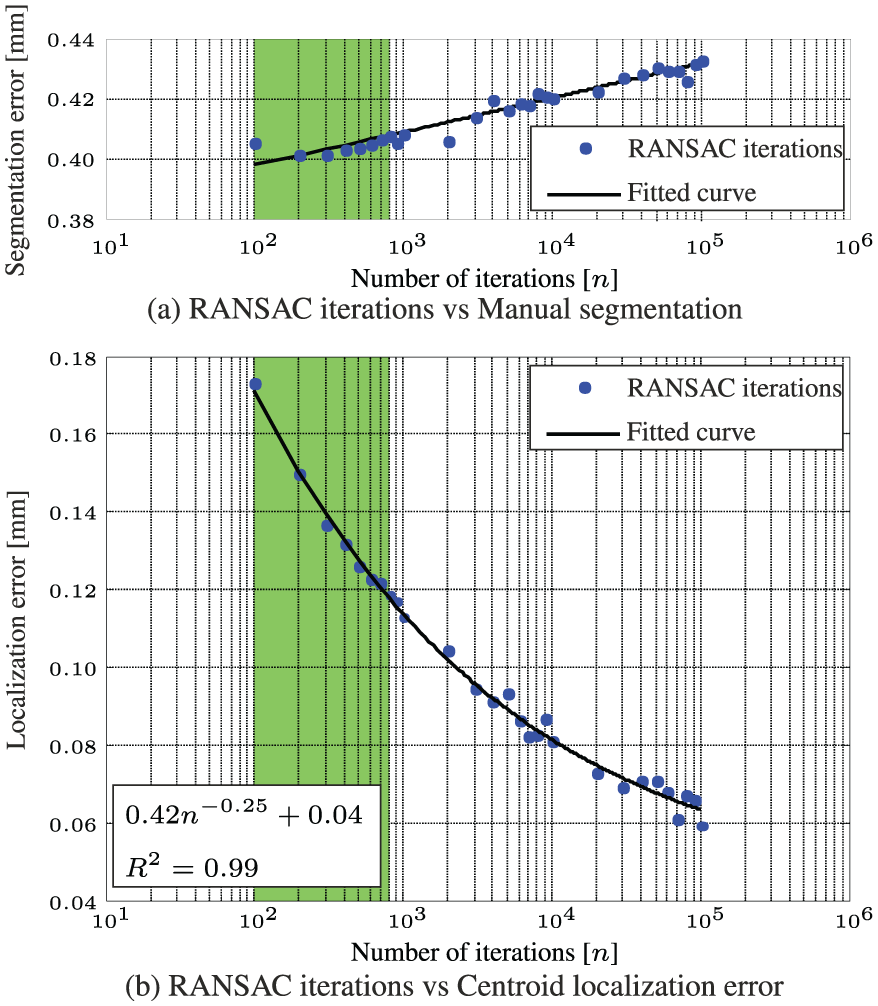
Experimental evaluation and validation of image segmentation using a sequence of 600 ultrasound images. (a) Compares the performance between varying random sample consensus (RANSAC) iterations using a ground truth obtained by manual segmentation. (b) Describes the relation between the number of iterations and the localization error using a ground truth obtained after
The presented ultrasound segmentation method is used in our closed-loop control strategy to improve the performance. Note, that the presented 2D segmentation method can be expanded to 3D ultrasound imaging by parallel evaluation of slices along the instrument shaft.
2.3. Model predictive control
In this section we present the MPC architecture used to control the RADS in closed loop. The objective of the MPC architecture is to anticipate the AHV motion based on a model. This allows the clinician to focus on the primary task of the procedure, while compensation for AHV motions is provided. In order to develop an AHV model, we use the pre-operative 2D ultrasound images that describe the AHV motion of a human during the cardiac cycle. Further, we integrate forward, inverse and differential kinematics described in Section 2.1 to determine instrument motion. The 2D ultrasound segmentation presented in Section 2.2 is used to provide instrument feedback for control.
2.3.1. Model description
The continuous time representation of the model used in the MPC strategy incorporates the differential kinematics described in (13). A cascade configuration is used according to


where

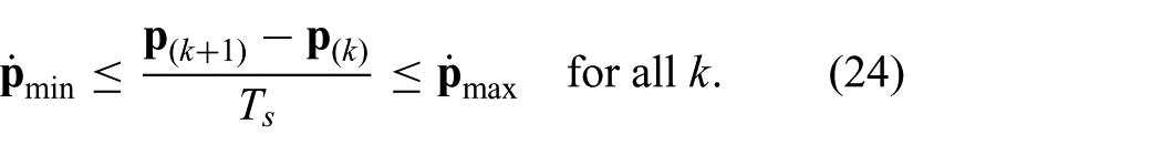
where the instrument tip position is restricted. The instrument tip position is limited in order to prevent damage to the instrument arc section. Further, by adding restricted regions for the instrument tip position, damage to sensitive tissue can be avoided. In order to preserve dominant features required for ultrasound image segmentation, we add an additional inequality constraint. The constraint is used to limit the instrument tip velocity in x- and y-directions of frame (

The discrete time model integrated within the MPC strategy can be obtained by using forward Euler discretization of the continuous time model according to


where we substitute

and
Note, that the constraints stacked into a vector can be evaluated component-wise. The presented discrete time model is integrated within MPC strategy to optimize the control objective.
2.3.2. Control objective
The main MPC objective is to anticipate the AHV motion, while considering a desired reference input. In order to capture these requirements, we can formulate a reference tracking objective according to

where
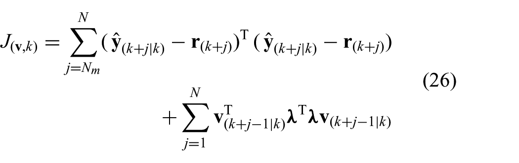
where

which evaluates the control action (

we obtain the standard form used in MPC, where

describes the reference tracking error and control action, while
is a diagonal selection matrix (
2.3.3. AHV modelling
Modelling is used to anticipate the AHV motion in MPC. As a case study, we observe the motion of the AHV annulus during the human cardiac cycle. We use pre-operative 2D transoesophageal echocardiogram (TEE) to obtain the motion profile of a human AHV annulus (Figure 6). The motion profile obtained from 2D ultrasound images is used to demonstrate compensation of the AHV motion. In this study, we assume a constant shape of the aortic annulus. Hence, we obtain the centre position of the aortic annulus by manual segmentation (Figure 6).
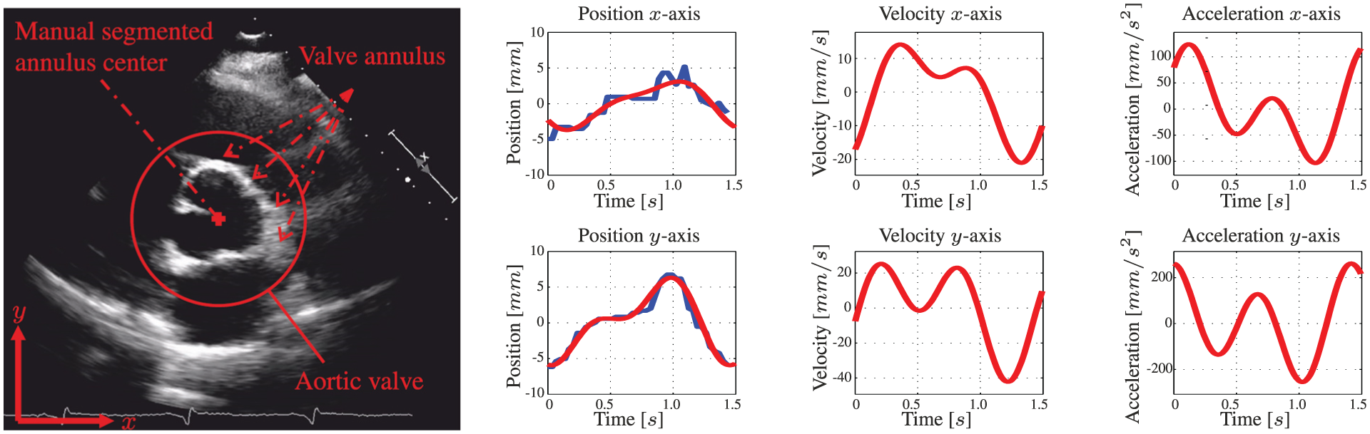
A pre-operative two-dimensional transoesophageal echocardiogram (TEE) of the aortic heart valve (AHV) annular plane. The centre location of the aortic heart valve annulus is manually segmented for multiple cardiac cycles. The human evaluated annulus centre positions are used for fitting a motion model. The blue line demonstrates the manually segmented annulus position during the cardiac cycle. The corresponding red line describes the position of the fitted model. Further, the velocities and accelerations of the AHV models are provided.
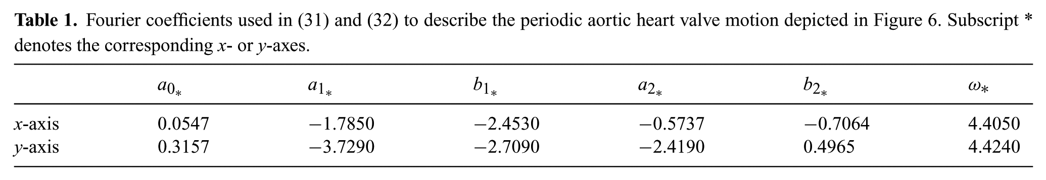
The manual segmented aortic annulus position during the cardiac cycle is used to derive a model capable of describing the periodic motion. A two-term Fourier series according to

and
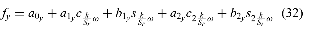
is used to describe the periodic aortic annulus motion, where k describes discrete time,
Fourier coefficients used in (31) and (32) to describe the periodic aortic heart valve motion depicted in Figure 6. Subscript * denotes the corresponding x- or y-axes.
2.3.4. Controller design
The MPC strategy used to control the articulating tip of the RADS is presented in Figure 7. The control variable (
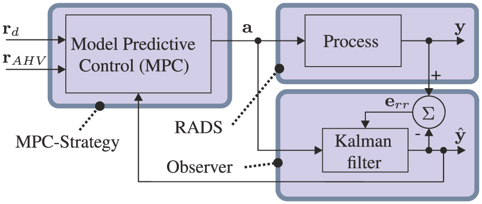
Model-predictive control (MPC) strategy is used to steer the robotically actuated delivery sheath (RADS). The referenced tip position by the clinician is denoted by
In order to describe the MPC strategy, we formulate a constrained standard predictive control problem (CSPCP), which uses a multiple-input and a multiple-output (MIMO) state-space representation of the system (Kinnaert, 1989; van den Boom and Stoorvogel, 2012). We can write the CSPCP using a MIMO model of the RADS in state-space realization according to the following:


where we use the model described in (20) to (22). The state is given by
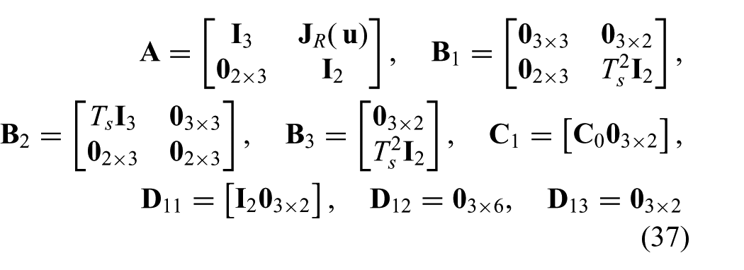
where we use the state (

In this study, we do not model external disturbances, hence we denote
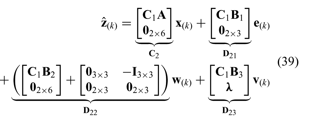
where we use the zero mean white noise estimate (
The constraints presented in (23) and (24) can be combined and described by two one-sided constraint signals (
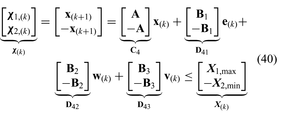
where

where
The CSPCP is used to formulate a model based on the concept of prediction, which is described in Appendix C. The prediction model is used to solve for the optimal control vector (
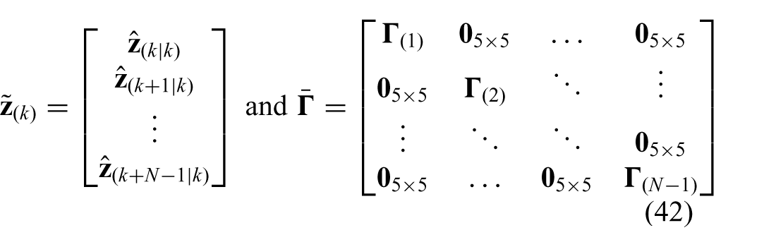
respectively, which can be used to rewrite the cost-function presented in (28) according to

The predicted cost signal (

where matrices

where the control action is assumed to be zero after control horizon (

where the equality constraint prediction vector is given by
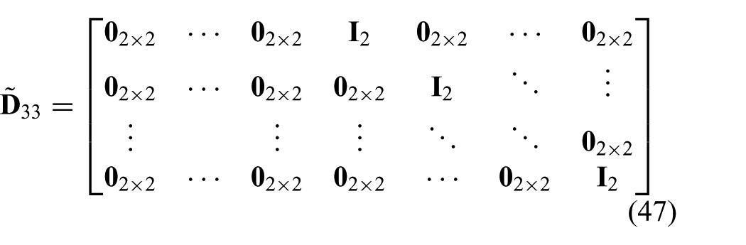
Further, a prediction vector (

which also completes the prediction model.
By minimizing the following cost function
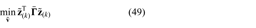
subject to constraints described in (46) and (48), we can solve for the optimal control vector (
2.3.5. Hysteresis compensation
Before the optimal solution is implemented, we compensate for hysteresis in the system. Hysteresis caused by backlash often occurs in cable-driven instruments such as endoscopes and catheters (Reilink et al., 2013). Hysteresis can be described by a positive or negative contact mode and a free mode. In contact mode, kinematics describes the relation between pulley angles (

where
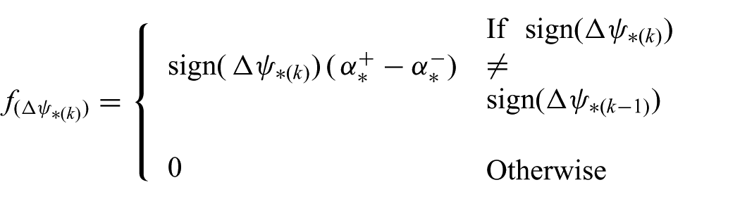
is the function that represents the compensation term. In order to limit chatter, we only apply the compensation term if the velocity changes direction and exceeds a threshold. Compensation is provided by hysteretic parameters (
3. Experiments
In this section, we present experiments performed to evaluate the MPC strategy. First, we describe the components and layout of the experimental setup used to steer the RADS. Subsequently, a pre-operative AHV model is presented and integrated with the MPC strategy. This is followed by the experimental plan and results that demonstrate the capabilities of the MPC strategy.
3.1. Experimental setup and materials
The experimental setup used to evaluate the performance of the MPC is shown in Figure 8. The RADS used in our experiments is based on a cable-ring structure surrounded by a hinged tube (DEAM Corporation, Amsterdam, The Netherlands) (Breedveld, 2010). Two pairs of antagonistically configured tension wires facilitate articulating tip movement of the RADS in two DOFs (Vrooijink et al., 2014). The tension wires of the RADS are driven by an ECMax22 motor with a GP32/22 gearhead (Maxon Motor, Sachseln, Switzerland). Further, an LX30 translational stage (Misumi Group Inc., Tokyo, Japan) is used to translate the RADS along the longitudinal axis in order to compensate for the tip motion in the out-of-image-plane direction. The maximum velocity and acceleration along the longitudinal axis are 230 mm/s and 2800 mm/s2, respectively. All motors are actuated by an Elmo Whistle 2.5/60 motor controller (Elmo Motion Control Ltd, Petach-Tikva, Israel). The RADS is inserted in a container filled with water in order to enable ultrasound-based tip tracking. A Siemens 18L6 transducer operating with a frequency of 16 MHz, a power level of −4 dB and a scanning depth of 4 cm on a Siemens Acuson S2000 ultrasound system (Siemens AG, Erlangen, Germany) is positioned at the tip of the RADS (in the container) to obtain ultrasound images as feedback. Note, that without any modifications to ultrasound image segmentation, the transthoracic echocardiography approach used in this study could be replaced by TEE. The ultrasound images are transferred via S-video output (in-plane resolution of approximately 0.12 mm per pixel) to a computer (2.80 GHz Intel i7, 8 GB internal memory and 64-bit Windows 7) with a frame rate of 25 frames per second. Further, this computer is used to implement and execute in C++ the MPC strategy which provides control signals to the motors and electronics. The MPC strategy uses a sampling time (
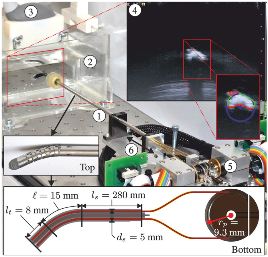
The experimental setup used to control the robotically actuated delivery sheath (RADS) using a model-predictive control strategy. ① RADS. ② Container filled with water in which the RADS is inserted. ③ Ultrasound transducer. ④ Ultrasound image with a radial cross-sectional view of the RADS. ⑤ Motors and corresponding electronics used to control the articulating tip of the RADS. ⑥ Translation along the longitudinal axis of the RADS in order to position the tip in the two-dimensional ultrasound image plane. The top inset shows the flexible segment (articulating tip) of the RADS, which uses a hinged tube construction. The bottom inset depicts a longitudinal cross-section with dimensions of the RADS. An antagonistic configuration of a pair of tension wires (red) is actuated by a pulley-driven system. Each pair of tension wires (total of two pairs) is guided through the flexible shaft and through two incompressible brass tubes (yellow) to actuate a single degree of freedom of the articulating tip.
3.2. Experimental scenarios
A series of experiments have been conducted in order to evaluate the tracking accuracy of the MPC strategy in an integrated system using a reference signal described in (25). In previous research, a model-based approach was used to steer the RADS along a circular path using 2D ultrasound images as feedback (Vrooijink et al., 2014). The results of these experiments showed, while moving at 2 mm/s, mean positioning errors of approximately 2 mm along the x- and y-axes. In this study, we aim to improve these results and provide novel functionalities such as compensation for beating heart motions. Hence, we evaluate the performance using multiple scenarios such as tracking circular paths and AHV motions.
3.2.1. Circular path
The first set of experiments is performed in order to evaluate steering of the RADS along circular paths using the MPC strategy. Note, that no heart valve motion modelling is considered (
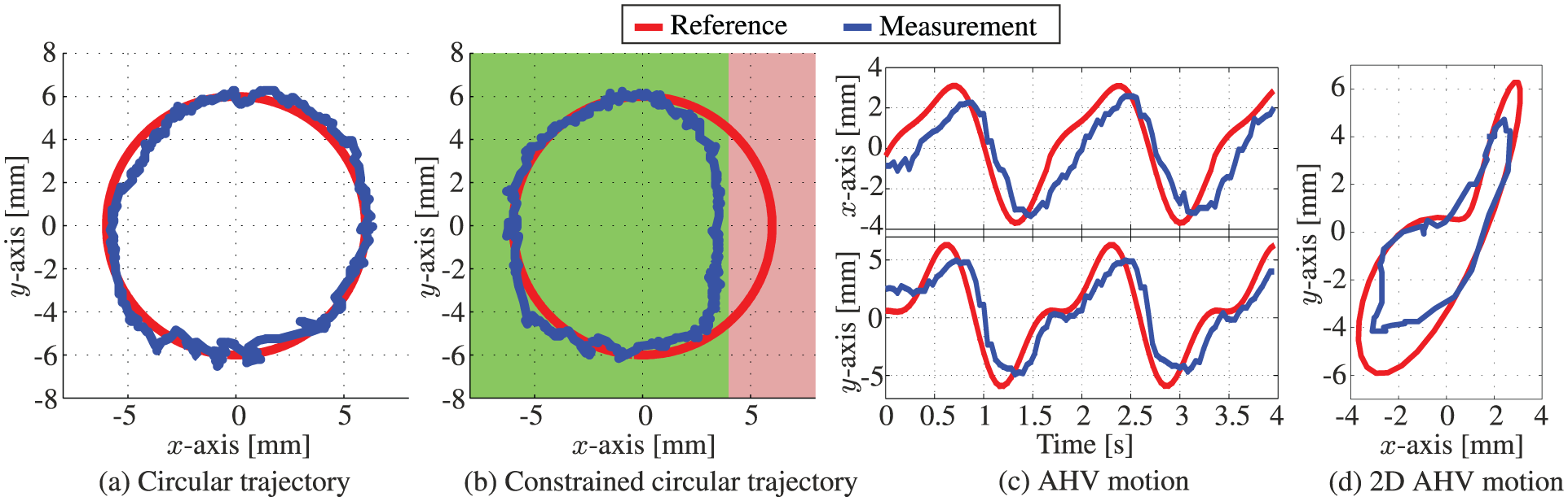
Representative experimental model-predictive control results of the articulating tip of the robotically actuated delivery sheath during tracking of (a) circular reference path (
3.2.2. Aortic heart valve motion tracking
The second set of experiments is used to evaluate the novel designed MPC strategy to steer the RADS with a priori knowledge on the AHV motion. Although, other medical applications such as mitral valve surgery could potentially benefit from the integrated system, we demonstrate the capabilities of the MPC strategy by tracking AHV motions in the annular plane. The beating heart motions have been obtained by analyzing the pre-operative 2D ultrasound images as depicted in Figure 6. We evaluate the performance of the MPC with a priori knowledge of the AHV motion described by tracking reference (
3.3. Experimental results
The results of the experimental scenarios are reported in Table 2, while a single representative of each experiment can be found in Figure 9. In order to evaluate the tip tracking accuracy of the RADS, the experiments were repeated 12 times for circular trajectories and 30 times for AHV motions. The mean absolute errors (MAE) in the tracked tip position (
Experimental results of the robotically actuated delivery sheath tip tracking for circular paths and aortic heart valve motions using the model-predictive control. The mean absolute distance error (
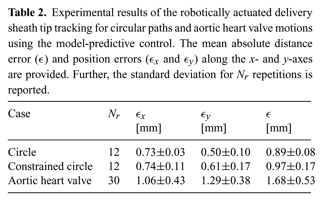
Experiments showed tracking of a circular trajectory with MAE of 0.73 and 0.50 mm in the x- and y-axes, respectively. The observed mean absolute distance error is 0.89 mm. A slightly higher error is observed in the x-axis compared to the y-axis. This could be attributed to the difference in mechanical properties such as friction and backlash of the two uncoupled pulley systems (each control a single DOF). Nonetheless, the results show a significant improvement in tracking performance compared to the mean positioning errors of approximately 2 mm along the x- and y-axes demonstrated in previous work (Vrooijink et al., 2014). Further, in the experiments that demonstrate the circular trajectory in which the instrument motion is limited, we observe a MAE of 0.74 and 0.61 mm in the x- and y-axes, respectively. The corresponding mean absolute distance error is 0.97 mm. The observed error correspond to the results of a circular trajectory without instrument limitations. Hence, we demonstrate that the MPC strategy is capable of avoiding areas that could potentially be sensitive tissue without degrading performance. By tracking AHV motions, we observe a MAE of 1.06 and 1.29 mm in the x- and y-axes, respectively. The observed mean absolute distance error is 1.68 mm. A higher error is observed in tracking AHV motions compared with circular trajectories. This could be explained by the fast moving AHV motions that impedes the accuracy of tracking. Further, we observe a decrease in tracking accuracy along the y-axis for AHV motions. The decrease in tracking accuracy could be explained by the instrument velocity which is limited to 20 mm/s in MPC in order to enable RADS detection in ultrasound images. The MPC strategy considers both the tip velocity limitation and AHV motion in order to optimize tracking accuracy.
Further, the ultrasound measurement delay introduced in the feedback signal of the MPC strategy is among the main contributor to the tracking error. This measurement delay is considered to be the combined result of pre-processing within the ultrasound system, transferring images to the computer using a capturing device and instrument segmentation. However, it cannot be ruled out that tracking accuracy is affected by (non-)linear friction, tendon elongation or crosstalk between the two tendon pairs (i.e. controlling one tendon pair influences the other tendon pair). Note, that we evaluate our system using pre-operative patient data which leads to simplifications with respect to heart-rate variability. However, these simplifications could potentially be eliminated by administering medicine that reduce the heart rate and apply over-pacing to effectively control the patient’s heart rate in a predictable manner. This improves the ability to anticipate the AHV motion. Nonetheless, our method demonstrates tracking of AHV motions based on pre-operative ultrasound patient data. This indicates that our system, with further development, could provide cardiac motion compensation to a wide class of cardiovascular applications performed without a heart–lung machine.
4. Conclusions and future work
In this study, we present and evaluate a novel RADS capable of autonomously and accurately compensating for AHV motions by using an MPC strategy. We develop and incorporate kinematic models of the RADS within the MPC strategy. In order to accurately evaluate the RADS tip position, we use a clinically available 2D ultrasound transducer which is orientated perpendicular to the tip of the RADS. An online segmentation algorithm is developed in order to provide feedback of the RADS tip position for the MPC strategy. Pre-operative ultrasound images of a patient are used to evaluate the AHV motion. Further, mechanical hysteresis is addressed by a compensation algorithm in order to improve the tip positioning accuracy. The novel integrated system is capable of controlling the articulating tip of the RADS in order to compensate for AHV motions. In experiments, we demonstrate evidence that the RADS tracks the AHV motions with a mean absolute distance error for AHV motions of 1.68 mm. Hence, we potentially improve and enable new applications in cardiovascular surgery performed without a heart–lung machine.
In future work, we intend to address accuracy problems introduced by measurement delay and instrument friction. Electro-magnetic instrument tip tracking will be integrated in order to reduce feedback delay and to improve robustness in control. The prototype device used in this study will be replaced by a flexible steerable catheter in order to enable applications in ablation, aortic and mitral valve surgery. Further, we plan to combine instrument and intra-operative AHV motion segmentation of 2D and 3D ultrasound images in order to improve the tracking performance in a clinically relevant scenario. We continuously aim to improve the robustness and accuracy of the integrated system. Nonetheless, the presented framework for modelling, imaging and control is applicable to a range of continuum-style robots and catheters. Our current study evaluates compensation of AHV motions using an MPC strategy. Hence, we have demonstrated the feasibility and potential for steerable catheters to compensate for cardiac motions in cardiovascular interventions such as aortic and mitral valve surgery.
Footnotes
Appendix A: Index to Multimedia Extension
Archives of IJRR multimedia extensions published prior to 2014 can be found at http://www.ijrr.org, after 2014 all videos are available on the IJRR YouTube channel at http://www.youtube.com/user/ijrrmultimedia
This video demonstrates some representative results of tracking circular paths and aortic heart valve motions using model-predictive control.
Appendix B: Nomenclature
| k | Discrete time variable | [-] |
| Pulley angle, where | [rad] | |
| Tendon displacement, where | [m] | |
| Arc curvature | [ ] | |
| r | Arc radius | [m] |
| Arc plane angle | [rad] | |
| Arc length | [m] | |
| Arc bend angle | [rad] | |
| Rigid link length | [m] | |
| Pulley radius | [m] | |
| Tension wires, where | [–] | |
| Tendon lengths, where | [m] | |
| Individual tendon angle, where | [m] | |
| Distance between backbone and tendons | [m] | |
| Coordinate system, where | [–] | |
| Homogeneous transformation matrix expressing the intermediate frame in the reference frame ( ) | [–] | |
| Homogeneous transformation matrix expressing the tip frame in the intermediate frame ( ) | [–] | |
| Homogeneous transformation matrix expressing the tip frame in the reference frame ( ) | [–] | |
| Rigid link section by a translation along the z-axis of the intermediate frame ( ) | [–] | |
| , | Referenced tip position expressed in the reference frame ( , ) | [–] |
| Referenced tip position, where | [m] | |
| Origin of the articulating tip frame ( ) | [–] | |
| , | Tip position expressed in the reference frame ( , ) | [–] |
| Tip position, where | [m] | |
| Arc parameters, | [–] | |
| G | Rate of convergence feedback gain | [–] |
| e | Estimation error | [m] |
| Error tolerance | [m] | |
| Set of detected edge points | [–] | |
| Edge point obtained from Canny edge detector ( ) | [–] | |
| Set of three randomly selected edge points | [–] | |
| Algebraic circle model parameters | [–] | |
| n | Number of random sampling consensus iterations | [–] |
| Random sampling consensus cost | [–] | |
| Random sampling consensus set (inliers) | [–] | |
| Data fitting discrepancy | [–] | |
| Zero mean white noise ( ) | [–] | |
| Control input signal ( ) | [–] | |
| y | MPC tip position ( ) | [–] |
| Inequality constraint lower and upper position bound ( ) | [m] | |
| Inequality constraint lower and upper velocity bound ( ) | [ ] | |
| Sampling time | [s] | |
| Variations in arc parameters ( ) | [–] | |
| Aortic heart valve annulus motion reference ( ) | [–] | |
| Desired tip position ( ) | [–] | |
| J | Generalized predictive control cost | [–] |
| N | Prediction horizon | [–] |
| Minimum cost horizon | [–] | |
| Control horizon | [–] | |
| Control input weighting matrix ( ) | [–] | |
| Cost signal ( ) | [–] | |
| Diagonal selection matrix ( ) | [–] | |
| AHV reference position, where | [m] | |
| , | The Fourier series coefficients | [–] |
| , | The Fourier series frequencies, where | [m] |
| Sample rate Fourier series | ||
| Heart rate | [bpm] | |
| The tip position error ( ) | [–] | |
| The MPC state variable ( ) | [–] | |
| The MPC external signal ( ) | [–] | |
| The MPC disturbance ( ) | [–] | |
| Multiple-input and multiple-output state space realization of the CSPCP | [–] | |
| Equality constraint signal ( ) | [–] | |
| Equality constraint ( ) | [–] | |
| Inequality constraint signals ( ) | [–] | |
| Inequality constraints ( ) | [–] | |
| Compensated angular pulley velocity ( ) | [–] | |
| Angular pulley velocity, where | [rad/s] | |
| Positive contact positions, where | [m] | |
| Negative contact positions, where | [m] | |
| Mean absolute error in the tracked tip position, where | [m] | |
| Mean absolute tip distance error | [m] | |
| Number of experimental repetitions | [–] |
Appendix C: Concept of prediction
Based on the model description (34), the concept of prediction can be introduced according to
where any signal
The prediction presented in (51) is based on future control and reference signals described by signal vectors
respectively. Note that
and
where subscript
Acknowledgements
The authors would like to thank Dr J Scheltes (DEAM Corporation, the Netherlands), Professor P Breedveld and R van Starkenburg from the Delft University of Technology, the Netherlands.
Funding
The author(s) disclosed receipt of the following financial support for the research, authorship, and/or publication of this article: This research is supported by the Dutch Technology Foundation STW (iMIT-Instruments for Minimally Invasive Techniques Interactive: Multi-Interventional Tools (Project: MULTI)), which is part of the Netherlands Organisation for Scientific Research (NWO) and partly funded by the Ministry of Economic Affairs, Agriculture and Innovation.